Help for Inven-Tools and Inven-Tools Watch 2009
|
|
|
- Kristian Wright
- 5 years ago
- Views:
Transcription
1 1 Help for Inven-Tools and Inven-Tools Watch 2009 Summary 1 Inven-Tools functionalities Properties manager Configuration Link to the title block Configurator for properties manager Print manager Automatic print Automatic print by directory Print button Alternative print button Print options Print server Options General options Insert profiles Modifying the profiles library Automatic export options Export picture About Updating user information Inserting profiles Rename tree diagram Customized combination of properties Copy and replace Replacing a part without a drawing Replacing a part with a drawing Hiding components Copying the drawing and the model Displaying the centre of mass Open associated drawing Export picture Inven-Tools Watch functionality Coordinates table... 27
2 Defining columns and elements to be displayed Selecting points Defining the origin Adding coordinates Creating the table Modifying the table Height, depth and thickness dimensions Defining parameters Thickness Depth Defining depth with single reference Height Importing data from Belot Toothed wheels Rack Cam Heart Options Table Notes Dimensions Dial Hourtrack Defining the basic elements Defining the output format Choice of type of elements for the hourtrack Defining elements you wish to hide Saving configurations Modifying the function Numerals Defining the basic elements Extrusion parameters Text formatting Defining elements you wish to hide Saving configurations Modifying the function Tachymeter Defining the basic elements Choice of hour-marker Text formatting... 46
3 Defining the elements to be displayed Saving configurations Modifiying the function... 48
4 4 1 Inven-Tools functionalities 1.1 Properties manager This tool comprises an interface which makes it easier for you to enter Inventor file properties. Most of all, it simplifies updating of the title block and of the parts list and enables you to select materials using names and numerals. Each field is linked to an Inventor file property. Some of the fields in the dialog box are inactive depending on the environment (open file type) Configuration The shape of the box, the number of fields and the names of the fields can be modified by the user. You do this in 'Options' or by using the properties manager configurator which is to be found in the initial menu: properties manager configurator Link to the title block When creating the title block, the attributes must be linked to Inventor properties filled by the properties manager.

5 Configurator for properties manager Description of use This function enables you to define properties you wish to display in the Inven-Tools properties manager as well as the size and number of tabs the properties manager contains. The configuration file active when Inven-Tools is installed opens as standard when you start up the configurator. It is displayed as follows: There are two separate sections: the left-hand section is devoted to the management of properties and elements that are to be displayed, and the right-hand section against a blue background provides a preview Creating a new file or using an existing file You can create a new configuration file or use an already existing file by using the menu "File".


6 Defining the size of the window and of the tabs used The "General" tab in the configurator enables you to define the size (in pixels) of the Inven-Tools properties manager as well as the tabs to be used Adding a property The properties available are listed in the section "List of properties". The properties for the Inventor template file Standard.ipt, which contains Inventor basic properties, are displayed as standard. You can place specific customized properties defined in other files using the button to the right above the list of properties: You add a property by checking the box for the property you are interested in and then by clicking with the mouse at the location you require in the preview section. The property is created with a control of the type TextBox as standard, thus enabling you to display and enter text.
, CheckBox (Boolean property), DateTimePicker (display date),")
7 Modifying a property A property currently being edited has a blue background. To edit a property, you first select it from the list of properties. All the elements enabling you to set the parameters for an Inventor property are listed below: Type of fields: TextBox (plain text), CheckBox (Boolean property), DateTimePicker (display date), DropDownComboBox (drop-down list, can be edited), DropDownList (drop-down list, cannot be edited), Multiline TextBox (field for multi-line text entry). Heading: Text present next to control. Position Size: Enables you to define the size of the control or label (associated text). Where a multi-line text field is concerned, the height field is available. Source: Defines the origin of the property (property linked to a drawing, part or assembly). Depending on where the property comes from, it will be set as disabled in an inappropriate environment. Compulsory entry: Enables you to define if the property field should be empty or not. Read-only Link: Enables you to link two properties associated with list controls, e.g. you can link a material number with a material name so that the update of the one field automatically becomes effective in the other Deleting a property To delete a property contained in the preview section, you simply un-check the box next to the property you are intersted in in the list of properties. This will permanently delete all the parameters defined for this property.

8 8 1.2 Print manager This function enables you to export or print a series of Inventor files in a single operation. When exporting a large quantity of data, you can use the alternative mode which allows you to handle this export in hidden mode. You select the data you wish to export in a navigator showing either the structure of the open-assembly data in Inventor or the structure of the files on your disk Automatic print The dialog box "Automatic print" enables you to select the document(s) you wish to export and to specify the export format(s). You select the elements you wish to export in the navigator from the list of files references of the file from which the function has been called.
9 Automatic print by directory The dialog box "Automatic print by directory" enables you to select the document(s) you wish to export and to specify the export format(s). You select the elements you wish to export in the navigator from all the files contained in the sites where the project is active Print button The print button enables you to start to print or export data immediately. This print mode should not be used for very large amounts of data Alternative print button The alternative print button enables you to prepare the list of data you wish to print or export. Printing is carried out subsequently and/or on another machine via the print server. The following functions are available: The first 10 functions can be used in combination with each other. Scale print (for drawings only) Reduced-size print (for drawings only) Export in PDF format (for drawings only) Export in DWG format (for drawings only) Export in DWF format (for parts, assemblies and drawings) Export in DXF format (for drawings only) Export in BMP format Export in JPEG format Export in GIF format Export in PNF format Export in TIFF format
10 10 Export in SAT format (for parts and assemblies) Export in STEP format (for parts and assemblies) Export in IGES format (for parts and assemblies) Export in STL format (for drawings only) Export in simplified STEP format (for parts and assemblies) Search for drawings at all project sites Do not print multiple events Printer configuration options Export all selected files to a single folder Select number of copies (for printing only) Add stamp when printing

11 Print options The "Print options" dialog box enables you to configure the printers and paper formats you wish to use, the directory used for exporting to a single file, and the directory in which alternative print jobs are created Configurating printers and paper formats : In this section of the dialog box you can define the printer and paper size you wish to use for each paper format (in the Inventor drawing). This option must be configured in the following three cases : Scale print Reduced-size print Export in PDF file Please note: When exporting in PDF format you must select a Post Script printer which has been configured to print in a file. (see installation instructions) Reduced-size print For this print mode you must specify the paper format associated with each format (A0, A1, etc.). Each dimension is resized as A4 as standard.


12 General parameters This tab provides the following parameters definition: List library files: define if library files must be listed or not in the printing tree view diagram Maintain base structure in the destination directory: if the "Export to a single file" is active and this options is selected, the full structure (folders) of each file will be recreated in the export directory. Export PDF files with the source file extension: if this option is checked, the name of the exported PDF will be like "filename.idw.pdf". Orientation when exporting images: if one or more images formats are selected, you can define with this options the orientation which will be used during picture exportation Print colour This option enables you to specify the PDF print or export colour you require, i.e. full-colour, B/W, levels of grey Multiple pages Sometimes several pages are defined in a drawing. This option enables you to define if you wish to print all the pages of the document or just the active page Export directory This directory is used for exporting if the option "Export to a single file" has been activated for the creation of different files Print server folder This directory is used for alternative exports. Print jobs to be handled by the print server are created here.


13 Print server The print server is a tool which handles the jobs created while using the inventools alternative print function. You start it from the menu: Programs, Inventools, Print server. The print server is inactive at startup as standard. The status window shows how many jobs are waiting in the print queue as well as the number of files to be managed for each job. To start the print server, you click right-hand on the icon to be found in the menu bar and then select "Start". You can also define the print server options in the same way: You can define the directory containing the print jobs, the time elapsing between each print queue check, and if you wish the server to start automatically when Windows starts up. You can also specify the number of files that Inventor is authorised to open before restart. Depending on the size of the files you wish to print, we recommend you set the Inventor re-start parameter to a fairly frequent setting in order to prevent the software from becoming overloaded.

14 Monitoring the print server You can hide the print server status window by clicking on the 'Minimize' button in the window. To make it reappear, you click on "Restore" in the menu bar icon. If you click on the button to close the window, you will close the print server and quit all jobs currently waiting in the print quque. Before the print server is closed, the window shown below is displayed, enabling you to confirm your selection:
15 Options The "Options" dialog box enables you to configure a part of Inven-Tools General options Creating a 'drawing scale' property This option activates the creation of a customized property using the scale of the first view of the drawing. This enables you to save the general scale of a drawing in the title block. The value of the property is updated every time you save the file. If you delete your basic view, the scale for the second view inserted chronologically will be used. When you have created your customized property, it is located in the "Customize" tab for Inventor drawing properties. To include this scale in the title block, you must create an attribute linked to the customized property. It will then no longer be possible to change the name of the property without also modifying the title block Creating a 'print date' property This option activates the creation of a customized property using the actual date each time a file is opened. If you insert this value in the title block, you can identify the date on which a file is printed. L'insertion de cette valeur dans le cartouche permet de connaître la date d'impression d'un fichier. To include this date in the title block, you must create an attribute linked to the customized property. It will then no longer be possible to change the name of the property without modifying the title block too Template for parts XML properties manager configuration file This specifies the path of the file which will be used in the properties manager configurator to retrieve properties Template for drawings This specifies the path of the file which will be used in the properties manager configurator to retrieve properties XML file path This specifies the path and the name of the file containing properties manager configuration. To ensure that all the relevant users use the same configuration file, we recommend installation on a server. As standard, the basic file with the name "propertymanagerconfig.xml" is placed in the directory C:\Program Files\Inventools_\bin\PropertyModels\ when inventools is installed. To modify the file contents, you use the properties manager configurator supplied with the inventools. You can access it in two ways: Via options, by clicking to the right of the field name specification button. Via the Start menu, Programmes, Inventools, Configure properties manager Shaded views parameters When using shaded views in drawings, you can define the image quality using these parameters. If the "Activate" checkbox is checked, the parameters defined will be used. It is possible to define if a bitmap image must be used for shaded views (instead a vector image) in each cases or only offline and also define the quality (50 to 200 dpi) Saving centre of mass If this action is activated and the centre of mass display function has been applied to a document, the document will automatically be updated each time you save it.


16 Insert profiles Installing the profiles library Naming the library directories You insert the basic profiles in a directory structure such as the following: "BiblioCAD" is the general directory in the library. It can be the same directory as for any of your other library parts. "Profiles" is the directory containing different types of profile. "Bosch" is an example of a directory classified by manufacturer. The basic profiles are to be found at this level. Other levels are possible, but we do not recommend a structure which is too complex. As with any library, it is a good idea to place it on a server for ease of access. The names chosen :"BiblioCAD" and "Profiles" are defined in the fields "Library path" and "Profile directory" in the "Options" dialog box under the tab "Insert profiles". The names can be changed, but you should make your choice before defining the structure Configuring project paths To specify the proxy path in a project : Close all drawings Open the projects dialog box Library path In order to be accessible while working, you must state a library path in the project(s) where this library is to be used. This path accesses the basic directory (in the example "BiblioCAD"). Proxy path To prevent the basic directories from becoming cluttered with created events, you can specify a proxy path. This proxy path accesses a directory which you specify in order to obtain all versions of documents created during use. It also prevents duplicates from occurring. In the example, _BiblioCAD is the proxy path for the directory BiblioCAD When more than one user is working with the function "Insert profiles", the directory accessed by the proxy path must be located on a server which everyone can access. The name chosen :" _BiblioCAD" is defined in the field "Proxy path" in the"options" dialog box under the tab "Insert profiles ".
17 17 Activate the project you wish to modify Click with the right-hand mouse button on the library path which leads to the basic files directory and select "Specify a proxy path". Then access the proxy path previously created whose name is to be found in the "Options" dialog box under the tab "Insert profiles" Modifying the profiles library You can add to the profiles available providing you follow certain rules Creating shape Sketches of the basic function and in machining functions must be placed on the original plans (e.g. extruding in the two opposite directions). To define the dimensions or constraints of sketches, we recommend you project the origin tools (workplanes, axes or origin point) Naming the length The length of the basic extrusion must be renamed. Using the parameters table, (see "Parameters" in the Inventor help), you assign this dimension the name defined in the field "Name of the length parameter" in the "Options" dialog box under the tab "Insert profiles". This variable will be shared, allowing you to insert it in the list of parts or specific names as and when required Selecting material and colour As these parts will be duplicated in the assemblies, you need not leave all the materials and colours in the basic profiles. It is clearly best to leave only materials and colours which correspond to those actually used by the manufacturer Specifying a mass value If mass calculations are required, you must set the density of the basic profiles. To do this, you replace Rhô for the material of which the profile is made Setting maximum and minimum lengths All profiles have lengths beyond which delivery is not possible. To prevent false events from occurring, we recommend you create the following two customized properties in the base profiles : HTmaximum HTminimum These two properties are of the type "Number" and their values represent lengths in mm. Their names cannot be changed Creating an image Creating an image of the basic profile will make it easier to find it, as the image will appear in the right-hand section of the "Insert" dialog box. Position the model in the required alignment. Select "Save copy as" in the file menu. Set the file type in BMP. Go to options and set the resolution to 205x205 pixels. Save your image. The image should be located in the same directory and have the same name as the basic profile in order to be displayed. To reduce the size of the image files, you can convert them to JPEG, TIFF or GIF formats by using image management software such as "Paint" by Microsoft.
18 Adding the length to the new part number This option enables you to prevent the length value from being displayed in the name of the part created. Thus, when a list of parts is created in a general drawing, all the same type of files will have the same part number, regardless of how long they are Automatic export options Automatically saving a DWF file This option activates the automatic creation of a DWF file. The action is triggered every time you save Inventor files (IPT, IAM, IPN, IDW) and ensures DWF files are updated. The DWF thus created has the same name and is located at the same address as the Inventor file. You can also specify a dedicated folder to which DWF files are exported. The DWF format is a file which enables you to publish your drawings on the world wide web or on an internal network. You can open and print DWF files using the software Autodesk DWF Viewer. If an Inventor drawing is made up of several sheets, these will be published in the same DWF file in the form of pages Automatically saving a DXF file This option activates the automatic creation of a DXF file. This action is triggered every time you save Inventor drawings (IDW) and ensures DXF files are updated. The DXF thus created has the same name and is located at the same address as the Inventor file. You can also specify a dedicated folder to which DXF files are exported Automatically saving a PDF file This option activates the automatic creation of a PDF file. This action is triggered every time you save Inventor drawings (IDW) and ensures PDF files are updated. The PDF thus created has the same name and is located at the same address as the Inventor file. You can also specify a dedicated folder to which PDF files are exported Choice of print colour This option defines the colour in which you wish to print or export your documents Printing multiple pages It is often the case that more than one pages are contained in a drawing. This option defines if only the active page is printed or if all the pages of the document are printed Size of PDF print When you activate the PDF automatic export option, this parameter allows you to specify if you wish the documents to be exported to scale or re-sized to A4 format Define target folders for exportations If these checkboxes are checked, all exportations of the given format will be placed in the defined folder File format This section provides exported files name definition (DWF, DXF et PDF). You can choose between file name, file name and type, file name and suffix or file name and prefix Export picture In this section you can define the parametes to be used by the "Export picture" function Color mode Define which color mode (or theme) must be used as background during picture exportation
19 Material Define the material to use during picture exportation Export format Available formats are: BMP, GIF, JPEG, PNG and TIFF Target exportation directory Define the target directory for exported files Image size Define width and height of exportations Close file after export The file will be closed without saving after the exportation if this checkbox is active.


20 About The 'About' dialog box displays information about the version of Inven-Tools you are currently using. This box also gives you access to information about your licence Updating user information This window allows you to update information about the user or the user's licence.
 must be open The paths to the profiles library must exist in the current project.")
21 Inserting profiles This function enables you to insert profiles with adjustable lengths in assembly files. Two conditions must first be met: An assembly file (iam) must be open The paths to the profiles library must exist in the current project. Options - Inserting profiles Inserting a profile : Select the reference you are interested in from the tree diagram Enter the length you require in the box : Length in mm Insert the profile For installation and configuration, see Options - Inserting profiles To modify a profile group, see Copy and replace


22 Rename tree diagram This function enables you to change the names of parts in an assembly tree diagram. The terms used are taken from the properties of the parts inserted Customized combination of properties You can define the combinations of properties you wish to display by using the buttons "Add" and "Remove". You can also define the placemaker you require. If you wish the combination defined to be added to the list of available combinations, you click on the button "Add to list".
23 Copy and replace This function replaces a selected part in an assembly with a copy. You can thus extract a part to create an entirely separate model of it under a new name while it at the same time retains its place and definition in the assembly. If the basic model is linked to a drawing, you can also define a copy of it. It is possible to select more than one instance of the same part and replace them all at once by new copies Replacing a part without a drawing. Select the part in the assembly (here: by pressing the "Shift" or "Control" button on your keyboard). Activate the command "Cut and paste". You enter the path and the name of the new part in the field preceded by the parts icon in the section "Copied files". Check the box "Edit document" if you wish to modify the new part in the assembly as soon as it is replaced. Press OK Replacing a part with a drawing. Select the part in the assembly (here: by pressing the "Shift" or "Control" button on your keyboard). Activate the command "Cut and paste". Check the box "drawing" in the section "Original files". Use the navigation button to specify the drawing linked to the model. When you confirm your selection, the system carries out a test to determine whether the model you wish to replace does in fact exist in the proposed drawing. In the section "Copied files", you enter the name and the path of the new part and the name and path of the new drawing. Check the box "Edit document" if you wish to modify the new part in the assembly as soon as it is replaced. Press OK.
24 Hiding components With this function you can hide all the parts according to the criteria you select. There are 4 criteria: Mass Volume Area Property value Where property value is concerned, these are the properties of the Inventor models used. Example: The criterion chosen is: Mass The value entered is: 1 kg Result : All parts with a mass lower than 1 kg are hidden. If no unit is specified, the default unit from the document "ensemble.iam" is used. If the physical unit of the document "ensemble.iam" is the kilogramme, you must enter the value : 1 in order to hide all parts weighing less than 1 kg. If the gramme is the unit used, you must enter To mask parts : Activate the command "Hide by volume" Chose your selection criterion Enter the value Press "Apply" To find out the size, mass or surface of a part : Select the part Click the right-hand mouse button on the part in the navigator and select "Properties" Select the "Physical" tab in the dialog box Click on "Update" If the unit is not the same as that of the overall drawing, convert or open the part file and change its unit. To reveal all parts : Activate the command "Hide by volume" Enter the value : 0 (zero) - the criterion is unimportant. To reveal using the navigator as your starting point : In the assembly tree diagram, click the right-hand mouse button on a hidden part. Uncheck the box "Invisibility"

25 Copying the drawing and the model With this function you can copy the data pair formed by the drawing and the model it references, starting from a drawing. The result will be a new pairing of "Model Drawing" with a new name and a new location, but without any connection whatsoever to the files acting as a base. If a drawing references more than one models, only the model first listed will be taken into account. Copying the drawing and the model : Starting from a drawing, you activate the command "Copy drawing and model". The system automatically finds the first model referenced in the drawing. Starting from a drawing, you activate the command "Copy drawing and model". The system automatically finds the first model referenced in the drawing. Press OK. If the box "Open new drawing after copy" is checked, the new drawing will automatically be opened at the end of the operation. The basic drawing will not be closed Displaying the centre of mass This function can be applied to parts and assemblies. When you activate this function, you create a workpoint in the object navigator, representing the object's centre of mass. When you pass the mouse over this point in the navigator, it will be displayed in the 3D model Open associated drawing Inventor contains a function enabling you to open a part or an assembly from the drawing. However, no function exists which allows you to find a drawing associated with a 3D model within Inventor. The inventools "Open drawing" function resolves this problem: it performs a search in all the current project directories in order to see if a drawing exists with the same name as the part or the assembly. If this file exists, it is opened and displayed. Example: For a file named "simple_part.ipt", the drawing forming the subject of the search will be "simple_part.idw".
26 Export picture Using this function you can export an image from a part or an assembly for example to create a parts catalog. It is possible to define the color model, the material to use, the image type and its size. When you start this function, a picture from the part or assembly is created according to the current view. For this function parameters please have a look to this section: export picture options

27 27 2 Inven-Tools Watch functionality 2.1 Coordinates table You can use this tool to create a table of watchmaking coordinates by selecting the points you require, based on a drawing. To perform this function, you carry out the following sequence of operations: 1. Define the parameters for the function in options 2. Start the function 3. Select the view you require 4. Define the origin 5. Define the points 6. Click right-hand mouse button and select "Create coordinates table" 7. Select table position 8. Make any modifications required to the table Defining columns and elements to be displayed You carry out this operation in the application options. Here, the element types you wish to display and the column sequence can be defined. You can also modify the columns displayed after working with this function, but you cannot add columns which have not been previously defined in options Selecting points A filter which only allows curves or curve segments is activated in selection mode. When the cursor travels over a valid point, a green pre-display point appears. You can only define points if this green point is first displayed Defining the origin The point of origin allows you to calculate all the coordinates of the other defined points. You can define a shifted origin in options so that you only obtain positive value coordinates.


28 Adding coordinates The following points are valid points for the coordinates: Ends of a straight line or of a curve Middle of a straight line or of a curve Point at the centre of an arc or circle Starting point of a circle If you perform the function on an arc or a circle, the value for the diameter or radius is automatically retrieved Creating the table When you wish to create a coordinates table, you simply click on the right-hand mouse button and select "Create coordinates table" and then define the location for the table using the table display preview function.


29 Modifying the table Once you have created a table, you can add coordinates or modify the elements displayed by using the context menu. To add contents to the user-definable columns (description, name of points, etc.), it is essential you use the editor which you access via the context menu and not the Inventor default editor which you access by double-clicking on the table. The columns to be displayed are also user-definable at this stage by using the table editing window: This window allows you to edit and modify the contents of the user-definable columns as well as to modify points by using the "Up" and "Down" arrows. It also contains the following buttons: Excel export: Allows you to export table contents to a format which is compatible with Microsoft Excel Remove a line: Allows you to delete the line you have selected Column selector: Allows you to open a selection window for the columns you wish to display. These include all the columns defined in the application options
, depth (D) and thickness (T) to a drawing. You should apply these dimensions to flat surfaces.")


30 Height, depth and thickness dimensions This function allows you to apply the dimensions height (H), depth (D) and thickness (T) to a drawing. You should apply these dimensions to flat surfaces. If you do not do this, calculation will occur, but the note will be displayed in red stating that the value is not valid. You can select the type of dimension you wish to apply from a context menu which is accessible once you have selected the application view Defining parameters Dimension styles, units, default dimensions and text blocks to be displayed can be defined in options Thickness

 2.2.3 Depth To perform this function, you carry out the following sequence of operations: 1.")
31 31 To perform this function, you carry out the following sequence of operations: 1. Define the parameters for the function in options 2. Start the function 3. Select the view you require 4. Click on the right-hand mouse button and select the thickness in the context menu if no default value has been applied 5. Click on the location where you wish to apply the dimension 6. Click on the location where you wish to insert the dimension text block 7. Repeat the last two operations as many times as you require 8. End the function (press Escape or click on right-hand mouse button and select Terminate) Depth To perform this function, you carry out the following sequence of operations: 1. Define the parameters for the function in options 2. Start the function 3. Select the view you require 4. Click on the right-hand mouse button and select the depth in the context menu if no default value has been applied 5. Click on the point where you wish to apply the first dimension point 6. Click on the point where you wish to apply the second dimension point 7. Click on the point where you wish to insert the dimension text block 8. Repeat the last two operations as many times as you require 9. End the function (press Escape or click on right-hand mouse button and select Terminate) Defining depth with single reference To prevent drawings from becoming unnecessarily overloaded with detail, you can define a single reference point for the depth setting. To perform this function, you carry out the following sequence of operations:

32 32 1. Define the parameters for the function in options 2. Start the function 3. Select the view you require 4. Click on the right-hand mouse button and select the depth dimension with single reference in the context menu if no default value has been applied 5. Click on the point where you wish to apply the reference (if not already defined) 6. Click on the point where you wish to apply the dimension 7. Click on the point where you wish to insert the dimension text block 8. Repeat the last two operations as many times as you require 9. End the function (press Escape or click on right-hand mouse button and select Terminate) Height For this function a projected view is required in order to define the reference face on a section view. La séquence des opérations à réaliser pour une utilisation adéquate de cette fonction est la suivante: 1. Define the parameters for the function in options 2. Start the function 3. Select the view you require 4. Click on the right-hand mouse button and select the height setting you require in the context menu if no default value has been applied 5. Select the projected view (section) to be referenced 6. Click on a segment of the view in order to define the reference 7. Click on the point where you wish to apply the dimension on the basic view 8. Click on the point where you wish to insert the dimension text block 9. Repeat the last two operations as many times as you require 10. End the function (press Escape or click on right-hand mouse button and select Terminate)

33 Importing data from Belot With these tools you can create toothed wheels and racks using text files from M. Belot. This function derives from a partnership with Belot, a company specialising in mechanical consulting. For further information, please contact Hurni Engineering Sàrl or contact the company direct: Dévoïd Conseils Belot Michel Sentier Colombier Tél: Toothed wheels You specify the toothing definition file by clicking on the button in the tree diagram. You can then define the wheel thickness you require and then create ipt file containing the wheel by clicking on the button "Create wheel" Rack You specify the toothing definition file by clicking on the button in the tree diagram. You can then define the following elements using the text areas provided: Thickness Number of teeth Height under the tooth To create ipt file containing the rack, click on the button "Create rack" Cam


34 34 You specify the cam definition file by clicking on the button in the tree diagram. You can then define the cam thickness you require and then create ipt file containing the cam by clicking on the button "Create cam" Heart You specify the heart definition file by clicking on the button in the tree diagram. You can then define the heart thickness you require and then create ipt file containing the heart by clicking on the button "Create heart".

35 Options Options are divided into 4 categories and can be accessed via the navigator to the left of the options window: options for coordinates table, options for notes used to display coordinates, dimension options and dial creation options Table Below, you will find a list of columns displayed when a table is created together with the internal name of the column (property), the column title (column), the width, the alignment of the title and of the contents. You can define alignment settings and column widths here. The coordinates table configuration file path defines which file will be used for coordinates table creation. When many users want to use the same configuration, they just have to define the same path for this file (for example on the network). If you do modifications in your table configuration and you want to save them, click on the "Save" button on the right or your changes will be lost. You select the columns you wish to display by clicking on the button. This will then open the column display manager:

36 36 Here, the columns available which have not been selected for display are listed on the left, and the columns which have been selected are listed on the right. You can modify the order in which the columns are listed by using the "Up" and "Down" buttons and by adding and removing columns by using buttons with the same name. You can also duplicate a column if you want an information to be displayed more than once (for example the name on the left and on the right of a table, to increase the visibility). You can also define one or more customized columns which will be editable in the table by clicking on the "New" button. The "Delete" button allows you to delete customized columns; however, you cannot delete columns which the application calculates automatically, i.e. PosX, PosY, -PosX, -PosY, Diameter/Radius Notes The following elements can be user-defined for the notes displayed in a coordinates table: Origin text: Text displayed for an origin note Shift from the origin coordinates: Useful when all the coordinates have to be positive, shift possible Origin style: Refers to dimension styles defined in the style manager Points style: Refers to dimension styles defined in the style manager Sketched symbol: sketched symbol which will be created at the end of the note. This option is unabled by default. Tolerance: Tolerance value displayed in the tolerance column in the table Radius tolerance: Tolerance value for diameter/radius displayed in the tolerance column in the table
 Shift: Useful if the position type is defined with single shift 2.4.")

37 37 Automatic numbering: Enables you to define numbering style (numerical or alphanumeric), as well as prefix if required Position of the note text: Single shift, outside view, or none (no note, text only) Shift: Useful if the position type is defined with single shift Dimensions When setting dimensions, the following elements are user-definable: Standard dimension: Does away with the need to specify frequently used types of dimensions each time used Dimension style: Refers to dimension styles defined in the style editor Prefix for depth dimensions: Text preceding the depth value Prefix for depth dimensions with unique reference: Text preceding depth value with unique reference Prefix for height dimensions: Text preceding height value Prefix for thickness dimensions: Text preceding thickness value Reference for height dimenions: Text for reference dimension for height Reference for depth dimension: Text for reference dimension for for depth Dial Under this tab you can define the configuration file paths for the functions used to create hour-markers, numerals and tachymeter. A user working with any of these three functions can save his/her configurations; the file content will be deleted each time.

38 Hourtrack With this function you can create transferred hourtracks for watch dials using a single part or an assembly. You can define all the parameters for this function in an XML configuration file accessible either locally or online. Several different configurations can be created directly using this function, which can then be easily modified or deleted. To perform this function, you carry out the following sequence of operations: 1. Define the parameters for the function configuration path in options 2. Open a file or an assembly containing at least one face 3. Start the function 4. Select the construction face 5. Select the central point (work-point, sketch-point, vertex, axis or edge of which the horizontal projection creates a point) 6. Define the function parameters according to the interactive preview 7. Validate by clicking on Ok Defining the basic elements You can select the configuration you require, you can create a new configuration, you can rename a configuration or delete an existing one by using the context menu in the drop-down menu. You can also define parameters for the following elements in this section: Number of occurrences Selection of the face and of the central point Diameter of the construction circle for the hourtrack Shift from base work plane


39 Defining the output format The elements comprising the hourtrack can be represented by flat surfaces or extrusions. You can define the parameters you wish to use depending on the end result you require Choice of type of elements for the hourtrack The following types are available: Rectangle Circle Flat-based triangle Inverted triangle Ellipse Rounded rectangle Small-base trapezium Large-base trapezium Double rectangle You can define the dimensions for all types of hourtracks.


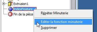
40 Defining elements you wish to hide All the events specified in the basic elements are displayed in the preview as standard. You can define elements you wish to hide using the tab "Hide" either by selecting specific elements or by selecting the configuration of an already existing Hide feature. Using the same principle as for configurations, you can also add, modify or delete configurations using the context menu contained in the Hide drop-down menu Saving configurations If you click on the button "Save configuration" you will replace the current configuration file with the contents of all the configurations defined in the function. You can modify the configuration file path via the options contained in inventoolswatch. When you save your data, the configuration currently active is saved in the same way as a standard configuration and will be loaded the next time the function is used Modifying the function You can modify all the function parameters starting from an existing event. You simply double-click on the event you wish to modify in the navigator or alternatively click and select "Modify hourtrack function" to display modify window. This window is the same as the create window and contains the elements currently in use. Clicking on "Cancel" will take you back to the element you first created, and "Ok" will re-create the entire function with the modifications included.
41 41

42 Numerals This function allows you to create numeral transfers for watch dials, using either a single part or an assembly. You can define all the parameters for this function in an XML configuration file accessible either locally or online. Several different configurations can be created directly using this function, which can then be easily modified or deleted. To perform this function, you carry out the following sequence of operations: 1. Define the parameters for the function configuration path in options 2. Open a file or an assembly containing at least one face 3. Start the function 4. Select the construction face 5. Select the central point (work-point, sketch-point, vertex, axis or edge of which the horizontal projection creates a point) 6. Define the function parameters according to the interactive preview 7. Validate by clicking on Ok Defining the basic elements You can select the configuration you require, you can create a new configuration, you can rename a configuration or delete an existing one by using the context menu in the drop-down menu. You can also define parameters for the following elements in this section: Minimum and maximum number Selection of the face and central point Diameter of the construction circle for the numerals Shift from base work plane
 Horizontal external (numerals outside the construction circle) Visant Semi-visant")
43 Extrusion parameters The numerals are represented by extrusions. In this section you can define the parameters you wish to use for extrusion Text formatting In this section you can define the text alignment you wish to use and you can format the numerals. The following types of alignment are available: Horizontal internal (numerals inside of the construction circle) Horizontal external (numerals outside the construction circle) Visant Semi-visant Visant turned (visant with 90 rotation in trigono metric direction) You can use the width parameter to increase or decrease the width of the text blocks used. The standard value is 1.


44 Defining elements you wish to hide All the events specified in the basic elements are displayed in the preview as standard. You can define elements you wish to hide using the tab "Hide" either by selecting specific elements or by selecting the configuration of an already existing Hide feature. Using the same principle as for configurations, you can also add, modify or delete configurations using the context menu contained in the Hide drop-down menu Saving configurations If you click on the button "Save configuration" you will replace the current configuration file with the contents of all the configurations defined in the function. You can modify the configuration file path via the options contained in inventoolswatch. When you save your data, the configuration currently active is saved in the same way as a standard configuration and will be loaded the next time the function is used Modifying the function You can modify all the function parameters starting from an existing event. You simply double-click on the event you wish to modify in the navigator or alternatively click and select "Modify numerals function" to display modify window. This window is the same as the create window and contains the elements currently in use. Clicking on "Cancel" will take you back to the element you first created, and "Ok" will re-create the entire function with the modifications included.

45 Tachymeter With this function you can create a tachymeter for watch dials, using either a single piece or an assembly. You can define all the parameters for this function in an XML configuration file accessible either locally or online. Several different configurations can be created directly using this function, which can then be easily modified or deleted. To perform this function, you carry out the following sequence of operations: 1. Define the parameters for the function configuration path in options 2. Open a file or an assembly containing at least one face 3. Start the function 4. Select the construction face 5. Select the central point (work-point, sketch-point, vertex, axis or edge of which the horizontal projection creates a point) 6. Define the function parameters according to the interactive preview 7. Validate by clicking on Ok Defining the basic elements You can select the configuration you require, you can create a new configuration, you can rename a configuration or delete an existing one by using the context menu in the drop-down menu. You can also define parameters for the following elements in this section: Select the face and central point


46 46 Diameter of the construction circle for the numerals Diameter of construction circle for the primary hour-markers Diameter of construction circle for the secondary hour-markers Shift from base work plane Choice of hour-marker In this section you can define the primary and secondary hour-markers that can be used as well as their presentation format. The following types of hour-marker are available: Rectangle Circle Flat-based triangle Inverted triangle Ellipse Rounded rectangle Small-base trapezium Large-base trapezium Double rectangle You can define the dimensions for all types of hourtracks. Hour-markers can be represented as flat surfaces or extrusions. You can define the parameters you use depending on the end-result you require. Where extrusion is concerned, you will find operation and direction parameters under the tab "Text" Text formatting In this section you can define the text alignment you wish to use and you can format the numerals. The following types of alignment are available: Visant Semi-visant Visant turned (visant with 90 rotation in trigono metric direction) If you click on the box containing the spectacles icon you can display a preview of the numerals that will be created. You can use the width parameter to increase or decrease the width of the text blocks used. The standard value is 1.

47 47 In this section you can also define the extrusion parameters (direction of the operation, distance and colour) to be used in creating the tachymeter numerals. The same operation and direction will also be used by the hour-markers if they have been defined as extruded elements Defining the elements to be displayed In this section you can modify the elements to be displayed in the preview. For each speed you can display the numeral, a primary hour-marker, a secondary hour-marker or a combination of the three. You can also define the elements to be displayed using the "Display" tab. You do this either by deselecting specific elements, or by selecting the configuration for an existing Hide feature. Using the same principle as for configurations, you can also add, modify or delete configurations using the context menu contained in the Hide drop-down menu. You can add or delete an already existing speed by clicking on the first column and then using the context menu.
How to...create a Video VBOX Gauge in Inkscape. So you want to create your own gauge? How about a transparent background for those text elements?
 BASIC GAUGE CREATION The Video VBox setup software is capable of using many different image formats for gauge backgrounds, static images, or logos, including Bitmaps, JPEGs, or PNG s. When the software
3 AXIS STANDARD CAD. BobCAD-CAM Version 28 Training Workbook 3 Axis Standard CAD
 3 AXIS STANDARD CAD This tutorial explains how to create the CAD model for the Mill 3 Axis Standard demonstration file. The design process includes using the Shape Library and other wireframe functions
Autodesk Fusion 360 Training: The Future of Making Things Attendee Guide
 Autodesk Fusion 360 Training: The Future of Making Things Attendee Guide Abstract After completing this workshop, you will have a basic understanding of editing 3D models using Autodesk Fusion 360 TM to
Introduction To Inkscape Creating Custom Graphics For Websites, Displays & Lessons
 Introduction To Inkscape Creating Custom Graphics For Websites, Displays & Lessons The Inkscape Program Inkscape is a free, but very powerful vector graphics program. Available for all computer formats
Tutorial 1 Engraved Brass Plate R
 Getting Started With Tutorial 1 Engraved Brass Plate R4-090123 Table of Contents What is V-Carving?... 2 What the software allows you to do... 3 What file formats can be used?... 3 Getting Help... 3 Overview
ME009 Engineering Graphics and Design CAD 1. 1 Create a new part. Click. New Bar. 2 Click the Tutorial tab. 3 Select the Part icon. 4 Click OK.
 PART A Reference: SolidWorks CAD Student Guide 2014 2 Lesson 2: Basic Functionality Active Learning Exercises Creating a Basic Part Use SolidWorks to create the box shown at the right. The step-by-step
Autodesk Inventor Design Exercise 2: F1 Team Challenge Car Developed by Tim Varner Synergis Technologies
 Autodesk Inventor Design Exercise 2: F1 Team Challenge Car Developed by Tim Varner Synergis Technologies Tim Varner - 2004 The Inventor User Interface Command Panel Lists the commands that are currently
40. Sim Module - Common Tools
 HSC Sim Common Tools 15021-ORC-J 1 (33) 40. Sim Module - Common Tools Table of Contents 40.1. Drawing flowsheets and adding tables to flowsheets... 2 40.1.1. Drawing units... 2 40.1.2. Drawing streams...
CPM-200 User Guide For Lighthouse for MAX
 CPM-200 User Guide For Lighthouse for MAX Contents Page Number Opening the software 2 Altering the page size & Orientation 3-4 Inserting Text 5 Editing Text 6 Inserting Graphics 7-8 Changing the Colour
CHAPTER 1 COPYRIGHTED MATERIAL. Finding Your Way in the Inventor Interface
 CHAPTER 1 Finding Your Way in the Inventor Interface COPYRIGHTED MATERIAL Understanding Inventor s interface behavior Opening existing files Creating new files Modifying the look and feel of Inventor Managing
Introduction to SolidWorks for Technology. No1: Childs Toy
 Introduction to SolidWorks for Technology No1: Childs Toy Table of Contents Table of Contents... 1 Introduction... 2 Part Modelling: Cab... 3 Part Modelling: Base... 6 Part Modelling: Wheel... 12 Assembly:
Autodesk Inventor - Basics Tutorial Exercise 1
 Autodesk Inventor - Basics Tutorial Exercise 1 Launch Inventor Professional 2015 1. Start a New part. Depending on how Inventor was installed, using this icon may get you an Inch or Metric file. To be
BD CellQuest Pro Analysis Tutorial
 BD CellQuest Pro Analysis Tutorial Introduction This tutorial guides you through a CellQuest Pro Analysis run like the one demonstrated in the CellQuest Pro Analysis Movie on the BD FACStation Software
3D Design with 123D Design
 3D Design with 123D Design Introduction: 3D Design involves thinking and creating in 3 dimensions. x, y and z axis Working with 123D Design 123D Design is a 3D design software package from Autodesk. A
Motic Images Plus 3.0 ML Software. Windows OS User Manual
 Motic Images Plus 3.0 ML Software Windows OS User Manual Motic Images Plus 3.0 ML Software Windows OS User Manual CONTENTS (Linked) Introduction 05 Menus and tools 05 File 06 New 06 Open 07 Save 07 Save
This section provides an overview of the features available within the Standard, Align, and Text Toolbars.
 Using Toolbars Overview This section provides an overview of the features available within the Standard, Align, and Text Toolbars. Using toolbar icons is a convenient way to add and adjust label objects.
Keynote 08 Basics Website:
 Website: http://etc.usf.edu/te/ Keynote is Apple's presentation application. Keynote is installed as part of the iwork suite, which also includes the word processing program Pages and the spreadsheet program
Module 4A: Creating the 3D Model of Right and Oblique Pyramids
 Inventor (5) Module 4A: 4A- 1 Module 4A: Creating the 3D Model of Right and Oblique Pyramids In Module 4A, we will learn how to create 3D solid models of right-axis and oblique-axis pyramid (regular or
DentMILL. Basic Quick Guide. Copyright 2011.Roland DG Corporation R
 DentMILL Basic Quick Guide R1-111221 Copyright 2011.Roland DG Corporation Table of Contents User Interface... 2 Workflow from the preparation to exporting data... 3 Basic operation procedures... 4 Step
Virtual MODELA USER'S MANUAL
 Virtual MODELA USER'S MANUAL Virtual MODELA is a program that simulates the movement of the tool on the screen. Contents Contents Part 1 Introduction 1-1 System Requirements... 4 1-2 Overview of Virtual
Solo 4.6 Release Notes
 June9, 2017 (Updated to include Solo 4.6.4 changes) Solo 4.6 Release Notes This release contains a number of new features, as well as enhancements to the user interface and overall performance. Together
BusinessObjects Frequently Asked Questions
 BusinessObjects Frequently Asked Questions Contents Is there a quick way of printing together several reports from the same document?... 2 Is there a way of controlling the text wrap of a cell?... 2 How
A Study of Angles & Curves
 A Study of Angles & Curves Method 1: Cutting Quilt Shapes/Using the Shapes Tools Open BERNINA CutWork Software. Make sure that Create New is selected. Click Next. Place a dot in front of New Graphic. Select
Design and Print Instruction Manual
 Diamond Design Design and Print Instruction Manual Contents Installation 1 Installing the Diamond Design Software 2-3 Installing the ORIGINAL Argox OS-214 printer drivers 4 Installing the EXCEL Argox OS-314
SEER-3D: An Introduction
 SEER-3D SEER-3D allows you to open and view part output from many widely-used Computer-Aided Design (CAD) applications, modify the associated data, and import it into SEER for Manufacturing for use in
BASICS OF MOTIONSTUDIO
 EXPERIMENT NO: 1 BASICS OF MOTIONSTUDIO User Interface MotionStudio combines draw, paint and animation in one easy easy-to-use program gram to save time and make work easy. Main Window Main Window is the
A Step-by-step guide to creating a Professional PowerPoint Presentation
 Quick introduction to Microsoft PowerPoint A Step-by-step guide to creating a Professional PowerPoint Presentation Created by Cruse Control creative services Tel +44 (0) 1923 842 295 training@crusecontrol.com
Insight: Measurement Tool. User Guide
 OMERO Beta v2.2: Measurement Tool User Guide - 1 - October 2007 Insight: Measurement Tool User Guide Open Microscopy Environment: http://www.openmicroscopy.org OMERO Beta v2.2: Measurement Tool User Guide
By PAD Product Development and Support Team
 Release Note Of PAD 2 V6 Pattern Design By PAD Product Development and Support Team 1 PAD System is a trademark and a system developed by: PAD System International Limited. Flat A, 2/F, Cheung Wing Industrial
Unit 21 - Creating a Navigation Bar in Macromedia Fireworks
 Unit 21 - Creating a Navigation Bar in Macromedia Fireworks Items needed to complete the Navigation Bar: Unit 21 - House Style Unit 21 - Graphics Sketch Diagrams Document ------------------------------------------------------------------------------------------------
NiceForm User Guide. English Edition. Rev Euro Plus d.o.o. & Niceware International LLC All rights reserved.
 www.nicelabel.com, info@nicelabel.com English Edition Rev-0910 2009 Euro Plus d.o.o. & Niceware International LLC All rights reserved. www.nicelabel.com Head Office Euro Plus d.o.o. Ulica Lojzeta Hrovata
Tutorial Tracing and Machining Images
 Getting Started With Tutorial Tracing and Machining Images VCarve Pro Disclaimer All CNC machines (routing, engraving, and milling) are potentially dangerous and because Vectric Ltd has no control over
Getting started with Solid Edge with Synchronous Technology
 Getting started with Solid Edge with Synchronous Technology Publication Number MU29000-ENG-1000 Proprietary and Restricted Rights Notice This software and related documentation are proprietary to Siemens
Impress Guide Chapter 11 Setting Up and Customizing Impress
 Impress Guide Chapter 11 Setting Up and Customizing Impress This PDF is designed to be read onscreen, two pages at a time. If you want to print a copy, your PDF viewer should have an option for printing
OpenForms360 Validation User Guide Notable Solutions Inc.
 OpenForms360 Validation User Guide 2011 Notable Solutions Inc. 1 T A B L E O F C O N T EN T S Introduction...5 What is OpenForms360 Validation?... 5 Using OpenForms360 Validation... 5 Features at a glance...
User Manual Mobile client User Interface Version 5.0. Powered by
 User Manual Mobile client User Interface Version 5.0 Powered by Cartographic browser Gomap 4 1 Access control 5 1.1 Public access 5 1.2 Secured access 5 1.3 Multiple applications 5 2 Organisation 6 3 Parameters
SolidWorks Intro Part 1b
 SolidWorks Intro Part 1b Dave Touretzky and Susan Finger 1. Create a new part We ll create a CAD model of the 2 ½ D key fob below to make on the laser cutter. Select File New Templates IPSpart If the SolidWorks
Chapter 4 Feature Design Tree
 4-1 Chapter 4 Feature Design Tree Understand Feature Interactions Use the FeatureManager Design Tree Modify and Update Feature Dimensions Perform History-Based Part Modifications Change the Names of Created
Laser Machine User Manual:
 Laser Machine User Manual: OPERATOR ( EasyCut / LaserCut version 5.3 ) v1.0 CTR Laser Machine Operator Manual ( EasyCut version 5.3 ) ~ version 1.0 1 CONTENTS Section 1: Tutorials...5 1.1. How to Cut with
Layout and display. STILOG IST, all rights reserved
 2 Table of Contents I. Main Window... 1 1. DEFINITION... 1 2. LIST OF WINDOW ELEMENTS... 1 Quick Access Bar... 1 Menu Bar... 1 Windows... 2 Status bar... 2 Pop-up menu... 4 II. Menu Bar... 5 1. DEFINITION...
Tutorial VCarving Christmas Decorations
 Getting Started With Tutorial VCarving Christmas Decorations VCarve Pro Disclaimer All CNC machines (routing, engraving, and milling) are potentially dangerous and because Vectric Ltd has no control over
With ClaroIdeas you can quickly and easily create idea maps using a combination of words, symbols and pictures.
 Welcome to ClaroIdeas ClaroIdeas is a fresh tool to support the creation and editing of concept maps or idea maps using visual and audio components. It has been specifically developed to support people
Copyright and License
 Manual ver. 2 1 Copyright and License Original version of dbook was developed by Zeta Inc., NPO URAP and Eigo UEHARA. Current version is developed by Zeta Inc., NPO URAP, Eigo UEHARA and Masami ISODA.
QUADRA-CHEK 2000 Demo User's Manual. Evaluation Unit
 QUADRA-CHEK 2000 Demo User's Manual Evaluation Unit English (en) 06/2018 Contents Contents 1 Fundamentals...7 2 Software Installation...11 3 Basic Operation... 17 4 Software Configuration...41 5 Quick
Profile Modeler Profile Modeler ( A SuperControl Product )
") Profile Modeler ( A SuperControl Product ) - 1 - Index Overview... 3 Terminology... 3 Launching the Application... 4 File Menu... 4 Loading a File:... 4 To Load Multiple Files:... 4 Clearing Loaded Files:...
Profile Modeler ( A SuperControl Product ) - 1 - Index Overview... 3 Terminology... 3 Launching the Application... 4 File Menu... 4 Loading a File:... 4 To Load Multiple Files:... 4 Clearing Loaded Files:...
Fig. A. Fig. B. Fig. 1. Fig. 2. Fig. 3 Fig. 4
 Create A Spinning Logo Tutorial. Bob Taylor 2009 To do this you will need two programs from Xara: Xara Xtreme (or Xtreme Pro) and Xara 3D They are available from: http://www.xara.com. Xtreme is available
BoA Tools Page 1 / 31
 BoA Tools Page 1 / 31 Standard tools Overview 2 Work pane 3 3D-2D file Main palette 6 Layout Main Palette 9 Navigation tools 11 Workplane Palette 14 Cursor Palette 21 Numeric control 24 Selection by Criteria
2D Design. Window. 3D Window. Toolpat h Operati ons. Navigation Homepage. Layer Managemen t. Component Manager. Modeling Tools
 Navigation Homepage Click on the region of the interface you are interested in to navigate to the relevant section of this manual. At the foot of each page is a Navigation Homepage link, click on this
Autodesk Inventor 6 Essentials Instructor Guide Chapter Four: Creating Placed Features Chapter Outline This chapter provides instruction on the follow
 Chapter Four: Creating Placed Features Chapter Outline This chapter provides instruction on the following topics and provides exercises for students to practice their skills. Day Two Topic: How to create
Press the Plus + key to zoom in. Press the Minus - key to zoom out. Scroll the mouse wheel away from you to zoom in; towards you to zoom out.
 Navigate Around the Map Interactive maps provide many choices for displaying information, searching for more details, and moving around the map. Most navigation uses the mouse, but at times you may also
Parametric Modeling. With. Autodesk Inventor. Randy H. Shih. Oregon Institute of Technology SDC PUBLICATIONS
 Parametric Modeling With Autodesk Inventor R10 Randy H. Shih Oregon Institute of Technology SDC PUBLICATIONS Schroff Development Corporation www.schroff.com www.schroff-europe.com 2-1 Chapter 2 Parametric
hdalbum User Designer Guide Collect Create Share Designer V 1.2
 hdalbum User Designer Guide 2017 Collect Create Share Designer V 1.2 Table of Contents Contents Welcome to the hdalbum Designer... 2 Features... 2 System Requirements... 3 Supported File Types... 3 Installing
Laser Engraving Using Base and Mass Production Modules
 ARPATHIA GRAPHIC INTERFACE Users Reference Guide Laser Engraving Using Base and Mass Production Modules 1 Table of Contents Page CGI Modules Carpathia Installation Carpathia Document Writer installation
CONTASign Pro User Manual
 CONTASign Pro User Manual CONTASign PRO MANUAL v3.5 rev01 Page 1 of 51 CONTA-CLIP Contents Page No. 1. Main Window Layout 4 - Window Layout Customisation 5 - Window Configuration 6 2. Start Menu & Quick
This document should only be used with the Apple Macintosh version of Splosh.
 Splosh 1 Introduction Splosh is an easy to use art package that runs under both Microsoft Windows and the Macintosh Mac OS Classic or Mac OS X operating systems. It should however be noted that the Apple
Getting Started with ShowcaseChapter1:
 Chapter 1 Getting Started with ShowcaseChapter1: In this chapter, you learn the purpose of Autodesk Showcase, about its interface, and how to import geometry and adjust imported geometry. Objectives After
Libraries. Multi-Touch. Aero Peek. Sema Foundation 10 Classes 2 nd Exam Review ICT Department 5/22/ Lesson - 15
 10 Classes 2 nd Exam Review Lesson - 15 Introduction Windows 7, previous version of the latest version (Windows 8.1) of Microsoft Windows, was produced for use on personal computers, including home and
Equipment Support Structures
 Equipment Support Structures Overview Conventions What's New? Getting Started Setting Up Your Session Creating a Simple Structural Frame Creating Non-uniform Columns Creating Plates with Openings Bracing
User s Guide. Valvova Oy
 User s Guide Valvova Oy June 21, 2017 CONTENTS Contents 1 Timeline 2 1.1 Program startup......................................... 3 1.2 Calendar............................................. 3 1.3 Go to
Board Viewer INSTRUCTION MANUAL
 Board Viewer INSTRUCTION MANUAL CheckSum, Inc. P.O. Box 3279 Arlington, WA 98223 (360) 435-5510 Fax (360) 435-5535 Web Site: www.checksum.com P/N 4400-048 Revision 3/2003 Copyright 1990-2003, CheckSum,
Exercise Guide. Published: August MecSoft Corpotation
 VisualCAD Exercise Guide Published: August 2018 MecSoft Corpotation Copyright 1998-2018 VisualCAD 2018 Exercise Guide by Mecsoft Corporation User Notes: Contents 2 Table of Contents About this Guide 4
USER GUIDE ikdesign V1.1. Advanced software for Inflatable kite design
 USER GUIDE ikdesign V1.1 Advanced software for Inflatable kite design http://perso.orange.fr/ikdesign/ User guide, ikdesign v1.1. September 4, 2007. Thanks to Laure Gicquel for the correction. ikdesign
SolidWorks 2½D Parts
 SolidWorks 2½D Parts IDeATe Laser Micro Part 1b Dave Touretzky and Susan Finger 1. Create a new part In this lab, you ll create a CAD model of the 2 ½ D key fob below to make on the laser cutter. Select
Module 2 Review. Assemblies and Rendering. Why Use Assemblies. Assemblies - Key Concepts. Sketch Planes Sketched Features.
 Module 2 Review Assemblies and Rendering EF 101 Modules 3.1, 3.2 Sketch Planes Sketched Features Extrude, Revolve Placed Features Hole, Fillet, Chamfer, Shell, Rect. Pattern Drawing Views Base, Ortho,
VANGUARD LOAD TAP CHANGER ANALYZER (LTCA) VERSION 2.xx SOFTWARE MANUAL. LTCA-10, LTCA-40, WRM-10P, WRM-40, TRM-20, TRM-40, TRM-203, and TRM-403
 VERSION 2.xx SOFTWARE MANUAL. LTCA-10, LTCA-40, WRM-10P, WRM-40, TRM-20, TRM-40, TRM-203, and TRM-403") VANGUARD LOAD TAP CHANGER ANALYZER (LTCA) VERSION 2.xx SOFTWARE MANUAL For Use with Vanguard s LTCA-10, LTCA-40, WRM-10P, WRM-40, TRM-20, TRM-40, TRM-203, and TRM-403 Load Tap Changer Analyzers and Winding
VANGUARD LOAD TAP CHANGER ANALYZER (LTCA) VERSION 2.xx SOFTWARE MANUAL For Use with Vanguard s LTCA-10, LTCA-40, WRM-10P, WRM-40, TRM-20, TRM-40, TRM-203, and TRM-403 Load Tap Changer Analyzers and Winding
Beginning Tutorial the Lego
 Beginning Tutorial the Lego In this tutorial, you will construct a simple hollowed-out block with a hole in it (looks like a Lego). You will learn the basics of creating and modifying sketches and features.
AVS4YOU Programs Help
 AVS4YOU Help - AVS Document Converter AVS4YOU Programs Help AVS Document Converter www.avs4you.com Online Media Technologies, Ltd., UK. 2004-2012 All rights reserved AVS4YOU Programs Help Page 2 of 39
ORGANIZING YOUR ARTWORK WITH LAYERS
 9 ORGANIZING YOUR ARTWORK WITH LAYERS Lesson overview In this lesson, you ll learn how to do the following: Work with the Layers panel. Create, rearrange, and lock layers and sublayers. Move objects between
Creating Interactive PDF Forms
 Creating Interactive PDF Forms Using Adobe Acrobat X Pro for the Mac University Information Technology Services Training, Outreach, Learning Technologies and Video Production Copyright 2012 KSU Department
TRAINING SESSION Q3 2016
 There are 6 main topics in this training session which is focusing on 3D Import and 2D Drawing Tips and Tricks in IRONCAD. Content 3D modeling kernels... 2 3D Import... 3 Direct Face Modeling... 5 Unfold
Getting_started_EN (Ind : 3) 06/01/2014. elecworks. Getting Started
 06/01/2014. elecworks. Getting Started") Getting_started_EN (Ind : 3) 06/01/2014 elecworks Getting Started 1 Start with elecworks This document has been made to help you in starting elecworks. It summarizes the features available. If you would
Getting_started_EN (Ind : 3) 06/01/2014 elecworks Getting Started 1 Start with elecworks This document has been made to help you in starting elecworks. It summarizes the features available. If you would
INKSCAPE BASICS. 125 S. Prospect Avenue, Elmhurst, IL (630) elmhurstpubliclibrary.org. Create, Make, and Build
 elmhurstpubliclibrary.org. Create, Make, and Build") INKSCAPE BASICS Inkscape is a free, open-source vector graphics editor. It can be used to create or edit vector graphics like illustrations, diagrams, line arts, charts, logos and more. Inkscape uses Scalable
INKSCAPE BASICS Inkscape is a free, open-source vector graphics editor. It can be used to create or edit vector graphics like illustrations, diagrams, line arts, charts, logos and more. Inkscape uses Scalable
Part 1: Basics. Page Sorter:
 Part 1: Basics Page Sorter: The Page Sorter displays all the pages in an open file as thumbnails and automatically updates as you add content. The page sorter can do the following. Display Pages Create
Memo Block. This lesson includes the commands Sketch, Extruded Boss/Base, Extruded Cut, Shell, Polygon and Fillet.
 Commands Used New Part This lesson includes the commands Sketch, Extruded Boss/Base, Extruded Cut, Shell, Polygon and Fillet. Click File, New on the standard toolbar. Select Part from the New SolidWorks
Autodesk Inventor 2016
 Parametric Modeling with Autodesk Inventor 2016 Randy H. Shih SDC PUBLICATIONS Better Textbooks. Lower Prices. www.sdcpublications.com Powered by TCPDF (www.tcpdf.org) Visit the following websites to learn
Scheme Editor. Version 6.3. Manual Edition 1
 Scheme Editor Version 6.3 Manual Edition 1 Bosch Rexroth AG Print Title Type of Documentation Document Typecode Internal File Reference Scheme Editor Version 6.3 Manual Print RS-0361ea845ef863400a6846a0010a9c70-19-en-US-3
Keynote Basics Website:
 Keynote Basics Website: http://etc.usf.edu/te/ Keynote is Apple's presentation application. Keynote is installed as part of the iwork suite, which also includes the word processing program Pages. If you
Introduction. Table Basics. Access 2010 Working with Tables. Video: Working with Tables in Access To Open an Existing Table: Page 1
 Access 2010 Working with Tables Introduction Page 1 While there are four types of database objects in Access 2010, tables are arguably the most important. Even when you're using forms, queries, and reports,
A Guide to Processing Photos into 3D Models Using Agisoft PhotoScan
 A Guide to Processing Photos into 3D Models Using Agisoft PhotoScan Samantha T. Porter University of Minnesota, Twin Cities Fall 2015 Index 1) Automatically masking a black background / Importing Images.
Plotting. Documentation. DDBSP - Dortmund Data Bank Software Package
 Plotting Documentation DDBSP - Dortmund Data Bank Software Package DDBST Software & Separation Technology GmbH Marie-Curie-Straße 10 D-26129 Oldenburg Tel.: +49 441 361819 0 Fax: +49 441 361819 10 E-Mail:
Microsoft Visio Working with Shapes
 Working with Visio Shapes Shape is the general term for the objects you will find on a stencil and objects created using the drawing tools. These include geometric shapes such as rectangles, triangles
3D Modeling and Design Glossary - Beginner
 3D Modeling and Design Glossary - Beginner Align: to place or arrange (things) in a straight line. To use the Align tool, select at least two objects by Shift left-clicking on them or by dragging a box
Vision MET/METCAD. 2D measurement system
 Vision MET/METCAD 2D measurement system September 2012 ~ Contents ~ 1 GENERAL INFORMATION:... 3 1.1 PRECISION AND RESOLUTION... 3 2 GETTING STARTED:... 5 2.1 USER IDENTIFICATION... 5 2.2 MAIN WINDOW OF
Dolphin PartMaster Wire EDM
 Dolphin PartMaster Wire EDM Copyright 2000-2017 Dolphin CADCAM Systems Ltd. This document is copyrighted and all rights are reserved. This document may not, in whole or in part, be copied or reproduced
Table of Contents. Revu ipad. v3.6. Navigation. Document Manager. File Access. Markups. Signature Tool. Field Verification Measurements
 Table of Contents Navigation Document Manager File Access Markups Signature Tool Field Verification Measurements Editing Properties Tool Sets & the Tool Chest Markups List Forms Studio Sessions Studio
Funasset Limited Foundry House Foundry Road Taunton Somerset TA1 1JJ. Tel: +44 (0) Fax: +44 (0) mailmarkup.com funasset.
 Fax: +44 (0) mailmarkup.com funasset.") Funasset Limited Foundry House Foundry Road Taunton Somerset TA1 1JJ Tel: +44 (0)1823 365864 Fax: +44 (0)1823 277266 mailmarkup.com funasset.com Copyright 2012 Funasset Limited. All rights reserved. Products
Funasset Limited Foundry House Foundry Road Taunton Somerset TA1 1JJ Tel: +44 (0)1823 365864 Fax: +44 (0)1823 277266 mailmarkup.com funasset.com Copyright 2012 Funasset Limited. All rights reserved. Products
Tutorial 1 Bulls Head Sign
 Getting Started With Tutorial 1 Bulls Head Sign VCarve Pro Disclaimer All CNC machines (routing, engraving, and milling) are potentially dangerous and because Vectric Ltd has no control over how the software
Chapter 2 Using Slide Masters, Styles, and Templates
 Impress Guide Chapter 2 Using Slide Masters, Styles, and Templates OpenOffice.org Copyright This document is Copyright 2007 by its contributors as listed in the section titled Authors. You can distribute
End User Guide. 2.1 Getting Started Toolbar Right-click Contextual Menu Navigation Panels... 2
 TABLE OF CONTENTS 1 OVERVIEW...1 2 WEB VIEWER DEMO ON DESKTOP...1 2.1 Getting Started... 1 2.1.1 Toolbar... 1 2.1.2 Right-click Contextual Menu... 2 2.1.3 Navigation Panels... 2 2.1.4 Floating Toolbar...
Using SymPrint to Make Overlays, Templates & More...
 Welcome to SymPrint SymPrint is an easy-to-use tool for creating communication overlays, worksheets, classroom activities and more using a modern toolbar and common-sense interface modeled after the programs
Module 4B: Creating Sheet Metal Parts Enclosing The 3D Space of Right and Oblique Pyramids With The Work Surface of Derived Parts
 Inventor (5) Module 4B: 4B- 1 Module 4B: Creating Sheet Metal Parts Enclosing The 3D Space of Right and Oblique Pyramids With The Work Surface of Derived Parts In Module 4B, we will learn how to create
UNIT 11: Revolved and Extruded Shapes
 UNIT 11: Revolved and Extruded Shapes In addition to basic geometric shapes and importing of three-dimensional STL files, SOLIDCast allows you to create three-dimensional shapes that are formed by revolving
Bombardier Business Aircraft Customer Services. Technical Publications. SmartPubs Viewer 3.0 User Guide. Updated January 2013 [2013]
![Bombardier Business Aircraft Customer Services. Technical Publications. SmartPubs Viewer 3.0 User Guide. Updated January 2013 [2013]](/thumbs/90/103657167.jpg "Bombardier Business Aircraft Customer Services. Technical Publications. SmartPubs Viewer 3.0 User Guide. Updated January 2013 [2013]") Bombardier Business Aircraft Customer Services Technical Publications SmartPubs Viewer 3.0 User Guide Updated January 2013 [2013] Table of Contents Application Views... 5 Collection View... 5 Manual View...
Bombardier Business Aircraft Customer Services Technical Publications SmartPubs Viewer 3.0 User Guide Updated January 2013 [2013] Table of Contents Application Views... 5 Collection View... 5 Manual View...
Microsoft Office Word. Help. Opening a Document. Converting from Older Versions
 Microsoft Office 2007 - Word Help Click on the Microsoft Office Word Help button in the top right corner. Type the desired word in the search box and then press the Enter key. Choose the desired topic
LinkMotion and CorelDraw 9, 10, 11, 12, X3, X4, X5, X6, X7 and X8:
 LinkMotion and CorelDraw 9, 10, 11, 12, X3, X4, X5, X6, X7 and X8: After you install LinkMotion software and set up all settings launch CorelDraw software. Important notes: Solustan s LinkMotion driver
Introduction to SolidWorks Basics Materials Tech. Wood
 Introduction to SolidWorks Basics Materials Tech. Wood Table of Contents Table of Contents... 1 Book End... 2 Introduction... 2 Learning Intentions... 2 Modelling the Base... 3 Modelling the Front... 10
Tutorial Base Module
 Tutorial Base Module CONTENTS Part 1 - Introduction to the CycloLog desktop... 7 1.1 Introduction to the CycloLog desktop... 7 1.2 Using Log Data panes... 9 Part 2 - Importing and displaying well log data...
Autodesk Fusion 360: Model. Overview. Modeling techniques in Fusion 360
 Overview Modeling techniques in Fusion 360 Modeling in Fusion 360 is quite a different experience from how you would model in conventional history-based CAD software. Some users have expressed that it
A "Quick and Dirty" Introduction to THE GEOMETER'S SKETCHPAD
 A "Quick and Dirty" Introduction to the GEOMETER'S SKETCHPAD v. 4.0 Dynamic Geometry in the Mathematics Classroom _/_/_/ _/_/_/ _/_/ _/_/ Dr. _/ _/ _/ _/ Distinguished Teaching Professor _/_/_/ _/_/ _/
Chapter 7 Inserting Spreadsheets, Charts, and Other Objects
 Impress Guide Chapter 7 Inserting Spreadsheets, Charts, and Other Objects OpenOffice.org Copyright This document is Copyright 2007 by its contributors as listed in the section titled Authors. You can distribute