MCETool V2 User Manual
|
|
|
- Doreen Cole
- 5 years ago
- Views:
Transcription

1 AN Quality requirement category: Industry Features Programming of RAM, Flash and OTP memory for IRMCKxxx and IRMCFxxx devices Debugging via standard JTAG interface Tuning of motor parameters via virtual UART All interfaces are galvanically isolated 3.3 VDC output voltage to target Internal generation of OTP programming voltage USB interface to PC for power and data Ships with all required cables Supported Devices imotion IRMCK099 imotion IRMCx100 series imotion IRMCx300 series imotion 2.0 Devices (virtual UART only) Description MCETOOLV2 (formerly IR Cable V2 ) is designed to program and debug IRMCK099/ IRMCx100/ IRMCx300 series imotion motor control ICs on the user s target board (final application board) or on IRMCx evaluation boards. The MCETOOLV2 can also be used for motor and inverter board parameter tuning via the UART to USB interface. Infineon provides the respective PC tools (MCEProgrammer & MCEDesigner) for download on the web page. Tools are delivered as a part of Installer package (e.g. 99 Series Installer and 100 Series Installer ) User Manual Please read the Important Notice and Warnings at the end of this document <Revision 1.4>
2 Table of contents Table of contents 1 Introduction Software installation for MCETOOLV MCE Programmer, MCE Designer and CP210x driver installation Software installation step by step Getting Started Using MCETOOLV2 with MCE Programmer PC port configuration Target device programming Using MCETOOLV2 with MCE Designer PC port configuration Programming target device...11 User Manual 2 <Revision 1.4>
 or on corresponding Evaluation Kits, to enable engineers to design the application code during development.")
3 Introduction 1 Introduction MCETOOLV2 (in some older documents named IR Cable V2 ) is designed to program IRMCK099/ IRMCx100/ IRMCx300 series digital motor control ICs on the user s target board (final application board) or on corresponding Evaluation Kits, to enable engineers to design the application code during development. MCETOOLV2 contains the following basic configuration and functions: Power: 5V DC power supply (Powered through USB Mini B type interface) PC interface: USB to virtual communication port with baud rate of up to 256Kbps Isolated 3.3V DC Output for target Isolated output interface: o 8 Pin JTAG o 4 Pin UART Figure 1 Picture of MCETOOLV2 Function description 1. Isolated UART port 2. Isolated JTAG port 3. Green LED1: Indicates when Vpp is enabled during programming the target 4. Yellow LED: When blinking indicates that MCETOOLV2 is powered and MCU is working. 5. Switch SW1: Provides 3.3V to target board, and provides program voltage Vpp when programming OTP. 6. PC USB cable port for UART operation 7. PC USB cable port for JTAG operation 8. Red LED6: Indicates presence of 5V USB power supply. When MCETOOLV2 connects to PC, this LED shows that the MCETOOLV2 has been powered from 5V USB power. User Manual 3 <Revision 1.4>
 is as shown in figure below Figure 2 UART Connector pinout To use as an isolated USB to JTAG converter, PC USB cable plugs in to USB-JTAG, and the JTAG output port")

4 Introduction To use as an isolated USB to UART converter, PC USB cable plugs in to USB-UART, and the UART output port is used. The pinout for UART connector (J2) is as shown in figure below Figure 2 UART Connector pinout To use as an isolated USB to JTAG converter, PC USB cable plugs in to USB-JTAG, and the JTAG output port is used. The pinout for JTAG connector (J3) is as shown in figure below Figure 3 JTAG Connector pinout Switch SW1 is used to power target from isolated DC-DC converted on MCETOOLV2. If switch is in upward position, target is powered from MCETOOLV2 and if it s in downward position, target is powered from external source. The MCETOOLV2 is supported by following software tools: MCE Programmer (v and above) MCE Designer (v and above) User Manual 4 <Revision 1.4>
5 Software installation for MCETOOLV2 2 Software installation for MCETOOLV2 MCETOOLV2 is supported by MCE Programmer as well as by MCE Designer and needs CP210x virtual com port drivers to communicate with PC. The installation procedure for MCE Programmer, MCE Designer and CP210x virtual com port drivers is as follows. 2.1 MCE Programmer, MCE Designer and CP210x driver installation MCE Programmer, MCE Designer and CP210x drivers are available for download from the Infineon website and are also part of the software package Infineon-99series-kit-mce-installer-SW-v02_02-EN.exe (or higher version) in 99 Series Installer or Infineon-100serieskitmceinstaller-SW-v03_05-EN.exe (or higher version) in 100 Series Installer which contains the following support items for MCETOOLV2: Pre-Requisite software MCE Programmer software MCE Designer software CP2102 driver. Note: The following description is based on the use of the all-in-one installation package Infineon- 99series-kit-mce-installer-SW-v02_02-EN. The installation procedure might differ slightly if individual installation files are used for the software tools above. User Manual 5 <Revision 1.4>


6 Software installation for MCETOOLV2 2.2 Software installation step by step Step 1: Double click the Infineon-99series-kit-mce-installer-SW-v02_02-EN.exe file. Installation process will check if the PC already has the software: Microsoft Visual C ++ Runtime 11.0 and Microsoft.NET Framework 3.5 or above version. If there is no such software, the installation will install them, otherwise it will go to the next step. Figure 4 Pre-Requisites software installation Step 2: After the pre-requisite software installs, it will install MCE Designer, MCE Programmer and other packaged application software. Figure 5 MCE Designer, MCE Programmer and other software installation Press Next to select the install path, the default path isc:\program Files\iMotion. This will overwrite previously installed files. The user can select a different path to preserve an earlier version of Infineon-99serieskit-mce-installer-SW-v02_02-EN. Then press Next and start the Infineon-99series-kit-mce-installer-SW-v02_02- EN software installation. User Manual 6 <Revision 1.4>


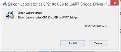


7 Software installation for MCETOOLV2 Step 3: The driver installation dialog will launch during Infineon-99series-kit-mce-installer-SW-v02_02-EN installation. If the PC has installed the CP210x chip driver before, press Cancel to cancel the operation, otherwise follow the prompt to finish unpacking and installing the driver. Figure 6 C210x chip driver installations Step 4: After CP210x chip driver installation the following dialog IRMCK099 Series imotion Design Kit Support successfully installed will appear. Check/Uncheck boxes to visit imotion support site and view release notes and press Finish to exit the installation wizard. Figure 7 Installation completed dialog User Manual 7 <Revision 1.4>
8 Getting Started 3 Getting Started 3.1 Using MCETOOLV2 with MCE Programmer PC port configuration When MCETOOLV2 is used for the first time or the COM port number has changed, configure the connection port and the baud rate. If there is no connection or the configuration has problem, MCE Programmer will prompt warning information. Launch MCE Programmer and select Tools >IR Cable V2 Serial Port Setup. Choose the right serial port and set the baud rate to bps (IRCable V2 default). Figure 8 Configuring the connection port Note: If there is no MCETOOLV2 connection to the PC or the configuration is mismatched, the following error messages will appear. Please reconfigure the port settings. Figure 9 Open COM port failed / Port configured incorrectly User Manual 8 <Revision 1.4>
9 Getting Started Target device programming Select desired operation for MCETOOLV2 from drop-down list, select.bin file and click Download or Program + Verify button (depending upon desired operation) Figure 10 Select desired programming option And wait for desired operation to finish. Figure 11 Programming complete Switch SW1 is used to power target from isolated DC-DC converted on MCETOOLV2. If switch is in upward position, target is powered from MCETOOLV2 and if it s in downward position, target is powered from external source. When Programmming OTP, switch in upward position is required. User Manual 9 <Revision 1.4>
10 Getting Started 3.2 Using MCETOOLV2 with MCE Designer PC port configuration Launch MCE Designer, open desired configuration file (with extension.irc) Figure 12 Configuration file selection Highlight or click child window with title System XXX.irc and select Preferences > Connection. Select proper com port from drop down list and press OK button. Figure 13 Com port selection User Manual 10 <Revision 1.4>
11 Getting Started Programming target device Highlight or click child window with title System XXX.irc and select Tools > Load Target. Select desired firmware file (with.bin extension) using Browse.. button, press Open button in file selection dialog and then OK button in Load Target dialog. Figure 14 Firmware file selection Wait for programming to finish. Figure 15 Programming in progress User Manual 11 <Revision 1.4>

12 Getting Started Figure 16 Programming complete When configuration file is loaded or MCETOOLV2 is used for the first time or the COM port number has changed, configure the connection port. If there is no connection or the configuration has problem, MCE Designer will prompt warning information. In this case, highlight or click child window with title System XXX.irc and select Preferences > Connection. Select proper com port from drop down list and press OK. User Manual 12 <Revision 1.4>
13 Revision history Revision history Major changes since the last revision Version number Revision date Revision description First Release Box figure updated 2. Document title updated 3. Software download link updated 4. Interface illustration updated User Manual 13 <Revision 1.4>
14 Trademarks of Infineon Technologies AG µhvic, µipm, µpfc, AU-ConvertIR, AURIX, C166, CanPAK, CIPOS, CIPURSE, CoolDP, CoolGaN, COOLiR, CoolMOS, CoolSET, CoolSiC, DAVE, DI-POL, DirectFET, DrBlade, EasyPIM, EconoBRIDGE, EconoDUAL, EconoPACK, EconoPIM, EiceDRIVER, eupec, FCOS, GaNpowIR, HEXFET, HITFET, HybridPACK, imotion, IRAM, ISOFACE, IsoPACK, LEDrivIR, LITIX, MIPAQ, ModSTACK, my-d, NovalithIC, OPTIGA, OptiMOS, ORIGA, PowIRaudio, PowIRStage, PrimePACK, PrimeSTACK, PROFET, PRO-SIL, RASIC, REAL3, SmartLEWIS, SOLID FLASH, SPOC, StrongIRFET, SupIRBuck, TEMPFET, TRENCHSTOP, TriCore, UHVIC, XHP, XMC Trademarks updated November 2015 Other Trademarks All referenced product or service names and trademarks are the property of their respective owners. Edition Published by Infineon Technologies AG München, Germany 2017 Infineon Technologies AG. All Rights Reserved. Do you have a question about this document? erratum@infineon.com Document reference IMPORTANT NOTICE The information given in this document shall in no event be regarded as a guarantee of conditions or characteristics ( Beschaffenheitsgarantie ). With respect to any examples, hints or any typical values stated herein and/or any information regarding the application of the product, Infineon Technologies hereby disclaims any and all warranties and liabilities of any kind, including without limitation warranties of non-infringement of intellectual property rights of any third party. In addition, any information given in this document is subject to customer s compliance with its obligations stated in this document and any applicable legal requirements, norms and standards concerning customer s products and any use of the product of Infineon Technologies in customer s applications. The data contained in this document is exclusively intended for technically trained staff. It is the responsibility of customer s technical departments to evaluate the suitability of the product for the intended application and the completeness of the product information given in this document with respect to such application. For further information on the product, technology, delivery terms and conditions and prices please contact your nearest Infineon Technologies office ( WARNINGS Due to technical requirements products may contain dangerous substances. For information on the types in question please contact your nearest Infineon Technologies office. Except as otherwise explicitly approved by Infineon Technologies in a written document signed by authorized representatives of Infineon Technologies, Infineon Technologies products may not be used in any applications where a failure of the product or any consequences of the use thereof can reasonably be expected to result in personal injury.
.dp Interface Gen2 Firmware Update for XDPL8220
 White Paper Revision 1.0 About this document Scope and Purpose The increased functionality of the XDPL8220 Digital PFC+Flyback Controller IC requires firmware version 2.4.3 or newer in the.dp Interface
OPTIGA TM Trust B SLE95250
 OPTIGA TM Trust B SLE95250 Evaluation Kit User Guide About this document Scope and purpose This is the User Guide for OPTIGA TM Trust B evaluation kit. It gives the detailed guideline of how to use OPTIGA
Getting Started with the XDPL8220 Reference Board Using.dp Vision Software
 AN_GS_201611_PL21_003 Getting Started with the XDPL8220 Reference Board Using.dp Vision Software XDP T M digital power About this document Scope and purpose The purpose of this document is to give a quick
TLE9845 Application Kit PN User s Manual
 Product Family: TLE984xQX Figure 1 TLE9845QX Application Kit with PN-Halfbridge About this document Scope and purpose The TLE9845_APPKIT_PN is designed to evaluate hardware and software functionalities
TLE986xQX Family TLE987xQX Family. Overview. Delta Sheet. This document lists all differences between BE-Step and BF-Step.
 Delta Sheet TLE986xQX Family Overview This document lists all differences between -Step and BF-Step. This document applies to the following products: TLE9861QXA20 TLE9867QXA20 TLE9867QXA40 TLE9869QXA20
XMC1000 EEPROM emulation and data retention
 AP32384 EEPROM emulation and data retention About this document Scope and purpose This document provides a brief introduction to the use of the Microcontroller family with emulated EEPROM. Intended audience
.dp Interface Gen2. About this document. Table of Contents. Scope and purpose
 About this document Scope and purpose This document provides insights of the.dp Interface Gen2 (.dpifgen2) and information on the electrical functionality and the functionality provided by the firmware
Scope and purpose The scope of this document is to describe the architecture and usage of OPTIGA Trust X1 PC Library implementation
 SLS 32AIA020X2/4 OPTIGA Trust X1 About this document Scope and purpose The scope of this document is to describe the architecture and usage of OPTIGA Trust X1 PC Library implementation Intended audience
.dp Interface Gen2. About this document. Table of Contents. Scope and purpose
 About this document Scope and purpose This document provides insights of the.dp Interface Gen2 (.dpifgen2) and information on the electrical functionality and the functionality provided by the firmware
imotion Link User Manual
 AN2018-12 imotion Link User Manual_V1.0_EN imotion Link User Manual Quality requirement category: Industry Features Programming of firmware and parameters file for IMC101T \IMC102T\IMC30xA devices Tuning
TLE8110ED Switching Inductive Loads and External Clamping
 TLE8110ED Switching Inductive Loads and External Clamping Product Family: Flex Multichannel Low-Side Switches About this document Scope and purpose This application note is intended to provide additional
TLE (-3)QX(V33) MR-SBC Family. Reference: Data Sheet. Overview. Errata Sheet. TLE9263-3QX-Data-Sheet-110-Infineon, Rev 1.1
QX(V33) MR-SBC Family. Reference: Data Sheet. Overview. Errata Sheet. TLE9263-3QX-Data-Sheet-110-Infineon, Rev 1.1") Reference: Data Sheet TLE9263-3QX-Data-Sheet-110-Infineon, Rev 1.1 Overview Errata Sheet This document lists the errata of the related to the Data Sheet, TLE9263-3QX-Data-Sheet-110- Infineon, Rev 1.1.
Reference: Data Sheet TLE9263-3QX-Data-Sheet-110-Infineon, Rev 1.1 Overview Errata Sheet This document lists the errata of the related to the Data Sheet, TLE9263-3QX-Data-Sheet-110- Infineon, Rev 1.1.
TLE984x Evalboard Rev 1.3 User Manual
 User Manual Figure 1 About this document Scope and purpose The TLE984x Evalboard is designed to evaluate hardware and software functionalities of the TLE984x device family. All Pins of the chip are able
TLE985x Evaluation Board User Manual
 Figure 1 About this document Scope and purpose The is designed to evaluate hardware and software functionalities of the TLE985x device family. All pins of the chip are able to be contacted via pin headers.
Design-in Application Note for OPTIGA Trust E
 Version 1.0 Design-in Application Note for OPTIGA Trust E Implementation guideline for System-Integr ation About this document Scope and purpose This document explains the benefit of Certificates, the
OPTIGA Trust X1 SLS 32AIA020X2/4. XMC Application Notes. About this document
 SLS 32AIA020X2/4 OPTIGA Trust X1 About this document Scope and purpose The scope of this document is to describe the architecture and usage of OPTIGA Trust X1 Library implementation on XMC4500 Relax Kit
Silicon Germanium Low Noise Amplifier BGA7L1BN6
 AN469 Silicon Germanium Low Noise Amplifier BGA7L1BN6 Low Noise Amplifier for LTE Band 17 Application Using 21 Components for Matching About this document Scope and purpose This application note describes
Multi-channel Switching ICs for Engine Management Applications
 Multi-channel Switching ICs for Engine Management Applications TLE9104SH, TLE8110ED & TLE8718SA Evaluation Boards and GUI User Manual About this document This document details the functionality and the
KeyPerformanceandPackageParameters Type VCE IC VCEsat,Tvj=25 C Tvjmax Marking Package AIGW50N65H5 650V 50A 1.66V 175 C AG50EH5 PG-TO247-3
 HighspeedfastIGBTinTRENCHSTOP TM 5technology FeaturesandBenefits: HighspeedH5technologyoffering: BestinClassefficiencyinhardswitchingandresonant topologies PlugandplayreplacementofpreviousgenerationIGBTs
32-bit Microcontroller Series for Industrial Applications UG_201511_PL30_002. Board User Manual
 XMC1000 32-bit Microcontroller Series for Industrial Applications XMC1300 Digital Power Control Card User Manual Board User Manual Scope and purpose This document describes the features and hardware details
HybridKit Drive Advanced Features
 AN-HPDKIT-ADVANCED-FEATURES HybridKit Drive Advanced Features About this document This application note describes advanced programmable features of the evaluation kits HybridKit Drive and HybridKit Drive
Infineon microphone in noise-cancelling headsets
 AN538 Infineon microphone in noise-cancelling headsets About this document Scope and purpose This application note is intended to illimunate the reader on the challenges of designing a noise-cancellation
Manual for HybridKIT Evaluation Gate Board
 AN-HPDKIT-GATEDRIVE Manual for HybridKIT Evaluation Gate Board About this document This application note describes the features as well as limitations of the evaluation gate driver board EVAL-6ED100HPDRIVE-AS
XMC1000. Device Guide. Microcontrollers. Interrupt Subsystem V Microcontroller Series for Industrial Applications.
 XMC1000 Microcontroller Series for Industrial Applications Interrupt Subsystem Device Guide V1.0 2013-04 Microcontrollers Edition 2013-04 Published by Infineon Technologies AG 81726 Munich, Germany 2013
EVAL-M1-099M-C User Manual
 AN2017-18 EVAL-M1-099M-C User Manual EVAL-M1-099M-C User Manual About this document Scope and purpose This application note provides an overview of the evaluation board EVAL-M1-099M including its main
Bulb Driving Capability of HITFET+
 Z8F57645289 Bulb Driving Capability of HITFET+ About this document Scope and purpose One of the target applications of HITFET+ device family is bulb driving, particularly for interior lightning bulbs.
HybridKit Drive Quickstart Manual
 AN-HPDKIT-QUICKSTART HybridKit Drive Quickstart Manual About this document This application note gives a quick start guide for both evaluation kits HybridKit Drive and HybridKit Drive Sense. These evaluation
XMC1000, XMC4000 Microcontroller Series for Industrial Applications
 XMC1000, XMC4000 Microcontroller Series for Industrial Applications Migration from Timer2 to CCU4/CCU8 Migration Guide V1.0 2013-06 Microcontrollers Edition 2013-06 Published by Infineon Technologies AG
Dual H-Bridge shield. Dual H-Bridge shield - board user manual. Shield for DC motor control with IFX9202. About this document.
 - board user manual Dual H-Bridge shield About this document Scope and purpose This document details the functionality and the required steps for running the Dual H-Bridge shield. Included are instructions
AURIX TC27x variants. Data Sheet Addendum. 32-bit microcontroller. v1.3, M i c r o c o n t r o l l e r s
 T C277 / TC275 / T270 AURIX 32-bit microcontroller Addendum v1.3, 2015-10-01 M i c r o c o n t r o l l e r s Table of Contents About this document... 3 1. Variants BC Step... 4 2. Variants CA Step... 5
TPMS SP37T. ROM Library Function Guide. Sense & Control. Tire Pressure Monitoring Sensor
 TPMS SP37T High integrated single-chip TPMS sensor with a low power embedded microcontroller and wireless FSK/ASK UHF transmitter SP37T 1300kPa Version A4 ROM Library Function Guide Revision 1.0, 2012-04-03
ORIGA 2L High Temperature
 SLE95201H ORIGA 2L High Temperature Features Asymmetric authentication based on Elliptic Curve Cryptographic (ECC) ORIGA TM Digital Certificate (ODC) with device personalization Large NVM for storage of
ASCLIN Asynchronous Synchronous Interface
 Asynchronous Synchronous Interface AURIX Microcontroller Training V1.0 2019-03 Please read the Important Notice and Warnings at the end of this document Port Control Asynchronous Synchronous Interface
High Side Switch Shield
 User Manual High Side Switch Shield About this document Scope and purpose This document describes how to use the High Side Switch Shield. Intended audience Engineers, hobbyists and students who want to
SPOC +2 User Manual Multichannel SPI High-Side Power Controller
 SPOC +2 User Manual About this document Scope and purpose This User Manual is intended to enable users to integrate the SPOC TM +2 Software for the SPOC TM +2- Demoboard. Intended audience This document
For XMC1000 Family CPU-12A-V1. XMC1200 CPU Card. Board User's Manual. Revision 2.0, Microcontroller
 For XMC1000 Family CPU-12A-V1 Board User's Manual Revision 2.0, 2013-12-18 Microcontroller Edition 2013-12-18 Published by Infineon Technologies AG 81726 Munich, Germany 2013 Infineon Technologies AG All
Power Management & Multimarket
 TVS Diode Transient Voltage Suppressor Diodes ESD201-B2-03LRH Bi-directional Dual Diode for ESD/Transient Protection ESD201-B2-03LRH Data Sheet Revision 1.1, 2012-09-26 Final Power Management & Multimarket
EVAL-M1-183M User Manual
 AN207-3 About this document Scope and purpose This application note provides an overview of the evaluation board EVAL-M-83M including its main features, key data, pin assignments, mechanical dimensions
Trusted Platform Module
 TPM SLB 9670 TCG Rev. 116 SLB 9670VQ1.2 SLB 9670XQ1.2 Data Sheet Revision 1.0, 2015-11-05 Chip Card and Security Revision History Page or Item Subjects (major changes since previous revision) Revision
Power Management & Multimarket
 Hipac High performance passive and actives on chip BGF106C SIM Card Interface Filter and ESD Protection BGF106C Datasheet Rev. 3.1, 2013-01-16 Final Power Management & Multimarket Revision History Rev.
3D Magnetic Sensor 2 Go - TLE493D-A2B6
 TLE493D-A2B6 3D-MS2GO User Manual About this document Scope and purpose This document provides an introduction to the 3D Magnetic Sensor 2 Go kit and should enable the reader to efficiently carry out own
ASC Bootstrap Loader for XMC1000
 AP32277 ASC Bootstrap Loader for About this document Scope and purpose This Application Note describes how to use the ASC BSL to download the program into flash for microcontroller family. The example
For XMC4000 Family. Automation I/O Card. Revision 1.0,
 Hexagon Application Kit For XMC4000 Family AUT_ISO-V1 Board User's Manual Revision 1.0, 2012-02-28 Microcontroller Edition 2012-02-28 Published by Infineon Technologies AG 81726 Munich, Germany 2012 Infineon
XMC4000 Microcontroller Series for Industrial Applications
 XMC4000 Microcontroller Series for Industrial Applications PCB Design Guidelines Application Guide V1.0 2013-11 Microcontrollers Edition 2013-11 Published by Infineon Technologies AG 81726 Munich, Germany
TLx5012B 2go Evaluation Kit
 About this document Scope and purpose This document describes the evaluation kit for the TLx5012B GMR based angle sensor. The purpose of this document is to describe the software installation process and
Power Management & Multimarket
 Protection Device TVS (Transient Voltage Suppressor) ESD218-B1 Series Bi-directional, 24 V, 3 pf, 21, 42, RoHS and Halogen Free compliant ESD218-B1-2ELS ESD218-B1-2EL Data Sheet Revision 1.1, 215-1-13
Power Management & Multimarket
 Protection Device TVS (Transient Voltage Suppressor) ESD114-U1-02 Series Uni-directional, 5.3 V, 0.4 pf, 0402, 0201, RoHS and Halogen Free compliant ESD114-U1-02ELS ESD114-U1-02EL Data Sheet Revision 1.0,
Power Management & Multimarket
 Protection Device TVS (Transient Voltage Suppressor) Bi-directional, 5.5 V,.3 pf, 21, RoHS and Halogen Free compliant Quality Requirement Category: Standard Data Sheet Revision 1., 216-5-1 Final Power
Power Management & Multimarket
 TVS Diode Transient Voltage Suppressor Diodes ESD206-B1-02 Series Ultra Low Clamping Bi-directional ESD / Transient / Surge Protection Diode ESD206-B1-02ELS ESD206-B1-02EL Data Sheet Revision 1.5, 2013-12-19
Scope: SW Installation: Start the Package PROG-KIT. Current. Page 1
 Sensor 2 Go Quick Instruction Guide Scope: The following instruction gives a quick overview about the Sensor r 2 Go GUI. The GUI can also be used for the PGSISI-2 based TLI4970050 PROG-KIT. SW Installation:
Application Note TLE9252V. About this document. Application Note. Safety Recommendations Z8F
 Application Note TLE9252V Safety Recommendations About this document Scope and purpose This document provides application information for the transceiver TLE9252V from Infineon Technologies AG as Physical
XE166 Family AP Application Note. Microcontrollers. X E D r i v e C a r d H a r d w a r e D e s c r i p t i o n Board REV.
 XE166 Family AP16160 X E 1 6 4 D r i v e C a r d H a r d w a r e D e s c r i p t i o n Application Note V1.0, 2009-03 Microcontrollers Edition 2009-03 Published by Infineon Technologies AG 81726 Munich,
Power Management & Multimarket
 Protection Devices TVS (Transient Voltage Suppressor) ESD102-U1-02ELS Uni-directional, 3.3 V, 0.4 pf, 0201, RoHS ESD102-U1-02ELS Data Sheet Revision 1.2, 2015-12-14 Final Power Management & Multimarket
Power Management & Multimarket
 TVS Diode Transient Voltage Suppressor Diodes ESD207-B1-02 Series Ultra Low Clamping Bi-directional ESD / Transient / Surge Protection Diodes ESD207-B1-02ELS ESD207-B1-02EL Data Sheet Revision 1.3, 2013-12-19
Power Management & Multimarket
 TVS Diodes Transient Voltage Suppressor Diodes ESD3V3U4ULC Ultra-low Capacitance ESD / Transient Protection Array ESD3V3U4ULC Data Sheet Rev. 1.2, 2012-07-03 Final Power Management & Multimarket Edition
PMA71xx/PMA51xx. IFX Software and Tools Support. Software and Tools Overview. Wireless Control. SmartLEWIS TM MCU. Revision 1.
 SmartLEWIS TM MCU IFX Software and Tools Support Software and Tools Overview Revision 1.0, 2009-11-19 Wireless Control Edition 2009-11-19 Published by Infineon Technologies AG 81726 Munich, Germany 2009
XMC LED current control explorer kit
 XMC LED current control explorer kit Quick start guide The XMC LED current control explorer kit is an evaluation kit that introduces the user to continuous conduction mode buck LED driving solution with
TVS Diodes. ESD3V3U1U Series. Data Sheet. Industrial and Multi-Market. Transient Voltage Suppressor Diodes
 TVS Diodes Transient Voltage Suppressor Diodes ESD3V3U1U Series Uni-directional Ultra-low Capacitance ESD / Transient Protection Diode ESD3V3U1U-02LS ESD3V3U1U-02LRH Data Sheet Revision 1.0, 2011-04-12
TVS Diodes. ESD5V3U1U Series. Data Sheet. Industrial and Multi-Market. Transient Voltage Suppressor Diodes
 TVS Diodes Transient Voltage Suppressor Diodes ESD5V3U1U Series Uni-directional Ultra-Low Capacitance ESD / Transient Protection Diode ESD5V3U1U-02LS ESD5V3U1U-02LRH Data Sheet Revision 1.0, 2011-05-27
XC2000 Family AP Application Note. Microcontrollers. XC2236N Drive Card Description V1.0,
 XC2000 Family AP16179 Application Note V1.0, 2010-07 Microcontrollers Edition 2010-07 Published by Infineon Technologies AG 81726 Munich, Germany 2010 Infineon Technologies AG All Rights Reserved. LEGAL
Power Management & Multimarket
 TVS Diodes Transient Voltage Suppressor Diodes ESD5V5U5ULC Ultra-low Capacitance ESD / Transient / Surge Protection Array ESD5V5U5ULC Data Sheet Revision 1.4, 2016-06-27 Final Power Management & Multimarket
TVS Diodes. ESD8V0R1B Series. Data Sheet. Industrial and Multi-Market. Transient Voltage Suppressor Diodes. Bi-directional Low Capacitance TVS Diode
 TVS Diodes Transient Voltage Suppressor Diodes ESD8V0R1B Series Bi-directional Low Capacitance TVS Diode ESD8V0R1B-02EL ESD8V0R1B-02ELS Data Sheet Revision 2.0, 2010-12-15 Final Industrial and Multi-Market
Power Management & Multimarket
 TVS Diodes Transient Voltage Suppressor Diodes ESD5V5U5ULC Ultra-low Capacitance ESD / Transient / Surge Protection Array ESD5V5U5ULC Data Sheet Revision 1.3, 2015-07-16 Final Power Management & Multimarket
Application Note No. 097
 Application Note, Rev. 1.0, Mai. 2006 Application Note No. 097 Using BCR402R/BCR402U at High Supply Voltages RF & Protection Devices Edition 2006-05-08 Published by Infineon Technologies AG 81726 München,
Industrial PROFET. Universal Application Board User s Manual
 Industrial PROFET Universal Application Board User s Manual Introduction Industrial PROFET Universal Application Board The Industrial PROFET demo board can be used to easily evaluate a wide range of single
Power Management & Multimarket
 TVS Diode Transient Voltage Suppressor Diodes ESD24VL1B Series Low Capacitance Bi-directional ESD / Transient Protection Diode ESD24VL1B-02LS ESD24VL1B-02LRH Data Sheet Revision 1.1, 2012-05-04 Final Power
TVS Diode. ESD3V3S1B Series. Data Sheet. Industrial and Multi-Market. Transient Voltage Suppressor Diodes
 TVS Diode Transient Voltage Suppressor Diodes ESD3V3S1B Series Ultra Low Clamping Bi-directional ESD / Transient Protection Diode ESD3V3S1B-02LRH ESD3V3S1B-02LS Data Sheet Revision 1.1, 2011-11-28 Final
NovalithIC H-Bridge Demo Board
 Demo Board Description V1.0, 2011-09-23 Automotive Power General Description Figure 1 Demo board (top view) 1 General Description The NovalithIC H-Bridge/Dual-Halfbridge Demo Board contains two NovalithICs
TVS Diode. ESD5V3L1B Series. Data Sheet. Industrial and Multi-Market. Transient Voltage Suppressor Diodes
 TVS Diode Transient Voltage Suppressor Diodes ESD5V3L1B Series Bi-directional Low Capacitance ESD / Transient Protection Diode ESD5V3L1B-02LRH ESD5V3L1B-02LS Data Sheet Revision 1, 2011-08-04 Final Industrial
XE166 Family AP Application Note. Microcontrollers. UConnect XE162N Hardware Description V1.0,
 XE166 Family AP90005 Application Note V1.0, 2010-01 Microcontrollers Edition 2010-01 Published by Infineon Technologies AG 81726 Munich, Germany 2010 Infineon Technologies AG All Rights Reserved. LEGAL
Analog Absolute Pressure Sensor KP226E0109. TurboMAP. Data Sheet. Revision 1.0, Sense & Control
 KP226E0109 TurboMAP Data Sheet Revision 1.0, 2018-04-26 Sense & Control Table of Contents 1 Product Description............................................................... 5 1.1 Features.........................................................................
Programmer Kit. User s Manual. Sense and Control. Current Sensor - TLI Software Description for Evaluation Kits Rev. 1.
 Programmer Kit Current Sensor - TLI 4970 User s Manual Rev. 1.2, 2013-06-06 Sense and Control Edition 2013-06-06 Published by Infineon Technologies AG 81726 Munich, Germany 2013 Infineon Technologies AG
Sensor supply in bus mode
 Sensor supply in bus mode Product Family: TLE5011, TLE5012, TLE5012B, TLE5012BD, TLI5012B About this document Scope and purpose Some applications require the use of several devices connected to the same
TVS Diodes ESD3V3U4ULC. Data Sheet. Industrial and Multi-Market. Transient Voltage Suppressor Diodes. Ultra Low Capacitance ESD Array ESD3V3U4ULC
 TVS Diodes Transient Voltage Suppressor Diodes ESD3V3U4ULC Ultra Low Capacitance ESD Array ESD3V3U4ULC Data Sheet Revision 0.9, 2010-10-14 Preliminary Industrial and Multi-Market Edition 2010-10-14 Published
Operating temperature T a
 Ω Operating temperature T a -24 Green Product (RoHS Compliant) General Description N channel vertical power FET with charge pump, ground referenced CMOS compatible input, monolithically integrated in Smart
TLT807B0EPV Demoboard
 Preface Scope and purpose This application note provides information about the usage of the TLT807B0 Demoboard. The TLT807B0 Demoboard is used to demonstrate the ultra low quiescent current linear voltage
TriCore AURIX Family. 32-bit AP32263 V
 TriCore AURIX Family 32-bit Using the RTC (Real-Time Clock) on the TC2x5 Application Kit Application Note V1.0 2014-04 Microcontrollers Edition 2014-04 Published by Infineon Technologies AG, 81726 Munich,
Smart High-Side Power Switch BSP742RI PG-DSO8. AEC qualified Green product (RoHS compliant)
") AEC qualified Green product (RoHS compliant) Ω PG-DSO8 General Description N channel vertical power FET with charge pump, ground referenced CMOS compatible input and diagnostic feedback, monolithically
AEC qualified Green product (RoHS compliant) Ω PG-DSO8 General Description N channel vertical power FET with charge pump, ground referenced CMOS compatible input and diagnostic feedback, monolithically
Application Note, V1.0, Jul AP08049 XC886/888CLM. Migration of Flash to ROM Device: Memory Protection Configurations.
 Application Note, V1.0, Jul. 2006 AP08049 XC886/888CLM Migration of Flash to ROM Device: Memory Protection Configurations Microcontrollers Edition 2006-07 Published by Infineon Technologies AG 81726 München,
XE164 UConnect Manual, V.1.1, February XE164 UConnect. Board REV. 2007/40. Microcontrollers. Never stop thinking.
 Manual, V.1.1, February 2008 XE164 Board REV. 2007/40 Microcontrollers Never stop thinking. Edition 2007-06 Published by Infineon Technologies AG 81726 München, Germany Infineon Technologies AG 2008. All
About this document. Application Note AN404
 Low N oise SiGe : BGA7L1N6 Single Band LTE L NA Using BGA7L1N6 Supporting Band -26 (859 - ) Application Note AN44 About this document Scope and purpose This application note describes Infineon s Low Noise
LOW EMI PWM INTELLIGENT POWER HIGH SIDE SWITCH
 Automotive grade Automotive IPS High side AUIPS72211R LOW EMI PWM INTELLIGENT POWER HIGH SIDE SWITCH Features Integrated bootstrap for 100kHz switching Optimized EMI switching Charge pump for DC operation
About this document. Application Note AN432
 Silicon Germanium Low Noise Amplifier : BGA7H1N6 Low N oise Amplifier for LTE Band -42 (3400 ), Using 0201 Compone n t s Application Note AN432 About this document Scope and purpose This application note
BGS12AL7-6. Data Sheet. Industrial & Multimarket. SPDT RF Switch. Revision 2.0,
 Data Sheet Revision 2.0, 2009-11-24 Industrial & Multimarket Edition 2009-11-24 Published by Infineon Technologies AG 81726 Munich, Germany 2009 Infineon Technologies AG All Rights Reserved. Legal Disclaimer
Easy Kit Board Manual
 User s Manual, V1.0, June2008 Easy Kit Board Manual Easy Kit - XC88x Microcontrollers Edition 2008-06 Published by Infineon Technologies AG, 81726 München, Germany Infineon Technologies AG 2008. All Rights
Intended audience This document is for anyone interested in exploring the motor control capabilities of the XMC1302 device.
 AN0- Eval-M-0 About this document Scope and purpose The purpose of this document is to provide a comprehensive description of functionalities and guide for the usage of the Eval-M-0 board which acts as
About this document. Application Note AN411
 Low N oise SiGe : BGA7M1N6 Single Band LTE L NA Using BGA7M1N6 Supporting Band -7 (262-269 MHz) Application Note AN411 About this document Scope and purpose This application note describes Infineon s Low
Application Note, V 1.1, Apr AP08006 C868. Interfacing SPI/I2C Serial EEPROM with C868 Microcontroller. Microcontrollers. Never stop thinking.
 Application Note, V 1.1, Apr. 2005 AP08006 C868 Interfacing SPI/I2C Serial EEPROM with C868 Microcontroller Microcontrollers Never stop thinking. Edition 2005-04-01 Published by Infineon Technologies AG
TPM. Data Sheet. Chip Card & Security ICs. Trusted Platform Module SLB9645 TCG Rev. 116 SLB9645VQ1.2 SLB9645TT1.2 SLB9645XT1.2 SLB9645XQ1.
 TPM SLB9645 TCG Rev. 116 SLB9645VQ1.2 SLB9645TT1.2 SLB9645XT1.2 SLB9645XQ1.2 Data Sheet Rev. 1.1, 2014-02-12 Chip Card & Security ICs Edition 2014-02-12 Published by Infineon Technologies AG 81726 Munich,
SmartLEWIS TM RX+ TDA5240/35/25 Explorer
 SmartLEWIS TM RX+ TDA5240/35/25 Explorer Configuration and Evaluation Software B12.6.33-51 High Sensitivity Receiver with Digital Baseband Processing (TDA5240/35) / Digital Slicer (5225) Addendum to Data
The evaluation board Eval-M1-CM610N3 was developed to support customers during their first steps designing applications with CIPOS Mini IPM.
 AN2017-09 EVAL-M1-CM610N3 Eval-M1-CM610N3 About this document Scope and purpose This application note provides an overview of the evaluation board Eval-M1-CM610N3 including its main features, key data,
Application Note, V 1.1, Feb AP DAP Connector. Microcontrollers
 Application Note, V 1.1, Feb. 2009 AP24003 Microcontrollers Edition 2009-02 Published by Infineon Technologies AG 81726 München, Germany Infineon Technologies AG 2009. All Rights Reserved. LEGAL DISCLAIMER
S e c u r i t y T a r g e t L i t e M B 1 1. R e c e r t i f i c a t i o n
 S e c u r i t y T a r g e t L i t e M 7 8 9 2 B 1 1 R e c e r t i f i c a t i o n C o m m o n C r i t e r i a C C v 3. 1 E A L 6 a u g m e n t e d ( E A L 6 + ) Resistance to attackers with HIGH attack
TLE986x/TLE987x Family BF-Step
 Application Note Rev. 1.00, 2016-12-05 Automotive Power Table of Contents Table of Contents 1 Abstract........................................................................ 4 2 Introduction.....................................................................
SmartLEWIS TM TRX - TDA5340. Software Example for TDA5340. Application Note. Wireless Sense & Control. Multi-channel RF transceiver for sub 1GHz
 SmartLEWIS TM TRX - TDA5340 for TDA5340 Multi-channel RF transceiver for sub 1GHz Application Note Revision 1.0, 2012-05-30 Wireless Sense & Control Edition 2012-05-30 Published by Infineon Technologies
XMC 2Go Kit with XMC1100
 Evaluation Board For XMC1000 Family Kit Version 1.0 Board User s Manual Revision 1.0, 2014-02-20 Microcontroller Edition 2014-02-20 Published by Infineon Technologies AG 81726 Munich, Germany 2014 Infineon
Application Note - PCB Layout & PIN Behavior Assessment
 Application Note - PB Layout & PIN Behavior Assessment Scope and purpose This document provides application information for the transceiver TLE9252V from Infineon Technologies AG as Physical Medium Attachment
Smart High-Side Power Switch for Industrial Applications One channel: 1 x 1 Ω
 Smart High-Side Power Switch for Industrial Applications One channel: 1 x 1 Ω ITS 4140N Features Current controlled input Product Summary Overvoltage protection V bbin(az) 62 V Operating voltage V Short
Infineon Technologies AG
 PUBLIC Infineon Technologies AG Chip Card and Security Evaluation Documentation including optional Software Libraries RSA - EC Toolbox FTL Common Criteria CCv3.1 EAL5 augmented (EAL5+) Resistance to attackers
ZCRMZNICE01ZEMG Crimzon In-Circuit Emulator
 Quick Start Guide QS006602-0408 Introduction Zilog s ZCRMZNICE01ZEMG Crimzon (ICE), shown in Figure 1, provides Crimzon chip family emulation with a Trace and Event system for program debugging using Zilog