Dymola Dynamic Modeling Laboratory. Dymola Release notes
|
|
|
- Patience Morrison
- 5 years ago
- Views:
Transcription
1 Dymola Dynamic Modeling Laboratory Dymola Release notes Dymola 2014
2 The information in this document is subject to change without notice. Document version: 1 Copyright by Dassault Systèmes AB. All rights reserved. Dymola is a registered trademark of Dassault Systèmes AB. Modelica is a registered trademark of the Modelica Association. Other product or brand names are trademarks or registered trademarks of their respective holders. Dassault Systèmes AB Ideon Science Park SE Lund Sweden Dymola.Support@3ds.com URL: Phone: Fax:
3 Contents 1 Important notes on Dymola About this booklet Dymola Introduction Additions and improvements in Dymola New and updated libraries Limited Availability Features Developing a model Smart Connect State machine support Hiding graphical connections (LA) Modelica Text editor improvements Improved resources handling when copying/renaming a class Opening of files by dragging them into Dymola main window supported Find in diagram layer supported Minor improvements Simulating a model CVODE solver generally supported Plot window Scripting Minor improvements Installation Software requirements Improvement of C Compiler test Minor improvements Other Simulation Environments Dymola Matlab interface Real-time simulation FMI Support in Dymola Code and Model Export Advanced Modelica Support Synchronous Modelica State Machines Minor improvements
4 4 3.7 New libraries Modelica_Synchronous library Updated libraries AirConditioning Library Engine Dynamics Library Hydraulics Library Hydro Power Library Liquid Cooling Library Optimization Library Pneumatics Library Thermal Power Library Vehicle Dynamics Library Documentation... 49
5 1 Important notes on Dymola Installation on Windows To translate models you must also install a supported Microsoft Visual Studio C++ compiler. The compiler is not distributed with Dymola. Note that free Microsoft compiler versions earlier than Microsoft Visual Studio Express 2008 are not supported (concerning full versions, some earlier versions are supported). Refer to section Software requirements on page 39 for more information. Administrator privileges are required for installation. 2 About this booklet This booklet covers Dymola The disposition is similar to the one in Dymola User Manual Volume 1 and 2; the same main headings are being used (except for, e.g., Libraries and Documentation). Dymola 2014 Release notes 5
6 3 Dymola Introduction Additions and improvements in Dymola A number of improvements and additions have been implemented in Dymola In particular, Dymola 2014 provides Synchronous Modelica support, according to the Modelica Language version 3.3 (previously Limited Availability). State machine support, according to the Modelica Language version 3.3 (previously Limited Availability). SUNDIALS CVODE solver generally supported. Extended FMI support. o Support of FMI 2.0 beta 4. o Improved source code export in FMUs. o GUI for FMI settings. Modelica Text editor improvements. o Lookup supported in automatic code completion. o Regular expressions supported for Find dialog. Plot features o Fast Fourier Transform (FFT) available as signal operator. o Duplicate diagrams. o Configurable time unit on x-axis o Create tables from trajectories. o Show plot and its corresponding command in command window. Diagram layer improvements o Smart Connect; objects are intuitively connected by, e.g., placing connectors on top of each other. o Visibility handling of graphical connections (Limited Availability) o Find in diagram layer supported. o Rotate while dragging component. o Component changed to icon when outside valid area. Message window improvements o Arbitrary part of message can be copied. o Soft wrapping supported. Improved resources handling when copying/renaming a class. 6
7 C Compiler test improved. Opening files in Dymola by drag-and-drop into main window supported New and updated libraries New libraries The following libraries are new: Modelica_Synchronous (previously Limited Availability), version 0.91 For more information about the new libraries, please see section New libraries starting on page 47. Updated libraries The following libraries have been updated: AirConditioning Library, version Engine Dynamics Library, version 1.1 Hydraulics Library, version Hydro Power Library, version 2.2 Liquid Cooling Library, version 1.1 Optimization Library, version 2.2 Pneumatics Library, version 1.6 Thermal Power Library, version 1.6 Vehicle Dynamics Library, version For more information about the updated libraries, please see the section Updated libraries starting on page Limited Availability Features This version of Dymola contains certain features which are labeled Limited Availability (LA). It means that the implementation might be partial, diagnostics partial, the testing is not complete, and no support/maintenance and only limited documentation is available. However, we provide them to you as early as possible in order for you learn about these features, plan for later use, and be able to give us your feedback. You typically need to set some switch to enable them. These features are planned to become Generally Available (GA) in the Dymola 2014 FD01 release. Please provide any feedback to The LA features are briefly described below and are marked (LA). Dymola 2014 Release notes 7
8 3.2 Developing a model Smart Connect In Dymola 2014, Smart Connect is introduced to simplify connecting objects. The features are enabled by default, but can be disabled generally by setting the flag Advanced.SmartConnect=false. These features are also disabled when Connect Mode is not selected. Working with the features, Ctrl+Z, or Escape, are the general commands used to undo an action. Note that if a connection dialog is needed to connect, it is displayed automatically. Only one connection that requires the connection dialog is supported per operation. Smart connection By placing a connector on top of a matching connector of another component, a connection is automatically created between the two connectors. In the example below, a capacitor is dragged to fit the connector of a resistor. A short highlight is seen when the connection is created and connected; the result is seen when dragging the capacitor away. The color of the highlight indicates degree of success: Green: Connection succeeded. 8
9 Yellow: It is possible to create a connection, but not with smart connect. This is the case with, e.g., expandable connectors and array of connectors. Red: Connection not possible; e.g. connectors are not matching. Drop component on connection A component can be dropped on a connection for automatic connection. Splitting a connection when dropping a matching component is also supported, e.g., dropping a heating resistor on the connection of two resistors: will result in: Two highlights are seen when dropping the component, one for the connection to the right of the component, and one for the connections to the left of the component. The layout of the original connection is kept. Dropping on a vertical connection is also supported. The connection is split only if the relevant sub connectors of the dropped component match the connection (in the above example the positive and negative pin). Dymola 2014 Release notes 9

10 Start connection from connection / Connect to connection A connection can now be started from an existing connection, and a connection can be ended on an existing matching connection. To start a new connection from an existing connection, right-click the existing connection and select Start Connection from the context menu: The connect command is started and the connection can be created the normal way. To end a connection on an existing matching connection, just click on the wanted location on the existing connection when connecting. (The cursor will be displayed as a hand on the existing connection if connection is possible.) The resulting connection is quickly highlighted: 10


11 3.2.2 State machine support General State machines according to Modelica Language version 3.3 are supported. In order to write state machines using Modelica 3.3, please note the following properties: For variables that are common between different states, the inner/outer concept has to be used, or alternatively graphical connections. State machines are clocked. For more information, including examples what can be done when it comes to e.g. hierarchical state machines, conditional data flow and applications like cruise control, please see the relevant papers available by the command Help > Documentation, and the tutorial available by the command File > Demos > Modelica Synchronous Tutorial. Creating and simulating a simple state machine The below is a short description of the basic state machine editor features in Dymola; for more information see above. To create states and transitions in Dymola 2014 the corresponding commands have been added to the Drawing toolbar: The Create Local State command can also be given as Edit > Create Local State. The command will display a menu: The state name and state class name can be entered. Show text can be selected if the equations in the state should be visible in the step, without having to enter the Modelica Text layer of that step. Pressing OK will create the state, but with dashed outline, since it must have a transition to be defined as a state: Dymola 2014 Release notes 11

12 It can be dragged and resized like any other object. The step can now be opened by doubleclicking it in the package browser, and code can be inserted using the Modelica Text editor. The name of the state can be changed afterwards by double-clicking the state. To change the Show text setting afterwards to display equations, the corresponding annotation in the code annotation(diagram(graphics={text(textstring="%statename")})) can be changed to annotation(diagram(graphics={text(textstring="%statetext")})) When the state is created, the Transition Mode is activated automatically; enabling creation of transitions by dragging, like dragging connections. You start dragging from the border of the state. The initial state of a state machine is defined by creating a specific transition; dragging a transition from the step above, and right-click after having dragged just as small distance (without connecting to anything) will give: Selecting Create Initial State will give: This state is now initial state, and since it has a transition it is presented as a valid state. Drawing another state and dragging a transition connection between them, the following menu will be displayed: 12
.")
13 The Condition is the condition that should be valid for the transition; it must be a Boolean expression. Immediate should be selected if the transition should fire when condition=true (this is called immediate transition ). If deselected, the transition will fire when previous(condition)=true (this is called delayed transition ). Reset should be selected if the target state (and states included in the target states, if any) should be reinitialized; i.e. included state machines are restarted in initial state and state variables are reset to their start values. Synchronize should be selected if all state machines within the source state must have reached their final state before the transition condition is tested for. Priority can be set to an integer corresponding to the priority; 1 is the highest priority. The font size can be set. Selecting i > 10 as condition, and deactivate Immediate will give when selecting OK: The transition is created as an arrow between the two states. It indicates the above selections The arrow direction is from the source state to the destination state. Dymola 2014 Release notes 13
14 The perpendicular bar of the transition is close to the destination state for an immediate transition, and close to the source state for a delayed transition. The arrow is filled for a reset transition, otherwise non-filled. A synchronize transition has an inverted fork at the source state. Priority is shown preceding the condition if not equal to 1 (e.g. 2: i>1). The transition can be created like any line, with corners that can be dragged; corners can be added and removed etc. Double-clicking the transition will display the menu above. Hierarchical state machines can easily be created by creating state machines in states. Having hierarchical state machines, the annotation annotation(showdiagram=true) that is set by default in new states is of importance. The default value is to display state machines inside a step. It is possible to select if enclosed steps should be displayed or not by right-clicking a step and ticking/unticking Show Diagram for each individual step: 14

15 Important: To enable the above selection, the mentioned annotation must be deleted in all states where this selection should be possible. (It is not sufficient to set the annotation to false, it overrides the menu anyway; the annotation must be deleted.) When simulating this model, a message will be displayed that since a clock is not defined; a default base clock with the period 1 second will be used; the period can be set using the variable browser: Hiding graphical connections (LA) In Dymola 2014 the user can easily use the context menu to hide graphical connections, improving the display of the diagram layer. To use this feature, the user must set the flag Advanced.InvisibleConnections=true. The flag is by default false; the selection below is by default not shown in the context menu. Dymola 2014 Release notes 15
16 Unticking Visible will give the following: Selecting one stub will also select the other: 16
. Dymola 2014 Release notes 17")
17 Hidden graphical connections can easily be displayed by setting Show hidden graphical objects reached by the command Edit > Options, in the Appearance tab. By default such objects are hidden. Accidental hiding is corrected using Edit > Undo (Ctrl+Z). Dymola 2014 Release notes 17

18 3.2.4 Modelica Text editor improvements Lookup supported in code completion The code completion now supports lookup in Modelica classes. When compiling e.g. Modelica.Math, the menu will only show functions within that library. Regular expressions supported in Find dialog The search engine used in the command Edit > Find, Edit > Replace, and the corresponding context menu entry Find and Replace is now enhanced to allow regular expressions. To use regular expressions, the checkbox Use regular expressions in the dialog box should be ticked. Special symbols in the regular expressions are: * Match everything.? Match any single character. {ab} Match characters a or b. {a-z} Match characters a through z. {^ab} Match any characters except a and b. E+ Match one or more occurrence of E. (ab cd) Match ab or cd. \d Match any digit. \w Match any digit or letter. ^ Match from start. $ Match at end. 18
 are not copied. 3.2.6 Opening of files by dragging them into Dymola main window supported Dymola files (.mo and.")
19 3.2.5 Improved resources handling when copying/renaming a class When using the commands Rename or New > Duplicate Class, directories pointed to by LibraryDirectory and IncludeDirectory are copied, and the references are updated. Note that presently other resources (e.g. images) are not copied Opening of files by dragging them into Dymola main window supported Dymola files (.mo and.moe files) that are dragged into the Dymola main window are automatically opened like performing the command File > Load on the files. (For information about this new load command, please see Load command introduced on page 20.) Find in diagram layer supported In Dymola 2014 the command Edit > Find can be used to search the diagram layer for components. In the example below, Rev is searched in the Robot model: Some features of this command: The search is recursive and automatic, i.e. you can start typing Rev and the list is automatically built, including components inside components etc. Dymola 2014 Release notes 19

20 The search first looks at local components, before looking at sub-components. The search is based on what is shown in the diagram layer when starting the search. Clicking on a result will select it, the diagram layer will be zoomed to display the result. This navigation does not influence the search, you can still select another component, or the In component button, or you can modify the search Minor improvements Load command introduced To be able to load a model without changing the current working directory, the command Load has been introduced. (Note the present possibility to set wanted working directory when opening Dymola using a shortcut with the preferred working directory as Start in.) Improvement of Split Model It is now possible to merge external connections if a submodel is created. This increases the simplification of a diagram. Having as a starting point selected the following: 20


21 Right-clicking and selecting Split Model from context menu, the following menu will appear: Keeping the default setting of Merge external connections will give the result: Dymola 2014 Release notes 21

22 Unticking the setting will give: Rotation while dragging supported Components can be rotated when dragging by using the arrow keys Left/Right or Ctrl+R. They can be zoomed using the arrow keys Up/Down. Improved display of components dragged into the diagram layer In Dymola 2014, a component dragged from the package browser to the diagram layer is immediately displayed, with exactly the location and size it will have, immediately when entering the diagram layer. Component changed to icon when outside valid area A component dragged from the component browser outside a valid area is indicated by an icon and a non-valid sign. 22

23 Copying of arbitrary text possible in Message window Any text part can now be selected (however not icons) and copied to the clipboard from the Messages window. Soft wrapping of text in Message window supported Soft wrapping of text in the Messages window is now supported. Improvement in propagation of parameters Propagation of parameters bound to other (local) parameters is now handled using hierarchical names of the resulting parameters. Note that this will cause issues if the local parameters are protected. In that case the default value has to be manually converted to a new scope. Controlling icons by parameters If a parameter expression is used as the second argument of DynamicSelect, and the expression can be evaluated, it is used also in Edit mode. First argument of DynamicSelect is used in case of failure. References to submodel parameters are also allowed. The feature can be disabled by setting Advanced.ActivateParameterValuesInDiagram=false. Displaying library-specific menus and toolbars in Dymola Library developers can now in their libraries include menus and toolbars that will be displayed in Dymola when opening the libraries. To do this, the annotation annotation( Dymola_containsMenu=true); must be present in the top level of the library (e.g. in package.mo). This causes all classes in the library to be searched for menu and toolbar annotations. Dymola 2014 Release notes 23
24 The package containing the menu and toolbar annotations must be located inside the library. An example of a menu created this way is the menu that will be displayed when opening the Optimization library version 2.2: The menu will disappear when performing File > Clear All or unloading the library. 3.3 Simulating a model CVODE solver generally supported In Dymola 2014, the SUNDIALS CVODE solver with Backward Differentiation Formula (BDF) and Newton iteration is generally supported (it was previously available only when generating FMUs); it now included in the list of algorithms that can be selected by using the command Simulation > Setup, the General tab. 24

25 For further details about the solver, please visit Dymola 2014 Release notes 25
 has been added to the list of signal operators, available using the context menu of a curve in the plot window.")
26 3.3.2 Plot window Signal operators: additions and improvements Fast Fourier Transform (FFT) available as signal operator In Dymola 2014 the Fast Fourier Transform (FFT) has been added to the list of signal operators, available using the context menu of a curve in the plot window. The resulting menu is: 26


27 The type of window can be selected: The default selection Rectangular gives equal weight to all points. Selecting More >>, the menu is extended: The Interval length gives together with the Horizontal range the Number of points. A new diagram is created when calling this operator: Dymola 2014 Release notes 27
28 The operator is also supported by scripting, the call for the above calculation is (freqpart, powers) = SignalOperators.Fourier.calculateFFT("CoupledClutches.mat", {"J1.w"}, 0, 1.2, 501, 1e+100, SignalOperators.Windows.Windowing.Rectangular); and the corresponding plot command that follow is plotarrays(freqpart, powers, legend={"j1.w"}, id=1); Note that the variables freqpart and powers are declared and available in the workspace after having executed the script for FFT. Calculation of a number of signal operators improved The following signal operators have been improved: Rectified Mean. RMS. AC Coupled RMS. Harmonics (now implemented using FFT). 28


29 Total Harmonic Distortion (now implemented using FFT). Additional selections for First Harmonic The signal operators First Harmonic now has the possibility to compute the period length by clicking the button Compute. Also, additional setup possibilities are displayed by selecting More >>. The displayed alternatives are similar to the FFT operator, but the Window selection is present here and not in the default menu. The figure below shows the menu with More >> activated to see all possibilities: The Interval length gives together with the Horizontal range the Number of points. Additional selections for Total Harmonic Distortion Dymola 2014 Release notes 29

30 The signal operators Total Harmonic Distortion now has the possibility to compute the period length by clicking the button Compute, and Number of harmonics can be entered. If the period is entered or computed, the limit for number of harmonics is displayed: Also, additional setup possibilities are displayed by selecting More >>. The displayed alternatives are similar to the FFT operator, but the Window selection is present here and not in the default menu. The figure below shows the menu with More >> activated to see all possibilities: The Interval length gives together with the Horizontal range the Number of points. Mathematical formulas for signal operators Min and max are omitted in this section. Aritmetic mean This operator computes the arithmetic mean of the curve on the selected range. It is computed with the following formula (trapezoid approximation): Mean(a) max a(x)dx min max = dx min n 1 i=1 a i + a i+1 2 (x i+1 x i ) max min 30
31 where n is the number of points of the curve in the selected range, and a i is the value of each of these points. Rectified mean This operator computes the average rectified mean of the curve on the selected range. It is computed by taking the mean-value of the absolute values: RMean(a) max a(x) dx min max dx = n 1 i=1 f(a i, a i+1 ) (x i+1 x i ) max min min The function f takes the average of the absolute values and if both values have the same sign it is just a 2 2 i + a i+1 a ; and if they have different sign: i +ai+1 = a 2 2 i +ai+1. The reason 2 2 a i a i+1 2( a i + a i+1 ) for the complex formula is to ensure that any piece-wise linear signal (including triangular waves) is correct. RMS In the case of a set of n values {x 1, x 2, x 3,, x n } representing the values of the point of the curve, the RMS (Root-mean-square) value is given by this formula: RMS(a) max a2 (x)dx min max dx min a i+1 2 = n 1 a i i=1 (x i+1 x i ) max min Note that for the important case of equidistantly sampled sine-signal (with arbitrary phase) this formula gives the exact result (below the Nyquist frequency, and if the simulated interval is a multiple of the period of the sine-signal). AC Coupled RMS This property is related to the standard deviation in the statistics and can be computed in two different ways (the first one is used to avoid numerical issues with round-off and overflow): ACRMS(a) = RMS a Mean(a) = RMS(a) 2 Mean(a) 2 Frequency-based computations: harmonics These are computed based on a windowed Fast Fourier Transform (FFT). The underlying FFT is a generalized FFT that can handle any input length, not only powers of 2. Windowed FFT means that the signal is pre-multiplied by a windowing-function; this is customary in signal-processing and gives better result for signals that are not actually periodic (e.g. addition of random noise or a slight trend). The FFT gives a decomposition of the signal as (computed efficiently). Dymola 2014 Release notes 31
32 The frequency-based computations are based on a number of equidistantly sampled points; the distance between the points should correspond to the Output interval length in the simulation setup. The FFT can also be used to compute the period/frequency of the first harmonic; a simple formula is added here to take the period corresponding to the highest amplitude in the FFT (excluding the DC-component). (Amplitude of) First harmonic The amplitude of the first harmonic is the amplitude of the sine-signal of the given period (the given period should correspond to the base-frequency of the signal); in electrical applications the frequency/period of the signal is normally known. Note that the corresponding block in Modelica.Blocks has an output called rms which is the rms-value=amplitude/sqrt(2)). For a periodic signal the amplitude of the first harmonic can exceed the amplitude of the underlying signal. Total harmonic distortion The THD used here is called amplitude ratio THD on Wikipedia (and measures how distorted the signal is compared to an ideal sine-signal): THD = 2 i=2 u i In practice the sum is always truncated due to the sampling, and to get comparable result independent of number of points stored the sum could be truncated before the sampling limit. FFT See frequency-based computations above. Slew rate The slew rate operator computes the maximum derivative value on the specified interval. u 1 32
33 Duplicate diagram A plot diagram, with content, can be copied to a new plot window by the command Show In > Duplicate Diagram in the context menu of the diagram. Dymola 2014 Release notes 33

34 Configurable time unit on x-axis The time unit of the x-axis can now be selected by the command Time Unit in the context menu of the plot window: The default is seconds. If the selected time unit differs from seconds, the time unit will be displayed in the legend of the x-axis. 34

35 Create tables from trajectories The trajectories in a plot diagram can be copied to a new table window by the command Show In > Table Window in the context menu of a diagram. The result is Dymola 2014 Release notes 35

36 Insert plot and its corresponding command in command window The plot and corresponding command can be inserted in the command window by the command Show In > Command Window in the context menu of a plot diagram. The result in the Command window of the above will be: 36
37 3.3.3 Scripting help command available In Dymola 2014 the documentation of built-in functions can be displayed using the command help, (e.g. help importfmu). The old command document("importfmu") can still be used also. Scripting of signal operators improved Signal operator value output from script function In Dymola 2014 values are output when using scripting commands for signal operators. An example: Dymola 2014 Release notes 37
; = 0.")
38 Scripting support for First Harmonic and Total Harmonic Distortion The new built-in function plotsignaloperatorharmonic supports the signal operators First Harmonic and Total Harmonic Distortion. An example: plotsignaloperatorharmonic("j1.w", SignalOperator.FirstHarmonic, 0.8, 1.2, 0.2, 1e-3, SignalOperators.Windows.Windowing.Rectangular, 1); = (If Total Harmonic Distortion should be calculated, SignalOperator.FirstHarmonic above is to be exchanged with SignalOperator.THD.) Note, the package SignalOperators must be present in the package browser to be able to execute the plotsignaloperatorharmonic function. The package can be opened by e.g. import SignalOperators. Scripting support for FFT Please see above, the section Fast Fourier Transform (FFT) available as signal operator starting on page 26. FMI 2.0 beta 4 supported by scripting Please see corresponding section below Minor improvements Changed command in Animation window Previously Alt+Select was used to set rotation center on selected component, now this is done using the context menu of the object: 38


39 Name change in Linear Systems Analysis menu The command Transfer functions has been renamed to Bode Plot. Improved display of variable selections in variable browser In Dymola 2014, variable selections are displayed by italics if they are not part of the currently active simulation results in the variable browser. 3.4 Installation Software requirements Hardware requirements At least 1 GB RAM At least 400 MB disc space Hardware recommendations At present, it is recommended to have a system with an Intel Core 2 Duo processor or better, with at least 2 MB of L2 cache. Memory speed and cache size are key parameters to achieve maximum simulation performance. A dual processor will be enough; the simulation itself uses only one execution thread so there is no need for a quad processor. Memory size may be significant for translating big models and plotting large result files, but the simulation itself does not require so much memory. Recommended memory size is 2-4 GB of RAM for 32-bit architecture and 3-6 GB of RAM for 64-bit architecture. Dymola 2014 Release notes 39
; all such editions are thus supported if the main version is supported.")
40 Software requirements Microsoft Windows On Windows, Dymola 2014 is supported, as 32 or 64 bit application, on Microsoft Windows XP, Windows Vista and Windows 7. Since Dymola does not use any features supported only by specific editions of Windows ( Home, Professional, Enterprise etc.); all such editions are thus supported if the main version is supported. For the Windows platform, Microsoft C/C++ compiler must be installed separately. The following compilers are supported for Dymola 2014 on Windows: Free editions: Visual Studio 2008 Express Edition (9.0) Visual C Express (10.0) Professional editions: Visual Studio 2005 (8.0) Visual Studio 2008 (9.0) Visual Studio 2010 (10.0) Linux On Linux, Dymola 2014 is supported on Red Hat Enterprise 5.1 with gcc version 4.1.1, and compatible systems (32 bit). Please note that you have to use the Optimization library version 2.x or higher to use multicriteria design optimization on Linux; the older Design.Optimization package does not support multi-criteria design optimization on Linux. There is no native Dymola 64 bit application for Linux Improvement of C Compiler test The test of the C compiler that is available by clicking the button Test compiler in the Compiler tab, reached by the command Simulation > Setup, has been improved. A small Modelica program is compiled and executed to test the complier, both for 32 and 64 bit Dymola. Messages will be displayed on success or failure. 40

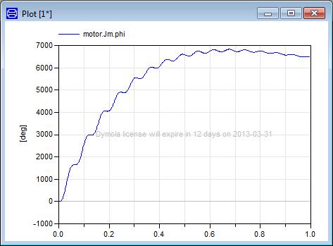
41 3.4.3 Minor improvements Checking out license options from a license server improved In Dymola 2014 the check-out of the Model Management option can be disabled. By default, the option is not checked out. The setting corresponds to the flag Advanced.EnableModelManagement=false The setting is saved between sessions. Warning of license expiration During the last 30 days before expiration, a warning message that the license will soon expire will be displayed like a water mark in all models. Some examples: Dymola 2014 Release notes 41
42 42
43 3.5 Other Simulation Environments Dymola Matlab interface Compatibility The Dymola Simulink interface now supports Matlab releases from R2008a (ver. 7.6) up to R2012b (ver. 8.0). Only Visual Studio C++ compilers are supported to generate the DymolaBlock S-function. The LCC compiler is not supported. All encrypted files in the Dymola/Mfiles folder are now p-coded with the most recent version. Thus, it is no longer necessary to switch off warnings about old p-code version. The line below can be removed from the Matlab startup script: warning('off', 'MATLAB:oldPfileVersion'); Real-time simulation Compatibility dspace Dymola 2014 generated code has been verified for compatibility with the following combinations of dspace and Matlab releases on the DS1005 and DS1006 platforms dspace Release 6.2 (RTI 6.1) with Matlab R2008a dspace Release 6.3 (RTI 6.2) with Matlab R2008b dspace Release 6.4 (RTI 6.3) with Matlab R2009a dspace Release 6.6 (RTI 6.5) with Matlab R2010a dspace Release 7.0 (RTI 6.6) with Matlab R2009bSP1 and R2010bSP1 dspace Release 7.1 (RTI 6.7) with Matlab R2011a dspace Release 7.2 (RTI 6.8) with Matlab R2011b dspace Release 7.3 (RTI 6.9) with Matlab R2011b and R2012a dspace Release 7.4 (RTI 6.9.1) with Matlab R2011b, R2012a, and R2012b The selection of supported dspace releases focuses on releases that introduce support for a new Matlab release and dspace releases that introduce a new version of a cross-compiler tool. In addition, we always support the three latest dspace releases with the three latest Matlab releases. Although not officially supported, it is likely that other combinations should work as well. Compatibility xpc Target Compatibility with Matlab xpc Target has been verified for all Matlab releases that are supported by the Dymola Simulink interface, which means R2008a (xpc Target ver. 3.4) to R2012b (xpc Target ver. 5.3). Only Microsoft Visual C compilers have been tested. Dymola 2014 Release notes 43
44 3.5.3 FMI Support in Dymola Support for FMI 2.0 beta 4 All mandatory features are supported in FMI 2.0 Beta 4. The optional (in the sense that they have associated capability flags) features not supported are: FMUs can only be instantiated once per process. The internal FMU state cannot be serialized. fmidostep cannot run asynchronously, i.e. fmipending is never returned. The Files > Import > FMU commands and script function importfmu accepts FMUs created according to FMI 2.0 Beta 4 Model Exchange specification. Current supported features are the same as for FMI 1.0. When exporting, the version to be generated can be set in the FMI tab using the command Simulation > Setup, see figure below. When using scripting, the built-in function translatemodelfmu now has a new string argument fmiversion that controls the FMI version ("1" or "2") of the FMU. The default is "1". Use of export option visible in the generated FMU In Dymola 2014 the generated FMU contains information telling if it has been generated without the binary export option. In that case, the following text is generated in the XML file: generationtool="dymola Version 2014 (64-bit), (requires license to execute)" Improved source code export in FMUs Handling multiple FMUs In Dymola 2014 an extra source file, all.c, is provided; it includes all other C files. This file is needed to compile all FMUs source code as one unit, which in turn is required because the demand that all internal functions and symbols needs to be static to be able to combine several source code FMUs. The only disadvantage compiling this file instead of the separate C files, is that any modification in any source code file requires re-compilation of everything. Improved GUI for FMI settings The previous FMI Export tab has been renamed and extended. General FMI settings are now collected in the FMI tab, available with the command Simulation > Setup, the FMI tab: 44

45 Both FMI import settings and FMI export settings are now included. Concerning the Preferred type group for import, the preferred import type is only relevant if the imported FMU supports both model exchange and co-simulation. Otherwise this setting is silently ignored. Import of FMU files by dragging them into Dymola main window supported. FMU files (.fmu) that are dragged into the Dymola main window are automatically imported like performing the command File > Import > FMU on the file. Dymola 2014 Release notes 45
46 Location of imported FMU selectable Importing an FMU, the location (package) to import it to can be selected using the input string parameter packagename in the built-in function importfmu. The package must be open in Dymola when importing. Note that presently this functionality is only available using scripting Code and Model Export Code and model export template available on Linux The template project StandAloneDymosim that describes how to interface models exported with Binary Model Export or Source Code Generation to standard integration routines, to build stand-alone applications, is now also available on Linux. 3.6 Advanced Modelica Support Synchronous Modelica The synchronous features of Modelica 3.3 are supported. References to papers describing these features are available using the command Help > Documentation. A tutorial is also available using the command Help > Demos > Synchronous Tutorial. The tutorial relates to the papers and presentations mentioned State Machines The State Machines of Modelica 3.3 are supported. References to papers describing these features are available using the command Help > Documentation. A tutorial is also available using the command Help > Demos > Synchronous Tutorial. The tutorial relates to the papers and presentations mentioned Minor improvements Quoted identifiers containing dot supported Quoted identifiers containing dot are now supported, including Class and component names Hierarchical modifiers Variable browser Import Derivative names It is recommended to avoid using embedded dot for top-level classes; the file names will not be nice. 46
47 3.7 New libraries Modelica_Synchronous library The library Modelica_Synchronous is a Modelica package to precisely define and synchronize sampled data systems with different sampling rates. The library has elements to define periodic clocks and event clocks that trigger elements to sample, sub-sample, supersample, or shift-sample partitions synchronously. Optionally, quantization effects, computational delay or noise can be simulated. Continuous-time equations can be automatically discretized and utilized in a sampled data system. The sample rate of a partition needs to be defined at one location only. All Modelica libraries designed so far for sampled systems, such as Modelica.Blocks.Discrete or Modelica_LinearSystems2.Controller are becoming obsolete and instead Modelica_Synchronous should be utilized instead. 3.8 Updated libraries AirConditioning Library A minor version, 1.8.4, has been released, with some robustness improvements and component modifications Engine Dynamics Library Version 1.1 is a major update of the Engine Dynamics Library. Several new components have been added to facilitate creation of engine systems with very few states. Such models may be desirable in order to improve simulation speed of desktop simulations and SIL applications, and are suitable to linearize in case the model should be used for model based control system development. The new components are: A set of new components that assumes quasi-static temperature and positive flow rate. Specialized turbo components that use a custom rotational connector including only the angular velocity and cut torque. An engine template using the simplified components. Other new components have been added as well, and other improvements have been made. Conversion from older models can be made automatically Hydraulics Library A minor version, 3.3.1, has been released, with minor improvements. Dymola 2014 Release notes 47
48 3.8.4 Hydro Power Library Hydro Power Library version 2.2 contains several major improvements. The largest change is the introduction of the system component System_HPL. A system component is now needed in each model to provide system-wide settings, such as modeling assumptions and default values. The system settings are propagated to the fluid models using the inner/outer mechanism. Model assumptions such as constant temperature or steady-state initialization can now be turned on/off globally instead of having to modify all components locally. A major speedup has been obtained by a more efficient friction implementation. Other improvements are improved documentation, new icon visualization, more descriptive model names, and new visualizer objects. Models not older than of version HydroPlant can be automatically converted. Older plants may need some manual conversion Liquid Cooling Library Version 1.1 of the Liquid Cooling library is a major release. Several new internal flow components have been added with geometry based flow resistance models; e.g. straight pipes, bend, orifice plate, intake, junction combining/dividing components. Other new components have been added as well. Medium property models for several liquid phase coolants and refrigerants have been added. The concentration can be set to any value between zero and the eutectic point for the given mixture and is valid between the freezing point and boiling point of the fluid. Templates and examples that illustrate how to create simple automotive heat exchanger stack models are available. Other features and improvements are implemented as well. Conversion of older models can be done automatically. Note that users of the table based, fixed water glycol mixtures will be converted to medium models using IIF reference data Optimization Library A new major version 2.2 of the library is available. The following have been implemented: Advanced parallel simulation runs: o Parallel Multi simulation. o Parallel simulation on a distributed Linux cluster. o Simulation package to use parallel simulations independently of optimization runs. Extended task Trajectory Optimization: o Support of free end time problems. o Start and end conditions (also derivatives) of control functions. o Separate additional tuners (e.g. initial values of states). Improved Optimization algorithms: o Genetic algorithm uses parallel simulation runs. 48

49 o o Simplex method can handle equality constraints. Improved Pattern search algorithm. The version is backward compatible to optimization setups of versions 2.0 and 2.1. A menu for some of the most frequent optimization functions is automatically displayed in Dymola when opening the library: Pneumatics Library Version 1.6 of the Pneumatics Library is a minor release, with documentation inserted in the library as html files from the previous manual, and some library additions, like mass flow rate source Thermal Power Library Version 1.6 is a major release of Thermal Power library. Several major improvements have been implemented. New pressure boundary models have been added, as well as new flow boundary models. New HeatExchanger packages have been created. Level visualization, temperature visualization, added sensors, improved documentation and more is available for a number of components. A number of components have been renamed. Conversion from older models can be made automatically Vehicle Dynamics Library A minor maintenance version has been released. Some example experiments have been improved by using the Modelon.DataAccess package. Animation view commands have been added to many experiments to modify the animation view in the active animation window. 3.9 Documentation In the software distribution of Dymola 2014 Dymola User Manuals of version March 2013 will be present; these manuals include all relevant features/improvements of Dymola 2014 presented in the Release notes. Limited Availability (LA) features are not included. Dymola 2014 Release notes 49
FMI Kit for Simulink version by Dassault Systèmes
 FMI Kit for Simulink version 2.4.0 by Dassault Systèmes April 2017 The information in this document is subject to change without notice. Copyright 1992-2017 by Dassault Systèmes AB. All rights reserved.
WinView. Getting Started Guide
 WinView Getting Started Guide Version 4.3.12 June 2006 Copyright 2006 Mincom Limited All rights reserved. No part of this document may be reproduced, transferred, sold or otherwise disposed of without
Tutorial 3: Using the Waveform Viewer Introduces the basics of using the waveform viewer. Read Tutorial SIMPLIS Tutorials SIMPLIS provide a range of t
 Tutorials Introductory Tutorials These tutorials are designed to give new users a basic understanding of how to use SIMetrix and SIMetrix/SIMPLIS. Tutorial 1: Getting Started Guides you through getting
FMI WORKSHOP. INCOSE International Workshop, Los Angeles, CA, Contents. Introduction
 FMI WORKSHOP INCOSE International Workshop, Los Angeles, CA, 2015 Contents Introduction...1 Model Overview...2 Model Systems...2 Model Features...3 Key Parameters...6 File Structure...6 Demonstration:
The Mathcad Workspace 7
 For information on system requirements and how to install Mathcad on your computer, refer to Chapter 1, Welcome to Mathcad. When you start Mathcad, you ll see a window like that shown in Figure 2-1. By
Logger Pro 3. Quick Reference
 Logger Pro 3 Quick Reference Getting Started Logger Pro Requirements To use Logger Pro, you must have the following equipment: Windows 98, 2000, ME, NT, or XP on a Pentium processor or equivalent, 133
Dymola Dynamic Modeling Laboratory
 Dymola Dynamic Modeling Laboratory FMI Support in Dymola Contents: Section FMI Support in Dymola from Chapter 6 Other Simulation Environments from the manual Dymola User Manual Volume 2. March 2018 (Dymola
Session 3 Introduction to SIMULINK
 Session 3 Introduction to SIMULINK Brian Daku Department of Electrical Engineering University of Saskatchewan email: daku@engr.usask.ca EE 290 Brian Daku Outline This section covers some basic concepts
MapleSim User's Guide
 MapleSim User's Guide Copyright Maplesoft, a division of Waterloo Maple Inc. 2001-2009 MapleSim User's Guide Copyright Maplesoft, MapleSim, and Maple are all trademarks of Waterloo Maple Inc. Maplesoft,
Piping & Instrumentation Diagrams
 Page 1 Piping & Instrumentation Diagrams Preface Using This Guide What's New? Getting Started Entering the Workbench Setting up Working Units and Grid Placing Components Routing a Piping Line or I & C
Selective Space Structures Manual
 Selective Space Structures Manual February 2017 CONTENTS 1 Contents 1 Overview and Concept 4 1.1 General Concept........................... 4 1.2 Modules................................ 6 2 The 3S Generator
Thermo Scientific. GRAMS Envision. Version 2.1. User Guide
 Thermo Scientific GRAMS Envision Version 2.1 User Guide 2013 Thermo Fisher Scientific Inc. All rights reserved. Thermo Fisher Scientific Inc. provides this document to its customers with a product purchase
OpenForms360 Validation User Guide Notable Solutions Inc.
 OpenForms360 Validation User Guide 2011 Notable Solutions Inc. 1 T A B L E O F C O N T EN T S Introduction...5 What is OpenForms360 Validation?... 5 Using OpenForms360 Validation... 5 Features at a glance...
Numbers Basics Website:
 Website: http://etc.usf.edu/te/ Numbers is Apple's new spreadsheet application. It is installed as part of the iwork suite, which also includes the word processing program Pages and the presentation program
Excel Select a template category in the Office.com Templates section. 5. Click the Download button.
 Microsoft QUICK Excel 2010 Source Getting Started The Excel Window u v w z Creating a New Blank Workbook 2. Select New in the left pane. 3. Select the Blank workbook template in the Available Templates
Thermal Transient Test Installation and Operating Manual
 Thermal Transient Test Installation and Operating Manual 2705A De La Vina Street Santa Barbara, California 93105 Telephone (805) 682-0900 descon@silcom.com www. santabarbaraautomation.com Installation
Piping & Instrumentation Diagrams
 Piping & Instrumentation Diagrams Preface Using This Guide What's New? Getting Started Entering the Workbench Setting up Working Units and Grid Placing Components Routing a Piping Line or I & C Loop Placing
GET TO KNOW FLEXPRO IN ONLY 15 MINUTES
 GET TO KNOW FLEXPRO IN ONLY 15 MINUTES Data Analysis and Presentation Software GET TO KNOW FLEXPRO IN ONLY 15 MINUTES This tutorial provides you with a brief overview of the structure of FlexPro and the
SUM - This says to add together cells F28 through F35. Notice that it will show your result is
 COUNTA - The COUNTA function will examine a set of cells and tell you how many cells are not empty. In this example, Excel analyzed 19 cells and found that only 18 were not empty. COUNTBLANK - The COUNTBLANK
Dymola Dynamic Modeling Laboratory. Dymola Release Notes
 Dymola Dynamic Modeling Laboratory Dymola Release Notes Dymola 2018 The information in this document is subject to change without notice. Document version: 1 Copyright 1992-2017 by Dassault Systèmes AB.
User's Guide. For CarChip and CarChip E/X 8210 & 8220
 User's Guide TM For CarChip and CarChip E/X 8210 & 8220 Product Number: 8210, 8220 Davis Instruments Part Number: 7395.064 DriveRight CarChip User s Manual Rev A (January 2, 2003) Davis Instruments Corp.,
for Q-CHECKER Text version 15-Feb-16 4:49 PM
 Q-MONITOR 5.4.X FOR V5 for Q-CHECKER USERS GUIDE Text version 15-Feb-16 4:49 PM Orientation Symbols used in the manual For better orientation in the manual the following symbols are used: Warning symbol
CHAPTER 4: MICROSOFT OFFICE: EXCEL 2010
 CHAPTER 4: MICROSOFT OFFICE: EXCEL 2010 Quick Summary A workbook an Excel document that stores data contains one or more pages called a worksheet. A worksheet or spreadsheet is stored in a workbook, and
Dymola Dynamic Modeling Laboratory
 Dymola Dynamic Modeling Laboratory FMI Support in Dymola Contents: Section FMI Support in Dymola from Chapter 6 Other Simulation Environments from the manual Dymola User Manual Volume 2. March 2017 (Dymola
ChemSense Studio Client Version 3.0.7
 Quick Start Guide: ChemSense Studio Client Version 3.0.7 January 5, 2005 Comments/Questions/Bug Report? E-mail: chemsense-contact@ctl.sri.com Background The ChemSense Studio Client software supports the
Tutorial 1 Getting Started
 by Tutorial 1 Getting Started Objective The following tutorial is a step-by-step introduction to the basics of SimulationX. You will first get an overview of the graphical user interface (GUI) with the
AEMLog Users Guide. Version 1.01
 AEMLog Users Guide Version 1.01 INTRODUCTION...2 DOCUMENTATION...2 INSTALLING AEMLOG...4 AEMLOG QUICK REFERENCE...5 THE MAIN GRAPH SCREEN...5 MENU COMMANDS...6 File Menu...6 Graph Menu...7 Analysis Menu...8
Introduction to Excel 2007
 Introduction to Excel 2007 These documents are based on and developed from information published in the LTS Online Help Collection (www.uwec.edu/help) developed by the University of Wisconsin Eau Claire
4 TRANSFORMING OBJECTS
 4 TRANSFORMING OBJECTS Lesson overview In this lesson, you ll learn how to do the following: Add, edit, rename, and reorder artboards in an existing document. Navigate artboards. Select individual objects,
UNIVERSITI TEKNIKAL MALAYSIA MELAKA FAKULTI KEJURUTERAAN ELEKTRONIK DAN KEJURUTERAAN KOMPUTER
 UNIVERSITI TEKNIKAL MALAYSIA MELAKA FAKULTI KEJURUTERAAN ELEKTRONIK DAN KEJURUTERAAN KOMPUTER FAKULTI KEJURUTERAAN ELEKTRONIK DAN KEJURUTERAAN KOMPUTER BENC 2113 DENC ECADD 2532 ECADD LAB SESSION 6/7 LAB
Importing Models from Physical Modeling. Tools Using the FMI Standard
 Importing Models from Physical Modeling Tools Using the FMI Standard Overview The objective of this tutorial is to demonstrate the workflow for the integration of FMUs in DYNA4. The following use case
Visual Dialogue User Guide. Version 6.0
 Visual Dialogue User Guide Version 6.0 2013 Pitney Bowes Software Inc. All rights reserved. This document may contain confidential and proprietary information belonging to Pitney Bowes Inc. and/or its
Microsoft How to Series
 Microsoft How to Series Getting Started with EXCEL 2007 A B C D E F Tabs Introduction to the Excel 2007 Interface The Excel 2007 Interface is comprised of several elements, with four main parts: Office
motcom loganalyser User Manual
 User Manual Part No. 2 900 04 10000 Release 07.03.2016 English revision 160825 Kurt-Schumacher-Str. 28-30 66130 Saarbrücken, Germany e-mail: info@motcomgmbh.com web: www.motcomgmbh.com Contents Introduction...
Impress Guide. Chapter 11 Setting Up and Customizing Impress
 Impress Guide Chapter 11 Setting Up and Customizing Impress Copyright This document is Copyright 2007 2013 by its contributors as listed below. You may distribute it and/or modify it under the terms of
VeriStand. FMI to NI VeriStand Add-on. User Guide
 MI To NI VeriStand F FMI to NI VeriStand Add-on User Guide 2 FMI To NI VeriStand Import FMU Model in NI VeriStand FMI To NI VeriStand Add-on Release 1.5.1 3 The information in this document is subject
Multichannel Data logging
 Multichannel Data logging As of version V1.1 Operating manual Bedienungsanleitung EBS 20M / EBS 60M SYSTEM REQUIREMENTS... 3 SCOPE OF SUPPLY... 3 INSTALLATION AND COMMISSIONING... 3 DESIGNATED USE... 3
SequencePro Data Analysis Application. User Guide
 SequencePro Data Analysis Application User Guide SequencePro Data Analysis Application User Guide DRAFT October 31, 2001 12:52 pm, Title_page.fm Copyright 2001, Applied Biosystems. All rights reserved.
Insight: Measurement Tool. User Guide
 OMERO Beta v2.2: Measurement Tool User Guide - 1 - October 2007 Insight: Measurement Tool User Guide Open Microscopy Environment: http://www.openmicroscopy.org OMERO Beta v2.2: Measurement Tool User Guide
Manual. empower charts 6.4
 Manual empower charts 6.4 Contents 1 Introduction... 1 2 Installation, updates and troubleshooting... 1 2.1 System requirements... 1 2.2 Initial installation... 1 2.3 Installation of an update... 1 2.4
Electrical 3D Design & Documentation
 Electrical 3D Design & Documentation Page 1 Overview Conventions User Tasks Using Electrical 3D Design & Documentation Entering the Electrical Assembly Design Workbench Entering the Electrical Part Design
3.2 Circle Charts Line Charts Gantt Chart Inserting Gantt charts Adjusting the date section...
 / / / Page 0 Contents Installation, updates & troubleshooting... 1 1.1 System requirements... 2 1.2 Initial installation... 2 1.3 Installation of an update... 2 1.4 Troubleshooting... 2 empower charts...
Vensim PLE Quick Reference and Tutorial
 Vensim PLE Quick Reference and Tutorial Main Toolbar Sketch Tools Menu Title Bar Analysis Tools Build (Sketch)Window Status Bar General Points 1. File operations and cutting/pasting work in the standard
Desktop Studio: Charts
 Desktop Studio: Charts Intellicus Enterprise Reporting and BI Platform Intellicus Technologies info@intellicus.com www.intellicus.com Working with Charts i Copyright 2011 Intellicus Technologies This document
Desktop Studio: Charts. Version: 7.3
 Desktop Studio: Charts Version: 7.3 Copyright 2015 Intellicus Technologies This document and its content is copyrighted material of Intellicus Technologies. The content may not be copied or derived from,
Microsoft Excel 2010 Tutorial
 1 Microsoft Excel 2010 Tutorial Excel is a spreadsheet program in the Microsoft Office system. You can use Excel to create and format workbooks (a collection of spreadsheets) in order to analyze data and
INTRODUCTION... 1 UNDERSTANDING CELLS... 2 CELL CONTENT... 4
 Introduction to Microsoft Excel 2016 INTRODUCTION... 1 The Excel 2016 Environment... 1 Worksheet Views... 2 UNDERSTANDING CELLS... 2 Select a Cell Range... 3 CELL CONTENT... 4 Enter and Edit Data... 4
AEMLog users guide V User Guide - Advanced Engine Management 2205 West 126 th st Hawthorne CA,
 AEMLog users guide V 1.00 User Guide - Advanced Engine Management 2205 West 126 th st Hawthorne CA, 90250 310-484-2322 INTRODUCTION...2 DOCUMENTATION...2 INSTALLING AEMLOG...4 TRANSFERRING DATA TO AND
ECDL Module 4 REFERENCE MANUAL
 ECDL Module 4 REFERENCE MANUAL Spreadsheets Microsoft Excel XP Edition for ECDL Syllabus Four PAGE 2 - ECDL MODULE 4 (USING MICROSOFT EXCEL XP) - MANUAL 4.1 USING THE APPLICATION... 4 4.1.1 FIRST STEPS
Excel Tutorial 1
 IT٢.we Excel 2003 - Tutorial 1 Spreadsheet Basics Screen Layout Title bar Menu bar Standard Toolbar Other Tools Task Pane Adding and Renaming Worksheets Modifying Worksheets Moving Through Cells Adding
Using the New Profile Editor
 Using the New Profile Editor Introduction Welcome to the new motion profile editor for Motion Analyzer Online! We ve gathered a lot of feedback from our users and have incorporated it into the latest release.
FMI Toolbox User's Guide 2.6.4
 FMI Toolbox User's Guide 2.6.4 FMI Toolbox User's Guide 2.6.4 Publication date 2018-07-23 Copyright 2018 Modelon AB Ideon Science Park SE-22370 LUND Self publishing ALL RIGHTS RESERVED.
USER GUIDE. We hope you enjoy using the product, and please don t hesitate to send us questions or provide feedback at Thank You.
 USER GUIDE Introduction This User Guide is designed to serve as a brief overview to help you get started. There is also information available under the Help option in the various Contributor interface
Getting Started with LabVIEW Virtual Instruments
 Getting Started with LabVIEW Virtual Instruments Approximate Time You can complete this exercise in approximately 30 minutes. Background LabVIEW programs are called virtual instruments, or VIs, because
Microsoft Excel 2010 Handout
 Microsoft Excel 2010 Handout Excel is an electronic spreadsheet program you can use to enter and organize data, and perform a wide variety of number crunching tasks. Excel helps you organize and track
Solo 4.6 Release Notes
 June9, 2017 (Updated to include Solo 4.6.4 changes) Solo 4.6 Release Notes This release contains a number of new features, as well as enhancements to the user interface and overall performance. Together
INTRODUCTION TO THE MATLAB APPLICATION DESIGNER EXERCISES
 INTRODUCTION TO THE MATLAB APPLICATION DESIGNER EXERCISES Eric Peasley, Department of Engineering Science, University of Oxford version 4.6, 2018 MATLAB Application Exercises In these exercises you will
News in RSA-RTE 10.2 updated for sprint Mattias Mohlin, May 2018
 News in RSA-RTE 10.2 updated for sprint 2018.18 Mattias Mohlin, May 2018 Overview Now based on Eclipse Oxygen.3 (4.7.3) Contains everything from RSARTE 10.1 and also additional features and bug fixes See
RK4. Version 3.0. (updated 12/1/2006) 2001, 2005, 2006 Tomas Co. Michigan Technological University Houghton, MI 49931
 2001, 2005, 2006 Tomas Co. Michigan Technological University Houghton, MI 49931") RK4 Version 3.0 (updated 12/1/2006) 2001, 2005, 2006 Tomas Co Michigan Technological University Houghton, MI 49931 Table of Contents Description 3 Rationale 3 Special Features 3 Installing the RK4 Add-In
RK4 Version 3.0 (updated 12/1/2006) 2001, 2005, 2006 Tomas Co Michigan Technological University Houghton, MI 49931 Table of Contents Description 3 Rationale 3 Special Features 3 Installing the RK4 Add-In
Quick Start Training Guide
 Quick Start Training Guide Table of Contents 1 INTRODUCTION TO MAPLESIM... 5 1.1 USER INTERFACE... 5 2 WORKING WITH A SAMPLE MODEL... 7 2.1 RUNNING A SIMULATION... 7 2.2 GRAPHICAL OUTPUT... 7 2.3 3D VISUALIZATION...
Navigator Software User s Manual. User Manual. Navigator Software. Monarch Instrument Rev 0.98 May Page 1 of 17
 User Manual Navigator Software Monarch Instrument Rev 0.98 May 2006 Page 1 of 17 Contents 1. NAVIGATOR SOFTWARE 2. INSTALLATION 3. USING NAVIGATOR SOFTWARE 3.1 STARTING THE PROGRAM 3.2 SYSTEM SET UP 3.3
Dymola Dynamic Modeling Laboratory
 Dymola Dynamic Modeling Laboratory Dymola Release Notes Dymola 2018 FD01 The information in this document is subject to change without notice. Document version: 1 Copyright 1992-2017 by Dassault Systèmes
User Guide Product Design Version 1.7
 User Guide Product Design Version 1.7 1 INTRODUCTION 3 Guide 3 USING THE SYSTEM 4 Accessing the System 5 Logging In Using an Access Email 5 Normal Login 6 Resetting a Password 6 Logging Off 6 Home Page
Experiment 3. Getting Start with Simulink
 Experiment 3 Getting Start with Simulink Objectives : By the end of this experiment, the student should be able to: 1. Build and simulate simple system model using Simulink 2. Use Simulink test and measurement
DRAFT. Table of Contents About this manual... ix About CuteSITE Builder... ix. Getting Started... 1
 DRAFT Table of Contents About this manual... ix About CuteSITE Builder... ix Getting Started... 1 Setting up... 1 System Requirements... 1 To install CuteSITE Builder... 1 To register CuteSITE Builder...
Getting Started with the MapleSim FMI Connector
 Getting Started with the MapleSim FMI Connector Copyright Maplesoft, a division of Waterloo Maple Inc. 2017 Getting Started with the MapleSim FMI Connector Copyright Maplesoft, Maple, and MapleSim are
StruSoft StruXML Revit Add-In Manual: Using Revit FEM-Design link
 StruSoft StruXML Revit Add-In Manual: Using Revit FEM-Design link StruSoft AB Fridhemsvägen 22 SE-217 74, Malmö, Sweden www.strusoft.com Version: January 4th, 2017 Copyright Copyright 2017 by StruSoft.
Multi-Physics RecurDyn Style Interoperability
 Multi-Physics RecurDyn Style Interoperability Brant Ross 1. System-Level Simulation 1.Multi-disciplinary Simulation Multiphysics for Fluid Structure Interaction Multiphysics = Any combination of CAE Multiphysics
Adobe Acrobat Reader 4.05
 Adobe Acrobat Reader 4.05 1. Installing Adobe Acrobat Reader 4.05 If you already have Adobe Acrobat Reader installed on your computer, please ensure that it is version 4.05 and that it is Adobe Acrobat
file://c:\documents and Settings\degrysep\Local Settings\Temp\~hh607E.htm
 Page 1 of 18 Trace Tutorial Overview The objective of this tutorial is to acquaint you with the basic use of the Trace System software. The Trace System software includes the following: The Trace Control
A Guide to Quark Author Web Edition 2015
 A Guide to Quark Author Web Edition 2015 CONTENTS Contents Getting Started...4 About Quark Author - Web Edition...4 Smart documents...4 Introduction to the Quark Author - Web Edition User Guide...4 Quark
Testing and Diagnostics
 Scope 3 Overview in real-time Signal analytics and diagnostics directly with the controller In the initial project design and also for commissioning or troubleshooting, transparent information concerning
W-E
 Signage Suite V2.20 User Guide 605220-02-01-W-E-051613-02 Trademarks Windows XP, Windows Vista, Windows 7, and Microsoft are registered trademarks of Microsoft Corporation. All other trademarks are the
L E S S O N 2 Background
 Flight, Naperville Central High School, Naperville, Ill. No hard hat needed in the InDesign work area Once you learn the concepts of good page design, and you learn how to use InDesign, you are limited
End User Guide. 2.1 Getting Started Toolbar Right-click Contextual Menu Navigation Panels... 2
 TABLE OF CONTENTS 1 OVERVIEW...1 2 WEB VIEWER DEMO ON DESKTOP...1 2.1 Getting Started... 1 2.1.1 Toolbar... 1 2.1.2 Right-click Contextual Menu... 2 2.1.3 Navigation Panels... 2 2.1.4 Floating Toolbar...
Flow Cytometry Analysis Software. Developed by scientists, for scientists. User Manual. Version Introduction:
 Flowlogic Flow Cytometry Analysis Software Developed by scientists, for scientists User Manual Version 7.2.1 Introduction: Overview, Preferences, Saving and Opening Analysis Files www.inivai.com TABLE
Labview. Masood Ejaz
 Labview A Tutorial By Masood Ejaz Note: This tutorial is a work in progress and written specially for CET 3464 Software Applications in Engineering Technology, a course offered as part of BSECET program
Sending image(s) to report Click Send Snapshot on any screen in Dolphin3D and choose the Send to Report option
 to report Click Send Snapshot on any screen in Dolphin3D and choose the Send to Report option") Dolphin 3D Reports Sending image(s) to report Click Send Snapshot on any screen in Dolphin3D and choose the Send to Report option Creating a report step by step 1. Generate the desired images in Dolphin3D
Dolphin 3D Reports Sending image(s) to report Click Send Snapshot on any screen in Dolphin3D and choose the Send to Report option Creating a report step by step 1. Generate the desired images in Dolphin3D
IBM Rational Rhapsody Gateway Add On. User Guide
 User Guide Rhapsody IBM Rational Rhapsody Gateway Add On User Guide License Agreement No part of this publication may be reproduced, transmitted, stored in a retrieval system, nor translated into any
CHAPTER 1 COPYRIGHTED MATERIAL. Getting to Know AutoCAD. Opening a new drawing. Getting familiar with the AutoCAD and AutoCAD LT Graphics windows
 CHAPTER 1 Getting to Know AutoCAD Opening a new drawing Getting familiar with the AutoCAD and AutoCAD LT Graphics windows Modifying the display Displaying and arranging toolbars COPYRIGHTED MATERIAL 2
Scheme Editor. Version 6.3. Manual Edition 1
 Scheme Editor Version 6.3 Manual Edition 1 Bosch Rexroth AG Print Title Type of Documentation Document Typecode Internal File Reference Scheme Editor Version 6.3 Manual Print RS-0361ea845ef863400a6846a0010a9c70-19-en-US-3
MS Office for Engineers
 MS Office for Engineers Lesson 4 Excel 2 Pre-reqs/Technical Skills Basic knowledge of Excel Completion of Excel 1 tutorial Basic computer use Expectations Read lesson material Implement steps in software
Introducing Gupta Report Builder
 Business Reporting Chapter 1 Introducing Gupta Report Builder You can use Report Builder to design reports. This chapter describes: Our approach to building reports. Some of the reports you can build.
Impress Guide Chapter 11 Setting Up and Customizing Impress
 Impress Guide Chapter 11 Setting Up and Customizing Impress This PDF is designed to be read onscreen, two pages at a time. If you want to print a copy, your PDF viewer should have an option for printing
Process Eye Professional. Recall
 Process Eye Professional Recall Process Eye Professional Recall User Manual SP104010.101 August 2005 As part of our continuous product improvement policy, we are always pleased to receive your comments
N2KExtractor. Maretron Data Extraction Software User s Manual
 N2KExtractor Maretron Data Extraction Software User s Manual Revision 3.1.6 Copyright 2017 Maretron, LLP All Rights Reserved Maretron, LLP 9014 N. 23rd Ave #10 Phoenix, AZ 85021-7850 http://www.maretron.com
AgWare ClickFORMS 7.0 Introductory Tutorial
 AgWare ClickFORMS 7.0 Introductory Tutorial MAIN WINDOW If you have used Office 2007, our new layout will look familiar. Here is a screenshot of the new and improved AgWare ClickFORMS window: The Forms
2010 by Microtek International, Inc. All rights reserved.
 2010 by Microtek International, Inc. All rights reserved. Microtek and DocWizard are trademarks of Microtek International, Inc. Windows is a registered trademark of Microsoft Corporation. All other products
Tetra4D Reviewer. Version 5.1. User Guide. Details on how to use Tetra4D Reviewer.
 Tetra4D Reviewer Version 5.1 User Guide Details on how to use Tetra4D Reviewer. ii Contents Chapter 1: Work area... 7 Looking at the work area... 7 Toolbars and toolbar presets... 8 About toolbars and
ezimagex2 User s Guide Version 1.0
 ezimagex2 User s Guide Version 1.0 Copyright and Trademark Information The products described in this document are copyrighted works of AVEN, Inc. 2015 AVEN, Inc. 4595 Platt Rd Ann Arbor, MI 48108 All
Introduction to Simulink. The Use of Mathematic Simulations in Electrical Engineering
 Introduction to Simulink The Use of Mathematic Simulations in Electrical Engineering Lecture Outline 1) Introduction to Simulink 2) Modelling of dynamics systems 2 Simulink Tool for modeling, simulating,
Adding Dynamics. Introduction
 M-Graphic s User s Manual 11-1 Chapter 11 Adding Dynamics Introduction This chapter explains how to make single or multiple dynamic connections from display objects to points from OPC data servers. This
Heat Exchanger Efficiency
 6 Heat Exchanger Efficiency Flow Simulation can be used to study the fluid flow and heat transfer for a wide variety of engineering equipment. In this example we use Flow Simulation to determine the efficiency
FMI to NI VeriStand & LabVIEW Add-on. User Guide
 F FMI to NI VeriStand & LabVIEW Add-on User Guide 2 FMI To NI VeriStand & LabVIEW User Guide - 3 - FMI To NI VeriStand & LabVIEW Import FMU Model in NI VeriStand and LabVIEW FMI To NI VeriStand & LabVIEW
The American University in Cairo. Academic Computing Services. Word prepared by. Soumaia Ahmed Al Ayyat
 The American University in Cairo Academic Computing Services Word 2000 prepared by Soumaia Ahmed Al Ayyat Spring 2001 Table of Contents: Opening the Word Program Creating, Opening, and Saving Documents
Microsoft Office Excel
 Microsoft Office 2007 - Excel Help Click on the Microsoft Office Excel Help button in the top right corner. Type the desired word in the search box and then press the Enter key. Choose the desired topic
SAS Visual Analytics 8.2: Working with Report Content
 SAS Visual Analytics 8.2: Working with Report Content About Objects After selecting your data source and data items, add one or more objects to display the results. SAS Visual Analytics provides objects
LabVIEW Express VI Development Toolkit User Guide
 LabVIEW Express VI Development Toolkit User Guide Version 1.0 Contents The LabVIEW Express VI Development Toolkit allows you to create and edit Express VIs, which you can distribute to users for building
HVAC Diagrams Preface What's New? Getting Started User Tasks
 HVAC Diagrams Preface Using This Guide What's New? Getting Started Entering the Workbench Setting up Working Units and Grid Placing Components Routing an HVAC Line Placing Components in a Line Repositioning
Microsoft PowerPoint 2007 Tutorial
 Microsoft PowerPoint 2007 Tutorial Prepared By:- Mohammad Murtaza Khan I. T. Expert Sindh Judicial Academy Contents Getting Started... 5 Presentations... 5 Microsoft Office Button... 5 Ribbon... 6 Quick