Modeling and Verifying Mixed-Signal Designs with MATLAB and Simulink
|
|
|
- Paulina McLaughlin
- 6 years ago
- Views:
Transcription

1 Modeling and Verifying Mixed-Signal Designs with MATLAB and Simulink Arun Mulpur, Ph.D., MBA Industry Group Manager Communications, Electronics, Semiconductors, Software, Internet Energy Production, Medical Devices, Robotics 2014 MathWorks, Inc. 1
2 Mixed-Signal Design and Verification Challenges Difficult design trade-offs SPECIFICATION Limited analog design abstractions DIGITAL DESIGN ANALOG DESIGN Limited analog/digital links Slow design iterations IMPLEMENTATION IMPLEMENTATION VHDL, Verilog Spice-like PROTOTYPE / INTEGRATION TEST & VERIFICATION Specification isolated from verification Disconnected teams 2
3 Focus on Algorithm Design Rapid design construction SPECIFICATION Easier analog modeling ANALOG & DIGITAL DESIGN Limited analog/digital links Slow design iterations IMPLEMENTATION IMPLEMENTATION VHDL, Verilog Spice-like PROTOTYPE / INTEGRATION TEST & VERIFICATION Specification isolated from verification Disconnected teams 3
4 Anticipate Impairments at System-Level Rapid design construction SPECIFICATION Easier analog modeling ANALOG & DIGITAL DESIGN Multi-domain simulation Rapid design iterations Fixed-Point Physical IMPLEMENTATION IMPLEMENTATION VHDL, Verilog Spice-like PROTOTYPE / INTEGRATION TEST & VERIFICATION Specification isolated from verification Disconnected teams 4
5 Perform Continuous Verification Rapid design construction SPECIFICATION Easier analog modeling ANALOG & DIGITAL DESIGN Multi-domain simulation IMPLEMENTATION IMPLEMENTATION TEST & VERIFICATION Integrated specification VHDL, Verilog Spice-like Rapid design iterations PROTOTYPE / INTEGRATION Improved team communication 5
6 Modeling and Verifying Mixed-Signal Designs with MATLAB and Simulink Rapid design construction SPECIFICATION Easier analog modeling ANALOG & DIGITAL DESIGN Multi-domain simulation IMPLEMENTATION IMPLEMENTATION TEST & VERIFICATION Integrated specification VHDL, Verilog Spice-like Rapid design iterations PROTOTYPE / INTEGRATION Improved team communication 6


7 Save >30% of Overall Development Time (and Improve Quality, Reduce Re-spins, etc.) With MathWorks Tools Time spent in project phases Without MathWorks Tools Requirements System Design Implementation Integration Testing Days 7
8 Recent Successes Customer Use case Atmel IDT-Newave Realtek RFMD Fujitsu RF Front End for DVB Analog-digital co-design and verification Audio chipset Rapid simulation of PLLs Voice-band codec Analog-Digital design Video transceiver System-level/SPICE cosimulation 40 Gbit/s SERDES Rapid system simulation 8
9 An Integrated Environment for Model-Based Design of Mixed-Signal Systems Saves Time and Costly Errors Algorithmic design with many trusted functions You don t have to become a modeling guru Anticipating implementation impairments / constraints Find errors early and optimize your design Building and reusing system-verification test-benches The verification effort will be limited 9
10 Design and Verification of a Sigma-Delta ADC 10
11 Goal: Preliminary Design of a Simple ADC Sigma-delta ADC Which order? Will it be stable? Analog input signal around 8kHz Design of input anti-aliasing analog filter Design of output decimation filter Tradeoff cost and performances 11


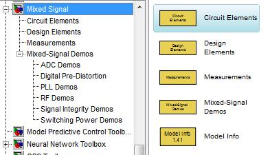
12 Mixed-Signal Modeling with Simulink Analog and digital in same model Time handling Multiple solvers / schedulers SPECIFICATION DESIGN Algorithms Digital Analog Fixed-Point Physical IMPLEMENTATION VHDL, Verilog Spice-like TEST & VERIFICATION FPGA ASIC ASIC SMPS INTEGRATION 12
13 Sigma-Delta ADC with Circuit Elements Mixed-behavioral and circuit design Include circuit elements Complex filter design SPECIFICATION DESIGN Algorithms Digital Analog Fixed-Point Physical IMPLEMENTATION VHDL, Verilog Spice-like TEST & VERIFICATION FPGA ASIC ASIC SMPS INTEGRATION 13


14 Hardware Rapid Prototyping On-target automatic HDL code generation Verification via co-simulation with third party HDL simulators SPECIFICATION DESIGN Algorithms Digital Analog Fixed-Point Physical IMPLEMENTATION VHDL, Verilog Spice-like TEST & VERIFICATION FPGA ASIC ASIC SMPS INTEGRATION 14


15 Re-Use Testbench for Verification Model refinement, implementation and verification in a single environment 15
16 An Integrated Environment for Model-Based Design of Mixed-Signal Systems Saves Time and Costly Errors Algorithmic design with many trusted functions You don t have to become a modeling guru Anticipating implementation impairments / constraints Find errors early and optimize your design Building and reusing system-verification test-benches The verification effort will be limited 16
17 Design and Verification of a PLL 17
18 Phase-Locked Loop Feedback control system Generates a signal with a fixed relation to the phase of a reference signal Used for frequency synthesis, synchronization Measurements of interest Time: rise time, overshoot, lock time, jitter Frequency: phase noise, spurs Reference Phase Detector Loop Filter VCO 1/N 18


19 PLL Key Components Digital Flip-Flop Based Phase\Frequency Detector Analog Circuit Model Charge Pump Flip-flops Delay Memory Basic Logic Resistors Capacitors Current sources 19
20 Design a 2.4 GHz ISM Band PLL Specifications: 8 channels of 10 MHz BW Integer N divider, type 2, 3 rd order PLL architecture Phase noise < 3.5 MHz offset Reference spurs < -60 dbc Lock time < 10 us Phase Margin > 60 degrees Loop filter (III order) design: Meet all specifications Minimize in-band phase noise 20
21 From Behavioral Model to Implementation Start your design in MATLAB Refine design details using behavioral circuit models Verify the specs with the refined model Link to circuit simulators to verify the behavioral models Verify the performances with the refined model Link to circuit simulators to verify the implementation 21


22 Design Exploration in MATLAB Stability analysis Step response Noise performance SPECIFICATION DESIGN Algorithms Digital Analog Fixed-Point Physical IMPLEMENTATION VHDL, Verilog Spice-like TEST & VERIFICATION FPGA ASIC ASIC SMPS INTEGRATION 22

23 Sequence of Model Elaborations Start with a basic Phase Domain linear PLL SPECIFICATION DESIGN Algorithms Digital Analog Fixed-Point Physical IMPLEMENTATION VHDL, Verilog Spice-like TEST & VERIFICATION FPGA ASIC ASIC SMPS INTEGRATION 23


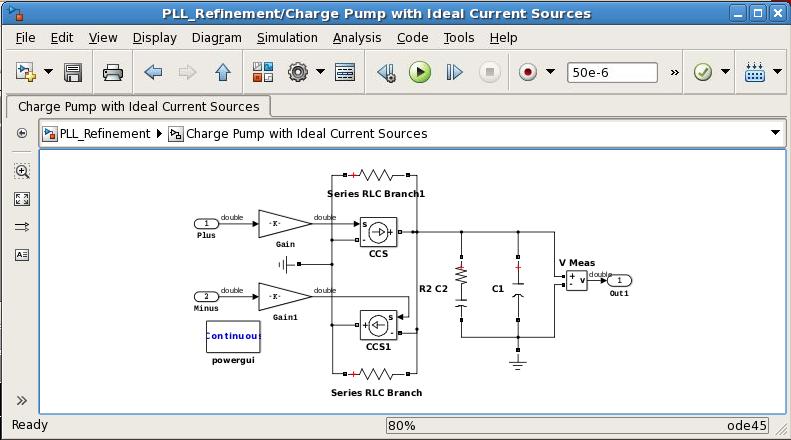
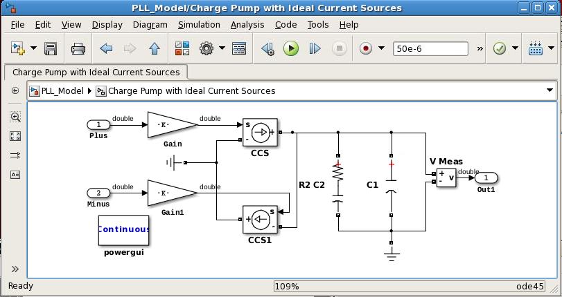
24 Laplace Representation vs. Circuit Elements Progressively refine the model and validate it using the same testbench SPECIFICATION DESIGN Algorithms Digital Analog Fixed-Point Physical IMPLEMENTATION VHDL, Verilog Spice-like TEST & VERIFICATION FPGA ASIC ASIC SMPS INTEGRATION 24

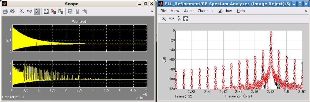
25 Converting from Phase to Time Domain Build an accurate model for spurs and phase-noise simulation SPECIFICATION DESIGN Algorithms Digital Analog Fixed-Point Physical IMPLEMENTATION VHDL, Verilog Spice-like TEST & VERIFICATION FPGA ASIC ASIC SMPS INTEGRATION 25


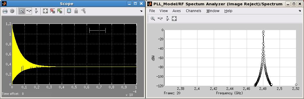
26 Time Domain Model Starting point for detailed circuit design SPECIFICATION DESIGN Algorithms Digital Analog Fixed-Point Physical IMPLEMENTATION VHDL, Verilog Spice-like TEST & VERIFICATION FPGA ASIC ASIC SMPS INTEGRATION 26
27 Top-Down Design With MATLAB and Simulink Focus on Simulation and Model Refinement at the System Level SPECIFICATIONS Rapid design construction Easier analog modeling Fixed-point and bit-accurate simulation IMPLEMENTATION Multi-domain simulation Hardware / Software codesign Mixed-Signal IC Design Tools VHDL, Verilog Spice-like Fast simulation VERIFICATION / INTEGRATION / PROTOTYPE 27
28 Top-Down Design for ASICs Integration with Standard EDA flows SPECIFICATIONS Synthesizable HDL code generation Analog design gap IMPLEMENTATION Rapid design iterations Mixed-Signal IC Design Tools Slow simulation VHDL, Verilog Spice-like Early verification VERIFICATION / INTEGRATION / PROTOTYPE Late verification Fixed-Point Designer, HDL Coder, HDL Verifier What about Analog/Mixed-Signal? 28
29 Two Options for Integration with EDA tools Cosimulation Code generation Debugging Testbench generation Validation of behavioral models Regression testing 29
30 Option 1: Cosimulation 30

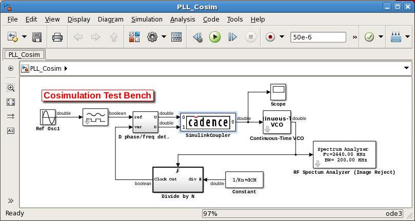
31 Verification of Circuit Design: Cosimulation Verify implementation against executable specifications SPECIFICATION DESIGN Algorithms Digital Analog Fixed-Point Physical IMPLEMENTATION VHDL, Verilog Spice-like TEST & VERIFICATION FPGA ASIC ASIC SMPS INTEGRATION 31
32 Verification of Circuit Design: Cosimulation Current Source Level Shifters Inverters Charge Loop Filter Discharge +/- 5 V supply + ground 24 nmos & pmos transistors 8 current sources for bias Input: 1V step functions from PFD Output: VCO control voltage 32
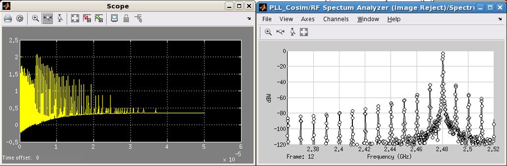
33 Cosimulation with Simulink Verify transistor level design: within the context of a full system simulation using visualization and analysis capabilities of Simulink and MATLAB testing each module independently of other modules 33
34 Cosimulation Verification Workflow Ideal behavioral model Cosimulation Refined model 34
35 Option 2: Code Generation 35


36 Mixed-Signal Design Gap How to Bridge Simulink and Mixed-Signal EDA Flows?? No standard API for analog simulators Different analog simulators provide different results Cosimulation can be slow Analog synthesis is still a research topic 36

37 Using C Code Generation and DPI-C Interface 1. Make your Simulink model C code generation compliant 2. Generate C code from your Simulink model 3. Automatically wrap the C code using SystemVerilog DPI-C interface 4. Import, build and simulate the equivalent behavioral SystemVerilog model in your IC design tool 2. SystemVerilog wrapper 1. C Code 3. IC Design Tool 37

38 Benefits of C Code Generation and DPI-C Export Fast simulation using the native SystemVerilog API IC design tool independent Customizable approach supported by MathWorks Leverages mature C code generation technology Most suitable for testbench generation and IC verification Support discrete and continuous time signals Simulink IC Design Tool 38
39 Some Details 39
40 Mixed-Signal PLL Model Charge Pump + Loop filter (analog) Binary Signal Source Phase / Frequency Detector (digital) Divider (triggered block) VCO (analog) 40

41 Export of Mixed-Signal Models Continuous time signals Discrete time solver 41


42 From Variable to Fixed Time Step Solver Chose a fixed sample time that it is small enough to give correct results Tradeoff accuracy and simulation time Large time step Small time step 42

43 Schedule the Execution of SystemVerilog Modules Simulink handles multi-rate systems automatically You need to define a scheduler to control the SystemVerilog execution Slow Clock 43


44 SystemVerilog Discretizes Time Discrete sample times in Simulink are integer multiple of an arbitrary fundamental sample time In SystemVerilog all sample times are integer multiple of 1fs (or a reference discrete sample time) 44
45 Certified by STARC 45
 Three Days Several semiconductor companies adopting STARC recommendation Japan member companies Non-member AMER/EMEA semiconductor majors")
46 STARC: Semiconductor Technology Academic Research Center Members: Fujitsu Semiconductor, Renesas, ROHM, Sony, Toshiba Key Takeaways Reference Motif Circuit (Sigma-Delta Converter) Circuit Level Two Months Verilog-AMS Six Days STARCAD-AMS (MathWorks) Three Days Several semiconductor companies adopting STARC recommendation Japan member companies Non-member AMER/EMEA semiconductor majors 46
47 Two Options for Integration with EDA tools Cosimulation Code generation Debugging Testbench generation Validation of behavioral models Regression testing 47
48 Mixed-Signal Verification: Reuse System Level Testbenches in IC Design Tools Two complementary verification approaches using Simulink system-level testbenches You don t have to become a modeling guru Cosimulation Find errors early and optimize your design Code generation The verification effort will be limited 48
49 Next Steps 49

50 Explore Mixed-Signal Design with MATLAB and Simulink 50


51 Browse Videos, Webinars, Articles 51


52 Download and Try Mixed-Signal Library Direct Link: 52
53 Request Onsite Meeting and Discussion Discuss your project and workflow with MathWorks Applications Engineering Team Digital: HDL code generation, verification Connectivity to Mentor, Cadence, and Synopsys flows Analog: Verilog-A or SystemVerilog code generation C code with DPI-C wrappers Connectivity to Cadence and Synopsys flows IBIS-AMI component creation from MATLAB and Simulink 53
54 Modeling and Verifying Mixed-Signal Designs with MATLAB and Simulink Rapid design construction SPECIFICATION Easier analog modeling ANALOG & DIGITAL DESIGN Multi-domain simulation IMPLEMENTATION IMPLEMENTATION TEST & VERIFICATION Integrated specification VHDL, Verilog Spice-like Rapid design iterations PROTOTYPE / INTEGRATION Improved team communication 54
Connecting MATLAB & Simulink with your SystemVerilog Workflow for Functional Verification
 Connecting MATLAB & Simulink with your SystemVerilog Workflow for Functional Verification Corey Mathis Industry Marketing Manager Communications, Electronics, and Semiconductors MathWorks 2014 MathWorks,
Design and Verify Embedded Signal Processing Systems Using MATLAB and Simulink
 Design and Verify Embedded Signal Processing Systems Using MATLAB and Simulink Giorgia Zucchelli, Application Engineer, MathWorks 17 January 2011, Technical University Eindhoven 1 Agenda Introduction to
Design and Verify Embedded Signal Processing Systems Using MATLAB and Simulink
 Design and Verify Embedded Signal Processing Systems Using MATLAB and Simulink Giorgia Zucchelli, Application Engineer, MathWorks 10 January 2013, Technical University Eindhoven 2013 The MathWorks, Inc.
Making the Most of your MATLAB Models to Improve Verification
 Making the Most of your MATLAB Models to Improve Verification Verification Futures 2016 Graham Reith Industry Manager: Communications, Electronics & Semiconductors Graham.Reith@mathworks.co.uk 2015 The
Accelerating FPGA/ASIC Design and Verification
 Accelerating FPGA/ASIC Design and Verification Tabrez Khan Senior Application Engineer Vidya Viswanathan Application Engineer 2015 The MathWorks, Inc. 1 Agenda Challeges with Traditional Implementation
Model-Based Design for Video/Image Processing Applications
 Model-Based Design for Video/Image Processing Applications The MathWorks Agenda Model-Based Design From MATLAB and Simulink to Altera FPGA Step-by-step design and implementation of edge detection algorithm
Hardware Implementation and Verification by Model-Based Design Workflow - Communication Models to FPGA-based Radio
 Hardware Implementation and Verification by -Based Design Workflow - Communication s to FPGA-based Radio Katsuhisa Shibata Industry Marketing MathWorks Japan 2015 The MathWorks, Inc. 1 Agenda Challenges
Design and Verification of FPGA and ASIC Applications Graham Reith MathWorks
 Design and Verification of FPGA and ASIC Applications Graham Reith MathWorks 2014 The MathWorks, Inc. 1 Agenda -Based Design for FPGA and ASIC Generating HDL Code from MATLAB and Simulink For prototyping
Design and Verification of FPGA Applications
 Design and Verification of FPGA Applications Giuseppe Ridinò Paola Vallauri MathWorks giuseppe.ridino@mathworks.it paola.vallauri@mathworks.it Torino, 19 Maggio 2016, INAF 2016 The MathWorks, Inc. 1 Agenda
Reducing the cost of FPGA/ASIC Verification with MATLAB and Simulink
 Reducing the cost of FPGA/ASIC Verification with MATLAB and Simulink Graham Reith Industry Manager Communications, Electronics and Semiconductors MathWorks Graham.Reith@mathworks.co.uk 2015 The MathWorks,
Reuse MATLAB Functions and Simulink Models in UVM Environments with Automatic SystemVerilog DPI Component Generation
 Reuse MATLAB Functions and Simulink Models in UVM Environments with Automatic SystemVerilog DPI Component Generation by Tao Jia, HDL Verifier Development Lead, and Jack Erickson, HDL Product Marketing
Modeling a 4G LTE System in MATLAB
 Modeling a 4G LTE System in MATLAB Part 3: Path to implementation (C and HDL) Houman Zarrinkoub PhD. Signal Processing Product Manager MathWorks houmanz@mathworks.com 2011 The MathWorks, Inc. 1 LTE Downlink
Model-Based Design for effective HW/SW Co-Design Alexander Schreiber Senior Application Engineer MathWorks, Germany
 Model-Based Design for effective HW/SW Co-Design Alexander Schreiber Senior Application Engineer MathWorks, Germany 2013 The MathWorks, Inc. 1 Agenda Model-Based Design of embedded Systems Software Implementation
Modelling and Simulation Made Easy with Simulink Tiffany Liang Application Engineer MathWorks
 Modelling and Simulation Made Easy with Simulink Tiffany Liang Application Engineer MathWorks 2015 The MathWorks, Inc. 1 What will you learn in this presentation? For those who are not familiar with Simulink
Hardware and Software Co-Design for Motor Control Applications
 Hardware and Software Co-Design for Motor Control Applications Jonas Rutström Application Engineering 2015 The MathWorks, Inc. 1 Masterclass vs. Presentation? 2 What s a SoC? 3 What s a SoC? When we refer
What's new in MATLAB and Simulink for Model-Based Design
 What's new in MATLAB and Simulink for Model-Based Design Magnus Jung Application Engineer 2016 The MathWorks, Inc. 1 What s New? 2 Model-Based Design Workflow RESEARCH REQUIREMENTS DESIGN Scheduling Event
Implementing MATLAB Algorithms in FPGAs and ASICs By Alexander Schreiber Senior Application Engineer MathWorks
 Implementing MATLAB Algorithms in FPGAs and ASICs By Alexander Schreiber Senior Application Engineer MathWorks 2014 The MathWorks, Inc. 1 Traditional Implementation Workflow: Challenges Algorithm Development
Abstract. Cycle Domain Simulator for Phase-Locked Loops
 Abstract Cycle Domain Simulator for Phase-Locked Loops Norman James October 1999 As computers become faster and more complex, clock synthesis becomes critical. Due to the relatively slower bus clocks compared
Intro to System Generator. Objectives. After completing this module, you will be able to:
 Intro to System Generator This material exempt per Department of Commerce license exception TSU Objectives After completing this module, you will be able to: Explain why there is a need for an integrated
Parameterize behavioral models using WiCkeD Modeling
 Parameterize behavioral models using WiCkeD Modeling Demonstrator: Charge Pump Phase Locked Loop (CP-PLL) Dr. Volker Glöckel Introduction Overview Motivation and Documented Use Cases Demonstrator: CP-PLL
Designing and Prototyping Digital Systems on SoC FPGA The MathWorks, Inc. 1
 Designing and Prototyping Digital Systems on SoC FPGA Hitu Sharma Application Engineer Vinod Thomas Sr. Training Engineer 2015 The MathWorks, Inc. 1 What is an SoC FPGA? A typical SoC consists of- A microcontroller,
A Beginner s Guide to SerDes and AMI Modeling. Todd Westerhoff, SiSoft Corey Mathis, MathWorks
 A Beginner s Guide to SerDes and AMI Modeling Todd Westerhoff, SiSoft Corey Mathis, MathWorks SPEAKERS Corey Mathis Industry Marketing Manager, MathWorks Corey.Mathis@mathworks.com, www.mathworks.com Corey
Four Best Practices for Prototyping MATLAB and Simulink Algorithms on FPGAs by Stephan van Beek, Sudhir Sharma, and Sudeepa Prakash, MathWorks
 Four Best Practices for Prototyping MATLAB and Simulink Algorithms on FPGAs by Stephan van Beek, Sudhir Sharma, and Sudeepa Prakash, MathWorks Chip design and verification engineers often write as many
AMS Behavioral Modeling
 CHAPTER 3 AMS Behavioral Modeling Ronald S. Vogelsong, Ph.D. Overview Analog designers have for many decades developed their design using a Bottom-Up design flow. First, they would gain the necessary understanding
Accelerate FPGA Prototyping with
 Accelerate FPGA Prototyping with MATLAB and Simulink September 21 st 2010 Stephan van Beek Senior Application Engineer 1 From Idea to Implementation DESIGN Algorithm Development MATLAB Simulink Stateflow
EEM870 Embedded System and Experiment Lecture 4: SoC Design Flow and Tools
 EEM870 Embedded System and Experiment Lecture 4: SoC Design Flow and Tools Wen-Yen Lin, Ph.D. Department of Electrical Engineering Chang Gung University Email: wylin@mail.cgu.edu.tw March 2013 Agenda Introduction
THE DESIGNER'S GUIDE TO VERILOG-AMS First Edition June 2004
 THE DESIGNER'S GUIDE TO VERILOG-AMS First Edition June 2004 KENNETH S. KUNDERT Cadence Design Systems OLAF ZINKE Cadence Design Systems k4 Kluwer Academic Publishers Boston/Dordrecht/London Chapter 1 Introduction
Hardware and Software Co-Design for Motor Control Applications
 Hardware and Software Co-Design for Motor Control Applications Gaurav Dubey Durvesh Kulkarni 2015 The MathWorks, Inc. 1 Key trend: Increasing demands from motor drives Advanced algorithms require faster
MODELING PHASE-LOCKED LOOPS USING VERILOG
 MODELING PHASE-LOCKED LOOPS USING VERILOG Jeffrey Meyer Director of Engineering Symmetricom, Inc. 3750 West Wind Blvd. Santa Rosa CA 95403, USA Abstract An essential component of any mixed signal embedded
Integrated Workflow to Implement Embedded Software and FPGA Designs on the Xilinx Zynq Platform Puneet Kumar Senior Team Lead - SPC
 Integrated Workflow to Implement Embedded Software and FPGA Designs on the Xilinx Zynq Platform Puneet Kumar Senior Team Lead - SPC 2012 The MathWorks, Inc. 1 Agenda Integrated Hardware / Software Top
Extending Digital Verification Techniques for Mixed-Signal SoCs with VCS AMS September 2014
 White Paper Extending Digital Verification Techniques for Mixed-Signal SoCs with VCS AMS September 2014 Author Helene Thibieroz Sr Staff Marketing Manager, Adiel Khan Sr Staff Engineer, Verification Group;
Extending Model-Based Design for HW/SW Design and Verification in MPSoCs Jim Tung MathWorks Fellow
 Extending Model-Based Design for HW/SW Design and Verification in MPSoCs Jim Tung MathWorks Fellow jim@mathworks.com 2014 The MathWorks, Inc. 1 Model-Based Design: From Concept to Production RESEARCH DESIGN
Harmony-AMS Analog/Mixed-Signal Simulator
 Harmony-AMS Analog/Mixed-Signal Simulator Yokohama, June 2004 Workshop 7/15/04 Challenges for a True Single-Kernel A/MS Simulator Accurate partition of analog and digital circuit blocks Simple communication
Model-Based Design: Generating Embedded Code for Prototyping or Production
 Model-Based Design: Generating Embedded Code for Prototyping or Production Ruth-Anne Marchant Application Engineer MathWorks 2016 The MathWorks, Inc. 1 2 ABB Accelerates Application Control Software Development
Parag Choudhary Engineering Architect
 Parag Choudhary Engineering Architect Agenda Overview of Design Trends & Designer Challenges PCB Virtual Prototyping in PSpice Simulator extensions for Models and Abstraction levels Examples of a coding
CO SIMULATION OF GENERIC POWER CONVERTER USING MATLAB/SIMULINK AND MODELSIM
 CO SIMULATION OF GENERIC POWER CONVERTER USING MATLAB/SIMULINK AND MODELSIM Ajay Singh MIT, Modinagar U.P (India) ABSTRACT In this paper we discuss about the co-simulation of generic converter using MATLAB
Moving MATLAB Algorithms into Complete Designs with Fixed-Point Simulation and Code Generation
 Moving MATLAB Algorithms into Complete Designs with Fixed-Point Simulation and Code Generation Houman Zarrinkoub, PhD. Product Manager Signal Processing Toolboxes The MathWorks Inc. 2007 The MathWorks,
Optimize DSP Designs and Code using Fixed-Point Designer
 Optimize DSP Designs and Code using Fixed-Point Designer MathWorks Korea 이웅재부장 Senior Application Engineer 2013 The MathWorks, Inc. 1 Agenda Fixed-point concepts Introducing Fixed-Point Designer Overview
This Part-B course discusses design techniques that are used to reduce noise problems in large-scale integration (LSI) devices.
 devices.") Course Introduction Purpose This Part-B course discusses design techniques that are used to reduce noise problems in large-scale integration (LSI) devices. Objectives Learn approaches and design methods
Course Introduction Purpose This Part-B course discusses design techniques that are used to reduce noise problems in large-scale integration (LSI) devices. Objectives Learn approaches and design methods
Model-Based Design for Altera FPGAs Using HDL Code Generation The MathWorks, Inc. 1
 Model-Based Design for Altera FPGAs Using HDL Code Generation Z 2011 The MathWorks, Inc. 1 Separate Views of DSP Implementation System Designer FPGA Designer Algorithm Design System Test Bench RTL Design
[Sub Track 1-3] FPGA/ASIC 을타겟으로한알고리즘의효율적인생성방법및신기능소개
![[Sub Track 1-3] FPGA/ASIC 을타겟으로한알고리즘의효율적인생성방법및신기능소개](/thumbs/82/85868302.jpg "[Sub Track 1-3] FPGA/ASIC 을타겟으로한알고리즘의효율적인생성방법및신기능소개") [Sub Track 1-3] FPGA/ASIC 을타겟으로한알고리즘의효율적인생성방법및신기능소개 정승혁과장 Senior Application Engineer MathWorks Korea 2015 The MathWorks, Inc. 1 Outline When FPGA, ASIC, or System-on-Chip (SoC) hardware is needed Hardware
[Sub Track 1-3] FPGA/ASIC 을타겟으로한알고리즘의효율적인생성방법및신기능소개 정승혁과장 Senior Application Engineer MathWorks Korea 2015 The MathWorks, Inc. 1 Outline When FPGA, ASIC, or System-on-Chip (SoC) hardware is needed Hardware
Lab. Course Goals. Topics. What is VLSI design? What is an integrated circuit? VLSI Design Cycle. VLSI Design Automation
 Course Goals Lab Understand key components in VLSI designs Become familiar with design tools (Cadence) Understand design flows Understand behavioral, structural, and physical specifications Be able to
IOT is IOMSLPT for Verification Engineers
 IOT is IOMSLPT for Verification Engineers Adam Sherer, Product Management Group Director TVS DVClub Bristol, Cambridge, Grenoble, and worldwide 12 September 2017 IOT = Internet of Mixed-Signal Low Power
101-1 Under-Graduate Project Digital IC Design Flow
 101-1 Under-Graduate Project Digital IC Design Flow Speaker: Ming-Chun Hsiao Adviser: Prof. An-Yeu Wu Date: 2012/9/25 ACCESS IC LAB Outline Introduction to Integrated Circuit IC Design Flow Verilog HDL
SEE Tolerant Self-Calibrating Simple Fractional-N PLL
 SEE Tolerant Self-Calibrating Simple Fractional-N PLL Robert L. Shuler, Avionic Systems Division, NASA Johnson Space Center, Houston, TX 77058 Li Chen, Department of Electrical Engineering, University
World Class Verilog & SystemVerilog Training
 World Class Verilog & SystemVerilog Training Sunburst Design - Expert Verilog-2001 FSM, Multi-Clock Design & Verification Techniques by Recognized Verilog & SystemVerilog Guru, Cliff Cummings of Sunburst
VCS AMS. Mixed-Signal Verification Solution. Overview. testing with transistor-level accuracy. Introduction. Performance. Multicore Technology
 DATASHEET VCS AMS Mixed-Signal Verification Solution Scalable mixedsignal regression testing with transistor-level accuracy Overview The complexity of mixed-signal system-on-chip (SoC) designs is rapidly
Targeting Motor Control Algorithms to System-on-Chip Devices
 Targeting Motor Control Algorithms to System-on-Chip Devices Dr.-Ing. Werner Bachhuber 2015 The MathWorks, Inc. 1 Why use Model-Based Design to develop motor control applications on SoCs? Enables early
Simulation, prototyping and verification of standards-based wireless communications
 Simulation, prototyping and verification of standards-based wireless communications Colin McGuire, Neil MacEwen 2015 The MathWorks, Inc. 1 Real Time LTE Cell Scanner with MATLAB and Simulink 2 Real time
A mm 2 780mW Fully Synthesizable PLL with a Current Output DAC and an Interpolative Phase-Coupled Oscillator using Edge Injection Technique
 A 0.0066mm 2 780mW Fully Synthesizable PLL with a Current Output DAC and an Interpolative Phase-Coupled Oscillator using Edge Injection Technique Wei Deng, Dongsheng Yang, Tomohiro Ueno, Teerachot Siriburanon,
Model-Based Design: Design with Simulation in Simulink
 Model-Based Design: Design with Simulation in Simulink Ruth-Anne Marchant Application Engineer MathWorks 2016 The MathWorks, Inc. 1 2 Outline Model-Based Design Overview Modelling and Design in Simulink
High Performance Mixed-Signal Solutions from Aeroflex
 High Performance Mixed-Signal Solutions from Aeroflex We Connect the REAL World to the Digital World Solution-Minded Performance-Driven Customer-Focused Aeroflex (NASDAQ:ARXX) Corporate Overview Diversified
ASIC world. Start Specification Design Verification Layout Validation Finish
 AMS Verification Agenda ASIC world ASIC Industrial Facts Why Verification? Verification Overview Functional Verification Formal Verification Analog Verification Mixed-Signal Verification DFT Verification
Designing and Analysing Power Electronics Systems Using Simscape and SimPowerSystems
 Designing and Analysing Power Electronics Systems Using Simscape and SimPowerSystems Gernot Schraberger Industry Manager, Europe Industrial Automation & Machinery, Energy Production MathWorks 2012 The
Chapter 1 Overview of Digital Systems Design
 Chapter 1 Overview of Digital Systems Design SKEE2263 Digital Systems Mun im/ismahani/izam {munim@utm.my,e-izam@utm.my,ismahani@fke.utm.my} February 8, 2017 Why Digital Design? Many times, microcontrollers
Verilog. What is Verilog? VHDL vs. Verilog. Hardware description language: Two major languages. Many EDA tools support HDL-based design
 Verilog What is Verilog? Hardware description language: Are used to describe digital system in text form Used for modeling, simulation, design Two major languages Verilog (IEEE 1364), latest version is
Introduction to C and HDL Code Generation from MATLAB
 Introduction to C and HDL Code Generation from MATLAB 이웅재차장 Senior Application Engineer 2012 The MathWorks, Inc. 1 Algorithm Development Process Requirements Research & Design Explore and discover Design
SoC Verification Methodology. Prof. Chien-Nan Liu TEL: ext:
 SoC Verification Methodology Prof. Chien-Nan Liu TEL: 03-4227151 ext:4534 Email: jimmy@ee.ncu.edu.tw 1 Outline l Verification Overview l Verification Strategies l Tools for Verification l SoC Verification
THE DESIGNER S GUIDE TO VERILOG-AMS
 THE DESIGNER S GUIDE TO VERILOG-AMS THE DESIGNER S GUIDE BOOK SERIES Consulting Editor Kenneth S. Kundert Books in the series: The Designer s Guide to Verilog-AMS ISBN: 1-00-80-1 The Designer s Guide to
EE 4755 Digital Design Using Hardware Description Languages
 EE 4755 Digital Design Using Hardware Description Languages Basic Information URL: http://www.ece.lsu.edu/v Offered by: David M. Koppelman, Room 345 ERAD Building 578-5482. koppel@ece.lsu.edu, http://www.ece.lsu.edu/koppel/koppel.html
Chapter 5: ASICs Vs. PLDs
 Chapter 5: ASICs Vs. PLDs 5.1 Introduction A general definition of the term Application Specific Integrated Circuit (ASIC) is virtually every type of chip that is designed to perform a dedicated task.
Cover TBD. intel Quartus prime Design software
 Cover TBD intel Quartus prime Design software Fastest Path to Your Design The Intel Quartus Prime software is revolutionary in performance and productivity for FPGA, CPLD, and SoC designs, providing a
Mixed Signal Verification Transistor to SoC
 Mixed Signal Verification Transistor to SoC Martin Vlach Chief Technologist AMS July 2014 Agenda AMS Verification Landscape Verification vs. Design Issues in AMS Verification Modeling Summary 2 AMS VERIFICATION
Motor Control: Model-Based Design from Concept to Implementation on heterogeneous SoC FPGAs Alexander Schreiber, MathWorks
 Motor Control: Model-Based Design from Concept to Implementation on heterogeneous SoC FPGAs Alexander Schreiber, MathWorks 2014 The MathWorks, Inc. 1 Some components of a production application Production
01 1 Electronic Design Automation (EDA) the correctness, testability, and compliance of a design is checked by software
 the correctness, testability, and compliance of a design is checked by software") 01 1 Electronic Design Automation (EDA) 01 1 Electronic Design Automation (EDA): (Short Definition) The use of software to automate electronic (digital and analog) design. Electronic Design Automation
01 1 Electronic Design Automation (EDA) 01 1 Electronic Design Automation (EDA): (Short Definition) The use of software to automate electronic (digital and analog) design. Electronic Design Automation
Cover TBD. intel Quartus prime Design software
 Cover TBD intel Quartus prime Design software Fastest Path to Your Design The Intel Quartus Prime software is revolutionary in performance and productivity for FPGA, CPLD, and SoC designs, providing a
Digital System Design with SystemVerilog
 Digital System Design with SystemVerilog Mark Zwolinski AAddison-Wesley Upper Saddle River, NJ Boston Indianapolis San Francisco New York Toronto Montreal London Munich Paris Madrid Capetown Sydney Tokyo
Introduction to Control Systems Design
 Experiment One Introduction to Control Systems Design Control Systems Laboratory Dr. Zaer Abo Hammour Dr. Zaer Abo Hammour Control Systems Laboratory 1.1 Control System Design The design of control systems
Contents 1 Introduction 2 Functional Verification: Challenges and Solutions 3 SystemVerilog Paradigm 4 UVM (Universal Verification Methodology)
") 1 Introduction............................................... 1 1.1 Functional Design Verification: Current State of Affair......... 2 1.2 Where Are the Bugs?.................................... 3 2 Functional
1 Introduction............................................... 1 1.1 Functional Design Verification: Current State of Affair......... 2 1.2 Where Are the Bugs?.................................... 3 2 Functional
Schematic/Design Creation
 Schematic/Design Creation D A T A S H E E T MAJOR BENEFITS: Xpedition xdx Designer is a complete solution for design creation, definition, and reuse. Overview Creating competitive products is about more
Mixed-signal Modeling Using Simulink based-c
 Mixed-signal Modeling Using Simulink based-c Shoufeng Mu, Michael Laisne 1 Agenda Objectives of Mixed-signal (MS) modeling Advantages of Simulink based MS modeling Simulink based MS modeling flow 1) Build
Digital System Design Lecture 2: Design. Amir Masoud Gharehbaghi
 Digital System Design Lecture 2: Design Amir Masoud Gharehbaghi amgh@mehr.sharif.edu Table of Contents Design Methodologies Overview of IC Design Flow Hardware Description Languages Brief History of HDLs
Hardware-Software Co-Design and Prototyping on SoC FPGAs Puneet Kumar Prateek Sikka Application Engineering Team
 Hardware-Software Co-Design and Prototyping on SoC FPGAs Puneet Kumar Prateek Sikka Application Engineering Team 2015 The MathWorks, Inc. 1 Agenda Integrated Hardware / Software Top down Workflow for SoC
Introducing Simulink R2012b for Signal Processing & Communications Graham Reith Senior Team Leader, UK Application Engineering
 Introducing Simulink R2012b for Signal Processing & Communications Graham Reith Senior Team Leader, UK Application Engineering 2012 The MathWorks, Inc. 1 Simulink R2012b the most significant upgrade to
SmartSpice Verilog-A Interface. Behavioral and Structural Modeling Tool - Device Model Development
 SmartSpice Verilog-A Interface Behavioral and Structural Modeling Tool - Device Model Development Verilog-A Models and Features Agenda Overview Design Capability Compact Modeling Verilog-A Inteface - 2
FPGA Design Challenge :Techkriti 14 Digital Design using Verilog Part 1
 FPGA Design Challenge :Techkriti 14 Digital Design using Verilog Part 1 Anurag Dwivedi Digital Design : Bottom Up Approach Basic Block - Gates Digital Design : Bottom Up Approach Gates -> Flip Flops Digital
2015 The MathWorks, Inc. 1
 2015 The MathWorks, Inc. 1 신호처리응용을위한 Model Based Design Workflow 이웅재부장 2015 The MathWorks, Inc. 2 CASE: Software in Signal Processing Application (Medical) Medical devices are increasingly driven by complex
Mentor Graphics Solutions Enable Fast, Efficient Designs for Altera s FPGAs. Fall 2004
 Mentor Graphics Solutions Enable Fast, Efficient Designs for Altera s FPGAs Fall 2004 Agenda FPGA design challenges Mentor Graphics comprehensive FPGA design solutions Unique tools address the full range
01-1 Electronic Design Automation (EDA) The use of software to automate electronic (digital and analog) design.
 The use of software to automate electronic (digital and analog) design.") 01-1 Electronic Design Automation (EDA) 01-1 Electronic Design Automation (EDA): (Short Definition) The use of software to automate electronic (digital and analog) design. Electronic Design Automation
01-1 Electronic Design Automation (EDA) 01-1 Electronic Design Automation (EDA): (Short Definition) The use of software to automate electronic (digital and analog) design. Electronic Design Automation
MATLAB/Simulink in der Mechatronik So einfach geht s!
 MATLAB/Simulink in der Mechatronik So einfach geht s! Executable s with Simulation Models Continuous Test and Verification Automatic Generation Tobias Kuschmider Applikationsingenieur 2014 The MathWorks,
DSP Flow for SmartFusion2 and IGLOO2 Devices - Libero SoC v11.6 TU0312 Quickstart and Design Tutorial
 DSP Flow for SmartFusion2 and IGLOO2 Devices - Libero SoC v11.6 TU0312 Quickstart and Design Tutorial Table of Contents Introduction... 3 Tutorial Requirements... 3 Synphony Model Compiler ME (Microsemi
Hardware and Software Co-Design for Motor Control Applications
 Hardware and Software Co-Design for Motor Control Applications GianCarlo Pacitti Senior Application Engineer, MathWorks 2015 The MathWorks, Inc. 1 Agenda Why use Hardware and Software for motor control?
Model-Based Embedded System Design
 Model-Based Embedded System Design Pieter J. Mosterman Senior Research Scientist The MathW orks, Inc. 2007 The MathWorks, Inc. Agenda Introduction Embedded Systems Design Demo A Design Activity Dynamic
Mixed-Signal. From ICs to Systems. Mixed-Signal solutions from Aeroflex Colorado Springs. Standard products. Custom ASICs. Mixed-Signal modules
 A passion for performance. Mixed-Signal solutions from Aeroflex Colorado Springs Standard products Custom ASICs Mixed-Signal modules Circuit card assemblies Mixed-Signal From ICs to Systems RadHard ASICs
EE 4755 Digital Design Using Hardware Description Languages
 EE 4755 Digital Design Using Hardware Description Languages Basic Information URL: http://www.ece.lsu.edu/v Offered by: David M. Koppelman, Room 3316R P. F. Taylor Hall 578-5482. koppel@ece.lsu.edu, http://www.ece.lsu.edu/koppel/koppel.html
Evolution of CAD Tools & Verilog HDL Definition
 Evolution of CAD Tools & Verilog HDL Definition K.Sivasankaran Assistant Professor (Senior) VLSI Division School of Electronics Engineering VIT University Outline Evolution of CAD Different CAD Tools for
FPGA PROTOTYPING BY VERILOG EXAMPLES XILINX SPARTAN 3 VERSION
 page 1 / 5 page 2 / 5 fpga prototyping by verilog pdf A field-programmable gate array (FPGA) is an integrated circuit designed to be configured by a customer or a designer after manufacturing hence the
TEXAS INSTRUMENTS ANALOG UNIVERSITY PROGRAM DESIGN CONTEST MIXED SIGNAL TEST INTERFACE CHRISTOPHER EDMONDS, DANIEL KEESE, RICHARD PRZYBYLA SCHOOL OF
 TEXASINSTRUMENTSANALOGUNIVERSITYPROGRAMDESIGNCONTEST MIXED SIGNALTESTINTERFACE CHRISTOPHEREDMONDS,DANIELKEESE,RICHARDPRZYBYLA SCHOOLOFELECTRICALENGINEERINGANDCOMPUTERSCIENCE OREGONSTATEUNIVERSITY I. PROJECT
THE DESIGN ENVIRONMENT FOR HETEROGENEOUS SYSTEMS
 THE DESIGN ENVIRONMENT FOR HETEROGENEOUS SYSTEMS SystemC / SystemC AMS based Simulation and Modeling Technologies Outline COSIDE Today COSIDE 2.0 COSIDE Future 2 Management Summary Combination of analog
Case study of Mixed Signal Design Flow
 IOSR Journal of VLSI and Signal Processing (IOSR-JVSP) Volume 6, Issue 3, Ver. II (May. -Jun. 2016), PP 49-53 e-issn: 2319 4200, p-issn No. : 2319 4197 www.iosrjournals.org Case study of Mixed Signal Design
The Application of SystemC to the Design and Implementation of a High Data Rate Satellite Transceiver
 The Application of SystemC to the Design and Implementation of a High Data Rate Satellite Transceiver The MITRE Corporation Approved for public release. Distribution unlimited. Case #07-0782 Contract No.
Lecture 1: Introduction Course arrangements Recap of basic digital design concepts EDA tool demonstration
 TKT-1426 Digital design for FPGA, 6cp Fall 2011 http://www.tkt.cs.tut.fi/kurssit/1426/ Tampere University of Technology Department of Computer Systems Waqar Hussain Lecture Contents Lecture 1: Introduction
Real-Time Testing in a Modern, Agile Development Workflow
 Real-Time Testing in a Modern, Agile Development Workflow Simon Eriksson Application Engineer 2015 The MathWorks, Inc. 1 Demo Going from Desktop Testing to Real-Time Testing 2 Key Take-Aways From This
MATLAB/Simulink 기반의프로그래머블 SoC 설계및검증
 MATLAB/Simulink 기반의프로그래머블 SoC 설계및검증 이웅재부장 Application Engineering Group 2014 The MathWorks, Inc. 1 Agenda Introduction ZYNQ Design Process Model-Based Design Workflow Prototyping and Verification Processor
Programmable Logic Devices HDL-Based Design Flows CMPE 415
 HDL-Based Design Flows: ASIC Toward the end of the 80s, it became difficult to use schematic-based ASIC flows to deal with the size and complexity of >5K or more gates. HDLs were introduced to deal with
New paradigm for MEMS+IC Co-development
 New paradigm for MEMS+IC Co-development MEMS 진보된스마트세상을만듭니다. Worldwide First MEMS+IC Co-development Solution New paradigm for MEMS+IC Co-development A New Paradigm for MEMS+IC Development MEMS design
AMS DESIGN METHODOLOGY
 OVER VIEW CADENCE ANALOG/ MIXED-SIGNAL DESIGN METHODOLOGY The Cadence Analog/Mixed-Signal (AMS) Design Methodology employs advanced Cadence Virtuoso custom design technologies and leverages silicon-accurate
ASYNC Rik van de Wiel COO Handshake Solutions
 ASYNC 2006 Rik van de Wiel COO Handshake Solutions Outline Introduction to Handshake Solutions Applications Design Tools ARM996HS Academic Program Handshake Solutions Started as research project in Philips
Ein Modell - viele Zielsysteme
 Ein Modell - viele Zielsysteme Automatische Codegenerierung aus MATLAB und Simulink Dr.-Ing. Daniel Weida 2015 The MathWorks, Inc. 1 Industry trends Code generation is expanding rapidly C C++ VHDL Verilog
Top-Down Design of Mixed-Signal Circuits
 Top-Down Design of Mixed-Signal Circuits Ken Kundert Cadence Design Systems San Jose, California, USA Abstract With mixed-signal designs becoming more complex and time-to-market windows shrinking, designers