William J. Donnelly III, PhD. Jon A. Herlocker, PhD. - Sr. Optical Engineer. - Sr. Optical Scientist
|
|
|
- Ferdinand Rolf Pierce
- 6 years ago
- Views:
Transcription


1 Applications of Non-sequential Ray Tracing to Investigate Lenslet Image Point Spread Function Uniformity Under Geometrical & Physical Optical Coherent & Incoherent Source Modeling William J. Donnelly III, PhD - Sr. Optical Engineer Jon A. Herlocker, PhD - Sr. Optical Scientist
2 Overview Past work using Shack-Hartmann Wavefront Sensors (SHWS) to quantify intraocular scatter Wavefront & scatter simulation through a Shack-Hartmann (S/H) lenslet array Techniques for identifying scatter sources Visual comparison to real S/H imaging
3 Introduction Aberrations, diffraction, & scatter in the eye decrease retinal image quality Although used mainly for aberrations, SHWS contain all this information Previous work: Optimizing SHWS for sensing scatter Univ. of Houston Col. Of Optometry (UHCO) Wavefront Sciences, Inc.

4 Background Using the SHWS to assess forward scatter

5 S/H derived forward scatter is correlated to vision by optics reversibility Vision with forward scatter from nuclear cataract SHWS to assess forward light scatter SHWS Guide star PSF from SHWS probe beam Forward Forward Forward scatter from the lens is correlated
6 What can be done w/ scatter information from a SH image? Clinical assessment of intraocular scatter associated w/ wavefront data Create improved visual performance predictions & PSF reconstruction Assist development of IOLs, spectacles, lenses, & ocular instrumentation to reduce stray light Predict refractive surgery outcomes, i.e. halos scatter from trauma or disease
7 SHWS has 2 primary optical channels 1) Wavefront channel 2) Forward scatter channel

8 SHWS layout: 2 channels
9 Previous UHCO TINCO study showed that w/ advancing nuclear cataract there was Transmission loss in the wavefront channel Lenslet image PSFs were attenuated in the CCD plane (conjugate to the retina) PSF height had best correlation w/ nuclear cataract We learned to assess cataract progression, we must optimize & fix exposure Veiling luminance in the forward scatter channel local areas at the CCD plane Could contain both forward scatter & backscatter from surfaces Mild correlation w/ nuclear cataract using 2 nd moment techniques
 Age 25, NO = 0.")

10 Height fields from 2 patient SH images (lenslet image PSFs) Age 25, NO = 0.8 Clear Eye (PSFs are pointy and steep) Age 71, NO = 5.6 Dense Nuclear Cataract (PSFs attenuate, veiling luminance increases)
11 2 types of intraocular scatter Volumetric (bulk) scatter Attenuates retinal & lenslet image PSFs Caused by small particles in the lens volume Increases w/ age & nuclear cataract Can be characterized by Rayleigh & Mie scatter models Surface scatter Creates areas of localized veiling luminance Increases w/ lens & corneal surface roughness Probe beam & tear film surface can contribute Refractive surgery or IOLs can contribute Characterized by Harvey scatter models
12 We can predict PSF attenuation from Mie volumetric scatter via microspheres in solution & computer modeling. TINCO linked Mie scatter to nuclear opalescence. Clear Dense cataract Physical model: Cox et al 2001 Computer Model & confirmed physical model: Donnelly, et al 2005
13 Harvey surface scatter Harvey scatter can be predicted using the Bi-Directional Scatter Distribution Function (BSDF) The Bi-Directional Reflectance Distribution (BRDF) & Bi- Directional Transmittance Distribution (BTDF) are derived from the BSDF
14 Harvey surface scatter model BSDF as a function of angle
15 Volumetric (bulk) & Surface scatter Harvey Mie Harvey
16 General Research Question Can we separate & quantify aberrations and volumetric and surface scatter in a Shack- Hartmann image?
17 Specific Research Question What uniformity exists in lenslet image PSFs when we use nonsequential ray tracing to model Lenslet arrays & Sources Incoherent & coherent Wavefront propagation Volumetric & surface scatter
18 Methods We used the Advanced Systems & Analysis Program (ASAP) by Breault Research Organization Time tested optical systems engineering & analysis program In use & continuous development since 1978 Visually compare results w/ TINCO data
19 Methods The end system of a SHWS was modeled Used a coherent source to illustrate diffraction patterns & cross-talk Produced lenslet image PSFs at the detector w/ and w/out aberrations Used incoherent volumetric & surface scatter
20 Lenslet array modeling Pillow lenslet array


21 Typical pillow rectangular lenslet array
22 To illustrate lenslet PSFs in detail We will look at smaller 4x4 section of a larger 30x30 lenslet array

23 Section of lenslet array 4x4 Detector


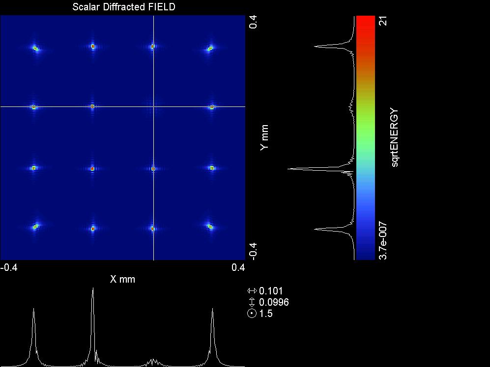
24 4x4 rectangular array: Lenslet image PSFs No aberrations Notice diffraction pattern


25 4x4 rectangular array: Lenslet image PSFs Aberrations: 3um defocus & 2um sphere Notice PSF blur & displacement
26 Aberrations (only) modeling shows Aberrations cause some lenslet image PSF displacement & blur Next step: Add scattering
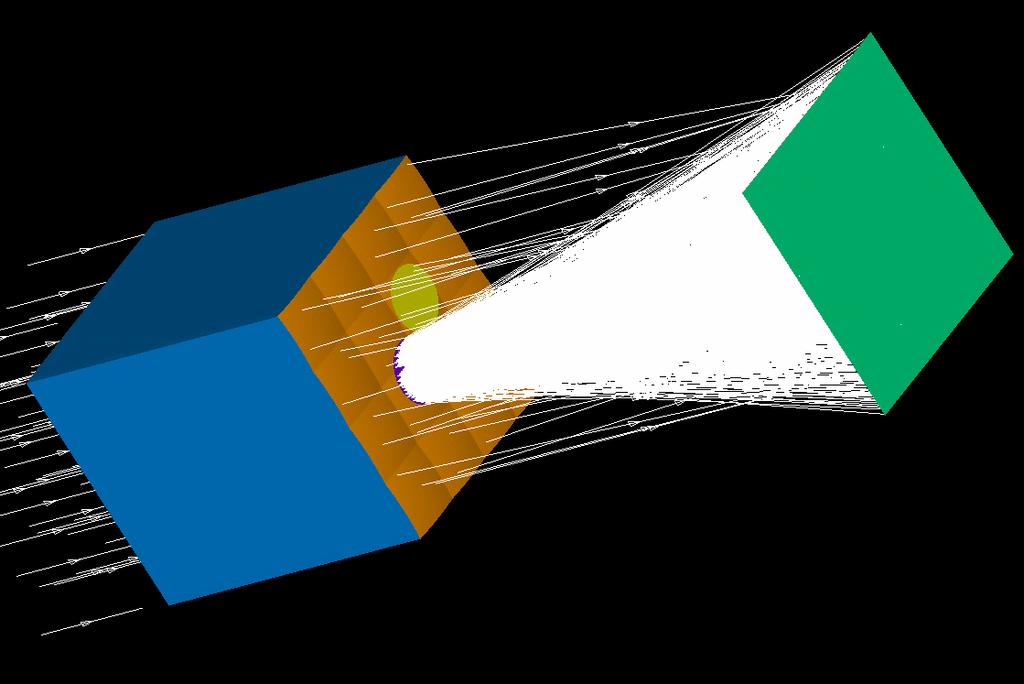
27 Attenuation from scatter From TINCO we learned volumetric scatter from nuclear cataract or blockage (such as floaters or cortical cataract) can cause transmission loss (attenuation) over local lenslet image PSFs So, let s insert a local attenuator in the wavefront

28 Local attenuator from nuclear cataract volumetric scatter or blockage Detector Lenslet array
29
30
31 Profile trace through the 2 nd row Attenuated lenslet image PSF
32 And now for surface scatter.. Insert a localized Harvey model in the forward scatter channel Surface scatter is conjugate to the lenslet array, not the CCD
33 Volume scatterer Surface scatterer
34
35 Log scaling Log scaling can enhance observable scatter in a SH image Next slides show & surface scatter combined in log scale
36 Crosshairs on Attenuated PSF.

37 Crosshairs on Surface scatter

38 Crosshairs on Surface scatter. Clamping shows angular extent of scattering.


39 SH images & scatter maps of real eyes
40 Results We have demonstrated methods to model aberrations & scatter separately & simultaneously Modeling shows similarities to real S/H images inclusive of scatter With scatter model parameters derived from the image, we could reverse calculate the extent of local volumetric & surface scattering in the eye
41 Conclusions With wavefront & quantifiable scatter data We can develop a more complete description of the retinal image We can also use this data to develop custom eye models Such as aberrant or diseased eyes To assist intraocular, spectacle, & contact lens design Estimate refractive surgery outcomes To provide a modular Interface w/ ocular instrumentation designs For What if? scenarios for vision research
42 At Breault Research, we are incorporating these techniques into advanced eye models inclusive of intraocular scatter Advanced Human Eye Model (AHEM)

43 Refraction & scatter through spectacles & into eyes
44 Thank you for your attention William J. Donnelly III, PhD
Methods for Measuring Ocular Wavefront Error
 8 th Wavefront Congress, Santa Fe, Feb. 2007 Methods for Measuring Ocular Wavefront Error Larry N. Thibos School of Optometry, Indiana University Vision Research at http://www.opt.indiana.edu Aberrometry
Optometer. Subjective Assessment of Refractive Error. Myopia. Far Point. Myopia. Far Point
 Optometer Subjective Assessment of Refractive rror Far Point Myopia Far Point Myopia 1 Subjective Assessment of Refractive rror Power φ = 1 / f Far Point Myopia f - Δz d z Subjective Assessment of Refractive
Extracting Wavefront Error From Shack-Hartmann Images Using Spatial Demodulation
 Etracting Wavefront Error From Shack-Hartmann Images Using Spatial Demodulation Edwin J. Sarver, PhD; Jim Schwiegerling, PhD; Raymond A. Applegate, OD, PhD ABSTRACT PURPOSE: To determine whether the spatial
Scattering measurements. Guidelines for measurements service
 Scattering measurements Guidelines for measurements service 1 Content Introduction Light Tec Presentation Instruments availalable. Scattering measurements Refelctors Diffusers Colors issuses Volume Scattering
Optical Scattering. Analysis. Measurement and SPIE PRESS. John C. Stover THIRD EDITION. Bellingham, Washington USA
 Optical Scattering Measurement and Analysis THIRD EDITION John C. Stover SPIE PRESS Bellingham, Washington USA Contents Preface to the First Edition xiii Preface to the Second Edition xv Acknowledgments
WHITE PAPER. Application of Imaging Sphere for BSDF Measurements of Arbitrary Materials
 Application of Imaging Sphere for BSDF Measurements of Arbitrary Materials Application of Imaging Sphere for BSDF Measurements of Arbitrary Materials Abstract BSDF measurements are broadly applicable to
Basic optics. Geometrical optics and images Interference Diffraction Diffraction integral. we use simple models that say a lot! more rigorous approach
 Basic optics Geometrical optics and images Interference Diffraction Diffraction integral we use simple models that say a lot! more rigorous approach Basic optics Geometrical optics and images Interference
Optical Design with Zemax for PhD
 Optical Design with Zemax for PhD Lecture : Physical Optics 06-03-3 Herbert Gross Winter term 05 www.iap.uni-jena.de Preliminary Schedule No Date Subject Detailed content.. Introduction 0.. Basic Zemax
Preparatory School to the Winter College on Optics in Imaging Science January Selected Topics of Fourier Optics Tutorial
 2222-11 Preparatory School to the Winter College on Optics in Imaging Science 24-28 January 2011 Selected Topics of Fourier Optics Tutorial William T. Rhodes Florida Atlantic University Boca Raton USA
Improving visual function diagnostic metrics. Charles Campbell
 Improving visual function diagnostic metrics Charles Campbell Metrics - What are they? What are they used for? A metric assigns a numerical value or a set of values to characterize some chosen phenomenon
How to Use the Luminit LSD Scatter Model
 How to Use the Luminit LSD Scatter Model Summary: This article describes the characteristics and use of Luminit s LSD scatter model in OpticStudio. The scatter model presented here is the idealized scatter
How to Refine Your Refractive Error Post-Phaco with Premium IOL s. Astigmatism & Multifocal IOL s. Coma & Multifocal IOL OPERATIVE
 How to Refine Your Refractive Error Post-Phaco with Premium IOL s Mounir Khalifa, MD, PhD Prof of Ophthalmology, Tanta University President of Egyptian Refractive Club Chairman of Horus Vision Correction
Light Tec Scattering measurements guideline
 Light Tec Scattering measurements guideline 1 Our Laboratory Light Tec is equipped with a Photometric Laboratory (a dark room) including: Goniophotometers: REFLET180s. High specular bench (10 meters),
Lasers PH 645/ OSE 645/ EE 613 Summer 2010 Section 1: T/Th 2:45-4:45 PM Engineering Building 240
 Lasers PH 645/ OSE 645/ EE 613 Summer 2010 Section 1: T/Th 2:45-4:45 PM Engineering Building 240 John D. Williams, Ph.D. Department of Electrical and Computer Engineering 406 Optics Building - UAHuntsville,
Chapter 26 Geometrical Optics
 Chapter 26 Geometrical Optics 1 Overview of Chapter 26 The Reflection of Light Forming Images with a Plane Mirror Spherical Mirrors Ray Tracing and the Mirror Equation The Refraction of Light Ray Tracing
Wavefront (Center) 502. EMPOWER YOUR PRACTICE WITH comprehensive complete anterior segment analysis
 502. EMPOWER YOUR PRACTICE WITH comprehensive complete anterior segment analysis") Wavefront 584 547 494 493 (Center) 502 496 507 520 529 559 EMPOWER YOUR PRACTICE WITH comprehensive complete anterior segment analysis Narrow Angles Cataracts Glaucoma Risk THE POWER OF THREE The VX130
Wavefront 584 547 494 493 (Center) 502 496 507 520 529 559 EMPOWER YOUR PRACTICE WITH comprehensive complete anterior segment analysis Narrow Angles Cataracts Glaucoma Risk THE POWER OF THREE The VX130
Light Tec Scattering measurements guideline
 Light Tec Scattering measurements guideline 1 Our Laboratory Light Tec is equipped with a Photometric Laboratory (a dark room) including: Goniophotometers: REFLET 180S. High specular bench (10 meters),
OPTI-521 Graduate Report 2 Matthew Risi Tutorial: Introduction to imaging, and estimate of image quality degradation from optical surfaces
 OPTI-521 Graduate Report 2 Matthew Risi Tutorial: Introduction to imaging, and estimate of image quality degradation from optical surfaces Abstract The purpose of this tutorial is to introduce the concept
Chapter 36. Image Formation
 Chapter 36 Image Formation Apr 22, 2012 Light from distant things We learn about a distant thing from the light it generates or redirects. The lenses in our eyes create images of objects our brains can
Winter College on Optics in Environmental Science February Adaptive Optics: Introduction, and Wavefront Correction
 2018-23 Winter College on Optics in Environmental Science 2-18 February 2009 Adaptive Optics: Introduction, and Wavefront Correction Love G. University of Durham U.K. Adaptive Optics: Gordon D. Love Durham
A software simmulation of Hartmann-Schack patterns for real corneas
 A software simmulation of Hartmann-Schack patterns for real corneas L. A. Carvalho*, Jarbas C. Castro*, P. Schor, W. Chamon *Instituto de Física de São Carlos (IFSC - USP), Brazil lavcf@ifsc.sc.usp.br
34.2: Two Types of Image
 Chapter 34 Images 34.2: Two Types of Image For you to see an object, your eye intercepts some of the light rays spreading from the object and then redirect them onto the retina at the rear of the eye.
Ray Optics. Physics 11. Sources of Light Rays: Self-Luminous Objects. The Ray Model of Light
 Physics 11 Ray Optics Ray Model of Light Reflection Plane Mirrors Spherical Mirrors Ray Tracing Images from a Concave Mirror Images from a Convex Mirror Slide 18-3 The Ray Model of Light Sources of Light
Light Tec Scattering measurements guideline
 Light Tec Scattering measurements guideline 1 2 Light Tec Locations REFLET assembling plant, Aix-en-Provence, France Light Tec GmbH, Munich, Germany German office Light Tec Sarl, Hyères, France Main office
Light Tec Scattering measurements guideline
 Light Tec Scattering measurements guideline 1 Our Laboratory Light Tec is equipped with a Photometric Laboratory (a dark room) including: Goniophotometers: REFLET 180S. High specular bench (10 meters),
(A) Electromagnetic. B) Mechanical. (C) Longitudinal. (D) None of these.
 Electromagnetic. B) Mechanical. (C) Longitudinal. (D) None of these.") Downloaded from LIGHT 1.Light is a form of radiation. (A) Electromagnetic. B) Mechanical. (C) Longitudinal. 2.The wavelength of visible light is in the range: (A) 4 10-7 m to 8 10-7 m. (B) 4 10 7
Downloaded from LIGHT 1.Light is a form of radiation. (A) Electromagnetic. B) Mechanical. (C) Longitudinal. 2.The wavelength of visible light is in the range: (A) 4 10-7 m to 8 10-7 m. (B) 4 10 7
Chapter 35 &36 Physical Optics
 Chapter 35 &36 Physical Optics Physical Optics Phase Difference & Coherence Thin Film Interference 2-Slit Interference Single Slit Interference Diffraction Patterns Diffraction Grating Diffraction & Resolution
Nicholas J. Giordano. Chapter 24. Geometrical Optics. Marilyn Akins, PhD Broome Community College
 Nicholas J. Giordano www.cengage.com/physics/giordano Chapter 24 Geometrical Optics Marilyn Akins, PhD Broome Community College Optics The study of light is called optics Some highlights in the history
Light. Electromagnetic wave with wave-like nature Refraction Interference Diffraction
 Light Electromagnetic wave with wave-like nature Refraction Interference Diffraction Light Electromagnetic wave with wave-like nature Refraction Interference Diffraction Photons with particle-like nature
Medical Photonics Lecture Optical Engineering
 Medical Photonics Lecture Optical Engineering Lecture 13: Metrology 2018-02-01 Herbert Gross Winter term 2017 www.iap.uni-jena.de 2 Schedule Optical Engineering 2017 No Subject Ref Date Detailed Content
(Goal 3) (Goal 3) (Goals 4 and 5) (Goals 4 and 5)
 (Goal 3) (Goals 4 and 5) (Goals 4 and 5)") 10 This thesis addresses the measurement of geometrical properties (surface geometry, tilt and decentration) of the crystalline lens in normal eyes, and their changes with accommodation. In addition, it
10 This thesis addresses the measurement of geometrical properties (surface geometry, tilt and decentration) of the crystalline lens in normal eyes, and their changes with accommodation. In addition, it
Modeling Custom Surface Roughness with LucidShape 2D Scatter Curve BSDF Material
 WHITE PAPER Modeling Custom Surface Roughness with LucidShape 2D Scatter Curve BSDF Material Author Andreas Bielawny, Ph.D. CAE Synopsys, Inc. Abstract LucidShape accurately simulates how light interacts
Lecture Outline Chapter 26. Physics, 4 th Edition James S. Walker. Copyright 2010 Pearson Education, Inc.
 Lecture Outline Chapter 26 Physics, 4 th Edition James S. Walker Chapter 26 Geometrical Optics Units of Chapter 26 The Reflection of Light Forming Images with a Plane Mirror Spherical Mirrors Ray Tracing
Lens Design. Craig Olson. Julie Bentley. Field Guide to. John E. Greivenkamp, Series Editor SPIE. SPIE Field Guides. Volume FG27
 Field Guide to Lens Design Julie Bentley Craig Olson SPIE Field Guides Volume FG27 John E. Greivenkamp, Series Editor SPIE PRESS Bellingham,Washington USA vii Glossary of Symbols and Acronyms xi Fundamentals
This Excel spreadsheet has been developed as a companion tool for the JCRS guest editorial:
 Page 1 of 6 Overview: This Excel spreadsheet has been developed as a companion tool for the JCRS guest editorial: Abulafia A, Koch DD, Holladay JT, Wang L, Hill WE. Pursuing perfection in intraocular lens
3. Image formation, Fourier analysis and CTF theory. Paula da Fonseca
 3. Image formation, Fourier analysis and CTF theory Paula da Fonseca EM course 2017 - Agenda - Overview of: Introduction to Fourier analysis o o o o Sine waves Fourier transform (simple examples of 1D
(Refer Slide Time: 00:11)
") Fundamentals of optical and scanning electron microscopy Dr S Sankaran Department of Metallurgical and Materials Engineering Indian Institute of Technology, Madras Module 01 Unit-1 Fundamentals of optics
Fundamentals of optical and scanning electron microscopy Dr S Sankaran Department of Metallurgical and Materials Engineering Indian Institute of Technology, Madras Module 01 Unit-1 Fundamentals of optics
The Lens. Refraction and The Lens. Figure 1a:
 Lenses are used in many different optical devices. They are found in telescopes, binoculars, cameras, camcorders and eyeglasses. Even your eye contains a lens that helps you see objects at different distances.
Virtual and Mixed Reality > Near-Eye Displays. Simulation of Waveguide System containing a Complex 2D Exit Pupil Expansion
 Virtual and Mixed Reality > Near-Eye Displays Simulation of Waveguide System containing a Complex 2D Exit Pupil Expansion Task/System Illustration? intensity at output of waveguide eye model? intensity
Imaging Sphere Measurement of Luminous Intensity, View Angle, and Scatter Distribution Functions
 Imaging Sphere Measurement of Luminous Intensity, View Angle, and Scatter Distribution Functions Hubert Kostal, Vice President of Sales and Marketing Radiant Imaging, Inc. 22908 NE Alder Crest Drive, Suite
Wavefront Diagnostic. One-Touch COMPREHENSIVE VISUAL ASSESSMENT IN UNDER 90 SECONDS.
 Wavefront Diagnostic One-Touch COMPREHENSIVE VISUAL ASSESSMENT IN UNDER 90 SECONDS. VX120 A GAME CHANGING WAVEFRONT DIAGNOSTIC DEVICE FOR COMPREHENSIVE VISUAL ASSESSMENT REFRACTION AND VISUAL PERFORMANCE
Measure at the speed of light...
 Measure at the speed of light... LENSTAR LS 900 Biometry Explore new dimensions... Complete optical biometer including CCT and lens thickness Align once, get all results fast biometrical assessment Non
Building the Future of Optical Modeling and Design
 SIOM, Lecture Series Building the Future of Optical Modeling and Design Frank Wyrowski Friedrich-Schiller-University, Professor LightTrans GmbH, President Jena, Germany frank.wyrowski@uni-jena.de Lecture
Diffraction. Single-slit diffraction. Diffraction by a circular aperture. Chapter 38. In the forward direction, the intensity is maximal.
 Diffraction Chapter 38 Huygens construction may be used to find the wave observed on the downstream side of an aperture of any shape. Diffraction The interference pattern encodes the shape as a Fourier
f. (5.3.1) So, the higher frequency means the lower wavelength. Visible part of light spectrum covers the range of wavelengths from
 So, the higher frequency means the lower wavelength. Visible part of light spectrum covers the range of wavelengths from") Lecture 5-3 Interference and Diffraction of EM Waves During our previous lectures we have been talking about electromagnetic (EM) waves. As we know, harmonic waves of any type represent periodic process
Lecture 5-3 Interference and Diffraction of EM Waves During our previous lectures we have been talking about electromagnetic (EM) waves. As we know, harmonic waves of any type represent periodic process
Light: Geometric Optics (Chapter 23)
") Light: Geometric Optics (Chapter 23) Units of Chapter 23 The Ray Model of Light Reflection; Image Formed by a Plane Mirror Formation of Images by Spherical Index of Refraction Refraction: Snell s Law 1
Light: Geometric Optics (Chapter 23) Units of Chapter 23 The Ray Model of Light Reflection; Image Formed by a Plane Mirror Formation of Images by Spherical Index of Refraction Refraction: Snell s Law 1
Chapter 3. Physical phenomena: plane parallel plate. This chapter provides an explanation about how rays of light physically behave when
 Chapter 3 Physical phenomena: plane parallel plate This chapter provides an explanation about how rays of light physically behave when propagating through different medium (different index of refraction).
City Research Online. Permanent City Research Online URL:
 Gruppetta, S, Koechlin, L, Lacombe, F & Puget, P (0015). Curvature sensor for the measurement of the static corneal topography and the dynamic tear film topography in the human eye.. Opt Lett, 30(20),
Children fitted with contact lenses following cataract surgery
 Information for Patients Manchester Royal Eye Hospital Optometry Department Children fitted with contact lenses following cataract surgery What is a cataract? The eye works a bit like a camera; it contains
Chapter 23. Geometrical Optics (lecture 1: mirrors) Dr. Armen Kocharian
 Dr. Armen Kocharian") Chapter 23 Geometrical Optics (lecture 1: mirrors) Dr. Armen Kocharian Reflection and Refraction at a Plane Surface The light radiate from a point object in all directions The light reflected from a plane
Chapter 23 Geometrical Optics (lecture 1: mirrors) Dr. Armen Kocharian Reflection and Refraction at a Plane Surface The light radiate from a point object in all directions The light reflected from a plane
Aberrations in Holography
 Aberrations in Holography D Padiyar, J Padiyar 1070 Commerce St suite A, San Marcos, CA 92078 dinesh@triple-take.com joy@triple-take.com Abstract. The Seidel aberrations are described as they apply to
FRED Display Application Note
 FRED Display Application Note Most displays consist of several optical components. The most important component is the source of light that illuminates the display. All displays need a mechanism to send
OPTI 513R / Optical Testing
 OPTI 513R / Optical Testing Instructor: Dae Wook Kim Meinel Building Rm 633, University of Arizona, Tucson, AZ 85721 E-Mail: dkim@optics.arizona.edu Website: sites.google.com/site/opti513r/ Office Hours:
EELE 482 Lab #3. Lab #3. Diffraction. 1. Pre-Lab Activity Introduction Diffraction Grating Measure the Width of Your Hair 5
 Lab #3 Diffraction Contents: 1. Pre-Lab Activit 2 2. Introduction 2 3. Diffraction Grating 4 4. Measure the Width of Your Hair 5 5. Focusing with a lens 6 6. Fresnel Lens 7 Diffraction Page 1 (last changed
PHY 171 Lecture 6 (January 18, 2012)
") PHY 171 Lecture 6 (January 18, 2012) Light Throughout most of the next 2 weeks, we will be concerned with the wave properties of light, and phenomena based on them (interference & diffraction). Light also
PHY 171 Lecture 6 (January 18, 2012) Light Throughout most of the next 2 weeks, we will be concerned with the wave properties of light, and phenomena based on them (interference & diffraction). Light also
Light: Geometric Optics
 Light: Geometric Optics 23.1 The Ray Model of Light Light very often travels in straight lines. We represent light using rays, which are straight lines emanating from an object. This is an idealization,
3B SCIENTIFIC PHYSICS
 3B SCIENTIFIC PHYSICS Instruction sheet 06/18 ALF Laser Optics Demonstration Set Laser Optics Supplement Set Page 1 2 3 3 3 4 4 4 5 5 5 6 6 6 7 7 7 8 8 8 9 9 9 10 10 10 11 11 11 12 12 12 13 13 13 14 14
EO-1 Stray Light Analysis Report No. 3
 EO-1 Stray Light Analysis Report No. 3 Submitted to: MIT Lincoln Laboratory 244 Wood Street Lexington, MA 02173 P.O. # AX-114413 May 4, 1998 Prepared by: Lambda Research Corporation 80 Taylor Street P.O.
Polarized Downwelling Radiance Distribution Camera System
 Polarized Downwelling Radiance Distribution Camera System Kenneth J. Voss Physics Department, University of Miami Coral Gables, Fl. 33124 phone: (305) 284-2323 ext 2 fax: (305) 284-4222 email: voss@physics.miami.edu
Algebra Based Physics
 Slide 1 / 66 Slide 2 / 66 Algebra Based Physics Geometric Optics 2015-12-01 www.njctl.org Table of ontents Slide 3 / 66 lick on the topic to go to that section Reflection Spherical Mirror Refraction and
The CAFADIS camera: a new tomographic wavefront sensor for Adaptive Optics.
 1st AO4ELT conference, 05011 (2010) DOI:10.1051/ao4elt/201005011 Owned by the authors, published by EDP Sciences, 2010 The CAFADIS camera: a new tomographic wavefront sensor for Adaptive Optics. J.M. Rodríguez-Ramos
Metrology and Sensing
 Metrology and Sensing Lecture 4: Fringe projection 2016-11-08 Herbert Gross Winter term 2016 www.iap.uni-jena.de 2 Preliminary Schedule No Date Subject Detailed Content 1 18.10. Introduction Introduction,
Contact Lens Op-cal Design Op-miza-on U-lizing a Binocular Vision Model. Ben Wooley Johnson & Johnson Vision Care, Inc.
 Lens Op-cal Op-miza-on U-lizing a Binocular Vision Model Ben Wooley Johnson & Johnson Vision Care, Inc. March 4, 2016 Outline Full Eye and Vision Model > Predicts binocular vision for given viewing distance
Baseline Shack Hartmann Design for the 6.5m MMT f/9 Focus
 Baseline Shack Hartmann Design for the 6.5m MMT f/9 Focus S. C. West (swest@as.arizona.edu) and H. Olson 1 Multiple Mirror Telescope Observatory, Tucson, AZ MMTO Technical Memo #01-01, September 2001 http://nemo.as.arizona.edu/~swest/pdfs/sh_wfs_tb.pdf
INTRODUCTION REFLECTION AND REFRACTION AT BOUNDARIES. Introduction. Reflection and refraction at boundaries. Reflection at a single surface
 Chapter 8 GEOMETRICAL OPTICS Introduction Reflection and refraction at boundaries. Reflection at a single surface Refraction at a single boundary Dispersion Summary INTRODUCTION It has been shown that
Development of Digital Visualization Tool: Visual Image Simulation (VIS) DigitEyez / Brandon Zimmerman
 DigitEyez / Brandon Zimmerman") Development of Digital Visualization Tool: Visual Image Simulation (VIS) DigitEyez / Brandon Zimmerman This has been approved by our customer (12/14/17) Project Coordinator: Ali Hashim Customer Liaison:
Development of Digital Visualization Tool: Visual Image Simulation (VIS) DigitEyez / Brandon Zimmerman This has been approved by our customer (12/14/17) Project Coordinator: Ali Hashim Customer Liaison:
The I Kone Lens. Boston XO. Valley CONTAX. Springfield, OR. Manufactured in
 The I Kone Lens Manufactured in Boston XO Valley CONTAX Springfield, OR Contact Lens Fitting Goals for Keratoconus Vision Comfort Corneal Health Fit / Centration Happy Patient Selecting the Best Contact
Ray Optics Demonstration Set (RODS) and Ray Optics Demonstration Set Plus (RODS+) USER S GUIDE
 and Ray Optics Demonstration Set Plus (RODS+) USER S GUIDE") Ray Optics Demonstration Set (RODS) and Ray Optics Demonstration Set Plus USER S GUIDE 1 NO. OF EXP. Table of contents TITLE OF EXPERIMENT SET TO USE Introduction Tables of the set elements E1 Reflection
Ray Optics Demonstration Set (RODS) and Ray Optics Demonstration Set Plus USER S GUIDE 1 NO. OF EXP. Table of contents TITLE OF EXPERIMENT SET TO USE Introduction Tables of the set elements E1 Reflection
Lens Design I. Lecture 11: Imaging Herbert Gross. Summer term
 Lens Design I Lecture 11: Imaging 2015-06-29 Herbert Gross Summer term 2015 www.iap.uni-jena.de 2 Preliminary Schedule 1 13.04. Basics 2 20.04. Properties of optical systrems I 3 27.05. 4 04.05. Properties
MEASUREMENT OF SMALL TRANSVERSE BEAM SIZE USING INTERFEROMETRY
 MEASUREMENT OF SMALL TRANSVERSE BEAM SIZE USING INTERFEROMETRY T. Mitsuhashi High Energy Accelerator Research Organisation, Oho, Tsukuba, Ibaraki, 35-81 Japan Abstract The principle of measurement of the
Metrology and Sensing
 Metrology and Sensing Lecture 4: Fringe projection 2018-11-09 Herbert Gross Winter term 2018 www.iap.uni-jena.de 2 Schedule Optical Metrology and Sensing 2018 No Date Subject Detailed Content 1 16.10.
Chapter 23. Light Geometric Optics
 Chapter 23. Light Geometric Optics There are 3 basic ways to gather light and focus it to make an image. Pinhole - Simple geometry Mirror - Reflection Lens - Refraction Pinhole Camera Image Formation (the
Chapter 18 Ray Optics
 Chapter 18 Ray Optics Chapter Goal: To understand and apply the ray model of light. Slide 18-1 Chapter 18 Preview Looking Ahead Text p. 565 Slide 18-2 Wavefronts and Rays When visible light or other electromagnetic
Wavefronts and Rays. When light or other electromagnetic waves interact with systems much larger than the wavelength, it s a good approximation to
 Chapter 33: Optics Wavefronts and Rays When light or other electromagnetic waves interact with systems much larger than the wavelength, it s a good approximation to Neglect the wave nature of light. Consider
Phys 102 Lecture 17 Introduction to ray optics
 Phys 102 Lecture 17 Introduction to ray optics 1 Physics 102 lectures on light Light as a wave Lecture 15 EM waves Lecture 16 Polarization Lecture 22 & 23 Interference & diffraction Light as a ray Lecture
Lecture PowerPoint. Chapter 25 Physics: Principles with Applications, 6 th edition Giancoli
 Lecture PowerPoint Chapter 25 Physics: Principles with Applications, 6 th edition Giancoli 2005 Pearson Prentice Hall This work is protected by United States copyright laws and is provided solely for the
Physical or wave optics
 Physical or wave optics In the last chapter, we have been studying geometric optics u light moves in straight lines u can summarize everything by indicating direction of light using a ray u light behaves
AP Physics: Curved Mirrors and Lenses
 The Ray Model of Light Light often travels in straight lines. We represent light using rays, which are straight lines emanating from an object. This is an idealization, but is very useful for geometric
Geometrical Optics INTRODUCTION. Wave Fronts and Rays
 Geometrical Optics INTRODUCTION In this experiment, the optical characteristics of mirrors, lenses, and prisms will be studied based on using the following physics definitions and relationships plus simple
Name: Chapter 14 Light. Class: Date: 143 minutes. Time: 143 marks. Marks: Comments: Page 1 of 53
 Chapter 4 Light Name: Class: Date: Time: 43 minutes Marks: 43 marks Comments: Page of 53 A person can see an image of himself in a tall plane mirror. The diagram shows how the person can see his hat. (a)
Medical Photonics Lecture Optical Engineering
 Medical Photonics Lecture Optical Engineering Lecture 13: Metrology 2018-02-01 Herbert Gross Winter term 2017 www.iap.uni-jena.de 2 Photometric Properties Relations of the 4 main definitions Cassarly's
IOVS - IOVS R2. Total corneal power estimation: Ray tracing method vs. Gaussian optics formula
 IOVS - IOVS-0-.R Total corneal power estimation: Ray tracing method vs. Gaussian optics formula Journal: Investigative Ophthalmology & Visual Science Manuscript ID: IOVS-0-.R Manuscript Type: Article Date
Final Exam. Today s Review of Optics Polarization Reflection and transmission Linear and circular polarization Stokes parameters/jones calculus
 Physics 42200 Waves & Oscillations Lecture 40 Review Spring 206 Semester Matthew Jones Final Exam Date:Tuesday, May 3 th Time:7:00 to 9:00 pm Room: Phys 2 You can bring one double-sided pages of notes/formulas.
Chapter 34: Geometrical Optics
 Chapter 34: Geometrical Optics Mirrors Plane Spherical (convex or concave) Lenses The lens equation Lensmaker s equation Combination of lenses E! Phys Phys 2435: 22: Chap. 34, 3, Pg Mirrors New Topic Phys
2/26/2016. Chapter 23 Ray Optics. Chapter 23 Preview. Chapter 23 Preview
 Chapter 23 Ray Optics Chapter Goal: To understand and apply the ray model of light. Slide 23-2 Chapter 23 Preview Slide 23-3 Chapter 23 Preview Slide 23-4 1 Chapter 23 Preview Slide 23-5 Chapter 23 Preview
Slide 1. Slide 2. Slide 3 3 CATEGORIES. 4 th CATEGORY Depth-of-Focus. Depth-of-Focus Lenses. Historically Intraocular Lenses
 Slide 1 Depth-of-Focus Lenses Slide 2 Historically Intraocular Lenses 3 CATEGORIES Traditional Monofocal Monofocal Toric Multi-focal 4 th CATEGORY Depth-of-Focus Slide 3 Monofocal and Monofocal Toric lenses
Waves & Oscillations
 Physics 42200 Waves & Oscillations Lecture 40 Review Spring 2016 Semester Matthew Jones Final Exam Date:Tuesday, May 3 th Time:7:00 to 9:00 pm Room: Phys 112 You can bring one double-sided pages of notes/formulas.
Refraction. P04 Refraction (complete).notebook. November 06, What is a medium? Ex.
.notebook. November 06, What is a medium? Ex.") http://www.youtube.com/watch?v=fd1544bm_c4&playnext=1&list=pla6430972cd25464c&feature=results_video http://www.youtube.com/watch?v=fhbz40jio4q Refraction What is a medium? Ex. Refraction refers to the
http://www.youtube.com/watch?v=fd1544bm_c4&playnext=1&list=pla6430972cd25464c&feature=results_video http://www.youtube.com/watch?v=fhbz40jio4q Refraction What is a medium? Ex. Refraction refers to the
Lit Appearance Modeling of Illumination Systems
 Lit Appearance Modeling of Illumination Systems R. John Koshel* Breault Research Organization, Inc. Copyright 2002 Society of Photo-Optical Instrumentation Engineers. This paper will be published in the
New Features in CODE V Version 10
 Webinar Series New Features in CODE V Version 10 3280 East Foothill Boulevard Pasadena, California 91107 USA (626) 795-9101 Fax (626) 795-0184 e-mail: service@opticalres.com World Wide Web: http://www.opticalres.com
LIGHT. Descartes particle theory, however, could not be used to explain diffraction of light.
 1 LIGHT Theories of Light In the 17 th century Descartes, a French scientist, formulated two opposing theories to explain the nature of light. These two theories are the particle theory and the wave theory.
History of Light. 5 th Century B.C.
 History of Light 5 th Century B.C. Philosophers thought light was made up of streamers emitted by the eye making contact with an object Others thought that light was made of particles that traveled from
New Scatterometer for Spatial Distribution Measurements of Light Scattering from Materials
 10.2478/v10048-012-0012-y MEASUREMENT SCIENCE REVIEW, Volume 12, No. 2, 2012 New Scatterometer for Spatial Distribution Measurements of Light Scattering from Materials 1,3 E. Kawate, 1,2 M. Hain 1 AIST,
ISO INTERNATIONAL STANDARD. Particle size analysis Laser diffraction methods Part 1: General principles
 INTERNATIONAL STANDARD ISO 13320-1 First edition 1999-11-01 Particle size analysis Laser diffraction methods Part 1: General principles Analyse granulométrique Méthodes par diffraction laser Partie 1:
At the interface between two materials, where light can be reflected or refracted. Within a material, where the light can be scattered or absorbed.
 At the interface between two materials, where light can be reflected or refracted. Within a material, where the light can be scattered or absorbed. The eye sees by focusing a diverging bundle of rays from
18.4 Release Notes May 10th, 2018
 18.4 Release Notes May 10 th, 2018 CONTENTS 1 Sequential Features... 3 1.1 Full-Field Aberration analysis (Professional and Premium editions)... 3 1.2 GRIN surface usage with User-Defined and Grid Sag
CHAPTER 26 INTERFERENCE AND DIFFRACTION
 CHAPTER 26 INTERFERENCE AND DIFFRACTION INTERFERENCE CONSTRUCTIVE DESTRUCTIVE YOUNG S EXPERIMENT THIN FILMS NEWTON S RINGS DIFFRACTION SINGLE SLIT MULTIPLE SLITS RESOLVING POWER 1 IN PHASE 180 0 OUT OF
ISO INTERNATIONAL STANDARD. Particle size analysis Laser diffraction methods. Analyse granulométrique Méthodes par diffraction laser
 INTERNATIONAL STANDARD ISO 13320 First edition 2009-10-01 Corrected version 2009-12-01 Particle size analysis Laser diffraction methods Analyse granulométrique Méthodes par diffraction laser Reference
Metrology and Sensing
 Metrology and Sensing Lecture 11: Measurement of basic system properties 017-01-03 Herbert Gross Winter term 016 www.iap.uni-jena.de Preliminary Schedule No Date Subject Detailed Content 1 18.10. Introduction
Feature Map. Work the way you want, faster, easier... with the same Zemax reliability. RIBBONS / EDITORS
 Feature Map Feature Map Work the way you want, faster, easier... with the same Zemax reliability. Zemax brings a new level of productivity to optics simulation software with OpticStudio14. Built on Zemax