Light Tec Scattering measurements guideline
|
|
|
- Norman Mason
- 5 years ago
- Views:
Transcription

1 Light Tec Scattering measurements guideline 1
, Video photometer Lux meter Luminancemeter, Spectrophotometer, Integrating spheres: 6 (in gold for infrared), 8 & 40 inch. The dark room is new and well equipped.")
2 Our Laboratory Light Tec is equipped with a Photometric Laboratory (a dark room) including: Goniophotometers: REFLET180s. High specular bench (10 meters), Video photometer Lux meter Luminancemeter, Spectrophotometer, Integrating spheres: 6 (in gold for infrared), 8 & 40 inch. The dark room is new and well equipped. Light Tec moved to his new office in In the laboratory, the temperature is controlled and regulated for optimal measurement environment. Laboratory class:
3 Our Products: Summary Instruments Mini-Diff REFLET 180S High Specular Type BRDF/BTDF BRDF/BTDF BRDF Dynamic range Wavelength range 622nm, 850nm, 940nm 400nm to 1700nm 280nm to 10,6µm Incident angles Fixed: 0, 20, 40, 60 Tunable: +90 to -90 Tunable: +90 to 0 Angular range Sphere [0 ; 75 ] [0 ; 360 ] Full sphere 1 Plan from -10 to +90 Angular accuracy < 2 < 0.1 < 0.02 Repeatability < 5% < 1% <1% Weight 2kg 80kg 200Kg Advantages Plug & Play Easy to use & Fast Portable & Compact Attractive cost High dynamic range Very high dynamic range Measurement at 0,02 from the specular High precision High repeatability Customisable wavelength range


4 Scattering measurement: scanning planes BRDF Scanning in one plane: 2D BRDF BTDF Scanning in one plane: 2D BTDF Scanning in several planes, by 10 steps: 3D BRDF Scanning in several planes, by 10 steps: 3D BTDF 10 step 10 step 4

5 AOI recommendations Minimum Incident angles: For BRDF (reflection), when the goniometer is rotating, the detector can obstruct the incident lighting beam. We do have a 4 dead zone because of this: No light coming back on the normal surface for AOI 0. There is not enough distributed light and results are not accurate for AOI < 10. Therefore, we do recommend AOI > 10. Maximum Incident angles: Because of cosine consideration, a beam of 3 mm at the level of the sample surface becomes an ellipse. The spot sized collected by the receiver has to be smaller than 12 mm at the level of the sample. For this reason we limit the maximum incident angle to 85. In case measurements will be implemented into an optical simulation software, the BSDF characterization is done for incident angles close to the real case. By default we do recommend to measure BSDF for 10, 30, 50, clogged AOI max 85 5


6 AOI examples Example 1: For a louver, most of the rays have incident angles of 0 to 60 on the reflector. Example 2: For an automotive speedometer needle, most of the TIR incident angles are between 30 and 90. 6
.")
7 Colour and filtered BSDF measurements The BRDF values delivered are the TOTAL BRDF INTEGRATED over one wavelength range. Filter use: we can use different filters as photopic filters, RGB filters or many optical filters (from 300nm to 1700nm each 50nm). Photopic filter RGB filters Using these filters, we are able to provide a filtered BSDF. 7


8 Spectral BSDF The scattering distribution can change versus the colour (wavelength): applications such as paints, phosphors, lipsticks etc. In that case we use a different detector a spectroradiometer. It measures BRDF or BTDF from 380nm to 760nm. The result is one BSDF distribution each 0,6nm, 1nm, 5nm or 10nm in the wavelength range. This is a large amount of data that has to be handled in an optical simulation software! We are able to measure 2D or 3D spectral BSDF completely. However, we do recommend 2D, which is already quite complex. 8
9 BSDF delivery 2D BRDF: in the incident plane, BRDF value each 0.1, for each incident angle. 2D BTDF: in the incident plane, BTDF value each 0.1, for each incident angle. 3D BRDF: 18 different planes every 10, BRDF value each 0.1, for each incident angle. 3D BTDF: 18 different planes every 10, BTDF value each 0.1, for each incident angle. Files delivered o Standard: text file (not scripted) o On Demand: LightTools format, ASTM format, Support to generate other format Abg, Gaussian/Lambertian Support to import in other software (ASAP, FRED, TRACEPRO, SPEOS, ZEMAX) 9
10 Anisotropy and Isotropy Isotropy This is the most general case. The sample scatters the light uniformly regardless of the light in an angle of incidence. Anisotropy The scattering distribution depends on plane of the incident light. Generally, those samples appear to have stripes on their surfaces. In this case, we can rotate the incident plane by 90. In many cases two 3D BRDF measurements are enough: Y Y Z Z X X One 3D BRDF for an incident plane parallel to the micro lines One 3D BRDF for an incident plane perpendicular to the micro lines 10

 can be tuned from 1mm to 12mm.")
11 Recommendations Flatness of the sample : The sample has to be flat. Otherwise, a divergent beam is generated at the same time by the scattering and the curvature. Scattering only Curved, reflecting and scattering Curved and reflecting only Beam size: The beam diameter (spot size on the sample) can be tuned from 1mm to 12mm. In the case of measuring a hammer surface, the period of the hammer structure should not exceed a value of 3mm. 11


12 Case of reflectors : Diffused reflector and Near Specular (NS) reflector If the diffused beam is > 20, we measure one 3D BRDF in each incident plane every 10. If the diffused beam is between 5 and 20, we do two bundles of measurements: One measurement 3D BRDF with plane every 10, One measurement near specular with plane every 1 Measurement that we call Near Specular have a diffused beam of < 5. We scan around the specular beam with a step of 1 between each slice. Step 1 The Near Specular measurement is done with High Specular Bench. If the divergence of the diffused beam is smaller than 5, please see the slide explaining the method of High Specular Measurement. 12


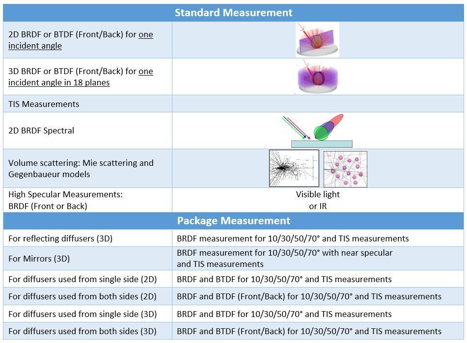
13 Case of transmissive diffusers Cases Measurements Transmissive Diffusers used in transmission only Transmissive Diffusers used in transmission and reflection from one side Transmissive Diffusers used in transmission and reflection used from both sides Guided diffuser (TIR) Volume diffusers BTDF BRDF &BTDF : Front or Back BRDF &BTDF : Front and Back TIR BRDF (optional TIR BTDF) Volume diffusers: MIE scattering & Gegenbaueur 13
, then there are 2 cases: The light hits the polished")


, the software will propagate the light")
14 Case of diffusers: Definition Back & Front, BRDF & BTDF If BRDF and BTDF is used and the diffuser is only on one side, (the other side is polished), then there are 2 cases: The light hits the polished surface = FRONT first The light hits the diffused surface = BACK first In case the measurement has to be used into an optical simulation software, the surface property has to be applied on the surface (left or right one), BUT The diffuser HAS to be set up with a refractive index of 1 as the ambient air. If the refractive index is not 1 (e.g. 1.5 as the refractive index of the plastic material for example), the software will propagate the light in the diffuser and will apply Fresnel reflection on the diffused light resulting in additional scattering that isnot currently existing. FRONT BACK n WRONG n CORRECT 14
15 Transmissive Diffuser BRDF - BTDF Reflector BRDF Diagram to help you to choose your measurements Isotropic 2D Identical surfaces Measurement on 1 side: Front Anisotropic 3D with plan every 10 Near specular Non Identical surfaces Measurement on both side: Front: polished/rough Back: rough/polished 3D with plan every 1 15
 has no influence is required.")

16 Total Internal Reflectance (TIR) light measurements In this case our focus is in the light diffused inside the light pipe. A special measurement where the top surface (Fresnel losses) has no influence is required. The way to do this is to get the light injected with an hemispherical lens (24mm diameter) towards the surface diffusing back the light. The light is then measured as a normal BRDF or BTDF. The best sample to measure is a sample where the hemisphere has exactly the same index as the sample. So ideally we want to get an hemisphere with the diffuser on the plane surface. If this special hemisphere cannot be supplied, we use one of our hemisphere (PC) with an index matching liquid between the hemisphere and the sample. 16


17 Total Integrated Scattered light measurements (TIS) Definition of TIS: it is the ratio of the total power generated by all contributions of scattered radiation into the forward or the backward half-space or both to the power of the incident radiation IT IS NOT POSSIBLE TO GET THE TIS FROM A BSDF MEASUREMENT ONLY! 1. A goniophotometer scans a limited number of planes, so it does not collect all the scattered light. 2. In the case of a scatter distribution with a peak around the specular direction, the sensor may not have the right dynamic to measure the exact maximum values. By a given BSDF measurement (BRDF or BTDF), we can calculate the TIS with an accuracy: Around few % for one diffused sample, Around 5 % to.100 % for one specular sample, Due to such enormous potential errors, we do recommend a high accurate TIS measurement using an integrating sphere. 17
 during the manufacturing cycle.")


18 Total Integrated Scattered light measurements (TIS) For space programs for example, it is important to evaluate the evolution of the TIS (Total Integrated Scatter light) during the manufacturing cycle. Different parameters can affect the actual TIS of the surface. Measuring bundle of samples following different treatments can help a lot on the knowledge of the most efficient technique: - Aging - Cleaning - Manufacturing These TIS measurement can be done with - White light (from 400 to 1700nm), - With laser emitting at 532, 638, 808 and 850nm - With IR laser at 1,55, 3,39 and 10,6µm, - Repeatability +/- 0.03% 3 different integrating spheres are available for samples from 10 to 100mm. Example of several measured AOI Acktar type materials 18

19 Volume Scattering measurement For volume scattering, we first measure the 2D BTDF of the same sample in 4 different thicknesses. Using these 4 BTDF measurements, we have developed a special routine allowing to find the parameter needed to simulate this material with: Mie Scattering model: radius, density and refractive index of particles. Gegenbaueur model: mean free path, Alpha and g parameters. Afterwards we double check if the calculated data provide the same simulation results as the measurements. 19


20 Volume Scattering: examples Picture of a measured sample Grey colour < Flash Spectral colour \/ Headlights 20


21 High Resolution BRDF We can measure as close as 0.02 from the specular: 2D BRDF, very high dynamic: 10 13, Laser sources at 280, 375, 445, 532, 638 and 850nm and IR lasers at 1,55, 3,39 and 10,6µm. Laser signatures Instrument: bench of 10 meters long. Application : high polished mirror, quasi specular and a lot more. De-convolution of the measurement 21


 or structure Mirrors Baffle")
22 High Resolution BRDF examples For some space programs for example, it is important to measure the Scattering data of material: with a very narrow diffusion for mirrors for baffles (edge scattering) or structure Mirrors Baffle Structure 22
23 Measurement prices 23
24 CONTACT Light Tec SARL Pôle d Activités Hyérois, 1128 Route de Toulon Hyères France Phone: For more information, please contact us! Fax: E mail: sales@lighttec.fr Website: 24
Light Tec Scattering measurements guideline
 Light Tec Scattering measurements guideline 1 Our Laboratory Light Tec is equipped with a Photometric Laboratory (a dark room) including: Goniophotometers: REFLET 180S. High specular bench (10 meters),
Light Tec Scattering measurements guideline
 Light Tec Scattering measurements guideline 1 2 Light Tec Locations REFLET assembling plant, Aix-en-Provence, France Light Tec GmbH, Munich, Germany German office Light Tec Sarl, Hyères, France Main office
Light Tec Scattering measurements guideline
 Light Tec Scattering measurements guideline 1 Our Laboratory Light Tec is equipped with a Photometric Laboratory (a dark room) including: Goniophotometers: REFLET 180S. High specular bench (10 meters),
Scattering measurements. Guidelines for measurements service
 Scattering measurements Guidelines for measurements service 1 Content Introduction Light Tec Presentation Instruments availalable. Scattering measurements Refelctors Diffusers Colors issuses Volume Scattering
Light Tec. Characterization of ultra-polished surfaces in UV and IR. ICSO October 2016 Biarritz, France
 ICSO 2016 17-21 October 2016 Biarritz, France Light Tec Characterization of ultra-polished surfaces in UV and IR Quentin Kuperman, Author, Technical Manager Yan Cornil, Presenter, CEO Workshop 2016, 12/09
Scan reality...unleash your creativity
 Scan reality......unleash your creativity ANSYS OPTIS provides precise photometric & colorimetric measurements & generate libraries that characterize any material and light source. www.optis-world.com
Mu lt i s p e c t r a l
 Viewing Angle Analyser Revolutionary system for full spectral and polarization measurement in the entire viewing angle EZContrastMS80 & EZContrastMS88 ADVANCED LIGHT ANALYSIS by Field iris Fourier plane
PHYSICS. Chapter 34 Lecture FOR SCIENTISTS AND ENGINEERS A STRATEGIC APPROACH 4/E RANDALL D. KNIGHT
 PHYSICS FOR SCIENTISTS AND ENGINEERS A STRATEGIC APPROACH 4/E Chapter 34 Lecture RANDALL D. KNIGHT Chapter 34 Ray Optics IN THIS CHAPTER, you will learn about and apply the ray model of light Slide 34-2
2/26/2016. Chapter 23 Ray Optics. Chapter 23 Preview. Chapter 23 Preview
 Chapter 23 Ray Optics Chapter Goal: To understand and apply the ray model of light. Slide 23-2 Chapter 23 Preview Slide 23-3 Chapter 23 Preview Slide 23-4 1 Chapter 23 Preview Slide 23-5 Chapter 23 Preview
Imaging Sphere Measurement of Luminous Intensity, View Angle, and Scatter Distribution Functions
 Imaging Sphere Measurement of Luminous Intensity, View Angle, and Scatter Distribution Functions Hubert Kostal, Vice President of Sales and Marketing Radiant Imaging, Inc. 22908 NE Alder Crest Drive, Suite
Ghost and Stray Light Analysis using TracePro. February 2012 Webinar
 Ghost and Stray Light Analysis using TracePro February 2012 Webinar Moderator: Andy Knight Technical Sales Manager Lambda Research Corporation Presenter: Michael Gauvin Vice President of Sales Lambda Research
New Scatterometer for Spatial Distribution Measurements of Light Scattering from Materials
 10.2478/v10048-012-0012-y MEASUREMENT SCIENCE REVIEW, Volume 12, No. 2, 2012 New Scatterometer for Spatial Distribution Measurements of Light Scattering from Materials 1,3 E. Kawate, 1,2 M. Hain 1 AIST,
MODULE 3. FACTORS AFFECTING 3D LASER SCANNING
 MODULE 3. FACTORS AFFECTING 3D LASER SCANNING Learning Outcomes: This module discusses factors affecting 3D laser scanner performance. Students should be able to explain the impact of various factors on
Ray Optics. Lecture 23. Chapter 34. Physics II. Course website:
 Lecture 23 Chapter 34 Physics II Ray Optics Course website: http://faculty.uml.edu/andriy_danylov/teaching/physicsii Today we are going to discuss: Chapter 34: Section 34.1-3 Ray Optics Ray Optics Wave
Assignment 1 Due September 6, 2011
 Assignment 1 Due September 6, 2011 Text readings A brief history of optics [Pages 1-9] Reflection and refraction [Pages 95-104] Huygen's principle [pages 104-106] Fermat's principle [Pages 106-111] Total
Harold Brunt Optomechanical Designer, Corporate Officer, VP LumenFlow Corp. Board Member, United Lumen, LLC
 6/22/2017 1 Harold Brunt Optomechanical Designer, Corporate Officer, VP LumenFlow Corp. Board Member, United Lumen, LLC LumenFlow Corp. is a Photonics Engineering, Consulting and small manufacturing company
DMS 201 FEATURES LOW-COST MANUAL GONIOMETER SYSTEM
 light measurement DMS 201 LOW-COST MANUAL GONIOMETER SYSTEM Turnkey solution for electrooptical display characterization for quality control, research and development. FEATURES Measurement and evaluation
DMS 803 FEATURES OPTIONS GONIOMETER SYSTEM FOR COMPLETE DISPLAY CHARACTERIZATION
 GONIOMETER SYSTEM FOR COMPLETE DISPLAY CHARACTERIZATION Turnkey solution with motorized scanning for detailed electro-optical display characterization for quality control, research and development. FEATURES
How to Use the Luminit LSD Scatter Model
 How to Use the Luminit LSD Scatter Model Summary: This article describes the characteristics and use of Luminit s LSD scatter model in OpticStudio. The scatter model presented here is the idealized scatter
Philpot & Philipson: Remote Sensing Fundamentals Interactions 3.1 W.D. Philpot, Cornell University, Fall 12
 Philpot & Philipson: Remote Sensing Fundamentals Interactions 3.1 W.D. Philpot, Cornell University, Fall 1 3. EM INTERACTIONS WITH MATERIALS In order for an object to be sensed, the object must reflect,
Winmeen Tnpsc Group 1 & 2 Self Preparation Course Physics UNIT 9. Ray Optics. surface at the point of incidence, all lie in the same plane.
 Laws of reflection Physics UNIT 9 Ray Optics The incident ray, the reflected ray and the normal drawn to the reflecting surface at the point of incidence, all lie in the same plane. The angle of incidence
Reflection and Refraction of Light
 PC1222 Fundamentals of Physics II Reflection and Refraction of Light 1 Objectives Investigate for reflection of rays from a plane surface, the dependence of the angle of reflection on the angle of incidence.
Reflective Illumination for DMS 803 / 505
 APPLICATION NOTE // Dr. Michael E. Becker Reflective Illumination for DMS 803 / 505 DHS, SDR, VADIS, PID & PLS The instruments of the DMS 803 / 505 series are precision goniometers for directional scanning
Analysis of spectrophotometer specular performance using goniometric information
 Analysis of spectrophotometer specular performance using goniometric information David R. Wyble * Munsell Color Science Laboratory Rochester Institute of Technology, Rochester, NY 14623 ABSTRACT The 1986
At the interface between two materials, where light can be reflected or refracted. Within a material, where the light can be scattered or absorbed.
 At the interface between two materials, where light can be reflected or refracted. Within a material, where the light can be scattered or absorbed. The eye sees by focusing a diverging bundle of rays from
Ray Optics I. Last time, finished EM theory Looked at complex boundary problems TIR: Snell s law complex Metal mirrors: index complex
 Phys 531 Lecture 8 20 September 2005 Ray Optics I Last time, finished EM theory Looked at complex boundary problems TIR: Snell s law complex Metal mirrors: index complex Today shift gears, start applying
Light: Geometric Optics
 Light: Geometric Optics The Ray Model of Light Light very often travels in straight lines. We represent light using rays, which are straight lines emanating from an object. This is an idealization, but
Chapter 3. Physical phenomena: plane parallel plate. This chapter provides an explanation about how rays of light physically behave when
 Chapter 3 Physical phenomena: plane parallel plate This chapter provides an explanation about how rays of light physically behave when propagating through different medium (different index of refraction).
Chapter 32 Light: Reflection and Refraction. Copyright 2009 Pearson Education, Inc.
 Chapter 32 Light: Reflection and Refraction Units of Chapter 32 The Ray Model of Light Reflection; Image Formation by a Plane Mirror Formation of Images by Spherical Mirrors Index of Refraction Refraction:
WHITE PAPER. Application of Imaging Sphere for BSDF Measurements of Arbitrary Materials
 Application of Imaging Sphere for BSDF Measurements of Arbitrary Materials Application of Imaging Sphere for BSDF Measurements of Arbitrary Materials Abstract BSDF measurements are broadly applicable to
Class 11 Introduction to Surface BRDF and Atmospheric Scattering. Class 12/13 - Measurements of Surface BRDF and Atmospheric Scattering
 University of Maryland Baltimore County - UMBC Phys650 - Special Topics in Experimental Atmospheric Physics (Spring 2009) J. V. Martins and M. H. Tabacniks http://userpages.umbc.edu/~martins/phys650/ Class
Experiment 8 Wave Optics
 Physics 263 Experiment 8 Wave Optics In this laboratory, we will perform two experiments on wave optics. 1 Double Slit Interference In two-slit interference, light falls on an opaque screen with two closely
Light: Geometric Optics (Chapter 23)
") Light: Geometric Optics (Chapter 23) Units of Chapter 23 The Ray Model of Light Reflection; Image Formed by a Plane Mirror Formation of Images by Spherical Index of Refraction Refraction: Snell s Law 1
Light: Geometric Optics (Chapter 23) Units of Chapter 23 The Ray Model of Light Reflection; Image Formed by a Plane Mirror Formation of Images by Spherical Index of Refraction Refraction: Snell s Law 1
Lecture 4: Reflection Models
 Lecture 4: Reflection Models CS 660, Spring 009 Kavita Bala Computer Science Cornell University Outline Light sources Light source characteristics Types of sources Light reflection Physics-based models
Algebra Based Physics
 Slide 1 / 66 Slide 2 / 66 Algebra Based Physics Geometric Optics 2015-12-01 www.njctl.org Table of ontents Slide 3 / 66 lick on the topic to go to that section Reflection Spherical Mirror Refraction and
Light: Geometric Optics
 Light: Geometric Optics 23.1 The Ray Model of Light Light very often travels in straight lines. We represent light using rays, which are straight lines emanating from an object. This is an idealization,
TracePro Stray Light Simulation
 TracePro Stray Light Simulation What Is Stray Light? A more descriptive term for stray light is unwanted light. In an optical imaging system, stray light is caused by light from a bright source shining
Optical Scattering. Analysis. Measurement and SPIE PRESS. John C. Stover THIRD EDITION. Bellingham, Washington USA
 Optical Scattering Measurement and Analysis THIRD EDITION John C. Stover SPIE PRESS Bellingham, Washington USA Contents Preface to the First Edition xiii Preface to the Second Edition xv Acknowledgments
dq dt I = Irradiance or Light Intensity is Flux Φ per area A (W/m 2 ) Φ =
 Φ =") Radiometry (From Intro to Optics, Pedrotti -4) Radiometry is measurement of Emag radiation (light) Consider a small spherical source Total energy radiating from the body over some time is Q total Radiant
Radiometry (From Intro to Optics, Pedrotti -4) Radiometry is measurement of Emag radiation (light) Consider a small spherical source Total energy radiating from the body over some time is Q total Radiant
CMSC427 Shading Intro. Credit: slides from Dr. Zwicker
 CMSC427 Shading Intro Credit: slides from Dr. Zwicker 2 Today Shading Introduction Radiometry & BRDFs Local shading models Light sources Shading strategies Shading Compute interaction of light with surfaces
Ray Optics. Lecture 23. Chapter 23. Physics II. Course website:
 Lecture 23 Chapter 23 Physics II Ray Optics Course website: http://faculty.uml.edu/andriy_danylov/teaching/physicsii Let s finish talking about a diffraction grating Diffraction Grating Let s improve (more
Optics. a- Before the beginning of the nineteenth century, light was considered to be a stream of particles.
 Optics 1- Light Nature: a- Before the beginning of the nineteenth century, light was considered to be a stream of particles. The particles were either emitted by the object being viewed or emanated from
Council for Optical Radiation Measurements (CORM) 2016 Annual Technical Conference May 15 18, 2016, Gaithersburg, MD
 2016 Annual Technical Conference May 15 18, 2016, Gaithersburg, MD") Council for Optical Radiation Measurements (CORM) 2016 Annual Technical Conference May 15 18, 2016, Gaithersburg, MD Multispectral measurements of emissive and reflective properties of displays: Application
Council for Optical Radiation Measurements (CORM) 2016 Annual Technical Conference May 15 18, 2016, Gaithersburg, MD Multispectral measurements of emissive and reflective properties of displays: Application
MODELING LED LIGHTING COLOR EFFECTS IN MODERN OPTICAL ANALYSIS SOFTWARE LED Professional Magazine Webinar 10/27/2015
 MODELING LED LIGHTING COLOR EFFECTS IN MODERN OPTICAL ANALYSIS SOFTWARE LED Professional Magazine Webinar 10/27/2015 Presenter Dave Jacobsen Senior Application Engineer at Lambda Research Corporation for
Modeling Custom Surface Roughness with LucidShape 2D Scatter Curve BSDF Material
 WHITE PAPER Modeling Custom Surface Roughness with LucidShape 2D Scatter Curve BSDF Material Author Andreas Bielawny, Ph.D. CAE Synopsys, Inc. Abstract LucidShape accurately simulates how light interacts
Mirror Example Consider a concave mirror radius -10 cm then = = Now consider a 1 cm candle s = 15 cm from the vertex Where is the image.
 Mirror Example Consider a concave mirror radius -10 cm then r 10 f = = = 5 cm 2 2 Now consider a 1 cm candle s = 15 cm from the vertex Where is the image 1 s 2 1 = = r s 1 1 2 + = = s s r 1 1 = 0.13333
Chapter 18 Ray Optics
 Chapter 18 Ray Optics Chapter Goal: To understand and apply the ray model of light. Slide 18-1 Chapter 18 Preview Looking Ahead Text p. 565 Slide 18-2 Wavefronts and Rays When visible light or other electromagnetic
3/10/2019. Models of Light. Waves and wave fronts. Wave fronts and rays
 Models of Light The wave model: Under many circumstances, light exhibits the same behavior as material waves. The study of light as a wave is called wave optics. The ray model: The properties of prisms,
SOLUTIONS FOR IES/LDT FILE CREATION
 SOLUTIONS FOR IES/LDT FILE CREATION Presented By Austin Piehl June 20, 2017 2017 Radiant Vision Systems, LLC. All Rights Reserved. Light & Color Automated Visual Inspection Global Support TODAY S AGENDA
CS 5625 Lec 2: Shading Models
 CS 5625 Lec 2: Shading Models Kavita Bala Spring 2013 Shading Models Chapter 7 Next few weeks Textures Graphics Pipeline Light Emission To compute images What are the light sources? Light Propagation Fog/Clear?
Phys 102 Lecture 17 Introduction to ray optics
 Phys 102 Lecture 17 Introduction to ray optics 1 Physics 102 lectures on light Light as a wave Lecture 15 EM waves Lecture 16 Polarization Lecture 22 & 23 Interference & diffraction Light as a ray Lecture
Validation of the Gonioreflectometer
 Validation of the Gonioreflectometer Hongsong Li Kenneth E. Torrance PCG-03-2 May 21, 2003 i Abstract This report describes a series of experiments conducted in the Light Measurement Laboratory of the
dq dt I = Irradiance or Light Intensity is Flux Φ per area A (W/m 2 ) Φ =
 Φ =") Radiometry (From Intro to Optics, Pedrotti -4) Radiometry is measurement of Emag radiation (light) Consider a small spherical source Total energy radiating from the body over some time is Q total Radiant
Radiometry (From Intro to Optics, Pedrotti -4) Radiometry is measurement of Emag radiation (light) Consider a small spherical source Total energy radiating from the body over some time is Q total Radiant
Physics 11. Unit 8 Geometric Optics Part 1
 Physics 11 Unit 8 Geometric Optics Part 1 1.Review of waves In the previous section, we have investigated the nature and behaviors of waves in general. We know that all waves possess the following characteristics:
Chapter 82 Example and Supplementary Problems
 Chapter 82 Example and Supplementary Problems Nature of Polarized Light: 1) A partially polarized beam is composed of 2.5W/m 2 of polarized and 4.0W/m 2 of unpolarized light. Determine the degree of polarization
LECTURE 15 REFLECTION & REFRACTION. Instructor: Kazumi Tolich
 LECTURE 15 REFLECTION & REFRACTION Instructor: Kazumi Tolich Lecture 15 2 18.1 The ray model of light Source of light rays Ray diagrams Seeing objects Shadows 18.2 Reflection Diffuse reflection The plane
Optics Vac Work MT 2008
 Optics Vac Work MT 2008 1. Explain what is meant by the Fraunhofer condition for diffraction. [4] An aperture lies in the plane z = 0 and has amplitude transmission function T(y) independent of x. It is
LucidShape Computer Aided Lighting Overview. Willi Brandenburg brandenburg gmbh
 LucidShape Computer Aided Lighting Overview Willi Brandenburg brandenburg gmbh www.brandenburg-gmbh.de Overview Simulation LucidFunGeo Optic design Lit Appearance Optimizer Other Street lighting 2 Simulation
OPSE FINAL EXAM Fall CLOSED BOOK. Two pages (front/back of both pages) of equations are allowed.
 of equations are allowed.") CLOSED BOOK. Two pages (front/back of both pages) of equations are allowed. YOU MUST SHOW YOUR WORK. ANSWERS THAT ARE NOT JUSTIFIED WILL BE GIVEN ZERO CREDIT. ALL NUMERICAL ANSERS MUST HAVE UNITS INDICATED.
CLOSED BOOK. Two pages (front/back of both pages) of equations are allowed. YOU MUST SHOW YOUR WORK. ANSWERS THAT ARE NOT JUSTIFIED WILL BE GIVEN ZERO CREDIT. ALL NUMERICAL ANSERS MUST HAVE UNITS INDICATED.
Physics 1202: Lecture 17 Today s Agenda
 Physics 1202: Lecture 17 Today s Agenda Announcements: Team problems today Team 10, 11 & 12: this Thursday Homework #8: due Friday Midterm 2: Tuesday April 10 Office hours if needed (M-2:30-3:30 or TH
When light strikes an object there are different ways it can be affected. Light can be
 When light strikes an object there are different ways it can be affected. Light can be transmitted, reflected, refracted, and absorbed, It depends on the type of matter that it strikes. For example light
Evaluation of radiative power loading on WEST metallic in-vessel components
 Evaluation of radiative power loading on WEST metallic in-vessel components M-H. Aumeunier 1, P. Moreau, J. Bucalossi, M. Firdaouss CEA/IRFM F-13108 Saint-Paul-Lez-Durance, France E-mail: marie-helene.aumeunier@cea.fr
APPLICATION NOTE. New approach for directional analysis of scattered light
 APPLICATION NOTE \\ Dr. Martin Wolf, Dr. Michael E. Becker New approach for directional analysis of scattered light This application note describes how the bidirectional scattering distribution function
DESIGNER S NOTEBOOK Proximity Detection and Link Budget By Tom Dunn July 2011
 INTELLIGENT OPTO SENSOR Number 38 DESIGNER S NOTEBOOK Proximity Detection and Link Budget By Tom Dunn July 2011 Overview TAOS proximity sensors operate by flashing an infrared (IR) light towards a surface
ISP Series. Integrating spheres for all applications. We bring quality to light.
 ISP Series Integrating spheres for all applications We bring quality to light. 01 \\ Integrating spheres for all applications Instrument Systems developed a complete family of integrating spheres in the
INFOGR Computer Graphics. J. Bikker - April-July Lecture 10: Shading Models. Welcome!
 INFOGR Computer Graphics J. Bikker - April-July 2016 - Lecture 10: Shading Models Welcome! Today s Agenda: Introduction Light Transport Materials Sensors Shading INFOGR Lecture 10 Shading Models 3 Introduction
AP Physics: Curved Mirrors and Lenses
 The Ray Model of Light Light often travels in straight lines. We represent light using rays, which are straight lines emanating from an object. This is an idealization, but is very useful for geometric
Application Note. Measuring the Geometric Attributes of Your Products AN
 Application Note AN 1007.01 Measuring the Geometric Attributes of Your Products Abstract Consumers have a choice and when all other factors are equal, they buy what looks best. All industries are concerned
Lighting. Figure 10.1
 We have learned to build three-dimensional graphical models and to display them. However, if you render one of our models, you might be disappointed to see images that look flat and thus fail to show the
GEOG 4110/5100 Advanced Remote Sensing Lecture 2
 GEOG 4110/5100 Advanced Remote Sensing Lecture 2 Data Quality Radiometric Distortion Radiometric Error Correction Relevant reading: Richards, sections 2.1 2.8; 2.10.1 2.10.3 Data Quality/Resolution Spatial
FRAUNHOFER INSTITUTE FOR SOLAR ENERGY SYSTEMS ISE
 FRAUNHOFER INSTITUTE FOR SOLAR ENERGY SYSTEMS ISE Mirror qualification for concentrating solar collectors Anna Heimsath Head of Team Concentrating Collectors Fraunhofer Institute for Solar Energy Systems
Physics Midterm I
 Phys121 - February 6, 2009 1 Physics 121 - Midterm I Last Name First Name Student Number Signature Tutorial T.A. (circle one): Ricky Chu Firuz Demir Maysam Emadi Alireza Jojjati Answer ALL 10 questions.
Introduction. Part I: Measuring the Wavelength of Light. Experiment 8: Wave Optics. Physics 11B
 Physics 11B Experiment 8: Wave Optics Introduction Equipment: In Part I you use a machinist rule, a laser, and a lab clamp on a stand to hold the laser at a grazing angle to the bench top. In Part II you
Chapter 8: Physical Optics
 Chapter 8: Physical Optics Whether light is a particle or a wave had puzzled physicists for centuries. In this chapter, we only analyze light as a wave using basic optical concepts such as interference
Ray Optics. Physics 11. Sources of Light Rays: Self-Luminous Objects. The Ray Model of Light
 Physics 11 Ray Optics Ray Model of Light Reflection Plane Mirrors Spherical Mirrors Ray Tracing Images from a Concave Mirror Images from a Convex Mirror Slide 18-3 The Ray Model of Light Sources of Light
Stevens High School AP Physics II Work for Not-school
 1. Gravitational waves are ripples in the fabric of space-time (more on this in the next unit) that travel at the speed of light (c = 3.00 x 10 8 m/s). In 2016, the LIGO (Laser Interferometry Gravitational
The Council for Optical Radiation Measurements (CORM), NIST July 30 - Aug 1, 2018
, NIST July 30 - Aug 1, 2018") Study of the optical properties of black materials at solar reflective wavelengths in support of instrument development and satellite sensor calibration 1Jinan Zeng, 2 Nathan Kelley, 3 James J. Butler,
Study of the optical properties of black materials at solar reflective wavelengths in support of instrument development and satellite sensor calibration 1Jinan Zeng, 2 Nathan Kelley, 3 James J. Butler,
D&S Technical Note 09-2 D&S A Proposed Correction to Reflectance Measurements of Profiled Surfaces. Introduction
 Devices & Services Company 10290 Monroe Drive, Suite 202 - Dallas, Texas 75229 USA - Tel. 214-902-8337 - Fax 214-902-8303 Web: www.devicesandservices.com Email: sales@devicesandservices.com D&S Technical
Optics INTRODUCTION DISCUSSION OF PRINCIPLES. Reflection by a Plane Mirror
 Optics INTRODUCTION Geometric optics is one of the oldest branches of physics, dealing with the laws of reflection and refraction. Reflection takes place on the surface of an object, and refraction occurs
Geometrical Optics INTRODUCTION. Wave Fronts and Rays
 Geometrical Optics INTRODUCTION In this experiment, the optical characteristics of mirrors, lenses, and prisms will be studied based on using the following physics definitions and relationships plus simple
4. Refraction. glass, air, Perspex and water.
 Mr. C. Grima 11 1. Rays and Beams A ray of light is a narrow beam of parallel light, which can be represented by a line with an arrow on it, in diagrams. A group of rays makes up a beam of light. In laboratory
Agilent Cary Universal Measurement Spectrophotometer (UMS)
") Agilent Cary Universal Measurement Spectrophotometer (UMS) See what you ve been missing Date: 13 th May 2013 TRAVIS BURT UV-VIS-NIR PRODUCT MANAGER AGILENT TECHNOLOGIES 1 Agenda Introducing the Cary 7000
Agilent Cary Universal Measurement Spectrophotometer (UMS) See what you ve been missing Date: 13 th May 2013 TRAVIS BURT UV-VIS-NIR PRODUCT MANAGER AGILENT TECHNOLOGIES 1 Agenda Introducing the Cary 7000
Physics 11 Chapter 18: Ray Optics
 Physics 11 Chapter 18: Ray Optics "... Everything can be taken from a man but one thing; the last of the human freedoms to choose one s attitude in any given set of circumstances, to choose one s own way.
4. A bulb has a luminous flux of 2400 lm. What is the luminous intensity of the bulb?
 1. Match the physical quantities (first column) with the units (second column). 4. A bulb has a luminous flux of 2400 lm. What is the luminous intensity of the bulb? (π=3.) Luminous flux A. candela Radiant
GEOMETRIC OPTICS. LENSES refract light, so we need to know how light bends when entering and exiting a lens and how that interaction forms an image.
 I. What is GEOMTERIC OPTICS GEOMETRIC OPTICS In geometric optics, LIGHT is treated as imaginary rays. How these rays interact with at the interface of different media, including lenses and mirrors, is
Lasers and Femtosecond Lasers
 1/26/2004 Lasers and Femtosecond Lasers As you learned in the lecture, a Ti:sapphire laser can operate either as a tunable, continuous-wave (CW) laser, or a pulsed, self-modelocked, laser. A slight alignment
specular diffuse reflection.
 Lesson 8 Light and Optics The Nature of Light Properties of Light: Reflection Refraction Interference Diffraction Polarization Dispersion and Prisms Total Internal Reflection Huygens s Principle The Nature
6-1 LECTURE #6: OPTICAL PROPERTIES OF SOLIDS. Basic question: How do solids interact with light? The answers are linked to:
 LECTURE #6: OPTICAL PROPERTIES OF SOLIDS Basic question: How do solids interact with light? The answers are linked to: Properties of light inside a solid Mechanisms behind light reflection, absorption
Inspection Technology Europe BV Allied NDT Engineers
 What is Gloss? Gloss is an optical phenomenon caused when evaluating the appearance of a surface. The evaluation of gloss describes the capacity of a surface to reflect directed light. Why is gloss measured?
ENHANCEMENT OF DIFFUSERS BRDF ACCURACY
 ENHANCEMENT OF DIFFUSERS BRDF ACCURACY Grégory Bazalgette Courrèges-Lacoste (1), Hedser van Brug (1) and Gerard Otter (1) (1) TNO Science and Industry, Opto-Mechanical Instrumentation Space, P.O.Box 155,
LIGHT. Speed of light Law of Reflection Refraction Snell s Law Mirrors Lenses
 LIGHT Speed of light Law of Reflection Refraction Snell s Law Mirrors Lenses Light = Electromagnetic Wave Requires No Medium to Travel Oscillating Electric and Magnetic Field Travel at the speed of light
Red Orange the reflected ray. Yellow Green and the normal. Blue Indigo line. Colours of visible reflection
 distance the carrying the moves away from rest position Brightness Loudness The angle between the incident ray and the normal line Amplitude Amplitude of a light Amplitude of a sound incidence Angle between
DMS 903 FEATURES GONIOMETER SYSTEM FOR COMPLETE DISPLAY CHARACTERIZATION
 light measurement DMS 903 GONIOMETER SYSTEM FOR COMPLETE DISPLAY CHARACTERIZATION Turnkey solution with motorized scanning for detailed electrooptical display characterization of large-area displays for
02 Shading and Frames. Steve Marschner CS5625 Spring 2016
 02 Shading and Frames Steve Marschner CS5625 Spring 2016 Light reflection physics Radiometry redux Power Intensity power per unit solid angle Irradiance power per unit area Radiance power per unit (solid
Reflections. I feel pretty, oh so pretty
 Reflections I feel pretty, oh so pretty Objectives By the end of the lesson, you should be able to: Draw an accurate reflective angle Determine the focal length of a spherical mirror Light Review Light
Refraction and Polarization of Light
 Chapter 9 Refraction and Polarization of Light Name: Lab Partner: Section: 9.1 Purpose The purpose of this experiment is to demonstrate several consequences of the fact that materials have di erent indexes
Refraction and Polarization of Light
 Chapter 9 Refraction and Polarization of Light Name: Lab Partner: Section: 9.1 Purpose The purpose of this experiment is to demonstrate several consequences of the fact that materials have di erent indexes
Optics Test Science What are some devices that you use in everyday life that require optics?
 Optics Test Science 8 Introduction to Optics 1. What are some devices that you use in everyday life that require optics? Light Energy and Its Sources 308-8 identify and describe properties of visible light
Shading. Brian Curless CSE 557 Autumn 2017
 Shading Brian Curless CSE 557 Autumn 2017 1 Reading Optional: Angel and Shreiner: chapter 5. Marschner and Shirley: chapter 10, chapter 17. Further reading: OpenGL red book, chapter 5. 2 Basic 3D graphics
Topic 9: Lighting & Reflection models 9/10/2016. Spot the differences. Terminology. Two Components of Illumination. Ambient Light Source
 Topic 9: Lighting & Reflection models Lighting & reflection The Phong reflection model diffuse component ambient component specular component Spot the differences Terminology Illumination The transport