Advanced Rendering 1/36
|
|
|
- Jonah Walker
- 6 years ago
- Views:
Transcription

1 Advanced Rendering 1/36

![al] 2/31](/docs-images/76/73142286/images/2-2.jpg)
2 [Robert L. Cook et.al] 2/31


3 Shutter Speed The shutter allows light to hit the sensor for a finite duration of time Objects which move while the shutter is open create multiple images on the sensor, resulting in motion blur A faster shutter speed prevents motion blur, but can severely limit the amount of light available to the sensor making the resulting image too dark (especially when the aperture size is small) 3/31

4 Motion Blur Set up animations for moving objects during the time interval in which the shutter is open [T 0, T 1 ] E.g. describe the transform of the object by a function F(t) for t [T 0, T 1 ] For each ray: Assign a random time t ray =(1-α)T 0 +αt 1 All objects in the scene are placed in their time t ray locations i.e. given by F(t ray ) Trace the ray with the time t ray scene and get a color for that ray This works significantly better when multiple rays per pixel are used to combat temporal aliasing 4/31

![al] 5/31](/docs-images/76/73142286/images/5-2.jpg)
5 [Robert L. Cook et.al] 5/31
 If the object is far enough away (infinity), the image")
6 Focal Length The distance over which initially parallel rays are brought into focus onto a focal point by a lens or lens system A stronger lens system has a shorter focal length Individual elements of a lens system can be adjusted to change the overall focal length of a camera (but each individual lens/element has a fixed focal length) If the object is far enough away (infinity), the image plane or sensor should be placed near (or at) the focal point 6/31

7 Field of View The part of the world that is visible to the sensor Zoom in/out by increasing/decreasing the focal length of the lens system The sensor needs to be moved out/in to adjust for the new focal length Since the size of the sensor does not change, the field of view will shrink/expand 7/31

8 Field of View Zooming in the camera shrinks the FOV 8/31

9 Field of View Zooming in the camera shrinks the FOV 500mm 1000mm 9/31
10 Field of View The field of view for a ray tracer can be adjusted by changing the distance between the eye point and the image plane Alternatively, one can change the size of the sensor (unlike in a real camera) A common mistake in computer graphics is to place the film plane too close to the main objects in the scene The desired field of view is then obtained by placing the eye point very close to the film plane or by making a very large film plane (resulting in an un-natural fish-eye lens effect) 10/31


")
11 Circle of confusion An optical spot caused by a cone of light rays from a lens not coming into perfect focus when imaging a point source When the spot is approximately equal to the size of a pixel on the sensor, the object seems to be in focus Objects at varying distances from the camera require the sensor to be paced at different distances from the lens in order for the object to be in focus Depth of Field - the distance between the nearest and farthest objects in a scene that appear roughly in focus (the circle of confusion is not too big) 11/31
12 Depth of Field A pinhole camera has infinite depth of field Making the aperture smaller improves the depth of field However, this limits the amount of light entering the camera making the image darker Decreasing the shutter speed to offset this can result in motion blur Small apertures also cause undesirable light diffraction U d C D f f is the focal length N=f/d is the F-Number (with d the aperture diameter) U is the real world object distance C is the allowable circle of confusion 12/31


13 Aperture & Depth of Field 13/31
14 Depth of Field Specify a focal plane (red plane, below) where objects will be in focus For each pixel, the focal point is calculated as the intersection of the standard ray tracing ray (green ray, below) and the pre-specified focal plane For each pixel, replace the pinhole eye with a circular region Then to shade that pixel, shoot multiple rays from sampled points in the circular region through the focal point (and average the results) Objects further away from the focal plane will have more blurring pinhole ray tracer lens ray tracer 14/31

15 Depth of Field 15/31

16 16/31
 bends more than red light λλ 700nm Cauchy")
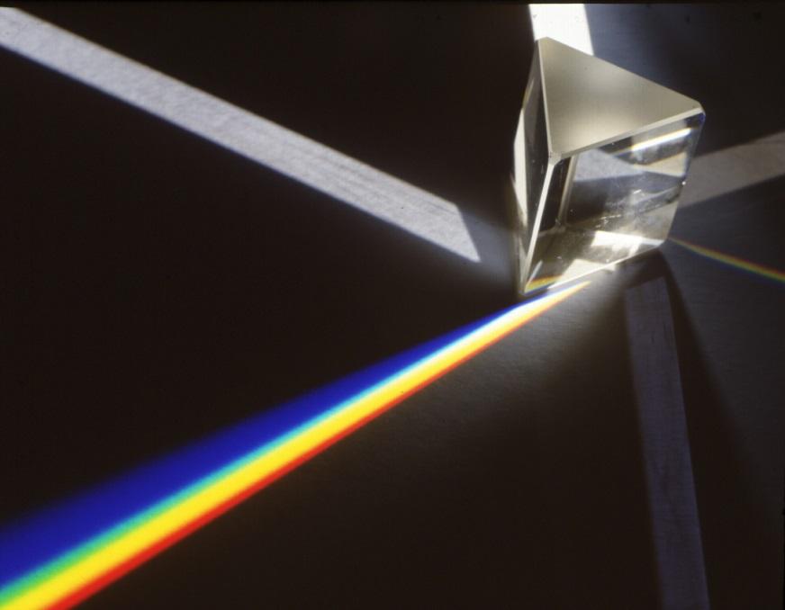
17 Dispersion Dispersion occurs because the phase velocity (and thus the index of refraction) depends on the frequency/wavelength of light Dispersive media: glass, raindrops Index of refraction: Air nn 1 λλ 1 ; Glass/water nn 2 λλ > 1 For visible light in most transparent materials, nn decreases towards 1 as the wavelength increases So blue light (λλ 400nm) bends more than red light λλ 700nm Cauchy s approximation nn λλ = AA + BB + CC λλ 2 λλ4 with material parameters A, B, C 17/36
18 Dispersion Humans have tri-stimulus color perception Allowed us to optimize rendering by only working with R, G, B However, interaction of light with an arbitrary surface cannot (in general) be described correctly using only three components Same RGB value could map to many different power distributions (and therefore wavelengths) Need to more accurately describe light and its interactions with surfaces using spectral power distributions Consider a prism dispersion setup with two orange light sources that have identical RGB values but different spectral power distributions: 18/36

19 Dispersion Glass prism lit by sodium light source Ocean Light Simulator 19/36
20 Dispersion Glass prism lit by red+green light source 20/36 Ocean Light Simulator

21 Wavelength Light Map When tracing photons from the light source, importance sample the light s spectral power distribution to obtain a λλ for each photon Use λλ and the reflectance/transmittance spectrum at each intersection point to trace the photon throughout the scene Store the incident power of the photon along with the wavelength of the photon in the photon map 21/36

22 Gathering (Camera Rays) When tracing rays from the camera, estimate the spectral power distribution at an intersection point using the nearby photon samples Multiply/Integrate this estimated spectral power distribution by the tristimulus response functions to obtain R, G, B values Requires significantly more samples in the photon map, although many optimization strategies exist 22/36
23 23/31


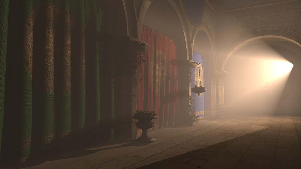
24 Atmospheric Effects Caused by light being scatted towards the camera by mist or dust 24/36
 As we move a small distance dxx along a ray, a fraction of the current radiance LL(xx, ωω) given by σσ aa xx LL xx, ωω is absorbed: dll xx, ωω = σσ aa xx LL xx, ωω dxx")
25 Absorption Light traveling through a medium may interact with the medium in such a way that the light energy is converted to another form of non-visible energy (such as heat) Define an absorption coefficient, σσ aa (xx) As we move a small distance dxx along a ray, a fraction of the current radiance LL(xx, ωω) given by σσ aa xx LL xx, ωω is absorbed: dll xx, ωω = σσ aa xx LL xx, ωω dxx 25/36
 As we move a small distance dxx along a ray, a fraction of the radiance LL(xx,")
26 Out-Scattering Light traveling through a medium in a straight line may interact with the medium and be scattered to travel off in a different direction At sunset, the atmosphere scatters away most of the blue light leaving mostly red light traveling to our eyes from the sun Define a scattering coefficient, σσ ss (xx) As we move a small distance dxx along a ray, a fraction of the radiance LL(xx, ωω) given by σσ ss xx LL xx, ωω is scattered off in another direction (and no longer travels along the ray): dll xx, ωω = σσ ss xx LL xx, ωω dxx 26/36
 given by cc(xx)ll xx, ωω is attenuated dll xx, ωω = cc(xx)ll xx, ωω dxx Both the primary rays shot from a camera pixel and the secondary shadow rays used in lighting")
27 Total Attenuation The probability light is attenuated (either absorbed or out-scattered) per unit length is cc xx = σσ aa xx + σσ ss (xx) As we move a small distance dxx along a ray, a fraction of the radiance LL(xx, ωω) given by cc(xx)ll xx, ωω is attenuated dll xx, ωω = cc(xx)ll xx, ωω dxx Both the primary rays shot from a camera pixel and the secondary shadow rays used in lighting calculations can pass through transparent objects or participating media The lighting contribution along these rays needs to be attenuated Attenuation in a participating medium can be modeled using Beer s law 27/36
 Solving this Ordinary Differential Equation (ODE) with the initial value I ( 0) = I0, results in: I( x) = I 0 e cx")
28 Recall: Beer s Law If the media is homogeneous, the attenuation along the ray can be described using Beer s Law: di = ci dx where I is the light intensity, x is the distance along the ray, and c is the attenuation constant (which varies based on color/wavelength) Solving this Ordinary Differential Equation (ODE) with the initial value I ( 0) = I0, results in: I( x) = I 0 e cx 28/36
29 Inhomogeneous Beer s Law For non-homogeneous media, the attenuation constant varies spatially based on the concentration of the inhomogeneities Discretize the ray into NN small segments, and treat the attenuation as constant over each small segment Converges to the correct answer as the number of segments is increased The attenuation along the i-th segment is set to be ee cc.5(xx ii 1+xx ii ) Δxx where Δxx = (xx NN xx 0 )/NN is the segment length, cc.5(xx ii 1 +xx ii ) is the attenuation constant evaluated at the center of the segment, and xx ii = xx 0 + iδxx The total attenuation along the ray is computed via multiplication: ee cc.5(xx 0+xx 1 ) Δxx ee cc.5(xx 1+xx 2 ) Δxx ee cc.5 xx NN 1+xx NN Δxx xx 0 xx NN Δxx 29/36
30 Attenuation Note how the smoke, acting as a participating media, casts a shadow on the ground The shadow rays cast from the ground plane to the light source have their light attenuated by the smoke volume The shadow is not completely black, since some light passes through the smoke volume 30/36
 by the")
31 Camera Rays Send out rays from the camera into the scene intersecting objects and calculating their lighting as usual For any ray that travels through participating media on the way from the camera to the object, the radiance along that ray needs to be attenuated Just like as for shadow rays An objects color could be partially attenuated or completely attenuated (not visible - occluded) by the participating media 31/36

32 Volumetric Light Map Represent a 3D light map with a uniform grid enclosing the participating media Could also use an octree, or any other spatial partition with sample points For each sample point that lies within the participating medium, send out a shadow ray to the light source and compute the attenuated radiance that reaches that sample point This computes and stores self-shadowing effects (e.g., LEFT: clouds appear darker on the side away from the light; RIGHT: smoke has light and dark regions from self-shadowing) 32/36
 Without in-scattering, the sky would appear black")
33 In-Scattering At each point along a ray, some light will be in-scattered from the surrounding medium into the direction of the ray In-scattering increases the radiance along the direction of the ray The sky appears blue because the particles in the atmosphere scatter blue light in every direction (and some of it towards our eyes) Without in-scattering, the sky would appear black 33/36
34 In-Scattering The radiance contribution due to in-scattering from the participating media needs to be added along the rays from the camera to the objects Without in-scattering, an object whose outgoing radiance was completely attenuated by participating media produces black pixels since there would be zero radiance along those rays In order to add the in-scattering contribution, add in-scattered light along each segment of the ray discretization already used for attenuation In-scattered light is added to the total light at each point, and thus gets attenuated by subsequent segments along the discretized ray Thus the calculation needs to be done from object to camera The precomputed volumetric light map stores candidate light for inscattering 34/36


35 In-Scattering At the center of each discretized segment of the camera ray, interpolate the radiance LL xx, ωω from the sample points of the volumetric light map The direction of the incoming light, ωω, is the direction from the light source to the center of the discretized segment a separate light map is needed for each light source A phase function pp(ωω, ωω ) gives the probability that an incoming ray from the light source with direction ωω is scattered into the direction of the camera ray ωω The radiance at this point xx scattered towards the camera along direction ωωω is pp ωω, ωω LL(xx, ωω)σσ ss xx The in-scattered radiance contribution from the entire discretized segment is then pp ωω, ωω LL xx, ωω σσ ss xx Δxx light dd N.B. σσ ss is the probability of any scattering in any direction, and pp selects the subset of these that scatter in the desired direction 35/36
36 Phase Functions Energy conservation: sphere pp ωω, ωω dωω = 1 Many phase functions are parameterized by the phase angle: cosθθ = ωω ωω 1. Isotropic: pp cosθθ = 1 4ππ 2. Rayleigh: pp cosθθ = cos2 θθ Models scattering due to particles smaller than the wavelength of light, such as in the atmosphere 1 4ππ 1 gg2 1+gg 2 2ggggggg 1.5 gg denotes the average phase angle and can be treated as a tunable parameter which allows one to adjust the appearance of a medium gg = 0 results in the isotropic phase function 36/36 3. Henyey-Greenstein: pp cosθθ =


37 Volumetric Emission Some participating media emit light e.g. fire Hot carbon soot emits blackbody radiation based on temperature Electrons emit light energy as they fall from higher energy excited states to lower energy states This lighting information can be added as a separate volumetric light map Note that this volumetric emission is in every direction, as opposed to the previously calculated information for self-shadowing Thus when calculating the in-scattering contribution, need to integrate the product of the phase function and incoming radiance over all incoming directions 37/36

38 Volumetric Emission Adding volumetric emission to the light map gives the desired orange/blue/etc. colors But only adding it to the light map doesn t allow for the hot carbon soot and light energy from electrons to cast shadows and light the scene To do this, need to treat this region as a volume light Often modeled by breaking it up into many small point lights similar to an area light These point lights are then used just like every other light in the scene in regards to shadow rays, creating photon maps, etc. and participate in the creation of the volumetric light map for the self shadowing of the participating media 38/36

39 39/31
 Absorption and dispersion of lens")
40 Lens Flare Light can be reflected and scattered by lenses in the lens system, resulting in generally unwanted but impressive effects This is caused in part by material inhomogeneities in the lens Model and ray trace a full optical model of the entire camera lens system Geometry of lens surfaces and characteristic planes (entrance, aperture, sensor plane) Absorption and dispersion of lens elements Antireflective coatings Diffraction 40/36
, diameter, distance between elements, index of")

41 Camera Lens Geometry The camera lens consists of a large number of elements Specify the geometry of lens elements with parameters such as radius (for spherical elements), diameter, distance between elements, index of refraction, etc. Trace rays through these elements Use Snell s law to compute the reflected/transmitted ray directions Use Fresnel Equations to compute the transmission and reflection components Canon EF-S 17-55mm f/2.8 IS USM 41/36

42 Absorption and Dispersion Light is attenuated as it moves through each lens element Treat each lens element as a participating medium with an absorption probability Lens elements are characterized by the Abbe number which measures the material s dispersion Results in chromatic aberration Model these effects using spectral rendering techniques Panasonic DMC-FZ5 by Tony & Marilyn Karp 42/36

43 Antireflective Coatings Optical coatings are applied to the surfaces of lenses to reduce reflection Characterized by a residual reflectivity RR(λλ, θθ) where λλ is the wavelength of the light and θθ is the incident angle Residual reflectivity denotes the amount of light reflected after the destructive interference of the coating is taken into account Requires spectral rendering techniques and multiple evaluations of the Fresnel equations 43/36


44 Diffraction Light tends to spread out as it goes through small openings Happens when your aperture gets too small we call this diffraction limited Tends to create constructive and destructive interference Airy disk Difficult to account for in a ray tracer due to geometric optics assumptions can fake with a texture 44/36
45 Ray Tracing Lens Flare Trace rays from the lights into the camera lens Intersect the rays with the camera lens elements Use spectral rendering to compute reflection and transmission in a physically accurate manner Store wavelength-dependent illumination samples on the film Estimate the spectral power distribution on each pixel of the film to obtain the image J.J. Abrams apologizes for being addicted to lens flare 45/36

46 Rogue One: December 16, 2016 Star Wars: December 18, /36

47 Star Wars: The Last Jedi December 15, /36


48 CS 248 Interactive Computer Graphics Making a video game
Recall: Basic Ray Tracer
 1 Recall: Ray Tracing Generate an image by backwards tracing the path of light through pixels on an image plane Simulate the interaction of light with objects Recall: Basic Ray Tracer Trace a primary ray
Visual cues to 3D geometry. Light Reflection and Advanced Shading. Shading. Recognizing materials. size (perspective) occlusion shading
 occlusion shading") Visual cues to 3D geometry Light Reflection and Advanced Shading size (perspective) occlusion shading CS 4620 Lecture 17 1 2 Shading Recognizing materials Variation in observed color across an object strongly
Visual cues to 3D geometry Light Reflection and Advanced Shading size (perspective) occlusion shading CS 4620 Lecture 17 1 2 Shading Recognizing materials Variation in observed color across an object strongly
Michelson Interferometer
 Michelson Interferometer The Michelson interferometer uses the interference of two reflected waves The third, beamsplitting, mirror is partially reflecting ( half silvered, except it s a thin Aluminum
I have a meeting with Peter Lee and Bob Cosgrove on Wednesday to discuss the future of the cluster. Computer Graphics
 Announcements Assignment 4 will be out later today Problem Set 3 is due today or tomorrow by 9am in my mail box (4 th floor NSH) How are the machines working out? I have a meeting with Peter Lee and Bob
Photon Maps. The photon map stores the lighting information on points or photons in 3D space ( on /near 2D surfaces)
") Photon Mapping 1/36 Photon Maps The photon map stores the lighting information on points or photons in 3D space ( on /near 2D surfaces) As opposed to the radiosity method that stores information on surface
Photon Mapping 1/36 Photon Maps The photon map stores the lighting information on points or photons in 3D space ( on /near 2D surfaces) As opposed to the radiosity method that stores information on surface
Specular reflection. Lighting II. Snell s Law. Refraction at boundary of media
 Specular reflection Lighting II CS 465 Lecture 19 Smooth surfaces of pure materials have ideal specular reflection (said this before) Metals (conductors) and dielectrics (insulators) behave differently
HW Chapter 20 Q 2,3,4,5,6,10,13 P 1,2,3. Chapter 20. Classic and Modern Optics. Dr. Armen Kocharian
 HW Chapter 20 Q 2,3,4,5,6,10,13 P 1,2,3 Chapter 20 Classic and Modern Optics Dr. Armen Kocharian Electromagnetic waves and matter: A Brief History of Light 1000 AD It was proposed that light consisted
Sung-Eui Yoon ( 윤성의 )
") CS380: Computer Graphics Ray Tracing Sung-Eui Yoon ( 윤성의 ) Course URL: http://sglab.kaist.ac.kr/~sungeui/cg/ Class Objectives Understand overall algorithm of recursive ray tracing Ray generations Intersection
CS380: Computer Graphics Ray Tracing Sung-Eui Yoon ( 윤성의 ) Course URL: http://sglab.kaist.ac.kr/~sungeui/cg/ Class Objectives Understand overall algorithm of recursive ray tracing Ray generations Intersection
COMPUTER GRAPHICS COURSE. LuxRender. Light Transport Foundations
 COMPUTER GRAPHICS COURSE LuxRender Light Transport Foundations Georgios Papaioannou - 2015 Light Transport Light is emitted at the light sources and scattered around a 3D environment in a practically infinite
CS354 Computer Graphics Ray Tracing. Qixing Huang Januray 24th 2017
 CS354 Computer Graphics Ray Tracing Qixing Huang Januray 24th 2017 Graphics Pipeline Elements of rendering Object Light Material Camera Geometric optics Modern theories of light treat it as both a wave
INFOGR Computer Graphics. J. Bikker - April-July Lecture 10: Shading Models. Welcome!
 INFOGR Computer Graphics J. Bikker - April-July 2016 - Lecture 10: Shading Models Welcome! Today s Agenda: Introduction Light Transport Materials Sensors Shading INFOGR Lecture 10 Shading Models 3 Introduction
Today. Participating media. Participating media. Rendering Algorithms: Participating Media and. Subsurface scattering
 Today Rendering Algorithms: Participating Media and Subsurface Scattering Introduction Rendering participating media Rendering subsurface scattering Spring 2009 Matthias Zwicker Participating media Participating
Ray Tracing. CS334 Fall Daniel G. Aliaga Department of Computer Science Purdue University
 Ray Tracing CS334 Fall 2013 Daniel G. Aliaga Department of Computer Science Purdue University Ray Casting and Ray Tracing Ray Casting Arthur Appel, started around 1968 Ray Tracing Turner Whitted, started
Recap: Refraction. Amount of bending depends on: - angle of incidence - refractive index of medium. (n 2 > n 1 ) n 2
 n 2") Amount of bending depends on: - angle of incidence - refractive index of medium Recap: Refraction λ 1 (n 2 > n 1 ) Snell s Law: When light passes from one transparent medium to another, the rays will be
Amount of bending depends on: - angle of incidence - refractive index of medium Recap: Refraction λ 1 (n 2 > n 1 ) Snell s Law: When light passes from one transparent medium to another, the rays will be
Chapter 32 Light: Reflection and Refraction. Copyright 2009 Pearson Education, Inc.
 Chapter 32 Light: Reflection and Refraction Units of Chapter 32 The Ray Model of Light Reflection; Image Formation by a Plane Mirror Formation of Images by Spherical Mirrors Index of Refraction Refraction:
Light: Geometric Optics
 Light: Geometric Optics The Ray Model of Light Light very often travels in straight lines. We represent light using rays, which are straight lines emanating from an object. This is an idealization, but
Measuring Light: Radiometry and Cameras
 Lecture 11: Measuring Light: Radiometry and Cameras Computer Graphics CMU 15-462/15-662, Fall 2015 Slides credit: a majority of these slides were created by Matt Pharr and Pat Hanrahan Simulating a pinhole
Lecture 4 Recap of PHYS110-1 lecture Physical Optics - 4 lectures EM spectrum and colour Light sources Interference and diffraction Polarization
 Lecture 4 Recap of PHYS110-1 lecture Physical Optics - 4 lectures EM spectrum and colour Light sources Interference and diffraction Polarization Lens Aberrations - 3 lectures Spherical aberrations Coma,
specular diffuse reflection.
 Lesson 8 Light and Optics The Nature of Light Properties of Light: Reflection Refraction Interference Diffraction Polarization Dispersion and Prisms Total Internal Reflection Huygens s Principle The Nature
The Rendering Equation. Computer Graphics CMU /15-662
 The Rendering Equation Computer Graphics CMU 15-462/15-662 Review: What is radiance? Radiance at point p in direction N is radiant energy ( #hits ) per unit time, per solid angle, per unit area perpendicular
Ray Tracing. CSCI 420 Computer Graphics Lecture 15. Ray Casting Shadow Rays Reflection and Transmission [Ch ]
![Ray Tracing. CSCI 420 Computer Graphics Lecture 15. Ray Casting Shadow Rays Reflection and Transmission [Ch ]](/thumbs/78/78594982.jpg "Ray Tracing. CSCI 420 Computer Graphics Lecture 15. Ray Casting Shadow Rays Reflection and Transmission [Ch ]") CSCI 420 Computer Graphics Lecture 15 Ray Tracing Ray Casting Shadow Rays Reflection and Transmission [Ch. 13.2-13.3] Jernej Barbic University of Southern California 1 Local Illumination Object illuminations
CSCI 420 Computer Graphics Lecture 15 Ray Tracing Ray Casting Shadow Rays Reflection and Transmission [Ch. 13.2-13.3] Jernej Barbic University of Southern California 1 Local Illumination Object illuminations
Announcements. Written Assignment 2 out (due March 8) Computer Graphics
 Computer Graphics") Announcements Written Assignment 2 out (due March 8) 1 Advanced Ray Tracing (Recursive) Ray Tracing Antialiasing Motion Blur Distribution Ray Tracing Ray Tracing and Radiosity Assumptions Simple shading
Announcements Written Assignment 2 out (due March 8) 1 Advanced Ray Tracing (Recursive) Ray Tracing Antialiasing Motion Blur Distribution Ray Tracing Ray Tracing and Radiosity Assumptions Simple shading
L 32 Light and Optics [3]
![L 32 Light and Optics [3]](/thumbs/78/77867745.jpg "L 32 Light and Optics [3]") L 32 Light and Optics [3] Measurements of the speed of light The bending of light refraction Total internal reflection Dispersion Dispersion Rainbows Atmospheric scattering Blue sky red sunsets Light and
L 32 Light and Optics [3] Measurements of the speed of light The bending of light refraction Total internal reflection Dispersion Dispersion Rainbows Atmospheric scattering Blue sky red sunsets Light and
Light. Electromagnetic wave with wave-like nature Refraction Interference Diffraction
 Light Electromagnetic wave with wave-like nature Refraction Interference Diffraction Light Electromagnetic wave with wave-like nature Refraction Interference Diffraction Photons with particle-like nature
CENG 477 Introduction to Computer Graphics. Ray Tracing: Shading
 CENG 477 Introduction to Computer Graphics Ray Tracing: Shading Last Week Until now we learned: How to create the primary rays from the given camera and image plane parameters How to intersect these rays
Chapter 23. Light Geometric Optics
 Chapter 23. Light Geometric Optics There are 3 basic ways to gather light and focus it to make an image. Pinhole - Simple geometry Mirror - Reflection Lens - Refraction Pinhole Camera Image Formation (the
Conceptual Physics 11 th Edition
 Conceptual Physics 11 th Edition Chapter 28: REFLECTION & REFRACTION This lecture will help you understand: Reflection Principle of Least Time Law of Reflection Refraction Cause of Refraction Dispersion
2/26/2016. Chapter 23 Ray Optics. Chapter 23 Preview. Chapter 23 Preview
 Chapter 23 Ray Optics Chapter Goal: To understand and apply the ray model of light. Slide 23-2 Chapter 23 Preview Slide 23-3 Chapter 23 Preview Slide 23-4 1 Chapter 23 Preview Slide 23-5 Chapter 23 Preview
Photorealism: Ray Tracing
 Photorealism: Ray Tracing Reading Assignment: Chapter 13 Local vs. Global Illumination Local Illumination depends on local object and light sources only Global Illumination at a point can depend on any
INFOGR Computer Graphics. J. Bikker - April-July Lecture 10: Ground Truth. Welcome!
 INFOGR Computer Graphics J. Bikker - April-July 2015 - Lecture 10: Ground Truth Welcome! Today s Agenda: Limitations of Whitted-style Ray Tracing Monte Carlo Path Tracing INFOGR Lecture 10 Ground Truth
Ray Tracing. Brian Curless CSEP 557 Fall 2016
 Ray Tracing Brian Curless CSEP 557 Fall 2016 1 Reading Required: Shirley, section 10.1-10.7 (online handout) Triangle intersection (online handout) Further reading: Shirley errata on syllabus page, needed
COMP371 COMPUTER GRAPHICS
 COMP371 COMPUTER GRAPHICS SESSION 15 RAY TRACING 1 Announcements Programming Assignment 3 out today - overview @ end of the class Ray Tracing 2 Lecture Overview Review of last class Ray Tracing 3 Local
History of Light. 5 th Century B.C.
 History of Light 5 th Century B.C. Philosophers thought light was made up of streamers emitted by the eye making contact with an object Others thought that light was made of particles that traveled from
LECTURE 37: Ray model of light and Snell's law
 Lectures Page 1 Select LEARNING OBJECTIVES: LECTURE 37: Ray model of light and Snell's law Understand when the ray model of light is applicable. Be able to apply Snell's Law of Refraction to any system.
Physics 202, Lecture 23
 Physics 202, Lecture 23 Today s Topics Lights and Laws of Geometric Optics Nature of Light Reflection and Refraction Law of Reflection Law of Refraction Index of Reflection, Snell s Law Total Internal
Lec. 7: Ch. 2 - Geometrical Optics. 1. Shadows 2. Reflection 3. Refraction 4. Dispersion. 5. Mirages, sun dogs, etc.
 Lec. 7: h. 2 - Geometrical Optics We are here 1. Shadows 2. Reflection 3. Refraction 4. Dispersion We only covered the first 44 vugraphs. 5. Mirages, sun dogs, etc. Read hapter 3, skip 3.3 and skip 3.5D
EECS 487: Interactive Computer Graphics
 Ray Tracing EECS 487: Interactive Computer Graphics Lecture 29: Distributed Ray Tracing Introduction and context ray casting Recursive ray tracing shadows reflection refraction Ray tracing implementation
What is it? How does it work? How do we use it?
 What is it? How does it work? How do we use it? Dual Nature http://www.youtube.com/watch?v=dfpeprq7ogc o Electromagnetic Waves display wave behavior o Created by oscillating electric and magnetic fields
Ch. 22 Properties of Light HW# 1, 5, 7, 9, 11, 15, 19, 22, 29, 37, 38
 Ch. 22 Properties of Light HW# 1, 5, 7, 9, 11, 15, 19, 22, 29, 37, 38 Brief History of the Nature of Light Up until 19 th century, light was modeled as a stream of particles. Newton was a proponent of
dq dt I = Irradiance or Light Intensity is Flux Φ per area A (W/m 2 ) Φ =
 Φ =") Radiometry (From Intro to Optics, Pedrotti -4) Radiometry is measurement of Emag radiation (light) Consider a small spherical source Total energy radiating from the body over some time is Q total Radiant
Radiometry (From Intro to Optics, Pedrotti -4) Radiometry is measurement of Emag radiation (light) Consider a small spherical source Total energy radiating from the body over some time is Q total Radiant
Schedule. MIT Monte-Carlo Ray Tracing. Radiosity. Review of last week? Limitations of radiosity. Radiosity
 Schedule Review Session: Tuesday November 18 th, 7:30 pm, Room 2-136 bring lots of questions! MIT 6.837 Monte-Carlo Ray Tracing Quiz 2: Thursday November 20 th, in class (one weeks from today) MIT EECS
Chapter 5 Mirror and Lenses
 Chapter 5 Mirror and Lenses Name: 5.1 Ray Model of Light Another model for light is that it is made up of tiny particles called. Photons travel in perfect, lines from a light source This model helps us
Computer Graphics. Si Lu. Fall uter_graphics.htm 11/22/2017
 Computer Graphics Si Lu Fall 2017 http://web.cecs.pdx.edu/~lusi/cs447/cs447_547_comp uter_graphics.htm 11/22/2017 Last time o Splines 2 Today o Raytracing o Final Exam: 14:00-15:30, Novermber 29, 2017
INTRODUCTION REFLECTION AND REFRACTION AT BOUNDARIES. Introduction. Reflection and refraction at boundaries. Reflection at a single surface
 Chapter 8 GEOMETRICAL OPTICS Introduction Reflection and refraction at boundaries. Reflection at a single surface Refraction at a single boundary Dispersion Summary INTRODUCTION It has been shown that
Chapter 26 Geometrical Optics
 Chapter 26 Geometrical Optics 1 Overview of Chapter 26 The Reflection of Light Forming Images with a Plane Mirror Spherical Mirrors Ray Tracing and the Mirror Equation The Refraction of Light Ray Tracing
Phys 1020, Day 18: Questions? Cameras, Blmfld Reminders: Next Up: digital cameras finish Optics Note Final Project proposals next week!
 Lights. Action. Phys 1020, Day 18: Questions? Cameras, Blmfld 15.1 Reminders: Next Up: digital cameras finish Optics Note Final Project proposals next week! 1 What have we learned in this section: 1) Lasers
Topic 9: Lighting & Reflection models 9/10/2016. Spot the differences. Terminology. Two Components of Illumination. Ambient Light Source
 Topic 9: Lighting & Reflection models Lighting & reflection The Phong reflection model diffuse component ambient component specular component Spot the differences Terminology Illumination The transport
AP Physics: Curved Mirrors and Lenses
 The Ray Model of Light Light often travels in straight lines. We represent light using rays, which are straight lines emanating from an object. This is an idealization, but is very useful for geometric
Refraction of Light. This bending of the ray is called refraction
 Refraction & Lenses Refraction of Light When a ray of light traveling through a transparent medium encounters a boundary leading into another transparent medium, part of the ray is reflected and part of
Topic 9: Lighting & Reflection models. Lighting & reflection The Phong reflection model diffuse component ambient component specular component
 Topic 9: Lighting & Reflection models Lighting & reflection The Phong reflection model diffuse component ambient component specular component Spot the differences Terminology Illumination The transport
Introduction to Computer Vision. Introduction CMPSCI 591A/691A CMPSCI 570/670. Image Formation
 Introduction CMPSCI 591A/691A CMPSCI 570/670 Image Formation Lecture Outline Light and Optics Pinhole camera model Perspective projection Thin lens model Fundamental equation Distortion: spherical & chromatic
Advanced Graphics. Path Tracing and Photon Mapping Part 2. Path Tracing and Photon Mapping
 Advanced Graphics Path Tracing and Photon Mapping Part 2 Path Tracing and Photon Mapping Importance Sampling Combine importance sampling techniques Reflectance function (diffuse + specular) Light source
Pre-Lab Quiz / PHYS 224 Dispersion and Prism
 Pre-Lab Quiz / PHYS 224 Dispersion and Prism Name Lab Section 1. What do we investigate in this lab? 2. Describe Snell s Law and draw a diagram. 3. As shown in Figure 4, the specific angle of the prism
3 Interactions of Light Waves
 CHAPTER 22 3 Interactions of Light Waves SECTION The Nature of Light BEFORE YOU READ After you read this section, you should be able to answer these questions: How does reflection affect the way we see
CS 563 Advanced Topics in Computer Graphics Camera Models. by Kevin Kardian
 CS 563 Advanced Topics in Computer Graphics Camera Models by Kevin Kardian Introduction Pinhole camera is insufficient Everything in perfect focus Less realistic Different camera models are possible Create
Consider a partially transparent object that is illuminated with two lights, one visible from each side of the object. Start with a ray from the eye
 Ray Tracing What was the rendering equation? Motivate & list the terms. Relate the rendering equation to forward ray tracing. Why is forward ray tracing not good for image formation? What is the difference
Distribution Ray-Tracing. Programação 3D Simulação e Jogos
 Distribution Ray-Tracing Programação 3D Simulação e Jogos Bibliography K. Suffern; Ray Tracing from the Ground Up, http://www.raytracegroundup.com Chapter 4, 5 for Anti-Aliasing Chapter 6 for Disc Sampling
Lecture 7 Notes: 07 / 11. Reflection and refraction
 Lecture 7 Notes: 07 / 11 Reflection and refraction When an electromagnetic wave, such as light, encounters the surface of a medium, some of it is reflected off the surface, while some crosses the boundary
dq dt I = Irradiance or Light Intensity is Flux Φ per area A (W/m 2 ) Φ =
 Φ =") Radiometry (From Intro to Optics, Pedrotti -4) Radiometry is measurement of Emag radiation (light) Consider a small spherical source Total energy radiating from the body over some time is Q total Radiant
Radiometry (From Intro to Optics, Pedrotti -4) Radiometry is measurement of Emag radiation (light) Consider a small spherical source Total energy radiating from the body over some time is Q total Radiant
Chapter 24 - The Wave Nature of Light
 Chapter 24 - The Wave Nature of Light Summary Four Consequences of the Wave nature of Light: Diffraction Dispersion Interference Polarization Huygens principle: every point on a wavefront is a source of
GEOMETRIC OPTICS. LENSES refract light, so we need to know how light bends when entering and exiting a lens and how that interaction forms an image.
 I. What is GEOMTERIC OPTICS GEOMETRIC OPTICS In geometric optics, LIGHT is treated as imaginary rays. How these rays interact with at the interface of different media, including lenses and mirrors, is
Nicholas J. Giordano. Chapter 24. Geometrical Optics. Marilyn Akins, PhD Broome Community College
 Nicholas J. Giordano www.cengage.com/physics/giordano Chapter 24 Geometrical Optics Marilyn Akins, PhD Broome Community College Optics The study of light is called optics Some highlights in the history
Chapter 26 Geometrical Optics
 Chapter 26 Geometrical Optics 26.1 The Reflection of Light 26.2 Forming Images With a Plane Mirror 26.3 Spherical Mirrors 26.4 Ray Tracing and the Mirror Equation 26.5 The Refraction of Light 26.6 Ray
index of refraction-light speed
 AP Physics Study Guide Chapters 22, 23, 24 Reflection, Refraction and Interference Name Write each of the equations specified below, include units for all quantities. Law of Reflection Lens-Mirror Equation
MIT Monte-Carlo Ray Tracing. MIT EECS 6.837, Cutler and Durand 1
 MIT 6.837 Monte-Carlo Ray Tracing MIT EECS 6.837, Cutler and Durand 1 Schedule Review Session: Tuesday November 18 th, 7:30 pm bring lots of questions! Quiz 2: Thursday November 20 th, in class (one weeks
Chapter 36. Image Formation
 Chapter 36 Image Formation Apr 22, 2012 Light from distant things We learn about a distant thing from the light it generates or redirects. The lenses in our eyes create images of objects our brains can
Lighting and Shading
 Lighting and Shading Today: Local Illumination Solving the rendering equation is too expensive First do local illumination Then hack in reflections and shadows Local Shading: Notation light intensity in,
CPSC GLOBAL ILLUMINATION
 CPSC 314 21 GLOBAL ILLUMINATION Textbook: 20 UGRAD.CS.UBC.CA/~CS314 Mikhail Bessmeltsev ILLUMINATION MODELS/ALGORITHMS Local illumination - Fast Ignore real physics, approximate the look Interaction of
So far, we have considered only local models of illumination; they only account for incident light coming directly from the light sources.
 11 11.1 Basics So far, we have considered only local models of illumination; they only account for incident light coming directly from the light sources. Global models include incident light that arrives
Light and Electromagnetic Waves. Honors Physics
 Light and Electromagnetic Waves Honors Physics Electromagnetic Waves EM waves are a result of accelerated charges and disturbances in electric and magnetic fields (Radio wave example here) As electrons
Lecture 24 EM waves Geometrical optics
 Physics 2102 Jonathan Dowling Lecture 24 EM waves Geometrical optics EM spherical waves The intensity of a wave is power per unit area. If one has a source that emits isotropically (equally in all directions)
Diffraction Diffraction occurs when light waves is passed by an aperture/edge Huygen's Principal: each point on wavefront acts as source of another
 Diffraction Diffraction occurs when light waves is passed by an aperture/edge Huygen's Principal: each point on wavefront acts as source of another circular wave Consider light from point source at infinity
Distributed Ray Tracing
 Distributed Ray Tracing 1996-2018 Josef Pelikán CGG MFF UK Praha pepca@cgg.mff.cuni.cz http://cgg.mff.cuni.cz/~pepca/ DistribRT 2018 Josef Pelikán, http://cgg.mff.cuni.cz/~pepca 1 / 24 Distributed ray
CMSC427 Shading Intro. Credit: slides from Dr. Zwicker
 CMSC427 Shading Intro Credit: slides from Dr. Zwicker 2 Today Shading Introduction Radiometry & BRDFs Local shading models Light sources Shading strategies Shading Compute interaction of light with surfaces
Basic optics. Geometrical optics and images Interference Diffraction Diffraction integral. we use simple models that say a lot! more rigorous approach
 Basic optics Geometrical optics and images Interference Diffraction Diffraction integral we use simple models that say a lot! more rigorous approach Basic optics Geometrical optics and images Interference
Light & Optical Systems Reflection & Refraction. Notes
 Light & Optical Systems Reflection & Refraction Notes What is light? Light is electromagnetic radiation Ultra-violet + visible + infra-red Behavior of Light Light behaves in 2 ways particles (photons)
Lecture Outline Chapter 26. Physics, 4 th Edition James S. Walker. Copyright 2010 Pearson Education, Inc.
 Lecture Outline Chapter 26 Physics, 4 th Edition James S. Walker Chapter 26 Geometrical Optics Units of Chapter 26 The Reflection of Light Forming Images with a Plane Mirror Spherical Mirrors Ray Tracing
Distributed Ray Tracing
 CT5510: Computer Graphics Distributed Ray Tracing BOCHANG MOON Distributed Ray Tracing Motivation The classical ray tracing produces very clean images (look fake) Perfect focus Perfect reflections Sharp
Conceptual Physics Fundamentals
 Conceptual Physics Fundamentals Chapter 14: PROPERTIES OF LIGHT This lecture will help you understand: Reflection Refraction Dispersion Total Internal Reflection Lenses Polarization Properties of Light
Diffraction. Single-slit diffraction. Diffraction by a circular aperture. Chapter 38. In the forward direction, the intensity is maximal.
 Diffraction Chapter 38 Huygens construction may be used to find the wave observed on the downstream side of an aperture of any shape. Diffraction The interference pattern encodes the shape as a Fourier
GG450 4/5/2010. Today s material comes from p and in the text book. Please read and understand all of this material!
 GG450 April 6, 2010 Seismic Reflection I Today s material comes from p. 32-33 and 81-116 in the text book. Please read and understand all of this material! Back to seismic waves Last week we talked about
Global Illumination. CMPT 361 Introduction to Computer Graphics Torsten Möller. Machiraju/Zhang/Möller
 Global Illumination CMPT 361 Introduction to Computer Graphics Torsten Möller Reading Foley, van Dam (better): Chapter 16.7-13 Angel: Chapter 5.11, 11.1-11.5 2 Limitation of local illumination A concrete
Reflection and Shading
 Reflection and Shading R. J. Renka Department of Computer Science & Engineering University of North Texas 10/19/2015 Light Sources Realistic rendering requires that we model the interaction between light
Global Illumination The Game of Light Transport. Jian Huang
 Global Illumination The Game of Light Transport Jian Huang Looking Back Ray-tracing and radiosity both computes global illumination Is there a more general methodology? It s a game of light transport.
CS201 Computer Vision Lect 4 - Image Formation
 CS201 Computer Vision Lect 4 - Image Formation John Magee 9 September, 2014 Slides courtesy of Diane H. Theriault Question of the Day: Why is Computer Vision hard? Something to think about from our view
Understanding Variability
 Understanding Variability Why so different? Light and Optics Pinhole camera model Perspective projection Thin lens model Fundamental equation Distortion: spherical & chromatic aberration, radial distortion
PHYS 219 General Physics: Electricity, Light and Modern Physics
 PHYS 219 General Physics: Electricity, Light and Modern Physics Exam 2 is scheduled on Tuesday, March 26 @ 8 10 PM In Physics 114 It will cover four Chapters 21, 22, 23, and 24. Start reviewing lecture
Lec. 6: Ch. 2 - Geometrical Optics
 Lec. 6: Ch. 2 - Geometrical Optics We are here 1. Shadows 2. Reflection 3. Refraction 4. Dispersion Guest lecture Tuesday, February 2, by Dr. Greg Werner. 1 Review Equal angle rule Similar triangles are
Light and Sound. Wave Behavior and Interactions
 Light and Sound Wave Behavior and Interactions How do light/sound waves interact with matter? WORD Definition Example Picture REFLECTED REFRACTED is the change in direction of a wave when it changes speed
Computergrafik. Matthias Zwicker Universität Bern Herbst 2016
 Computergrafik Matthias Zwicker Universität Bern Herbst 2016 Today More shading Environment maps Reflection mapping Irradiance environment maps Ambient occlusion Reflection and refraction Toon shading
Lighting. To do. Course Outline. This Lecture. Continue to work on ray programming assignment Start thinking about final project
 To do Continue to work on ray programming assignment Start thinking about final project Lighting Course Outline 3D Graphics Pipeline Modeling (Creating 3D Geometry) Mesh; modeling; sampling; Interaction
Movie: For The Birds. Announcements. Ray Tracing 1. Programming 2 Recap. Programming 3 Info Test data for part 1 (Lines) is available
 is available") Now Playing: Movie: For The Birds Pixar, 2000 Liar Built To Spill from You In Reverse Released April 11, 2006 Ray Tracing 1 Rick Skarbez, Instructor COMP 575 November 1, 2007 Announcements Programming
Now Playing: Movie: For The Birds Pixar, 2000 Liar Built To Spill from You In Reverse Released April 11, 2006 Ray Tracing 1 Rick Skarbez, Instructor COMP 575 November 1, 2007 Announcements Programming
Lighting & 3D Graphics. Images from 3D Creative Magazine
 Lighting & 3D Graphics Images from 3D Creative Magazine Contents Introduction Definitions 3D Lighting Basics 3D Light Sources Lighting Controls & Effects Brightness & Colour Shadows Hotspot And Falloff
Where n = 0, 1, 2, 3, 4
 Syllabus: Interference and diffraction introduction interference in thin film by reflection Newton s rings Fraunhofer diffraction due to single slit, double slit and diffraction grating Interference 1.
Refraction at a single curved spherical surface
 Refraction at a single curved spherical surface This is the beginning of a sequence of classes which will introduce simple and complex lens systems We will start with some terminology which will become
Problem Set 4 Part 1 CMSC 427 Distributed: Thursday, November 1, 2007 Due: Tuesday, November 20, 2007
 Problem Set 4 Part 1 CMSC 427 Distributed: Thursday, November 1, 2007 Due: Tuesday, November 20, 2007 Programming For this assignment you will write a simple ray tracer. It will be written in C++ without
Radiometry (From Intro to Optics, Pedrotti 1-4) Radiometry is measurement of Emag radiation (light) Consider a small spherical source Assume a black
 Radiometry is measurement of Emag radiation (light) Consider a small spherical source Assume a black") Radiometry (From Intro to Optics, Pedrotti -4) Radiometry is measurement of Emag radiation (light) Consider a small spherical source Assume a black body type emitter: uniform emission Total energy radiating
Radiometry (From Intro to Optics, Pedrotti -4) Radiometry is measurement of Emag radiation (light) Consider a small spherical source Assume a black body type emitter: uniform emission Total energy radiating
Chapter 33 Continued Properties of Light. Law of Reflection Law of Refraction or Snell s Law Chromatic Dispersion Brewsters Angle
 Chapter 33 Continued Properties of Light Law of Reflection Law of Refraction or Snell s Law Chromatic Dispersion Brewsters Angle Dispersion: Different wavelengths have different velocities and therefore
Lecture 5 Chapter 1 & 2. Sources of light
 We are here Lecture 5 Chapter 1 & 2 Some history of technology How vision works What is light Wavelength and Frequency: c = f λ Scientific notation and metric units Electromagnetic spectrum Transmission
Chapter 7: Geometrical Optics. The branch of physics which studies the properties of light using the ray model of light.
 Chapter 7: Geometrical Optics The branch of physics which studies the properties of light using the ray model of light. Overview Geometrical Optics Spherical Mirror Refraction Thin Lens f u v r and f 2