Overview of ABAQUS II. Working with Geometry in ABAQUS III. Working with models Created Outside ABAQUS IV. Material and Section Properties
|
|
|
- Griffin Marshall
- 5 years ago
- Views:
Transcription
1 ABAQUS TRAINING I. Overview of ABAQUS II. Working with Geometry in ABAQUS III. Working with models Created Outside ABAQUS IV. Material and Section Properties V. Assemblies in ABAQUS VI. Steps, Output, Loads and Boundary Conditions VII. Meshing Native Geometry and Exporting Mesh VIII. Meshing Techniques IX. Constraints and Interactions X. Job Management and Results Visualization XI. Stress Concentration Factors (SCF) XII. Common Error Messages
2 CONTENTS Session 1 I. Overview of ABAQUS II. III. Working with Geometry in ABAQUS Working with models Created Outside ABAQUS 2
3 CHAPTER I. Overview of ABAQUS 3
4 What is ABAQUS? The heart of ABAQUS are the analysis modules, ABAQUS/Standard and ABAQUS/Explicit, which are complementary and integrated analysis tools ABAQUS/Standard is a general purpose, finite element module. It provides a large number of capabilities for analyzing many different types of problems, including many nonstructural applications. ABAQUS/Explicit is an explicit dynamic finite element module. ABAQUS/CAE incorporates the analysis modules into a Complete ABAQUS Environment for modeling, managing and monitoring ABAQUS analyses and visualizing results. 4
5 Comparing ABAQUS/Standard and ABAQUS/Explicit A general-purpose finite element program Nonlinear problems require iterations A general-purpose finite element program for explicit dynamics. Solution procedure does not require iteration. Can solve for true static equilibrium in structural simulations. Solves highly discontinuous highspeed dynamic problems efficiently. Provides a large number of capabilities for analyzing many different types of problems. Nonstrctural applications Coupled or uncoupled response Coupled-field analyses include: Thermal-mechanical Structural-acoustic 5

6 Modern graphical user interface of menus, icons, and dialog boxes Menus provide access to all capabilities Dialog boxes allow you to input alphanumeric information and to select various options Icons accelerate access to frequently used features 6

7 Consistent environment Functionality is presented in modules Each module contains a logical subset of the overall functionality Once you understand the presentation of one module, you can easily understand the presentation of the other modules. 7


8 Part -Create the part geometry Property - Define materials -Define and assign sections to parts Assembly - Position parts for initial configuration. Assembly is created for models with only one part Step - Define analysis steps and output requests Interaction - Define contact and other interactions and assign them to steps in the analysis history Load -Apply loads, BCs and assign them to steps in the analysis history Mesh -Split assembly into meshable regions and mesh Job - Submit, manage and monitor analysis job. - Examine results Visualization 8
9 Model Tree The Model Tree provides you with a graphical overview of your model and the objects that it contains It provides a convenient, centralized tool for moving between modules and for managing objects Some features of the model tree are discussed next 9
10 Feature-based and parametric A feature is a meaningful piece of the design. Models are constructed from numerous features; for example Geometric features Solid extrusion, wire, cut, fillet, etc. Mesh features Partition the mesh into different regions for different meshing techniques, seed different edges with different mesh densities, etc. 10


11 A parameter is a modifiable quantity that provides additional information for a feature; for example: Solid extrusion parameters Sketch of extrusion cross-section, depth of extrusion. Cut Sketch of cut cross-section, depth of cut. Fillet Fillet radius. 11

12 Features often have parent-child relationships, such that the existence of the child depends on the existence of the parent; for example: Delete the solid extrusion, and the hole cannot exist. Delete the solid extrusion, and the fillet cannot exist. Delete the part, and the mesh cannot exist. ABAQUS/CAE always asks to make sure that you want to delete the parents and its child features. Parent: solid extrusion Child: cut Child: fillet Example of Parent-Child Relationships among Features 12
13 The model database (file extension.cae) Only one model database can be opened in ABAQUS/CAE at a time Replay (.rpy) file All commands executed during a session including any mistakes, are saved in this file Journal (.jnl) file All commands necessary to recreate the most currently saved model database (.cae) are saved in this file. Recover (.rec) file All commands necessary to recreate the model database (.cae) since it was most recently saved are saved in this file. Input (.inp) file ABAQUS input files Output (.odb) file ABAQUS output files 13
14 ABAQUS Conventions UNITS ABAQUS uses no inherit sets of units It is the user s responsibility to use consistent units COORDINATE SYSTEMS For boundary conditions and point loads, the default coordinate system is the rectangular Cartesian system. Alternative local rectangular, cylindrical, and spherical systems can be defined. These local directions do not rotate with the material in large- displacement analyses. MATERIAL DIRECTIONS The default coordinate systems depends on the element type: Solid elements use global rectangular Cartesian system. Shell and membrane elements use a projection of the global rectangular Cartesian system onto the surface. 14
15 CHAPTER II. Working with Geometry in ABAQUS 15

16 PARTS Geometry built directly in ABAQUS/CAE Geometry built using the tools available in the Part module. Called native geometry A part created using the Part Module tools has a feature-based representation Geometry imported from CAD systems Native CAD geometry Neutral formats Imported geometry does not have a feature-based representation 16

17 PARTS Parts can be scaled and/or mirrored while copying This is available for both geometry and orphan meshes 17


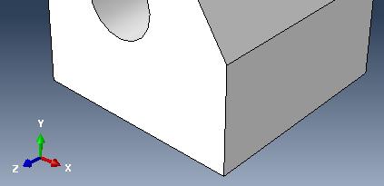
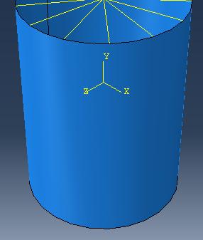
18 Building PART Using Part Module Tool 18
19 Building PART Using Part Module Tool 19


20 Building PART Using Part Module Tool Datum geometry A datum is a reference geometry or a construction aid that helps you create a feature when the part does not contain the necessary geometry. A datum is a feature of a part and is regenerated along with the rest of the part. A datum can be turned on and off for viewing. Types of datum features: point, axis, coordinate system, plane 20
21 Building PART Using Part Module Tool Partitioning in the Part module Partitioning subdivides the part into different regions. Each region must be assigned material and cross-sectional properties. Every instance of the part in the assembly has the same partitions. Regions can be used for creating geometry sets and for meshing. Geometry sets created in the Part module are also available in the assembly-level modules. Partitioning to create meshable regions often is better done in the Assembly and Mesh modules 21


22 Building PART Using Part Module Tool Invoking the Sketcher When you create a base feature, ABAQUS/CAE automatically invokes the Sketcher with a blank sheet of virtual graph paper. An alternative is to create a stand-alone sketch using the Sketch module. Such sketches are not initially associated with a part but can be used later 22
23 Building PART Using Part Module Tool Using the Sketcher The Sketcher toolset provides the basic drawing tools necessary to create moderately complex sketches. 23
24 Building PART Using Part Module Tool Trimming, extending, breaking, and merging edges Trim/extend edges Breaks the edges at intersection Auto-trim Based on pre-selection Does not break the intersecting edges Break edges Creates separate pieces with a common vertex Merge edges Close small gaps in a sketch 24
25 Building PART Using Part Module Tool Dimensions in the Sketcher After creating sketch geometry, you can add dimensions between geometric entities in the sketch You can refine the sketch by modifying the dimension values. The sketch actively changes to reflect the new dimension values Dimensions serve as comments for future reference. 25


26 Building PART Using Part Module Tool Adding features to a base feature When adding sketched features to a base feature, select the sketching plane from a planar face on the part or a datum plane. You can control the sketch orientation by selecting a planar face and an edge. By default, the edge will appear vertical and on the right side of the sketch. 26


27 Building PART Using Part Module Tool 27


28 Geometry Repair Repair options Tools are available for manually repairing geometry: Repair part by merging small edges and surfaces to make it valid Replace or remove faces Create cells using existing faces Stitch small gaps Etc. 28
29 CONTENTS III. Working with models Created Outside ABAQUS 29


30 Orphan Mesh Import An existing mesh can be imported from an ABAQUS input (.inp) or output database (.odb) file The mesh is called an orphan mesh because it has no associated parent geometry 30


31 Orphan Mesh Import By default the imported mesh is considered a single part The Part Copy tool, however, can be used to separate disconnected regions of the model into individual parts. 31


32 Orphan Mesh Import Orphan mesh editing Even though an orphan mesh has no associated geometry, modifications can be made to the mesh within the Mesh module. A suite of mesh editing tools is provided: Create nodes or elements Change one or more coordinates of a set of nodes Verify and flip shell element normals Convert elements from first-order to second order and vice versa Re-mesh a planar, triangular orphan mesh 32
33 Orphan Mesh Import Re-meshing of planar orphan meshes Mesh consists of either first or second order triangular elements; re-meshed based on boundary sizes or new uniform global size. Overall material area is preserved. 33


34 Orphan Mesh Export A native mesh created in ABAQUS mesh module can be exported by creating a mesh part. The mesh part is also called an orphan mesh because it has no associated parent geometry When creating a mesh part, all the pre-defined sets will not be available. New sets need to be defined for the newly created mesh part. 34
35 CONTENTS Session 2 I. Material and Section Properties II. III. Assemblies in ABAQUS Steps, Output, Loads and Boundary Conditions 35
36 CHAPTER I. Material and Section Properties 36
37 ABAQUS Material Models ABAQUS has an extensive material library that can be used to model most engineering materials, including: Metals Plastics Rubbers Foams Composites Concrete Geo-materials In this session we discuss the most commonly used material models Linear elasticity Metal Plasticity 37
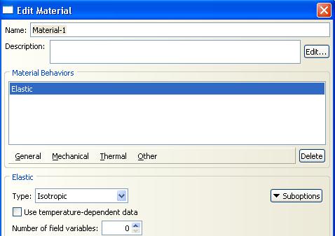
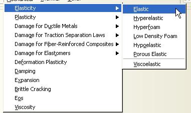
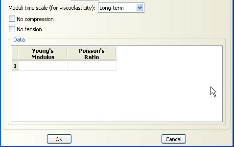
38 Linear Elasticity Most materials have some range of deformation in which their behavior remains elastic. Quite frequently, as in the case of ductile metals, the range of elastic behavior is very limited. A linear elastic material model: Is valid for small elastic strains (normally less than 5%); Can be isotropic, orthotropic, or fully anistropic; and Can have properties that depend on temperature and/or other field variables. Orthotropic and anisotropic material definitions require the use of local material directions 38
39 For a linear elastic material, Hooke s law states stress α strain The generalized form of the law is written as σ = D el : ε el Linear Elasticity where σ is the Cauchy (or true ) stress, D el is the fourth-order elasticity tensor, and ε el is the elastic log strain Uniaxial stress-strain curve for a linear elastic material 39
40 40
41 Metal Plasticity Typical uniaxial stress-strain data for an elastic-plastic solid metal are shown below: When most metals are loaded below their yield point, their behavior is approximately linear and elastic. If the stress in the metal is greater than the yield stress, most metals begin to deform plastically 41
42 Metal Plasticity In most metals the yield stress is a small fraction-typically 1/10% to 1% of the elastic modulus. Thus, the elastic strain in the metal is never more than this same fraction: 1/10% to 1%. Consequently, the elastic response of the metal can be modeled as linear. In ABAQUS all metal plasticity models are associated with linear elasticity. A very large change in modulus occurs at yield If the material is strained beyond yield and the strain is then reversed, the material immediately recovers its elastic stiffness. 42
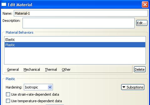
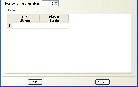
43 Metal Plasticity Hardening The yield surface may change as a result of plastic deformation. The change in the yield surface is defined by the hardening law. The following hardening laws are available in ABAQUS: Perfect plasticity Isotropic hardening Intended for applications such as crash analyses, metal forming, and general collapse studies Kinematic hardening Combined isotropic/kinematic hardening Intended for applications involving cyclic loading Johnson-Cook plasticity Well suited to model high-strain rate deformation of metals; only available in ABAQUS/Explicit 43
44 44


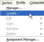
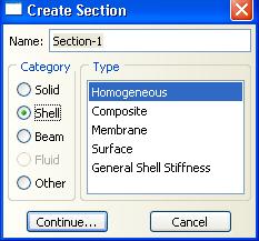
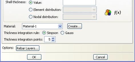
45 Profile Properties Section properties contain additional dimensional or element-type information necessary for applying material properties to a deformable body. E.g, the thickness of a shell or two-dimensional solid or the cross-sectional dimensions of a beam are considered section properties. 45


 or during")
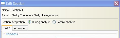
46 Section Properties For beams and shells the stiffness of the section is computed numerically by integrating the section properties The stiffness may be computed either before the analysis (done once, efficient for linear analysis) or during the analysis 46
47 Section Properties 47
48 CHAPTER II. Assemblies in ABAQUS 48
49 What is an Assembly? An assembly contains all the geometry included in the finite element model. Each ABAQUS/CAE model contains a single assembly. An assembly is empty initially even if you have created some parts. An assembly does not contain parts directly; instead, it contains instances of parts. For convenience, instances can be turned on and off for viewing. The following points explain the relationship between parts, part instances, and assemblies. 49
50 What is an Assembly? Parts You create parts in the Part module Each part is a distinct geometric entity that can be modified and manipulated independently of other parts Each part exists in its own coordinate system and has no knowledge of other parts Each part has it owns references section properties 50
51 What is an Assembly? Part instances and assemblies You create instances of your parts in the Assembly module An instance always maintains its association with the original part You can create instance of a part many times and assemble multiple instances of the same part Each instance of the part is associated with the section properties assigned to the part in the Property module You position part instances relative to each other in a global coordinate system to form the assembly You can modify the original part, and ABAQUS/CAE updates any instances of that part when you return to the Assembly module. 51


52 What is an Assembly? Dependent and independent part instances You can create either independent or dependent part instances. An independent instance is effectively a copy of the part and can be modified A dependent instance shares the geometry and the mesh of the original part and cannot be modified. Dependent instances are created by default 52
53 What is an Assembly? 53

54 Positioning Part instances Positioning is the main task in the Assembly module. Two general methods Absolute positioning Relative positioning Absolute positioning is not treated as a feature of the assembly Translation Rotation Replace one part with another 54
55 Sets and Surfaces Sets define regions from one or more parts or part instances for: Loads and boundary conditions Generating output during the analysis Surfaces define regions from one or more parts or part instances for specifying: Contact Distributed loads Sets and surface are useful when certain geometric groups will be used for multiple purposes. Note: Often it is more convenient to select geometric entities directly using the mouse when defining loads, boundary conditions, and fields rather than using sets and surfaces. One advantage of sets is that you provide names that will be meaningful for results visualization. 55
56 Sets and Surfaces Sets and Surfaces can be defined at the part level or the assembly level (i.e, associated with the part instance rather than the part itself) Part sets appear in the Model Tree in a Set container under the part with which they are associated. Sets from an instanced part appear in the Model Tree under the assembly. Part sets are also available in the assembly-related modules. Only read-only access to these sets is provided in the assembly-related modules. 56
57 CHAPTER III. Steps, Output, Loads and Boundary Conditions 57
58 Analysis Steps and Procedures A basic concept in ABAQUS is the division of the problem history into steps. A step is any convenient phase of the history a thermal transient, a creep hold, a dynamic transient, etc. In its simplest form a step can be just a static analysis of a load change from one magnitude to another. For each step the user chooses an analysis procedure. This choice defines the type of analysis to be performed during the step: static stress analysis, dynamic stress analysis, eigenvalue buckling, transient heat transfer analysis, etc. The rest of the step definition consists of load, boundary, and output request specifications. 58
59 Analysis Steps and Procedures ABAQUS distinguishes between two kinds of analysis procedure: General analysis procedures Response can be linear or nonlinear Steps that use general procedures are known as general steps The starting point for each general step is the state of the model at the end of the last general step. Linear pertubation procedures Response can only be linear. The linear pertubation is about a base state, which can be either the initial or the current configuration of the model. Response prior to reaching the base state can be nonlinear Steps that use linear procedures are known as pertubation steps 59


60 Analysis Steps and Procedures Defining Steps in ABAQUS/CAE 60

 and X-Y plots.")
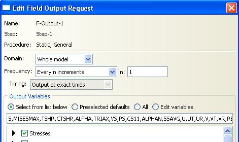
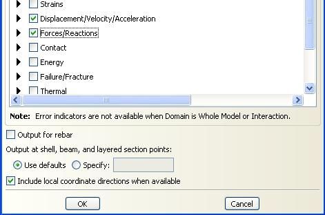
61 Output Two types of output data: field and history data Field data is used for model (deformed, contour, etc.) and X-Y plots. History data is used for X-Y plots. 61

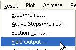
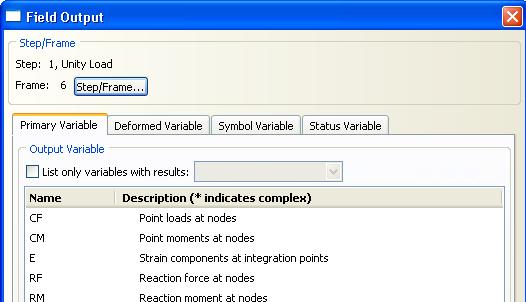
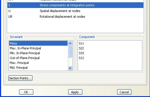
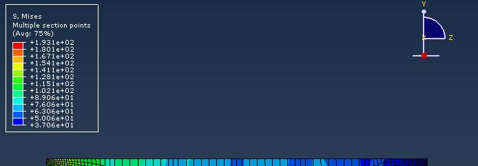
62 Field Output 62

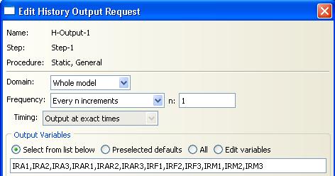
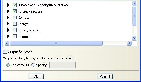
63 History Output 63
64 Loads and Boundary Conditions In ABAQUS the term load (as in the Load module in ABAQUS/CAE) generally refers to anything that includes a change in the response of a structure from its initial state, including: Concentrated forces, Surface tractions (e.g., pressure, shear, etc.) Nonzero boundary conditions, Body loads, and Temperature (with thermal expansion of the material defined) Sometimes the term refers specially to force-type quantities (as in the Load Manager of the Load module); for example, Concentrated forces, pressures, and body loads but not boundary conditions or temperature. 64
65 Loads and Boundary Conditions 65


66 Loads Defining loads and boundary conditions in ABAQUS/CAE Create a load (or boundary condition), and select the steps in which it will be active. 66


 Edit the load (or boundary condition) to specify")
67 Loads Select the application region (geometry, nodes, or elements selected directly using the mouse or sets and surfaces defined previously) (Surfaces on orphan meshes can be selected by picking one element face and a feature angle. Individual edits make it easy to clean up anomalies.) Edit the load (or boundary condition) to specify magnitude, etc. 67
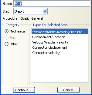
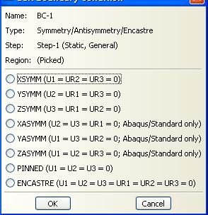
68 Boundary Conditions 68

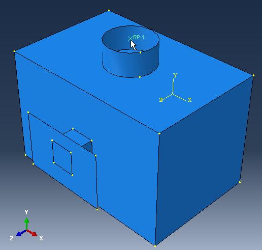
69 Reference Point 69
70 CONTENTS Session 3 I. Meshing Native Geometry and Exporting Mesh II. III. Meshing Techniques Constraints and Interactions 70
71 CHAPTER I. Meshing Native Geometry and Exporting Mesh 71
72 Meshing Native Geometry General capabilities of the Mesh module Allows you to mesh an assembly using various levels of automation, and controls to suit the needs of your analysis Assign mesh attributes, and set mesh controls to specify: Meshing technique Element shape Element type Mesh density Generate the mesh Query and verify the mesh for: Number of nodes and elements Element type Element quality 72
73 Dependent and Independent Part Instances You can create either independent or dependent part instances Independent instances can be modified (e.g., they can be partitioned). Dependent instances cannot be modified (e.g., they cannot be partitioned) Dependent instances share the same geometry and mesh of the original part so any modifications must be made to the original part. Attributes (loads, BCs, etc.) and sets/surfaces can be created, however. All instances of a part must be either dependent or independent No mixture is allowed for a given part All orphan mesh instances must be dependent 73


74 Dependent and Independent Part Instances Choose Independent or Dependent when creating part instance Independent not allowed if: Part is meshed Part has Virtual Topology Dependent instances of Part already exist Part is an orphan mesh Dependent not allowed if: Independent instances of Part already exist Can easily convert between dependent and independent 74
75 Exporting Mesh Allows you to export mesh of an assembly by creating a mesh part The mesh part created become an orphan mesh instances The mesh part is then being imported back to Assembly Module as dependent part All the sets/surfaces defined earlier have to be redefined Mesh part is useful when you want to duplicate the same mesh either by revolving, mirror and etc. These mesh part can also be exported to other FE analysis software. 75


76 Exporting Mesh Steps in creating mesh part and exporting mesh 76
77 CHAPTER II. Meshing Techniques 77
78 Meshing Techniques Free meshing Free meshing uses no pre-established mesh patterns, making it impossible to predict a free mesh pattern before creating mesh Element shape options available for free meshing two-dimensional regions: Quadrilateral (default) Can be applied to any planar or curved surface Quadrilateral dominated Allows some triangular elements for transition Triangular can be applied to any planar or curved surface 78
79 Meshing Techniques 79
80 Meshing Techniques Two-dimensional swept meshes All-quad meshing of swept regions Planar or curved surfaces Quad-dominated meshing of degenerate revolved regions (Degenerate regions include the axis of revolution) 80
81 Meshing Techniques Swept Meshing Swept solid regions can be filled with: Hex meshes Hex-dominated meshes Wedge meshes The swept path can be: Straight line Circular arc Spline 81
82 Meshing Techniques Limitation Source and target faces must be planar Constant cross-sections only Target face and each side wall must have only one face. 82


83 Meshing Techniques Structured meshing The structured meshing technique generates meshes using simple predefined mesh topologies ABAQUS transforms the mesh of a regularly shaped region, such as a square or a cube, onto the geometry of the region you want to mesh. Structured meshing generally gives the most control over the mesh. 83


84 Meshing Techniques Which regions are meshable? ABAQUS/CAE automatically determines meshability for each region based on its geometry and mesh controls Regions are color coded to indicate their currently assigned meshing technique 84


85 Meshing Techniques Partitioning to make regions meshable Most three-dimensional part instances require partitioning to permit hexahedral meshing Complex geometries often can be partitioned into simpler, meshable regions. Partitioning can be used to: Change and simplify the topology so that the regions can be meshed using primarily hexahedral elements with the structured or swept meshing techniques. 85
86 Mesh Compatibility 86
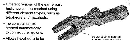
87 Mesh Compatibility Currently it is not possible to automatically obtain meshes that are compatible between part instances If mesh compatibility is required between two or more bodies, first try to create a single part that contains all the bodies. - Multiple part instances can be merged into a single part instance in the Assembly module - Different material regions can be separated using partitions. If the two objects must be modeled as separate parts, consider using tie constraints to glue two regions together. Alternatively, merge instance meshes into a conforming orphan mesh. Tied surfaces Using tie constraints to glue the cylinder to the block: exploded view of assembly (top) and mesh 87

88 Controlling Mesh Density and Gradation Mesh seeds Mesh seeds are markers that you define along the edges of a region to specify the desired, or target, mesh density. 88
89 Controlling Mesh Density and Gradation You can set a typical global element length for part instances. ABAQUS/CAE automatically creates mesh seed along all relevant edges based on the typical element length. New edges created by partitioning automatically inherit the global mesh seeds. You can override the global mesh seed with local mesh seeds along selected edges Edge mesh seeds can be uniform or biased. Edge mesh seeds propagate automatically from the selected edge to the matching edges for swept meshable regions. 89


90 Controlling Mesh Density and Gradation Global seeds (black) and local seeds (magenta) 90


91 Controlling Mesh Density and Gradation Partitioning into different mesh regions Partitioning creates additional edges, which allows more control over local mesh density. Each mesh region can have different mesh controls. Partitioning and local mesh seeding allows you to refine mesh in the area of a stress concentration. 91

92 Assigning Element Types The available element types depend on the geometry of your model You can assign the element type either before or after you create the mesh Different element types can be assigned to different regions of your model Items such as loads and boundary conditions depend on the uunderlying geometry, not the mesh, so performing parametric studies on mesh density or element types is very easy 92

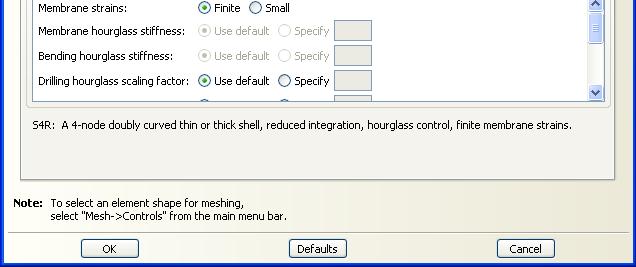
93 Assigning Element Types 93
94 Element in ABAQUS Family A family of finite elements is the broadest category used to classify elements. Elements in the same family share many basic features. There are many variations within a family. 94
95 Element in ABAQUS 95
96 Element in ABAQUS Integration The stiffness and mass of an element are calculated numerically at sampling points called integration points: within the element The numerical algorithm used to integrate these variables influences how an element behaves Full Integration The minimum integration order required for exact integration of the strain energy for an undistorted element with linear material properties. Reduced Integration The integration rule that is one order less than the full integration rule. 96
97 CHAPTER III. Constraints and Interactions 97

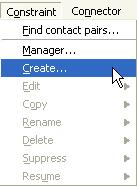
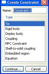
98 Interaction - Constraints What are constraints? Constraints allow you to model kinematic relationship between points Tie constraints Allow you to fuse together two regions even though the meshes created on the surfaces of the regions may be dissimilar Easy mesh transitioning It provides a simple way to bond surfaces together permanently Surface-based constraint using a master-slave formulation The constraint prevents slave nodes from separating or sliding relative to the master surface 98
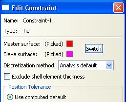
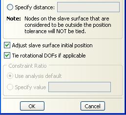
99 Constraints - Tie 99
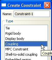
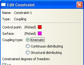
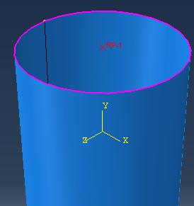
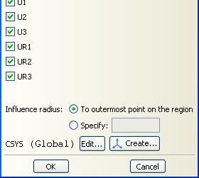
100 Constraints - Coupling 100
101 CONTENTS Session 4 I. Job Management and Results Visualization II. III. IV. Stress Concentration Factors (SCF) Common Error Messages Tutorial 1 Linear Static Analysis 101
102 CHAPTER I. Job Management and Results Visualization 102
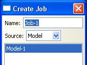
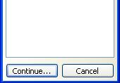
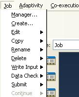
103 Job Management 103
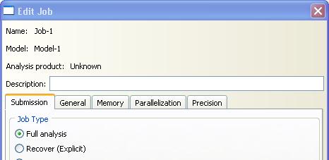
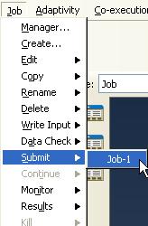
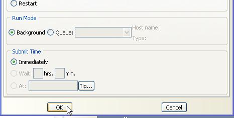
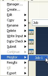
104 Job Management 104
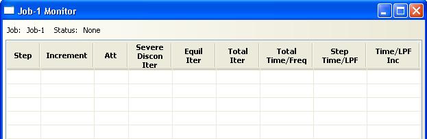
105 Job Management 105
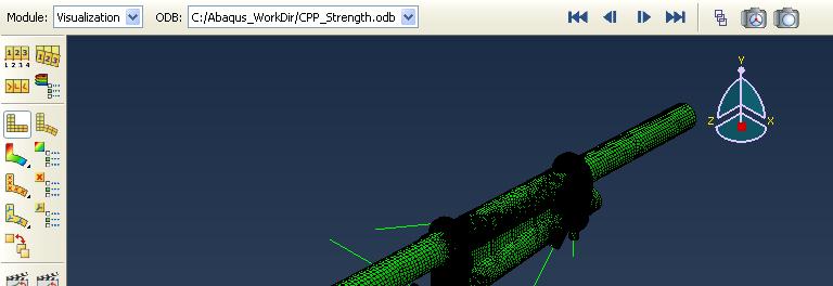
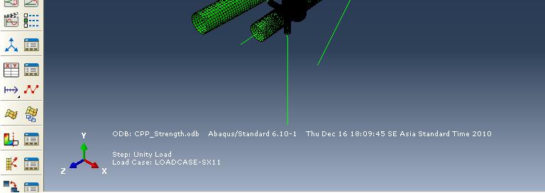
106 Results Visualization 106
107 Results Visualization 107
108 Results Visualization 108
109 CHAPTER II. Stress Concentration Factors (SCF) 109
110 Stress Concentration Second-order elements clearly outperform first-order elements in problems with stress concentrations and are ideally suited for the analysis of (stationary) cracks Both full integrated and reduced-integration element work well. Reduced-integration elements tend to be somewhere more efficient results are often as good or better than full integration at lower computational cost. Second-order elements capture geometric features, such as curved edges, with fewer elements than first-order elements 110
111 Stress Concentration 111
112 Stress Concentration Second-order elements give much better results Well-shaped, second order, reduced-integration quadrilaterals and hexahedra can provide high accuracy in stress concentration regions Distorted elements reduce the accuracy in these regions 112
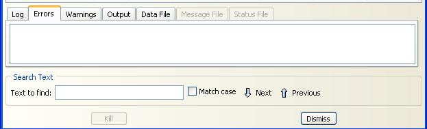
113 CHAPTER III. Common Error Messages 113

114 Common Errors Do not apply boundary conditions to the slave nodes of a tie constraint. This will cause the nodes to be overconstrained, resulting in errors in the analysis. Symptoms: Zero pivot warnings in the JOB Diagnostics dialog box and the message (.msg) file in ABAQUS/Standard 114
Appendix B: Creating and Analyzing a Simple Model in Abaqus/CAE
 Getting Started with Abaqus: Interactive Edition Appendix B: Creating and Analyzing a Simple Model in Abaqus/CAE The following section is a basic tutorial for the experienced Abaqus user. It leads you
3. Preprocessing of ABAQUS/CAE
 3.1 Create new model database 3. Preprocessing of ABAQUS/CAE A finite element analysis in ABAQUS/CAE starts from create new model database in the toolbar. Then save it with a name user defined. To build
Creating and Analyzing a Simple Model in Abaqus/CAE
 Appendix B: Creating and Analyzing a Simple Model in Abaqus/CAE The following section is a basic tutorial for the experienced Abaqus user. It leads you through the Abaqus/CAE modeling process by visiting
Introduction to Abaqus. About this Course
 Introduction to Abaqus R 6.12 About this Course Course objectives Upon completion of this course you will be able to: Use Abaqus/CAE to create complete finite element models. Use Abaqus/CAE to submit and
Workshop 15. Single Pass Rolling of a Thick Plate
 Introduction Workshop 15 Single Pass Rolling of a Thick Plate Rolling is a basic manufacturing technique used to transform preformed shapes into a form suitable for further processing. The rolling process
Torsional-lateral buckling large displacement analysis with a simple beam using Abaqus 6.10
 Torsional-lateral buckling large displacement analysis with a simple beam using Abaqus 6.10 This document contains an Abaqus tutorial for performing a buckling analysis using the finite element program
SimLab Release Notes. 1 A l t a i r E n g i n e e r i n g
 SimLab 11.0 Release Notes 1 A l t a i r E n g i n e e r i n g System Support extended to load and save GDA/SLB files of size greater than 4GB. Memory allocation is enhanced to support large models. Kubrix
Fully-Coupled Thermo-Mechanical Analysis
 Fully-Coupled Thermo-Mechanical Analysis Type of solver: ABAQUS CAE/Standard Adapted from: ABAQUS Example Problems Manual Extrusion of a Cylindrical Aluminium Bar with Frictional Heat Generation Problem
Abaqus CAE Tutorial 6: Contact Problem
 ENGI 7706/7934: Finite Element Analysis Abaqus CAE Tutorial 6: Contact Problem Problem Description In this problem, a segment of an electrical contact switch (steel) is modeled by displacing the upper
FINITE ELEMENT ANALYSIS OF A PLANAR TRUSS
 Problem Description: FINITE ELEMENT ANALYSIS OF A PLANAR TRUSS Instructor: Professor James Sherwood Revised: Dimitri Soteropoulos Programs Utilized: Abaqus/CAE 6.11-2 This tutorial explains how to build
Abaqus/CAE: Geometry Import and Meshing
 Abaqus/CAE: Geometry Import and Meshing Day 1 Overview of Abaqus/CAE Lecture 1 Demonstration 1 Demonstration 2 Workshop 1 Workshop 2 Workshop 3 Geometry Import and Repair Geometry Import and Repair: Lens
Installation Guide. Beginners guide to structural analysis
 Installation Guide To install Abaqus, students at the School of Civil Engineering, Sohngaardsholmsvej 57, should log on to \\studserver, whereas the staff at the Department of Civil Engineering should
Abaqus/CAE (ver. 6.11) Nonlinear Buckling Tutorial
 Nonlinear Buckling Tutorial") Abaqus/CAE (ver. 6.11) Nonlinear Buckling Tutorial Problem Description This is the NAFEMS 1 proposed benchmark (Lee s frame buckling) problem. The applied load is based on the normalized (EI/L 2 ) value
Abaqus/CAE (ver. 6.11) Nonlinear Buckling Tutorial Problem Description This is the NAFEMS 1 proposed benchmark (Lee s frame buckling) problem. The applied load is based on the normalized (EI/L 2 ) value
CE366/ME380 Finite Elements in Applied Mechanics I Fall 2007
 CE366/ME380 Finite Elements in Applied Mechanics I Fall 2007 FE Project 1: 2D Plane Stress Analysis of acantilever Beam (Due date =TBD) Figure 1 shows a cantilever beam that is subjected to a concentrated
A pipe bend is subjected to a concentrated force as shown: y All dimensions in inches. Material is stainless steel.
 Problem description A pipe bend is subjected to a concentrated force as shown: y 15 12 P 9 Displacement gauge Cross-section: 0.432 18 x 6.625 All dimensions in inches. Material is stainless steel. E =
ME 475 FEA of a Composite Panel
 ME 475 FEA of a Composite Panel Objectives: To determine the deflection and stress state of a composite panel subjected to asymmetric loading. Introduction: Composite laminates are composed of thin layers
Abaqus/CAE Axisymmetric Tutorial (Version 2016)
") Abaqus/CAE Axisymmetric Tutorial (Version 2016) Problem Description A round bar with tapered diameter has a total load of 1000 N applied to its top face. The bottom of the bar is completely fixed. Determine
Abaqus/CAE Axisymmetric Tutorial (Version 2016) Problem Description A round bar with tapered diameter has a total load of 1000 N applied to its top face. The bottom of the bar is completely fixed. Determine
SolidWorks. An Overview of SolidWorks and Its Associated Analysis Programs
 An Overview of SolidWorks and Its Associated Analysis Programs prepared by Prof. D. Xue University of Calgary SolidWorks - a solid modeling CAD tool. COSMOSWorks - a design analysis system fully integrated
Using MSC.Nastran for Explicit FEM Simulations
 3. LS-DYNA Anwenderforum, Bamberg 2004 CAE / IT III Using MSC.Nastran for Explicit FEM Simulations Patrick Doelfs, Dr. Ingo Neubauer MSC.Software GmbH, D-81829 München, Patrick.Doelfs@mscsoftware.com Abstract:
Femap Version
 Femap Version 11.3 Benefits Easier model viewing and handling Faster connection definition and setup Faster and easier mesh refinement process More accurate meshes with minimal triangle element creation
Example 24 Spring-back
 Example 24 Spring-back Summary The spring-back simulation of sheet metal bent into a hat-shape is studied. The problem is one of the famous tests from the Numisheet 93. As spring-back is generally a quasi-static
ME Optimization of a Frame
 ME 475 - Optimization of a Frame Analysis Problem Statement: The following problem will be analyzed using Abaqus. 4 7 7 5,000 N 5,000 N 0,000 N 6 6 4 3 5 5 4 4 3 3 Figure. Full frame geometry and loading
Generative Part Structural Analysis Fundamentals
 CATIA V5 Training Foils Generative Part Structural Analysis Fundamentals Version 5 Release 19 September 2008 EDU_CAT_EN_GPF_FI_V5R19 About this course Objectives of the course Upon completion of this course
Surfacing using Creo Parametric 3.0
 Surfacing using Creo Parametric 3.0 Overview Course Code Course Length TRN-4506-T 3 Days In this course, you will learn how to use various techniques to create complex surfaces with tangent and curvature
Problem description. It is desired to analyze the cracked body shown using a 3D finite element mesh: Top view. 50 radius. Material properties:
 Problem description It is desired to analyze the cracked body shown using a 3D finite element mesh: Top view 30 50 radius 30 Material properties: 5 2 E = 2.07 10 N/mm = 0.29 All dimensions in mm Crack
TRINITAS. a Finite Element stand-alone tool for Conceptual design, Optimization and General finite element analysis. Introductional Manual
 TRINITAS a Finite Element stand-alone tool for Conceptual design, Optimization and General finite element analysis Introductional Manual Bo Torstenfelt Contents 1 Introduction 1 2 Starting the Program
PTC Creo Simulate. Features and Specifications. Data Sheet
 PTC Creo Simulate PTC Creo Simulate gives designers and engineers the power to evaluate structural and thermal product performance on your digital model before resorting to costly, time-consuming physical
CHAPTER 4. Numerical Models. descriptions of the boundary conditions, element types, validation, and the force
 CHAPTER 4 Numerical Models This chapter presents the development of numerical models for sandwich beams/plates subjected to four-point bending and the hydromat test system. Detailed descriptions of the
Abaqus/CAE: Geometry Import and Meshing. Abaqus 2018
 Abaqus/CAE: Geometry Import and Meshing Abaqus 2018 About this Course Course objectives Upon completion of this course you will be able to: Import, edit, and repair CAD geometry. Import and edit orphan
Customized Pre/post-processor for DIANA. FX for DIANA
 Customized Pre/post-processor for DIANA FX for DIANA About FX4D for DIANA FX4D is a general purpose pre/post-processor for CAE simulation. FX4D has been specialized for civil/architectural applications.
Geometric Modeling. Introduction
 Geometric Modeling Introduction Geometric modeling is as important to CAD as governing equilibrium equations to classical engineering fields as mechanics and thermal fluids. intelligent decision on the
Introduction to ANSYS DesignModeler
 Lecture 5 Modeling 14. 5 Release Introduction to ANSYS DesignModeler 2012 ANSYS, Inc. November 20, 2012 1 Release 14.5 Preprocessing Workflow Geometry Creation OR Geometry Import Geometry Operations Meshing
ABAQUS for CATIA V5 Tutorials
 ABAQUS for CATIA V5 Tutorials AFC V2.5 Nader G. Zamani University of Windsor Shuvra Das University of Detroit Mercy SDC PUBLICATIONS Schroff Development Corporation www.schroff.com ABAQUS for CATIA V5,
Revision of the SolidWorks Variable Pressure Simulation Tutorial J.E. Akin, Rice University, Mechanical Engineering. Introduction
 Revision of the SolidWorks Variable Pressure Simulation Tutorial J.E. Akin, Rice University, Mechanical Engineering Introduction A SolidWorks simulation tutorial is just intended to illustrate where to
This tutorial will take you all the steps required to import files into ABAQUS from SolidWorks
 ENGN 1750: Advanced Mechanics of Solids ABAQUS CAD INTERFACE TUTORIAL School of Engineering Brown University This tutorial will take you all the steps required to import files into ABAQUS from SolidWorks
2: Static analysis of a plate
 2: Static analysis of a plate Topics covered Project description Using SolidWorks Simulation interface Linear static analysis with solid elements Finding reaction forces Controlling discretization errors
Sliding Split Tube Telescope
 LESSON 15 Sliding Split Tube Telescope Objectives: Shell-to-shell contact -accounting for shell thickness. Creating boundary conditions and loads by way of rigid surfaces. Simulate large displacements,
Manual for Computational Exercises
 Manual for the computational exercise in TMM4160 Fracture Mechanics Page 1 of 32 TMM4160 Fracture Mechanics Manual for Computational Exercises Version 3.0 Zhiliang Zhang Dept. of Structural Engineering
Manipulating the Boundary Mesh
 Chapter 7. Manipulating the Boundary Mesh The first step in producing an unstructured grid is to define the shape of the domain boundaries. Using a preprocessor (GAMBIT or a third-party CAD package) you
Impact and Postbuckling Analyses
 ABAQUS/Explicit: Advanced Topics Lecture 8 Impact and Postbuckling Analyses ABAQUS/Explicit: Advanced Topics L8.2 Overview Geometric Imperfections for Postbuckling Analyses ABAQUS/Explicit: Advanced Topics
Chapter 5 Modeling and Simulation of Mechanism
 Chapter 5 Modeling and Simulation of Mechanism In the present study, KED analysis of four bar planar mechanism using MATLAB program and ANSYS software has been carried out. The analysis has also been carried
SimLab 14.1 Release Notes
 SimLab 14.1 Release Notes Highlights SimLab 14.0 introduced the new user interface. SimLab 14.1 enhances the user interface using feedback from customers. In addition many new core features have been added.
Revised Sheet Metal Simulation, J.E. Akin, Rice University
 Revised Sheet Metal Simulation, J.E. Akin, Rice University A SolidWorks simulation tutorial is just intended to illustrate where to find various icons that you would need in a real engineering analysis.
Manual for Abaqus CAE Topology Optimization
 Abaqus CAE access: Manual for Abaqus CAE Topology Optimization 1. Open Exceed ondemand Client -> login and pass 2FA 2. Select Desktop_Mode_Full_Screen (or other user preferred resolution) for XConfig and
NX Advanced FEM. fact sheet
 Advanced FEM fact sheet www.ugs.com Summary Advanced FEM is a comprehensive multi-cad finite element modeling and results visualization product that is designed to meet the needs of experienced CAE analysts.
EN1740 Computer Aided Visualization and Design Spring /26/2012 Brian C. P. Burke
 EN1740 Computer Aided Visualization and Design Spring 2012 4/26/2012 Brian C. P. Burke Last time: More motion analysis with Pro/E Tonight: Introduction to external analysis products ABAQUS External Analysis
Abaqus/CAE (ver. 6.10) Stringer Tutorial
 Stringer Tutorial") Abaqus/CAE (ver. 6.10) Stringer Tutorial Problem Description A table made of steel tubing with a solid steel top and shelf is loaded with an oblique impulse load. Determine the transient response of the
Abaqus/CAE (ver. 6.10) Stringer Tutorial Problem Description A table made of steel tubing with a solid steel top and shelf is loaded with an oblique impulse load. Determine the transient response of the
Finite Element Analysis Using Pro/Engineer
 Appendix A Finite Element Analysis Using Pro/Engineer A.1 INTRODUCTION Pro/ENGINEER is a three-dimensional product design tool that promotes practices in design while ensuring compliance with industry
Engineering Effects of Boundary Conditions (Fixtures and Temperatures) J.E. Akin, Rice University, Mechanical Engineering
 J.E. Akin, Rice University, Mechanical Engineering") Engineering Effects of Boundary Conditions (Fixtures and Temperatures) J.E. Akin, Rice University, Mechanical Engineering Here SolidWorks stress simulation tutorials will be re-visited to show how they
Engineering Effects of Boundary Conditions (Fixtures and Temperatures) J.E. Akin, Rice University, Mechanical Engineering Here SolidWorks stress simulation tutorials will be re-visited to show how they
Validation Report: Additional Data Mapping to Structural Analysis Packages
 Autodesk Moldflow Structural Alliance 2012 Validation Report: Additional Data Mapping to Structural Analysis Packages Mapping process-induced stress data from Autodesk Moldflow Insight Dual Domain and
Abaqus/CAE Heat Transfer Tutorial
 Abaqus/CAE Heat Transfer Tutorial Problem Description The thin L shaped steel part shown above (lengths in meters) is exposed to a temperature of 20 o C on the two surfaces of the inner corner, and 120
ANSYS 5.6 Tutorials Lecture # 2 - Static Structural Analysis
 R50 ANSYS 5.6 Tutorials Lecture # 2 - Static Structural Analysis Example 1 Static Analysis of a Bracket 1. Problem Description: The objective of the problem is to demonstrate the basic ANSYS procedures
Embedded Reinforcements
 Embedded Reinforcements Gerd-Jan Schreppers, January 2015 Abstract: This paper explains the concept and application of embedded reinforcements in DIANA. Basic assumptions and definitions, the pre-processing
SETTLEMENT OF A CIRCULAR FOOTING ON SAND
 1 SETTLEMENT OF A CIRCULAR FOOTING ON SAND In this chapter a first application is considered, namely the settlement of a circular foundation footing on sand. This is the first step in becoming familiar
Finite Element Method. Chapter 7. Practical considerations in FEM modeling
 Finite Element Method Chapter 7 Practical considerations in FEM modeling Finite Element Modeling General Consideration The following are some of the difficult tasks (or decisions) that face the engineer
Education Curriculum Surface Design Specialist
 Education Curriculum Surface Design Specialist Invest your time in imagining next generation designs. Here s what we will teach you to give shape to your imagination. CATIA Surface Design Specialist CATIA
MSC/PATRAN LAMINATE MODELER COURSE PAT 325 Workbook
 MSC/PATRAN LAMINATE MODELER COURSE PAT 325 Workbook P3*V8.0*Z*Z*Z*SM-PAT325-WBK - 1 - - 2 - Table of Contents Page 1 Composite Model of Loaded Flat Plate 2 Failure Criteria for Flat Plate 3 Making Plies
Element Order: Element order refers to the interpolation of an element s nodal results to the interior of the element. This determines how results can
 TIPS www.ansys.belcan.com 鲁班人 (http://www.lubanren.com/weblog/) Picking an Element Type For Structural Analysis: by Paul Dufour Picking an element type from the large library of elements in ANSYS can be
SAMCEF for ROTORS. Chapter 3.2: Rotor modeling. This document is the property of SAMTECH S.A. MEF A, Page 1
 SAMCEF for ROTORS Chapter 3.2: Rotor modeling This document is the property of SAMTECH S.A. MEF 101-03-2-A, Page 1 Table of contents Introduction Introduction 1D Model 2D Model 3D Model 1D Models: Beam-Spring-
CHAPTER 1. Introduction
 ME 475: Computer-Aided Design of Structures 1-1 CHAPTER 1 Introduction 1.1 Analysis versus Design 1.2 Basic Steps in Analysis 1.3 What is the Finite Element Method? 1.4 Geometrical Representation, Discretization
Multi-Step Analysis of a Cantilever Beam
 LESSON 4 Multi-Step Analysis of a Cantilever Beam LEGEND 75000. 50000. 25000. 0. -25000. -50000. -75000. 0. 3.50 7.00 10.5 14.0 17.5 21.0 Objectives: Demonstrate multi-step analysis set up in MSC/Advanced_FEA.
SOLIDWORKS 2016: A Power Guide for Beginners and Intermediate Users
 SOLIDWORKS 2016: A Power Guide for Beginners and Intermediate Users The premium provider of learning products and solutions www.cadartifex.com Table of Contents Dedication... 3 Preface... 15 Part 1. Introducing
ABAQUS/CAE Workshops
 ABAQUS/CAE Workshops University of Birmingham ABAQUS Training 27 th / 28 th October 2009 Workshop 1a: Create 3D Part Type: abaqus cae at the command prompt or select abaqus V6.9-1 from the start menu.
Linear and Nonlinear Analysis of a Cantilever Beam
 LESSON 1 Linear and Nonlinear Analysis of a Cantilever Beam P L Objectives: Create a beam database to be used for the specified subsequent exercises. Compare small vs. large displacement analysis. Linear
Introduction to Solid Modeling Parametric Modeling. Mechanical Engineering Dept.
 Introduction to Solid Modeling Parametric Modeling 1 Why draw 3D Models? 3D models are easier to interpret. Simulation under real-life conditions. Less expensive than building a physical model. 3D models
Abaqus 6.9SE Handout
 MANE 4240/ CIVL 4240: Introduction to Finite Elements Abaqus 6.9SE Handout Professor Suvranu De Department of Mechanical, Aerospace and Nuclear Engineering Rensselaer Polytechnic Institute Table of Contents
NX Advanced FEM. Benefits
 Advanced FEM fact sheet Siemens PLM Software www.siemens.com/plm Summary Advanced FEM software is a comprehensive multi-cad finite element modeling and results visualization product that is designed to
Nouveautés ANSYS pour le calcul structurel et l impression 3D. CADFEM 2017 ANSYS Additive Manufacturing
 Titelmasterformat Journée Technologique durch AddiPole Klicken bearbeiten Nouveautés ANSYS pour le calcul structurel et l impression 3D Titelmasterformat Structural design with durch ANSYS Klicken bearbeiten
ANSYS AIM Tutorial Stepped Shaft in Axial Tension
 ANSYS AIM Tutorial Stepped Shaft in Axial Tension Author(s): Sebastian Vecchi, ANSYS Created using ANSYS AIM 18.1 Contents: Problem Specification 3 Learning Goals 4 Pre-Analysis & Start Up 5 Calculation
NEi FEA. IRONCAD Advanced FEA. IRONCAD Advanced FEA. NEi FEA
 2011 Overview has been designed as a universal, adaptive and user-friendly graphical user interface for geometrical modeling, data input and visualization of results for all types of numerical simulation
Abaqus CAE Tutorial 1: 2D Plane Truss
 ENGI 7706/7934: Finite Element Analysis Abaqus CAE Tutorial 1: 2D Plane Truss Lab TA: Xiaotong Huo EN 3029B xh0381@mun.ca Download link for Abaqus student edition: http://academy.3ds.com/software/simulia/abaqus-student-edition/
Structural & Thermal Analysis Using the ANSYS Workbench Release 12.1 Environment
 ANSYS Workbench Tutorial Structural & Thermal Analysis Using the ANSYS Workbench Release 12.1 Environment Kent L. Lawrence Mechanical and Aerospace Engineering University of Texas at Arlington SDC PUBLICATIONS
PTC Newsletter January 14th, 2002
 PTC Email Newsletter January 14th, 2002 PTC Product Focus: Pro/MECHANICA (Structure) Tip of the Week: Creating and using Rigid Connections Upcoming Events and Training Class Schedules PTC Product Focus:
Recent Advances on Higher Order 27-node Hexahedral Element in LS-DYNA
 14 th International LS-DYNA Users Conference Session: Simulation Recent Advances on Higher Order 27-node Hexahedral Element in LS-DYNA Hailong Teng Livermore Software Technology Corp. Abstract This paper
Introduction to MSC.Patran
 Exercise 1 Introduction to MSC.Patran Objectives: Create geometry for a Beam. Add Loads and Boundary Conditions. Review analysis results. MSC.Patran 301 Exercise Workbook - Release 9.0 1-1 1-2 MSC.Patran
SimLab 14.2 Release Notes
 SimLab 14.2 Release Notes Highlights SimLab 14.2 comes with various changes that improve performance and graphics rendering. In addition to java scripting, python scripting is introduced. The enhancements,
Wound Composite Modeler For Abaqus. Abaqus Version SIMULIA, Inc. User s Manual
 Wound Composite Modeler For Abaqus Abaqus Version 6.7-3 2007 SIMULIA, Inc. User s Manual Table of Contents 1. Background... 3 1.1 Plug-in Overview... 3 2. Underlying Dome Geometry... 5 2.1 Geodesic Dome...
SIMULATION CAPABILITIES IN CREO
 SIMULATION CAPABILITIES IN CREO Enhance Your Product Design with Simulation & Using digital prototypes to understand how your designs perform in real-world conditions is vital to your product development
Analysis Steps 1. Start Abaqus and choose to create a new model database
 Source: Online tutorials for ABAQUS Problem Description The two dimensional bridge structure, which consists of steel T sections (b=0.25, h=0.25, I=0.125, t f =t w =0.05), is simply supported at its lower
This tutorial will take you all the steps required to set up and run a basic simulation using ABAQUS/CAE and visualize the results;
 ENGN 1750: Advanced Mechanics of Solids ABAQUS TUTORIAL School of Engineering Brown University This tutorial will take you all the steps required to set up and run a basic simulation using ABAQUS/CAE and
Linear Elastic Fracture Mechanics (LEFM) Analysis of Flaws within Residual Stress Fields
 Analysis of Flaws within Residual Stress Fields") Linear Elastic Fracture Mechanics (LEFM) Analysis of Flaws within Residual Stress Fields David Woyak 1, Brian Baillargeon, Ramesh Marrey, and Randy Grishaber 2 1 Dassault Systemés SIMULIA Corporation &
Linear Elastic Fracture Mechanics (LEFM) Analysis of Flaws within Residual Stress Fields David Woyak 1, Brian Baillargeon, Ramesh Marrey, and Randy Grishaber 2 1 Dassault Systemés SIMULIA Corporation &
Finite Element Analysis Using Creo Simulate 4.0
 Introduction to Finite Element Analysis Using Creo Simulate 4.0 Randy H. Shih SDC PUBLICATIONS Better Textbooks. Lower Prices. www.sdcpublications.com Powered by TCPDF (www.tcpdf.org) Visit the following
NX I-deas MasterFEM Complete standalone capabilities for creating FE models and evaluating simulation results
 I-deas MasterFEM Complete standalone capabilities for creating FE models and evaluating simulation results fact sheet Siemens PLM Software www.siemens.com/nx Summary I-deas MasterFEM software is the standalone
Metafor FE Software. 2. Operator split. 4. Rezoning methods 5. Contact with friction
 ALE simulations ua sus using Metafor eao 1. Introduction 2. Operator split 3. Convection schemes 4. Rezoning methods 5. Contact with friction 1 Introduction EULERIAN FORMALISM Undistorted mesh Ideal for
Guidelines for proper use of Plate elements
 Guidelines for proper use of Plate elements In structural analysis using finite element method, the analysis model is created by dividing the entire structure into finite elements. This procedure is known
Quarter Symmetry Tank Stress (Draft 4 Oct 24 06)
") Quarter Symmetry Tank Stress (Draft 4 Oct 24 06) Introduction You need to carry out the stress analysis of an outdoor water tank. Since it has quarter symmetry you start by building only one-fourth of
Quarter Symmetry Tank Stress (Draft 4 Oct 24 06) Introduction You need to carry out the stress analysis of an outdoor water tank. Since it has quarter symmetry you start by building only one-fourth of
Modelling Flat Spring Performance Using FEA
 Modelling Flat Spring Performance Using FEA Blessing O Fatola, Patrick Keogh and Ben Hicks Department of Mechanical Engineering, University of Corresponding author bf223@bath.ac.uk Abstract. This paper
World-class finite element analysis (FEA) solution for the Windows desktop
 solution for the Windows desktop") World-class finite element analysis (FEA) solution for the Windows desktop fact sheet Siemens PLM Software www.siemens.com/plm/femap Summary Femap software is an advanced engineering analysis environment
World-class finite element analysis (FEA) solution for the Windows desktop fact sheet Siemens PLM Software www.siemens.com/plm/femap Summary Femap software is an advanced engineering analysis environment
Automation of Static and Dynamic FEA Analysis of Bottomhole Assemblies
 Automation of Static and Dynamic FEA Analysis of Bottomhole Assemblies Nader E. Abedrabbo, Lev Ring & Raju Gandikota 1 Weatherford International 11909 Spencer Road, Houston, TX nader.abedrabbo@weatherford.com
L1 - Introduction. Contents. Introduction of CAD/CAM system Components of CAD/CAM systems Basic concepts of graphics programming
 L1 - Introduction Contents Introduction of CAD/CAM system Components of CAD/CAM systems Basic concepts of graphics programming 1 Definitions Computer-Aided Design (CAD) The technology concerned with the
Structural & Thermal Analysis using the ANSYS Workbench Release 11.0 Environment. Kent L. Lawrence
 ANSYS Workbench Tutorial Structural & Thermal Analysis using the ANSYS Workbench Release 11.0 Environment Kent L. Lawrence Mechanical and Aerospace Engineering University of Texas at Arlington SDC PUBLICATIONS
SOLIDWORKS - SYLLABUS
 SOLIDWORKS - SYLLABUS SolidWorks Syllabus 1 Introduction to CAD, CAE, PDM Features of SolidWorks, Total Duration : 90 Hour Various products available in SolidWorks for Product Design, Simulation, Communication
Creo Simulate 3.0 Tutorial
 Creo Simulate 3.0 Tutorial Structure and Thermal Roger Toogood, Ph.D., P. Eng. SDC PUBLICATIONS Better Textbooks. Lower Prices. www.sdcpublications.com Powered by TCPDF (www.tcpdf.org) Visit the following
Non-Linear Finite Element Methods in Solid Mechanics Attilio Frangi, Politecnico di Milano, February 3, 2017, Lesson 1
 Non-Linear Finite Element Methods in Solid Mechanics Attilio Frangi, attilio.frangi@polimi.it Politecnico di Milano, February 3, 2017, Lesson 1 1 Politecnico di Milano, February 3, 2017, Lesson 1 2 Outline
Chapter 1 Introduction
 Chapter 1 Introduction GTU Paper Analysis (New Syllabus) Sr. No. Questions 26/10/16 11/05/16 09/05/16 08/12/15 Theory 1. What is graphic standard? Explain different CAD standards. 2. Write Bresenham s
ANSYS Workbench Guide
 ANSYS Workbench Guide Introduction This document serves as a step-by-step guide for conducting a Finite Element Analysis (FEA) using ANSYS Workbench. It will cover the use of the simulation package through
CHAPTER 8 FINITE ELEMENT ANALYSIS
 If you have any questions about this tutorial, feel free to contact Wenjin Tao (w.tao@mst.edu). CHAPTER 8 FINITE ELEMENT ANALYSIS Finite Element Analysis (FEA) is a practical application of the Finite
ES 128: Computer Assignment #4. Due in class on Monday, 12 April 2010
 ES 128: Computer Assignment #4 Due in class on Monday, 12 April 2010 Task 1. Study an elastic-plastic indentation problem. This problem combines plasticity with contact mechanics and has many rich aspects.
Create Complex Surfaces
 Create Complex Surfaces In this lesson, you will be introduced to the functionalities available in the Generative Surface Design workbench. Lesson content: Case Study: Surface Design Design Intent Stages
Engineering designs today are frequently
 Basic CAD Engineering designs today are frequently constructed as mathematical solid models instead of solely as 2D drawings. A solid model is one that represents a shape as a 3D object having mass properties.