Lecture 5. Relief displacement. Parallax. Monoscopic and stereoscopic height measurement. Photo Project. Soft-copy Photogrammetry.
|
|
|
- Blaise Gilmore
- 5 years ago
- Views:
Transcription
1 NRMT 2270, Photogrammetry/Remote Sensing Lecture 5 Relief displacement. Parallax. Monoscopic and stereoscopic height measurement. Photo Project. Soft-copy Photogrammetry. Tomislav Sapic GIS Technologist Faculty of Natural Resources Management Lakehead University

2 Geometry of a Vertical Aerial Frame Photograph and the Terrain It Represents Source: Jensen (2007).

3 Relief Displacement on a Vertical Frame Photography Relief displacement is the shift or displacement in the photographic position of an image caused by the relief of the object (Wolf 1974) and the perspective projection based on which images are captured by lens cameras. The amount of relief displacement, d, is: directly proportional to the difference in elevation, h, between the top of the object whose image is displaced and the local datum. directly proportional to the radial distance, r between the top of the displaced image and the principal point. inversely proportional to the altitude, H, of the camera above the local datum. h d H r Source: Jensen (2007).
4 Relief Displacement Based Height Measurement on Vertical Frame Photos Source: Jensen (2007).

5 Relief Displacement on a Vertical Frame Photography Relief displacement causes straight roads, fence lines, etc., on rolling ground to appear crooked on a vertical photograph. Not corrected (not orthorectified) photo Corrected (orthorectified) photo

 camera Line of flight")
6 Relief Displacement on a Vertical Frame Photography and Film Strip (Linear Scanner Camera) Analog or digital aerial camera Digital aerial (linear scanner) camera Line of flight Courtesy of Earth Data

7 Relief (radial) displacement in a frame vertical aerial photo Relief displacement direction

8 Relief Displacement in a Linear Scanner Vertical Aerial Photo Relief displacement direction Backward Nadir Direction of flight Forward From:

9 Height Measurement Based on Shadow Length Source: Jensen (2007). The Sun s elevation angle, a, above the local horizon can be determined using a solar ephemeris table. This requires knowing the longitude and latitude of the site, the acquisition date, and time of day.

10 Height Measurement Based on Shadow Length Alternatively, heights can be measured first determining the tan a based on a shadow of an object with a known height. Example: The height of the bottom building, h, is known to be ft. It casts a shadow that measures in on the photo. The photo scale is measured to be 1:5,957, which means that the ground distance of the shadow, L, is ft. That means that: h tana L tana can now be used with other objects after their shadow lengths are measured. For example, the top building, having a shadow of 59.1 ft on the ground, has the height of: h L tana 59.1' ' Source: Jensen (2007).
11 Parallax on Stereo Photos Parallax is the apparent displacement in the position of an object, with respect to a frame of reference, caused by a shift in the position of observation. (Wolf 1974). Objects closer to the position of observation (camera, eyes) have a greater parallax and object further away, smaller. By using geometry and triangulation, one can use parallax to determine the distance to various objects. Utilization of the parallax effect to measure distances has been used in other disciplines as well, such as astronomy. On stereo photos, parallax can be used to measure heights of objects. Greater p. Smaller p. Source: Wolf (1974).
12 Parallax on Stereo Photos p a = x a x a L 2 and L 1 photos superpositioned through their principal points. p b = x b x b p a > p b Point A is higher than point B. Source: Jensen (2007). a change in position, along or parallel to the flightline, of an image of an object from one photo to the next caused by the plane motion is called x-parallax.
13 Parallax on Stereo Photos On stereo photos parallax is created by the movement of the plane along the flight line. The flight line becomes the x-axis in the measurements of the parallax. The parallax on stereo photos, used for stereo viewing and parallax based measurements is also called x-parallax. Stereo photos need to be aligned along the flight line and at a proper baseline distance for a proper stereo viewing. Source: Wolf (1974). So called y-parallax is created when the photos are not aligned along the flight line. Viewing photos in stereo with an existent y-parallax causes eye strain and should be avoided.
14 Height Measurement on Stereo Photos by Using Parallax ho ( H h) dp ( P dp) h o the height of the object H-h the altitude of the aircraft above ground level (AGL). P the absolute stereoscopic parallax (the air base is usually used for P). dp the differential parallax. The following conditions need to be satisfied: the vertical aerial photos have 3⁰ tilt; the adjacent photos are exposed from almost exactly the same altitude above ground level; the principal points (PPs) of both photographs lie at approximately the same elevation above ground level. the base of the objects of interest are at approximately the same elevation as that of the principal points.
15 Height Measurement on Stereo Photos by Using X- Parallax Two out of several ways of doing it: Measuring distances from target points to the point of reference on separate photos belonging to a stereopair. Measuring distances between target points on a stereopair s photos fixed and aligned along the flight line. Using a parallax bar. Monoscopic Stereoscopic
16 X-Parallax Based Height Measurement on Separate Photos Parallax for the top of the building: P a = x a -x a = ( ) = = 3.55 Parallax for the bottom of the building: P b = x b -x b = ( ) = = dp ho ( H h) ( P dp) dp = P a P b = = P = (A-base A-base 4.4 )/2 = ( ) /2= 3.4 Source: Jensen (2007).

17 X-Parallax Based Height Measurement on Separate Photos Close-up of measurement on actual photos. Source: Jensen (2007).
18 X-Parallax Based Height Measurement on Separate Photos ho ( H h) dp ( P dp).211' ' ho ' (3.4'' 0.211'') 0 174' The actual height of the building used in the example is 172. Known from the flight
19 X-Parallax Based Height Measurement on Separate, Fixed Photos Stereo photos need to be properly positioned for stereo viewing (usually done under a mirror stereoscope). p b = x b (- x b ) p b = D - d b Source: Wolf (1974).
20 Parallax on Stereo Photos In humans and many other animals, parallax allows seeing the viewing field depth and perspective. Exact shape images of the real objects can be drawn on a transparent medium and the perception of depth can be preserved even when the real objects are removed. Objects that are closer to the eyes (i.e. higher on a photo in a photogrammetry analogy) are closer to each other on the transparent medium (plane). Source: Wolf (1974). Objects rise as their images are moved closer to each other on the plane. Meaning, their parallax becomes larger.
21 Height Measurement Using a Parallax Bar The principle of floating mark. Two half marks fused into one make a floating mark. By moving the half marks, the floating mark appears to move vertically and can be landed on the objects on the photos. The effect is the same as if the half marks existed on the terrain. If the half marks are moved closer together, the floating mark appears to rise, and vice versa. Half marks are found on the parallax bar, along with a micrometer measurer. Source: Wolf (1974).
22 measuring parallax with a parallax bar Source: Wolf (1974). p a parallax for point a p a = x a x a = D (K r a ) = (D K) + r a The term D K is C -- the parallax constant for the setup. p a = C + r a
23 Ground x, y, and z coordinates can be calculated by u using a paralax. h A = H Bf/p a X A = B * x a /p a Y A = B * y a /p a Source: Wolf (1974).
24 Y Parallax Y parallax is created in stereo viewing when corresponding images fail to lie along a line parallel to the flight line. Y parallax causes eyestrain. Photos properly oriented no y parallax Improper orientation of the photos Photos with y parallax Photo tilt Source: Wolf (1974) Variation in flying height
25 Aerial Photography Project Planning Stereo aerial photos are usually taken as part of a stereo coverage of an area. To accomplish the stereo coverage a flight plan needs to be created and executed. A flight plan usually contains two items: o A flight map shows where the photos are to be taken. o Specifications list specific camera and film/sensor requirements, scale, flying height, end lap, side lap, tilt and crab tolerances, etc.

.")
26 Aerial Photography Project Planning End and Side Laps are overlaps between neighbouring photos either along a flightline (End Lap) or between flightlines (Side Lap). End Lap Side Lap Source: Jensen (2007).
27 End Lap Source: Wolf (1974). PE ( G ) 100 G B PE percent end lap per photo G distance of ground coverage per a photo along the axis parallel to the flight direction. B air base distance, i.e., distance between exposure stations. To avoid possible gaps, aerial photos are normally taken with about 60 % end lap.
28 Side Lap Source: Wolf (1974). PS ( G ) 100 G W PS percent side lap per photo G distance of ground coverage per a photo along the axis perpendicular to the flight direction. W spacing between adjacent flight lines. To avoid possible gaps, aerial photos are normally taken with about 30 % side lap.

29 Flying planes are never constantly in a same position regarding the three axes defining the 3D space. This then changes the relative positions between the aerial photos as well Source: Wikipedia, Author: ZeroOne
30 Causes of Gaps Between Aerial Photos Drift Crab Tilt Flying height variations Terrain variations
31 Causes of Gaps Between Aerial Photos Drift Failure to fly along planned flight lines. Often caused by high winds. Excessive drifts are the most common cause for gaps in photo coverage; when this happens, re-flights are necessary (Wolf 1974). Crab Deviation in the aircraft s actual travel direction from its direction of heading (Wolf 1974). Crab Crabs can be corrected during the flight by rotating the camera to make the sides of the photo format parallel to the actual direction of the flight. Source: Wolf (1974).
32 Causes of Gaps Between Aerial Photos Tilt (Pitch) Source: Wolf (1974).
33 Causes of Gaps Between Aerial Photos Flying Height Variations Source: Wolf (1974).
34 Causes of Gaps Between Aerial Photos Terrain Variations Source: Wolf (1974).

35 Pitch, roll, and yaw movements of the plane also become evident when aerial photos are assembled into a mosaic. Source: Jensen (2007).


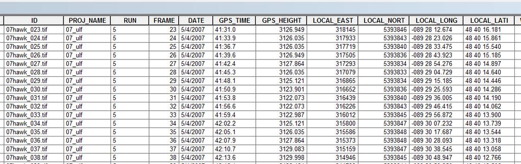
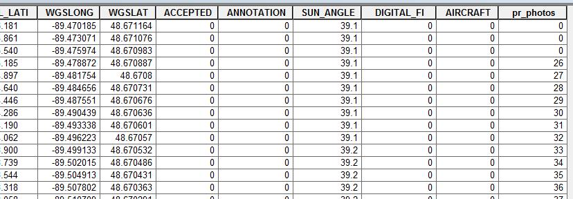
36 En example of an aerial photo flight project and the resulting photo alignment.
37
38 Time, Season, Direction, Weather Aerial photos should be taken when the sun is between 30 and 50 degrees above the horizon. > 30 deg to avoid underexposure due to low illumination and long shadows that obscure the terrain (although, shadows are also desirable when it comes to, e.g., identifying tree species). < 50 deg to avoid so called hotspots unusually bright areas. Photos are almost never taken while the snow is on the ground. Can be taken leaf-on (for easier tree species identification) or leaf-off (for greater visibility of the ground features). Photos can be flown in any direction. Windy and humid days should be avoided to ensure stable flying and to avoid atmospheric scattering of light in humid conditions, respectively.
39 Soft-copy Photogrammetry Contemporary photogrammetry is mainly practiced as soft-copy photogrammetry. Soft-copy means that a digital image is analyzed, not a hard copy image. The first photogrammetric soft-copy system was developed in the early 1980s, by James Case. Soft-copy photogrammetry includes: o Processing of digital aerial imagery o Stereo-viewing of digital aerial imagery o *Measuring above-terrain heights, deriving digital elevation/surface models (DEMs/DSMs) o Producing orthophotos and ortho mosaics o Extracting planimetric features Stereo aerial imagery required. It can be done with individual or stereo imagery, in mono or in stereo. *In certain circumstances above-terrain height measurements can be done in mono imager y as well rarely practised.
40 In order to use photos as true spatial representations of the real-world, geometric relations need to be established between the camera s, photo s and real-world s coordinate systems. Source: Jensen (2007)
41 In stereo photogrammetry geometric relations need to be established between the adjacent photos as well. Source: Wolf (1974)
42 Three aspects are fundamental to (soft-copy) photogrammetry: Interior orientation Exterior orientation Aerial triangulation
43 Interior Orientation The procedure whereby the geometric characteristics of an aerial photograph are mathematically related to the geometric characteristics (including deformities) of the camera system that took the photograph. The relationship is established between the camera internal coordinate system and the image pixel coordinate system. The information on the camera system is usually found in the camera calibration report, created when the camera was produced or recalibrated. Typical information required for interior orientation that is available in the camera calibration report includes: x,y location of the principal point (e.g., x,y = 0,0) x,y location of all fiducial marks (analog cameras) lens focal length lens distortion Radial distortion Tangential distortion (considered negligible) Source: ERDAS (2009)
44 The relation between the geometry of the camera systems and the aerial photograph is calculated and fixed in digital aerial cameras, there are no fiducial marks involved and no need to manually establish this relation. Interior Orientation It is manually established between chemical film-based aerial photos and aerial cameras by using fiducial marks. Fiducial marks are recorded on the chemical film by the camera at the moment of exposure. Source: Jensen (2007)
45 Exterior Orientation Relates image (photo) coordinates to real-world (exterior) map coordinates. Reference real-world points are called Ground Control Points (GCP) and their position is expressed in the X, Y, Z coordinates in a chosen map coordinate system. All aerial photographs are somewhat tilted and this tilt has to be calculated in the model to be able to derive useful measurements from aerial photos. There are six elements of exterior orientation that express the spatial location and angular orientation of a tilted photograph: X L, Y L, Z L the three dimensional coordinates of the aircraft (camera) at the moment of the exposure, expressed in a ground coordinate system. Omega, phi, and kappa (ω, φ, κ) rolling, pitch, and yawning of the camera at the moment of exposure. All the methods developed to determine these six parameters require identification and X, Y, Z coordinates of at least 3 Ground Control Points on the photo. The GCP points need to form a triangle on the photo, they cannot lie in a straight line.
46 Exterior Orientation

47 Exterior Orientation Ideally, GCPs are marked on the ground and precisely measured (e.g. with GPS), but another method of obtaining their location is by using Geographic Information System layers which share identifiable points with the aerial photo (a particular point can be located on both sources). In addition to GCP points, pass (tie) points identifiable on multiple photos and with unknown real-world coordinates can be used as well. Exterior orientation can also be directly derived when GPS and Inertial Measurement Unit (IMU) are onboard (e.g., ADS camera system). IMU is an electronic device that detects changes in pitch, roll and yaw in the aircraft and, by extension, the camera. Source: Jensen (2007)
48 Ground Control Points (GCPs) Preferred configuration of GCPs. If possible there should be at least one GCP on every third image of a block to calculate the exterior orientation parameters for each photo. When working with one photo only, at least three GCPs are needed to calculate the exterior orientation parameters for it. Source: ERDAS (2009)
49 Tie Points A point that can be recognized on multiple overlapping photos but whose ground coordinates are not known before the block triangulation. Ground coordinates for tie points are computed during the block triangulation. Tie points can be determined manually and automatically. Manual determination in block images typically involves nine points in each image.
50 References: ERDAS LPS Project Manager. Viewed March Gehrke, S., Morin, K., Downey, M., Boehrer, N., and Fuchs, T Semi-global matching: An alternative to LIDAR for DSM generation. In Proceedings of the 2010 Canadian Geomatics Conference and Symposium of Commission I. Jensen., J. R Remote Sensing of the Environment: An Earth Resource Perspective. Pearson Prentice Hall. Mikhail M., J. S. Bethel, J. and C. McGlone Introduction to Modern Photogrammetry. John Wiley & Sons. Wolf, P. R Elements of Photogrammetry. McGraw-Hill, Inc.
Photogrammetry: DTM Extraction & Editing
 Photogrammetry: DTM Extraction & Editing How can one determine the x, y, and z of a location? Approaches to DTM Extraction Ground surveying Digitized topographic maps Traditional photogrammetry Hardcopy
Exterior Orientation Parameters
 Exterior Orientation Parameters PERS 12/2001 pp 1321-1332 Karsten Jacobsen, Institute for Photogrammetry and GeoInformation, University of Hannover, Germany The georeference of any photogrammetric product
Chapters 1 7: Overview
 Chapters 1 7: Overview Chapter 1: Introduction Chapters 2 4: Data acquisition Chapters 5 7: Data manipulation Chapter 5: Vertical imagery Chapter 6: Image coordinate measurements and refinements Chapter
Photogrammetry: DTM Extraction & Editing
 Photogrammetry: DTM Extraction & Editing Review of terms Vertical aerial photograph Perspective center Exposure station Fiducial marks Principle point Air base (Exposure Station) Digital Photogrammetry:
Stereoscopic Models and Plotting
 Stereoscopic Models and Plotting Stereoscopic Viewing Stereoscopic viewing is the way the depth perception of the objects through BINOCULAR vision with much greater accuracy. رؤيه البعد الثالث و االحساس
Geometry of Aerial photogrammetry. Panu Srestasathiern, PhD. Researcher Geo-Informatics and Space Technology Development Agency (Public Organization)
") Geometry of Aerial photogrammetry Panu Srestasathiern, PhD. Researcher Geo-Informatics and Space Technology Development Agency (Public Organization) Image formation - Recap The geometry of imaging system
Geometry of Aerial photogrammetry Panu Srestasathiern, PhD. Researcher Geo-Informatics and Space Technology Development Agency (Public Organization) Image formation - Recap The geometry of imaging system
Low-Cost Orthophoto Production Using OrthoMapper Software
 Low-Cost Orthophoto Production Using OrthoMapper Software Rick Day Penn State Cooperative Extension, Geospatial Technology Program, RGIS-Chesapeake Air Photos Historical air photos are available from a
Chapters 1-4: Summary
 Chapters 1-4: Summary So far, we have been investigating the image acquisition process. Chapter 1: General introduction Chapter 2: Radiation source and properties Chapter 3: Radiation interaction with
How tall is Nutting Hall?
 How tall is Nutting Hall? IMAGE DISPLACEMENT on vertical airphotos airphoto (central projection) On a single airphoto topographic-displacement method shadow method On stereo pairs the parallax-height equation
POSITIONING A PIXEL IN A COORDINATE SYSTEM
 GEOREFERENCING AND GEOCODING EARTH OBSERVATION IMAGES GABRIEL PARODI STUDY MATERIAL: PRINCIPLES OF REMOTE SENSING AN INTRODUCTORY TEXTBOOK CHAPTER 6 POSITIONING A PIXEL IN A COORDINATE SYSTEM The essential
Introduction Photogrammetry Photos light Gramma drawing Metron measure Basic Definition The art and science of obtaining reliable measurements by mean
 Photogrammetry Review Neil King King and Associates Testing is an art Introduction Read the question Re-Read Read The question What is being asked Answer what is being asked Be in the know Exercise the
Chapters 1 5. Photogrammetry: Definition, introduction, and applications. Electro-magnetic radiation Optics Film development and digital cameras
 Chapters 1 5 Chapter 1: Photogrammetry: Definition, introduction, and applications Chapters 2 4: Electro-magnetic radiation Optics Film development and digital cameras Chapter 5: Vertical imagery: Definitions,
Measurement of Direction: Bearing vs. Azimuth
 Week 5 Monday Measurement of Direction: Bearing vs. Azimuth Bearing Is an angle of 90 o or less Measured from either North or South in easterly & westerly directions. North 22 o West, South 89 o West,
Training i Course Remote Sensing Basic Theory & Image Processing Methods September 2011
 Training i Course Remote Sensing Basic Theory & Image Processing Methods 19 23 September 2011 Geometric Operations Michiel Damen (September 2011) damen@itc.nl ITC FACULTY OF GEO-INFORMATION SCIENCE AND
TRAINING MATERIAL HOW TO OPTIMIZE ACCURACY WITH CORRELATOR3D
 TRAINING MATERIAL WITH CORRELATOR3D Page2 Contents 1. UNDERSTANDING INPUT DATA REQUIREMENTS... 4 1.1 What is Aerial Triangulation?... 4 1.2 Recommended Flight Configuration... 4 1.3 Data Requirements for
LPS Project Manager User s Guide. November 2009
 LPS Project Manager User s Guide November 2009 Copyright 2009 ERDAS, Inc. All rights reserved. Printed in the United States of America. The information contained in this document is the exclusive property
Chapters 1 9: Overview
 Chapters 1 9: Overview Chapter 1: Introduction Chapters 2 4: Data acquisition Chapters 5 9: Data manipulation Chapter 5: Vertical imagery Chapter 6: Image coordinate measurements and refinements Chapters
MONO-IMAGE INTERSECTION FOR ORTHOIMAGE REVISION
 MONO-IMAGE INTERSECTION FOR ORTHOIMAGE REVISION Mohamed Ibrahim Zahran Associate Professor of Surveying and Photogrammetry Faculty of Engineering at Shoubra, Benha University ABSTRACT This research addresses
LiDAR & Orthophoto Data Report
 LiDAR & Orthophoto Data Report Tofino Flood Plain Mapping Data collected and prepared for: District of Tofino, BC 121 3 rd Street Tofino, BC V0R 2Z0 Eagle Mapping Ltd. #201 2071 Kingsway Ave Port Coquitlam,
TERRESTRIAL AND NUMERICAL PHOTOGRAMMETRY 1. MID -TERM EXAM Question 4
 TERRESTRIAL AND NUMERICAL PHOTOGRAMMETRY 1. MID -TERM EXAM Question 4 23 November 2001 Two-camera stations are located at the ends of a base, which are 191.46m long, measured horizontally. Photographs
TO Ka Yi, Lizzy 6 May
 TO Ka Yi, Lizzy 6 May 2017 1 Contents Basic concepts Practical Issues Examples 2 Data Acquisition Source of Energy Data Products Interpretation & Analysis Digital Propagation through the atmosphere Data
Chapters 1 5. Photogrammetry: Definition, introduction, and applications. Electro-magnetic radiation Optics Film development and digital cameras
 Chapters 1 5 Chapter 1: Photogrammetry: Definition, introduction, and applications Chapters 2 4: Electro-magnetic radiation Optics Film development and digital cameras Chapter 5: Vertical imagery: Definitions,
ArcMap as a quality assurance tool in Photogrammetry Ron Frederiks. Abstract
 ArcMap as a quality assurance tool in Photogrammetry Ron Frederiks Abstract This paper presents the use of ArcMap, 3-D Analyst, Spatial Analyst and Ianko s ETGeoWizards to perform quality assurance of
Extracting Elevation from Air Photos
 Extracting Elevation from Air Photos TUTORIAL A digital elevation model (DEM) is a digital raster surface representing the elevations of a terrain for all spatial ground positions in the image. Traditionally
Chapter 1: Overview. Photogrammetry: Introduction & Applications Photogrammetric tools:
 Chapter 1: Overview Photogrammetry: Introduction & Applications Photogrammetric tools: Rotation matrices Photogrammetric point positioning Photogrammetric bundle adjustment This chapter will cover the
The Applanix Approach to GPS/INS Integration
 Lithopoulos 53 The Applanix Approach to GPS/INS Integration ERIK LITHOPOULOS, Markham ABSTRACT The Position and Orientation System for Direct Georeferencing (POS/DG) is an off-the-shelf integrated GPS/inertial
Geomatica OrthoEngine Orthorectifying VEXCEL UltraCam Data
 Geomatica OrthoEngine Orthorectifying VEXCEL UltraCam Data Vexcel s UltraCam digital camera system has a focal distance of approximately 100mm and offers a base panchromatic (black and white) resolution
Calibration of IRS-1C PAN-camera
 Calibration of IRS-1C PAN-camera Karsten Jacobsen Institute for Photogrammetry and Engineering Surveys University of Hannover Germany Tel 0049 511 762 2485 Fax -2483 Email karsten@ipi.uni-hannover.de 1.
ifp Universität Stuttgart Performance of IGI AEROcontrol-IId GPS/Inertial System Final Report
 Universität Stuttgart Performance of IGI AEROcontrol-IId GPS/Inertial System Final Report Institute for Photogrammetry (ifp) University of Stuttgart ifp Geschwister-Scholl-Str. 24 D M. Cramer: Final report
DETERMINATION OF IMAGE ORIENTATION SUPPORTED BY IMU AND GPS
 DETERMINATION OF IMAGE ORIENTATION SUPPORTED BY IMU AND GPS Karsten Jacobsen University of Hannover Institute for Photogrammetry and Engineering Surveys Nienburger Str. 1 D-30167 Hannover Jacobsen@ipi.uni-hannover.de
COORDINATE TRANSFORMATION. Lecture 6
 COORDINATE TRANSFORMATION Lecture 6 SGU 1053 SURVEY COMPUTATION 1 Introduction Geomatic professional are mostly confronted in their work with transformations from one two/three-dimensional coordinate system
PHOTOGRAMMETRIC PROCESSING OF LOW ALTITUDE IMAGE SEQUENCES BY UNMANNED AIRSHIP
 PHOTOGRAMMETRIC PROCESSING OF LOW ALTITUDE IMAGE SEQUENCES BY UNMANNED AIRSHIP Yongjun Zhang School of Remote Sensing and Information Engineering, Wuhan University, Wuhan, Hubei, 430079, P.R. China - zhangyj@whu.edu.cn
THE INTERIOR AND EXTERIOR CALIBRATION FOR ULTRACAM D
 THE INTERIOR AND EXTERIOR CALIBRATION FOR ULTRACAM D K. S. Qtaishat, M. J. Smith, D. W. G. Park Civil and Environment Engineering Department, Mu ta, University, Mu ta, Karak, Jordan, 61710 khaldoun_q@hotamil.com
Course Outline (1) #6 Data Acquisition for Built Environment. Fumio YAMAZAKI
 #6 Data Acquisition for Built Environment. Fumio YAMAZAKI") AT09.98 Applied GIS and Remote Sensing for Disaster Mitigation #6 Data Acquisition for Built Environment 9 October, 2002 Fumio YAMAZAKI yamazaki@ait.ac.th http://www.star.ait.ac.th/~yamazaki/ Course Outline
AT09.98 Applied GIS and Remote Sensing for Disaster Mitigation #6 Data Acquisition for Built Environment 9 October, 2002 Fumio YAMAZAKI yamazaki@ait.ac.th http://www.star.ait.ac.th/~yamazaki/ Course Outline
Phototriangulation Introduction
 Introduction Photogrammetry aims to the reconstruction of the 3D object-space from the 2D image-space, thus leading to the computation of reliable, indirect measurements of 3D coordinates in the object-space
ACCURACY ANALYSIS FOR NEW CLOSE-RANGE PHOTOGRAMMETRIC SYSTEMS
 ACCURACY ANALYSIS FOR NEW CLOSE-RANGE PHOTOGRAMMETRIC SYSTEMS Dr. Mahmoud El-Nokrashy O. ALI Prof. of Photogrammetry, Civil Eng. Al Azhar University, Cairo, Egypt m_ali@starnet.com.eg Dr. Mohamed Ashraf
Using ArcGIS Server Data to Assist in Planimetric Update Process. Jim Stout - IMAGIS Rick Hammond Woolpert
 Using ArcGIS Server Data to Assist in Planimetric Update Process Jim Stout - IMAGIS Rick Hammond Woolpert Using ArcGIS Server Data to Assist in Planimetric Update Process Jim Stout - IMAGIS Rick Hammond
ADS40 Calibration & Verification Process. Udo Tempelmann*, Ludger Hinsken**, Utz Recke*
 ADS40 Calibration & Verification Process Udo Tempelmann*, Ludger Hinsken**, Utz Recke* *Leica Geosystems GIS & Mapping GmbH, Switzerland **Ludger Hinsken, Author of ORIMA, Konstanz, Germany Keywords: ADS40,
COMBINED BUNDLE BLOCK ADJUSTMENT VERSUS DIRECT SENSOR ORIENTATION ABSTRACT
 COMBINED BUNDLE BLOCK ADJUSTMENT VERSUS DIRECT SENSOR ORIENTATION Karsten Jacobsen Institute for Photogrammetry and Engineering Surveys University of Hannover Nienburger Str.1 D-30167 Hannover, Germany
Iowa Department of Transportation Office of Design. Photogrammetric Mapping Specifications
 Iowa Department of Transportation Office of Design Photogrammetric Mapping Specifications March 2015 1 Purpose of Manual These Specifications for Photogrammetric Mapping define the standards and general
Geometric Rectification of Remote Sensing Images
 Geometric Rectification of Remote Sensing Images Airborne TerrestriaL Applications Sensor (ATLAS) Nine flight paths were recorded over the city of Providence. 1 True color ATLAS image (bands 4, 2, 1 in
Trimble Engineering & Construction Group, 5475 Kellenburger Road, Dayton, OH , USA
 Trimble VISION Ken Joyce Martin Koehler Michael Vogel Trimble Engineering and Construction Group Westminster, Colorado, USA April 2012 Trimble Engineering & Construction Group, 5475 Kellenburger Road,
Orthophotography and LiDAR Terrain Data Collection Rogue River, Oregon Final Report
 Orthophotography and LiDAR Terrain Data Collection Rogue River, Oregon Final Report Prepared by Sky Research, Inc. 445 Dead Indian Memorial Road Ashland, OR 97520 Prepared for Rogue Valley Council of Governments
PHOTOGRAMMETRIC SOLUTIONS OF NON-STANDARD PHOTOGRAMMETRIC BLOCKS INTRODUCTION
 PHOTOGRAMMETRIC SOLUTIONS OF NON-STANDARD PHOTOGRAMMETRIC BLOCKS Dor Yalon Co-Founder & CTO Icaros, Inc. ABSTRACT The use of small and medium format sensors for traditional photogrammetry presents a number
Light Detection and Ranging (LiDAR)
") Light Detection and Ranging (LiDAR) http://code.google.com/creative/radiohead/ Types of aerial sensors passive active 1 Active sensors for mapping terrain Radar transmits microwaves in pulses determines
Light Detection and Ranging (LiDAR) http://code.google.com/creative/radiohead/ Types of aerial sensors passive active 1 Active sensors for mapping terrain Radar transmits microwaves in pulses determines
BUNDLE BLOCK ADJUSTMENT WITH HIGH RESOLUTION ULTRACAMD IMAGES
 BUNDLE BLOCK ADJUSTMENT WITH HIGH RESOLUTION ULTRACAMD IMAGES I. Baz*, G. Buyuksalih*, K. Jacobsen** * BIMTAS, Tophanelioglu Cad. ISKI Hizmet Binasi No:62 K.3-4 34460 Altunizade-Istanbul, Turkey gb@bimtas.com.tr
Leica Systems Overview
 RC30 AERIAL CAMERA SYSTEM Leica Systems Overview The Leica RC30 aerial film camera is the culmination of decades of development, started with Wild's first aerial camera in the 1920s. Beautifully engineered
CORRECTING RS SYSTEM DETECTOR ERROR GEOMETRIC CORRECTION
 1 CORRECTING RS SYSTEM DETECTOR ERROR GEOMETRIC CORRECTION Lecture 1 Correcting Remote Sensing 2 System Detector Error Ideally, the radiance recorded by a remote sensing system in various bands is an accurate
Map Compilation CHAPTER HISTORY
 CHAPTER 7 Map Compilation 7.1 HISTORY Producing accurate commercial maps from aerial photography began in the 1930s. The technology of stereomapping over the last 70 years has brought vast technological
A NEW APPROACH FOR GENERATING A MEASURABLE SEAMLESS STEREO MODEL BASED ON MOSAIC ORTHOIMAGE AND STEREOMATE
 A NEW APPROACH FOR GENERATING A MEASURABLE SEAMLESS STEREO MODEL BASED ON MOSAIC ORTHOIMAGE AND STEREOMATE Mi Wang State Key Laboratory of Information Engineering in Surveying Mapping and Remote Sensing
Technical Considerations and Best Practices in Imagery and LiDAR Project Procurement
 Technical Considerations and Best Practices in Imagery and LiDAR Project Procurement Presented to the 2014 WV GIS Conference By Brad Arshat, CP, EIT Date: June 4, 2014 Project Accuracy A critical decision
SimActive and PhaseOne Workflow case study. By François Riendeau and Dr. Yuri Raizman Revision 1.0
 SimActive and PhaseOne Workflow case study By François Riendeau and Dr. Yuri Raizman Revision 1.0 Contents 1. Introduction... 2 1.1. Simactive... 2 1.2. PhaseOne Industrial... 2 2. Testing Procedure...
STARTING WITH DRONES. Data Collection and Remote Sensing with UAVs, etc. Dr. Bill Hazelton LS
 STARTING WITH DRONES Data Collection and Remote Sensing with UAVs, etc. Dr. Bill Hazelton LS What this Talk is About UAV-based data acquisition: What you need to get involved Processes in getting spatial
Tutorial (Beginner level): Orthomosaic and DEM Generation with Agisoft PhotoScan Pro 1.3 (with Ground Control Points)
: Orthomosaic and DEM Generation with Agisoft PhotoScan Pro 1.3 (with Ground Control Points)") Tutorial (Beginner level): Orthomosaic and DEM Generation with Agisoft PhotoScan Pro 1.3 (with Ground Control Points) Overview Agisoft PhotoScan Professional allows to generate georeferenced dense point
Tutorial (Beginner level): Orthomosaic and DEM Generation with Agisoft PhotoScan Pro 1.3 (with Ground Control Points) Overview Agisoft PhotoScan Professional allows to generate georeferenced dense point
DEVELOPMENT OF CAMERA MODEL AND GEOMETRIC CALIBRATION/VALIDATION OF XSAT IRIS IMAGERY
 DEVELOPMENT OF CAMERA MODEL AND GEOMETRIC CALIBRATION/VALIDATION OF XSAT IRIS IMAGERY Leong Keong Kwoh, Xiaojing Huang, Wee Juan Tan Centre for Remote, Imaging Sensing and Processing (CRISP), National
Sasanka Madawalagama Geoinformatics Center Asian Institute of Technology Thailand
 Sasanka Madawalagama Geoinformatics Center Asian Institute of Technology Thailand This learning material was not prepared by ADB. The views expressed in this document are the views of the author/s and
Multi-Image Geo Location and 3D Feature Extraction from Stereo. Gene Rose
 Multi-Image Geo Location and 3D Feature Extraction from Stereo Gene Rose Introduction In RemoteView, both basic and advanced Photogrammetric processes are available. The white paper titled Basic Photogrammetry
Stereo CSE 576. Ali Farhadi. Several slides from Larry Zitnick and Steve Seitz
 Stereo CSE 576 Ali Farhadi Several slides from Larry Zitnick and Steve Seitz Why do we perceive depth? What do humans use as depth cues? Motion Convergence When watching an object close to us, our eyes
PLS - EXAMINATION PREPARATION PHOTOGRAMMETRY 101. A paper on the principles of photogrammetric mapping
 Photogrammetric Consultants PLS - EXAMINATION PREPARATION PHOTOGRAMMETRY 101 A paper on the principles of photogrammetric mapping Photogrammetry is the art and science of obtaining reliable measurements
3D DIGITAL MODELING OF MODERN TIMES BUILDING FOR PRESERVATION AND RESTORATION
 3D DIGITAL MODELING OF MODERN TIMES BUILDING FOR PRESERVATION AND RESTORATION W.J. Oh a *, S.H. Han b, H.C. Yoon c, Y.S. Bae d, S.H. Song e a Dept. of Land Information Management, ChungCheong University,
Characterizing Strategies of Fixing Full Scale Models in Construction Photogrammetric Surveying. Ryan Hough and Fei Dai
 697 Characterizing Strategies of Fixing Full Scale Models in Construction Photogrammetric Surveying Ryan Hough and Fei Dai West Virginia University, Department of Civil and Environmental Engineering, P.O.
CHAPTER 10. Digital Mapping and Earthwork
 CHAPTER 10 Digital Mapping and Earthwork www.terrainmap.com/rm22.html CE 316 March 2012 348 10.1 Introduction 349 10.2 Single Images 10.2.1 Rectified Photograph With a single photograph, X,Y data can be
GEOMETRIC POTENTIAL OF IRS-1 C PAN-CAMERA. Jacobsen, Karsten University of Hannover
 GEOMETRIC POTENTIAL OF IRS-1 C PAN-CAMERA Jacobsen, Karsten University of Hannover Email: karsten@ipi.uni-hannover.de KEY WORDS: Geometry, IRS1-C, block adjustment ABSTRACT: IRS-1 C images with optimal
ALS40 Airborne Laser Scanner
 ALS40 Airborne Laser Scanner Airborne LIDAR for Professionals High Performance Laser Scanning Direct Measurement of Ground Surface from the Air The ALS40 Airborne Laser Scanner measures the topography
GE 119 PHOTOGRAMMETRY 2
 GE 119 PHOTOGRAMMETRY 2 Topic 3. Principles of Stereophotogrammetry Instructor: Engr. Jojene R. Santillan jrsantillan@carsu.edu.ph santillan.jr3@gmail.com Division of Geodetic Engineering College of Engineering
Tutorial (Beginner level): Orthomosaic and DEM Generation with Agisoft PhotoScan Pro 1.3 (without Ground Control Points)
: Orthomosaic and DEM Generation with Agisoft PhotoScan Pro 1.3 (without Ground Control Points)") Tutorial (Beginner level): Orthomosaic and DEM Generation with Agisoft PhotoScan Pro 1.3 (without Ground Control Points) Overview Agisoft PhotoScan Professional allows to generate georeferenced dense point
Tutorial (Beginner level): Orthomosaic and DEM Generation with Agisoft PhotoScan Pro 1.3 (without Ground Control Points) Overview Agisoft PhotoScan Professional allows to generate georeferenced dense point
Geometric Accuracy Evaluation, DEM Generation and Validation for SPOT-5 Level 1B Stereo Scene
 Geometric Accuracy Evaluation, DEM Generation and Validation for SPOT-5 Level 1B Stereo Scene Buyuksalih, G.*, Oruc, M.*, Topan, H.*,.*, Jacobsen, K.** * Karaelmas University Zonguldak, Turkey **University
Accuracy Assessment of POS AVX 210 integrated with the Phase One ixu150
 White Paper 3/17/2016 Accuracy Assessment of POS AVX 210 integrated with the Phase One ixu150 Omer Mian, Joe Hutton, Greg Lipa, James Lutes, Damir Gumerov, Srdjan Sobol Applanix, William Chan - GeoPixel
Digital Photogrammetric System. Version 6.3 USER MANUAL. Aerial triangulation
 Digital Photogrammetric System Version 6.3 USER MANUAL Table of Contents 1. Purpose of the document... 5 2. data... 5 2.1. The Orientation menu... 5 2.2. Source data... 7 2.3. workflow... 8 2.4. Data quality
Creating an Event Theme from X, Y Data
 Creating an Event Theme from X, Y Data In Universal Transverse Mercator (UTM) Coordinates Eastings (measured in meters) typically have 6 digits left of the decimal. Northings (also in meters) typically
APPLICATION AND ACCURACY EVALUATION OF LEICA ADS40 FOR LARGE SCALE MAPPING
 APPLICATION AND ACCURACY EVALUATION OF LEICA ADS40 FOR LARGE SCALE MAPPING WenYuan Hu a, GengYin Yang b, Hui Yuan c,* a, b ShanXi Provincial Survey and Mapping Bureau, China - sxgcchy@public.ty.sx.cn c
EVOLUTION OF POINT CLOUD
 Figure 1: Left and right images of a stereo pair and the disparity map (right) showing the differences of each pixel in the right and left image. (source: https://stackoverflow.com/questions/17607312/difference-between-disparity-map-and-disparity-image-in-stereo-matching)
DIGITAL SURFACE MODELS OF CITY AREAS BY VERY HIGH RESOLUTION SPACE IMAGERY
 DIGITAL SURFACE MODELS OF CITY AREAS BY VERY HIGH RESOLUTION SPACE IMAGERY Jacobsen, K. University of Hannover, Institute of Photogrammetry and Geoinformation, Nienburger Str.1, D30167 Hannover phone +49
Leica Photogrammetry Suite Automatic Terrain Extraction
 Leica Photogrammetry Suite Automatic Terrain Extraction Copyright 2006 Leica Geosystems Geospatial Imaging, LLC All rights reserved. Printed in the United States of America. The information contained in
Photogrammetry: A Modern Tool for Crash Scene Mapping
 Photogrammetry: A Modern Tool for Crash Scene Mapping Background A police accident investigator (AI) has many tasks when arriving at a crash scene. The officer s highest priority is public safety; the
MODEL DEFORMATION ACCURACY OF DIGITAL FRAME CAMERAS
 MODEL DEFORMATION ACCURACY OF DIGITAL FRAME CAMERAS V. Spreckels a, A. Schlienkamp a, K. Jacobsen b a Deutsche Steinkohle AG (DSK), Dept. Geoinformation/Engineering Survey BG G, Shamrockring 1, D-44623
Overview. Image Geometric Correction. LA502 Special Studies Remote Sensing. Why Geometric Correction?
 LA502 Special Studies Remote Sensing Image Geometric Correction Department of Landscape Architecture Faculty of Environmental Design King AbdulAziz University Room 103 Overview Image rectification Geometric
Lecture 11. LiDAR, RADAR
 NRMT 2270, Photogrammetry/Remote Sensing Lecture 11 Calculating the Number of Photos and Flight Lines in a Photo Project LiDAR, RADAR Tomislav Sapic GIS Technologist Faculty of Natural Resources Management
Absolute Horizontal Accuracies of Pictometry s Individual Orthogonal Frame Imagery
 A Pictometry International, Corp White Paper Absolute Horizontal Accuracies of Pictometry s Individual Orthogonal Frame Imagery Michael J. Zoltek VP, Surveying & Mapping Pictometry International, Corp
Terrestrial GPS setup Fundamentals of Airborne LiDAR Systems, Collection and Calibration. JAMIE YOUNG Senior Manager LiDAR Solutions
 Terrestrial GPS setup Fundamentals of Airborne LiDAR Systems, Collection and Calibration JAMIE YOUNG Senior Manager LiDAR Solutions Topics Terrestrial GPS reference Planning and Collection Considerations
REMOTE SENSING LiDAR & PHOTOGRAMMETRY 19 May 2017
 REMOTE SENSING LiDAR & PHOTOGRAMMETRY 19 May 2017 SERVICES Visual Inspections Digital Terrain Models Aerial Imagery Volume Computations Thermal Inspections Photo maps Aerial Video Training & Consultancy
AN INTEGRATED SENSOR ORIENTATION SYSTEM FOR AIRBORNE PHOTOGRAMMETRIC APPLICATIONS
 AN INTEGRATED SENSOR ORIENTATION SYSTEM FOR AIRBORNE PHOTOGRAMMETRIC APPLICATIONS M. J. Smith a, *, N. Kokkas a, D.W.G. Park b a Faculty of Engineering, The University of Nottingham, Innovation Park, Triumph
GUIDELINES FOR THE IN SITU GEOMETRIC CALIBRATION OF THE AERIAL CAMERA SYSTEM
 GUIDELINES FOR THE IN SITU GEOMETRIC CALIBRATION OF THE AERIAL CAMERA SYSTEM These guidelines have been developed by the Primary Data Acquisition Division and the Camera Calibration Committee, and have
GMAT9300 Aerial and Satellite Imaging Systems
 GMAT9300 Aerial and Satellite Imaging Systems Semester 2, 2016 COURSE DETAILS Units of Credit 6 Contact hours 5 Class Mon 10.00 to 13.00 BUS130 Workshop Tuesday 15.00 to 17.00 QUAD047 and CivEng Lab 201
Digital Photogrammetric System. Version 5.3 USER GUIDE. Processing of UAV data
 Digital Photogrammetric System Version 5.3 USER GUIDE Table of Contents 1. Workflow of UAV data processing in the system... 3 2. Create project... 3 3. Block forming... 5 4. Interior orientation... 6 5.
Terrain correction. Backward geocoding. Terrain correction and ortho-rectification. Why geometric terrain correction? Rüdiger Gens
 Terrain correction and ortho-rectification Terrain correction Rüdiger Gens Why geometric terrain correction? Backward geocoding remove effects of side looking geometry of SAR images necessary step to allow
INVESTIGATION OF 1:1,000 SCALE MAP GENERATION BY STEREO PLOTTING USING UAV IMAGES
 INVESTIGATION OF 1:1,000 SCALE MAP GENERATION BY STEREO PLOTTING USING UAV IMAGES S. Rhee a, T. Kim b * a 3DLabs Co. Ltd., 100 Inharo, Namgu, Incheon, Korea ahmkun@3dlabs.co.kr b Dept. of Geoinformatic
GEO-REFERENCING CASI IMAGERY USING DIRECT MEASUREMENT OF POSITION AND ATTITUDE
 GEO-REFERENCING CASI IMAGERY USING DIRECT MEASUREMENT OF POSITION AND ATTITUDE Rakesh K. SHUKLA *, Martin J. SMITH Institute of Engineering Surveying and Space Geodesy The University of Nottingham University
PART A Three-Dimensional Measurement with iwitness
 PART A Three-Dimensional Measurement with iwitness A1. The Basic Process The iwitness software system enables a user to convert two-dimensional (2D) coordinate (x,y) information of feature points on an
Geometric Correction
 CEE 6150: Digital Image Processing Geometric Correction 1 Sources of Distortion Sensor Characteristics optical distortion aspect ratio non-linear mirror velocity detector geometry & scanning sequence Viewing
The Accuracy of Determining the Volumes Using Close Range Photogrammetry
 IOSR Journal of Mechanical and Civil Engineering (IOSR-JMCE) e-issn: 2278-1684,p-ISSN: 2320-334X, Volume 12, Issue 2 Ver. VII (Mar - Apr. 2015), PP 10-15 www.iosrjournals.org The Accuracy of Determining
(Subsea) Keith Vickery Zupt LLC
 Keith Vickery Zupt LLC") (Subsea) Keith Vickery Zupt LLC kv@zupt.com Offshore subsea infrastructure surveys (pipeline inspection, well, XT, and manifold inspections) are required to ensure compliance with both internal operator,
(Subsea) Keith Vickery Zupt LLC kv@zupt.com Offshore subsea infrastructure surveys (pipeline inspection, well, XT, and manifold inspections) are required to ensure compliance with both internal operator,
CALIBRATION ASPECTS IN DIRECT GEOREFERENCING OF FRAME IMAGERY
 CALIBRATION ASPECTS IN DIRECT GEOREFERENCING OF FRAME IMAGERY Karsten Jacobsen University of Hannover Institute for Photogrammetry and GeoInformation Nienburger Str. 1 D-30167 Hannover, Germany jacobsen@ipi.uni-hannover.de
University of Technology Building & Construction Department / Remote Sensing & GIS lecture
 5. Corrections 5.1 Introduction 5.2 Radiometric Correction 5.3 Geometric corrections 5.3.1 Systematic distortions 5.3.2 Nonsystematic distortions 5.4 Image Rectification 5.5 Ground Control Points (GCPs)
CONSISTENT COLOR RESAMPLE IN DIGITAL ORTHOPHOTO PRODUCTION INTRODUCTION
 CONSISTENT COLOR RESAMPLE IN DIGITAL ORTHOPHOTO PRODUCTION Yaron Katzil 1, Yerach Doytsher 2 Mapping and Geo-Information Engineering Faculty of Civil and Environmental Engineering Technion - Israel Institute
Laser sensors. Transmitter. Receiver. Basilio Bona ROBOTICA 03CFIOR
 Mobile & Service Robotics Sensors for Robotics 3 Laser sensors Rays are transmitted and received coaxially The target is illuminated by collimated rays The receiver measures the time of flight (back and
LIDAR MAPPING FACT SHEET
 1. LIDAR THEORY What is lidar? Lidar is an acronym for light detection and ranging. In the mapping industry, this term is used to describe an airborne laser profiling system that produces location and
GIS Data Collection. This chapter reviews the main methods of GIS data capture and transfer and introduces key practical management issues.
 9 GIS Data Collection OVERVIEW This chapter reviews the main methods of GIS data capture and transfer and introduces key practical management issues. It distinguishes between primary (direct measurement)
Basic Principles of Photogrammetry
 Basic Principles of Photogrammetry Annual Conference of PSLS January 13 16, 2019 Hershey, PA Frank Derby, PhD Penn State University Lehman, PA 18627 Workshop Content General Principles of Photogrammetry
Some Aspects On Developing a Truly Low-Cost Mapping System Using Handheld GPS and Camcorder
 Some Aspects On Developing a Truly Low-Cost Mapping System Using Handheld GPS and Camcorder ABSTRACT There are some characteristics for the mapping systems that need to be developing which are low-cost,