Introduction Photogrammetry Photos light Gramma drawing Metron measure Basic Definition The art and science of obtaining reliable measurements by mean
|
|
|
- Victor Kelley
- 6 years ago
- Views:
Transcription

1 Photogrammetry Review Neil King King and Associates Testing is an art Introduction Read the question Re-Read Read The question What is being asked Answer what is being asked Be in the know Exercise the art of Visualization Accept the Suggestion of Passing 1
2 Introduction Photogrammetry Photos light Gramma drawing Metron measure Basic Definition The art and science of obtaining reliable measurements by means of photographs. Introduction American Society for Photogrammetry and Remote Sensing, ASPRS Refined Definition The art, science, and technology of obtaining reliable information about physical objects and the environment through the processes of recording, measuring and interpreting photographic images and patterns of electromagnetic radiant energy and other phenomena." 2

3 Introduction Electro Magnetic Spectrum Gamma Rays to Radio Waves Invisible to Visible Defines our world as we see it Utilized by Photogrammetric Sensors Unlimited Possibilities Introduction Sensors and the Electro Magnetic Spectrum Sensors detect physical information Converted to electrical signals Translated to angles, distances, reflectance, etc Tied to Arbitrary and Local reference frames Developed into models Decision Analysis Geomatics 3
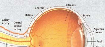
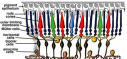
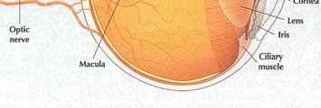
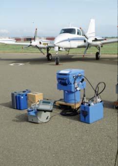
4 Introduction Human Vision an Amazing Sensor Introduction Photogrammetric Technology 4


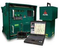
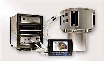
5 Introduction Photogrammetric Future UAV + Sensor Combination & Fusion Introduction Photogrammetic Range Aerial Photography Photogrammetry / Digital Mapping Digital Orthophotography LiDAR Mapping Mobile Mapping Remote Sensing 5
6 Photogrammetric Production Aerial, LiDAR, Hyperspectral etc. Data Acquisition Scan Films Analog QC Digital Project Monitorin ng & Quality Review Create New DTMS AutoCorrelation QC Orthorectification Orthophotos QC AeroTriangulation QC Stereo Compilation l SuperImposition Map Edit QC Ground Survey Airborne GPS Support Vectors Remote Sensing Data GIS/LIS Data Classification Scale C-Factor Relief Displacement Scale Choice Geometric Key Concepts S = f / H Cf = H / CI h = d * H / r 2, d = r 2 r 1 Horizontal vs Vertical Requirements Scale map = Scale photo / Enlargement Scale map = f / CI * C-factor End Lap Gain S * L * [( 100 End Lap % ) / 100] Side Lap Gain S * W * [( 100 Side Lap % ) / 100] Min Number of Models ( Length / End Gain ) round up Min Photos per flight Line ( Length / End Gain ) round up + 1 Min Number of flight Lines ( Width / Side Lap Gain ) round Ground Control Vert = 3+1 Horiz = 2+1 Target Size W= ps*0.002, Legs = 12*W 6
7 Geometry of Aerial Photographs Photogrammetric Photography Frame Metric Cameras Vertical Photography Image Plane Parallel to the Ground, Nearly Optical Axis Perpendicular to the Ground Contains 3D Information Perspective based All Light Rays converge at the lens Weakest measurement along the optical axis Heights require rigid constraints Overlapping Photography Stereoscopic Coverage ( end lap, side lap ) Geometry of Aerial Photographs Frame Metric Cameras Analog Film Based Standard Frame size 9 by 9 Focal Length 6,154mm / 12,305mm Calibration Report ( date range ) Digital CCD based, Concept of Pixels Variable frame Size 14430,9420 / 13824,7680 Variable focal length 100mm / 120mm Calibration Report ( date range ) 7
8 Geometry of Aerial Photographs Scale Expression Representative Fraction Ratio One unit = a similar number of same units 1 inches = 100 inches or 1:100 Map Or Engineers Scale Ratio One unit = a similar number of different units 1 inch = 100 feet Geometry of Aerial Photographs Scale Small Vs Large Smaller Scales Cover larger areas 1:24,000 or 1 inch = 2,000 ft Larger Scales Cover smaller areas 1:1,200 or 1 inch = 100 ft 8


9 Geometry of Aerial Photographs Scale Maps vs. Aerial Maps Scale is constant No relief displacement Orthographic or Planimetric Projection Aerial Photos Scale varies Topographical Relief displacement is present Aerial photos have nominal scale Varies with Topographical Relief Perspective Projection Geometry of Aerial Photographs Geometry of Photographic Scale Geometry of Similar triangles 9
10 Geometry of Aerial Photographs Photographic Over Lap Forward Over Lap Over Lap between Photographs along the Flight Line Provides Stereoscopic Coverage 3D Viewing and measuring Provides small over lap between alternate photographs for extending control through the Analytical of process AeroTriangulation Side Lap Side lap Between the Flight Lines Allows extending control to successive flight lines through the Analytical process of AeroTriangulation Geometry of Aerial Photographs Photographic Gain End Lap Gain Principle Point to Principle Point Scale * Length * [ ( 100 End Lap % ) / 100 ] 9 inch Width and 60 % end lap Scale Photo * 3.6 in Side Lap Gain Distance between Flight Lines Scale * Width * [ ( 100 Side Lap % ) / 100 ] 9 inch Width and 30 % end lap Scale Photo * 6.3 in 10

11 Geometry of Aerial Photographs End Lap Gain Geometry of Aerial Photographs Side Lap Gain 11

12 Geometry of Aerial Photographs Neat Model The stereoscopic area between adjacent principle points, ( Exposure Stations ), and extended out sideways in both directions to middle of the side laps If no side laps exist, one can extend to no more then 1 from the extents of the dimension of the Frame on either side Geometry of Aerial Photographs Neat Model 12
13 Geometry of Aerial Photographs Relief Displacement The radial distance between where an object appears in an image to where it actually appears on the Datum, ( ground ) Causes Camera Tilt and Earth Curvature Minor Topographic Terrain Relief or Elevation Differences Major Displacement is a radial distance outwards for elevations above the Datum Displacement is a radial distance inwards for elevations below the Datum The nadir point on the datum, opposite the principle point, (Exposure Station), is always free of any relief displacement. Geometry of Aerial Photographs Relief Displacement 13
14 Geometry of Aerial Photographs Object Heights and Relief Displacement h = Δr r * H / r 2 h = height of object r 1 = radial distance from the principle point to base of an image object r 2 = radial distance from the principle point to top of an image object H = flying height Δr r = r 2 r 1 Proportionality Geometry of Aerial Photographs Object Heights and Relief Displacement 14
15 Geometry of Aerial Photographs Object Heights and Relief Displacement h = Δr r * H / r 2, Δr r = r 2 r 1 ( Proportionality ) Camera Coordinate System Geometry of Aerial Photographs C-factor Is an empirical value that defines the ability to accurately measure the vertical component in a stereo model using a given type of photogrammetric instrumentation. Vertical measurements depend not only on the photogrammetric instrumentation, but also upon the nature of the terrain, the camera and its calibration, the resolution quality of the photography, the density and accuracy of the ground control 15
16 Geometry of Aerial Photographs C-Factor is Based Upon Photographic Geometry Focal Length of the Frame Camera ( f ) Flying Height ( H ) Air Base ( b ) Distance between exposures Key: Air Base to Flying Height Ratio ( b / H) Image Measurement Accuracy at photo scale The ability to discriminate increments of error in elevation The measurement of Parallax Geometry of Aerial Photographs C-factor Mathematical Formulation Flying Height = Contour Interval * C-factor 16
17 Photogrammetric Plotters StereoPlotters Softcopy Fifth Generation All digital environment on computer C-Factor=2000, resolution = 3-5 µms, Enlargement 7x Analytical Fourth Generation Optical and Computer environment Diapositives C-Factor=2000 Factor=2000, resolution = 3-5 µms, Enlargement 7x Analog Third Generation Optical, Scribing and Computer environment Diapositives C-Factor=1600, resolution = µms, Enlargement 6x Photogrammetric Plotters Stereoscopic Parallax The displacement of an object caused by a change in the point of observation is called parallax. Stereoscopic parallax is created by overlapping aerial photographs of the same object from different points of observation. Overlapping aerial photos are referred to as stereopairs and can be used to measure object height. Stereopairs are utilized to interpret objects, locate objects and determine object heights. They contain Y and X Parallax. 17


18 Photogrammetric Plotters Stereoscopic Y Parallax (Relative Orientation) Difference in perpendicular distances between two image of a point from the vertical Y-Parallax due to tilt Y-Parallax due to variation of heights Y-Parallax due to miss-alignment Photogrammetric Plotters Stereoscopic X Parallax (measurements) The Difference in the position of observation of a point as seen in two over lapping photographs, or stereopair 18
19 Photo Scale Selection Horizontal Requirements Photographic Enlargement Factors Stereoplotter tt based Scale map = Scale photo / Enlargement Factor Vertical Requirements Specified by Contour Interval Use C-factor to find Flying Height Scale map = focal Length / Contour Interval * C-factor Select the larger of the two derived scales Models and Flight Lines Min Number of Models (Project Length / End Lap Gain ) rounded up Min Photos per flight Line (Project Length / End Lap Gain ) rounded up + 1 photo Min Number of flight Lines ( Project Width / Side Lap Gain ) rounded up 19
20 Ground control Vertical - Leveling the model Minimum of 3 Vertical points 1 more as a check ( Redundancy ) Horizontal - Scaling the model Minimum of Horizontal 2 points 1 more as a check ( Redundancy ) Minimum to Control a Model 3 points vertical and Horizontal 1 more as a check ( Redundancy ) Ground Control A Single Model In Practice 4 points vertical and Horizontal ontal At or near the corners 1 as a check in the middle For Blocks In General 1 vertical every 2 models edges 1 Horizontial every 4 models edges Supplamental Vertical on the interior 20
21 OrthoPhotos Image that is corrected for Camera Tilt & Terrain Relief ( Orthographic? ) Digital Image Requires a digital Image, interior and exterior orientation parameters and a digital elevation surface Rectification The process of removing camera tilt and terrain relief. The process of mathematically re-sampling the input image to the digital elevation surface The process of creating an orthographic projection of the image based upon the digital elevation surface The process of georeferencing Digital Image OrthoPhotos Rectangular a file of rows and column Composed of DN values or Grey scale values, pixels Origin most commonly is the Upper left hand corner Pixels have spatial resolution Native resolution or scan resolution (a x b) Ground resolution (A g x B g ) Scale = image distance / ground distance 21
 used to record the illumination level of a pixel 8-bit data = 256 density levels")

22 Digital Images OrthoPhotos Pixels have radiometric resolution The number of bits (binary digits) used to record the illumination level of a pixel 8-bit data = 256 density levels 16-bit data = 65,536 density levels Pixels have Spectral resolution The range of distinguishable EMR wavelengths Black and white Red, Green, Blue Infrared Digital Image Pixel Resolution OrthoPhotos 22
23 Digital Image Georeferencing OrthoPhotos A geographic reference frame World files tfw, jpw, bpw, etc Affine Transformation Line 1: A: : x component of the pixel width (x-scale) Line 2: D: : y component of the pixel width (y-skew) Line 3: B: : x component of the pixel height (x-skew) Line 4: E: : y component of the pixel height (y-scale), almost always negative Line 5: C: x-coordinate center of the upper left pixel Line 6: F: y-coordinate center of the upper left pixel Geotiffs more information Target Size Tied to photo scale Aerial Target Size Traditionally Width of the Target Legs W = Photo scale * Length of the Target Legs 5 * W 23
 / 100] Side Lap Gain S * W * [( 100 Side Lap % ) / 100]")
 round up Ground Control Vert = 3+1, Horiz = 2+1, MDL = 3 + 1 Target Size W= ps*0.")
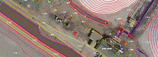
24 Scale C-Factor Relief Displacement Scale Choice Review S = f / H Cf = H / CI h = d * H / r 2, d = r 2 r 1 Horizontal vs Vertical Requirements Scale map = Scale photo / Enlargement Scale map = f / CI * C-factor End Lap Gain S * L * [( 100 End Lap % ) / 100] Side Lap Gain S * W * [( 100 Side Lap % ) / 100] Min Number of Models (Length / End Gain ) round up Min Photos per flight Line (Length / End Gain ) round up + 1 Min Number of flight Lines (Width / Side Lap Gain ) round up Ground Control Vert = 3+1, Horiz = 2+1, MDL = Target Size W= ps*0.002, Legs = 12*W Photogrammetric Projects 200 Scale Mapping 24


25 Photogrammetric Projects 100 Scale Mapping Photogrammetric Projects 40 Scale Mapping 25
26 Reliability of Measurements Precision Conformity of repeated measurements Random Probability Distribution with a mean of µ and some random variation σ High Precision Narrow distribution with know quantities Low Precision Wide distribution with know quantities Standard Deviation σ ( same quantities ) Reliability of Measurements Accuracy Conformity with True Values What one would expected the spread to be if the measurements are repeated Standard Error of the Mean Confidence limits for the true mean How many measurements one should make 26

27 Reliability of Measurements Probability Distribution Confidence Interval of an expected error Probability Probability Multiplier Confidence Interval x x,y x,y,z 68% Interval ± σ % Interval ± σ % Interval ± σ % Interval ± σ Reliability of Measurements Probability Distribution 27
28 Geospatial Predictive Analytics Data models require accuracy assessment Common measure of model performance Root Mean Square Error, RMSE Square root of the average of the squares of the differences between predicted or measured values and actual or ground truth values Conformity difference analysis Draw backs Sparse nature of the testing What levels define completeness Geospatial Predictive Analytics Root Mean Square Error ( Conformity difference ) 28

 Analytics")
 29")
29 Geospatial Predictive Analytics Concepts ( Precision vs. Accuracy ) Geospatial Predictive Analytics Concepts RMSE ( Accuracy ) 29
30 Mapping Standards What is a Standard? Reference Point Uniform Engineering or Technical Criteria All Digital geospatial data and Mapping Manuscripts warrant a stated standard specification Deviation form a defined Standard requires Documentation and Justification Mapping Standards National Map Accuracy (1947) Circular Map Accuracy Larger than 1:20,000 1/30 Smaller than 1:20,000 1/50 ½ contour Data testing by producing agency GCP s surveyed at a higher accuracy Statement of Compliance Based upon Paper manuscripts 30
31 Mapping Standards Photogrammetry for Highways Committee (1968) Modified NMAS 90% Planimetric 1/40, remainder 1/20 90% ½ contour, remainder contour 90% spots ¼ contour, remainder ½ contour Data checking by producing agency GCP s surveyed at a higher accuracy Statement of compliance Based upon Paper manuscripts Mapping Standards ASPRS Standards (1990) Established limiting iti RSME based on ground distances Established 3 map Classes 1, 2 & 3 Horizontal 1/100 mapping scale Vertical 1/3 contour interval Spots 1/6 contour interval Data checking optional, Minimum 20 points, designed to access critical areas GCP s surveyed at a higher accuracy Statement of compliance Base upon Published Scale and Graphical Contours 31
32 Mapping Standards NSSDA FGDC (1998) National Standard d for Spatial Data Accuracy Common methodology for reporting accuracy of horizontal and vertical points and positional values Base upon ground distances at 95% Confidence interval Does not defined thresholds, contractually user defined Applies to geodetic, geospatial, Engineering etc. Minimum of 20 points, designed to access critical areas Statement of compliance Mapping Standards NSSDA ~ RMSE 32
33 Mapping Standards NSSDA FGDC (1998) NMAS 1947 and NSSDA Horizontal NMAS CMAS = * RMSE x = * RMSE y = * RMSE r / = * RMSE r Accuracy r = / * CMAS = * CMAS Mapping Standards NSSDA FGDC (1998) NMAS 1947 and NSSDA Vertical NMAS VMAS = * RMSE z Accuracy z = / * VMAS = * VMAS 33


34 Quality Review Metrics Expectations Quality Review Metrics Horizontal Standards 34
 /")
![100] Side Lap Gain S * W * [( 100 Side Lap % ) / 100] Min Number of Models ( Length / End Gain ) round up Min Photos per flight Line ( Length / End](/docs-images/78/78582302/images/35-1.jpg "Gain ) round up + 1 Min Number of flight Lines ( Width / Side Lap Gain ) round Ground Control Vert = 3+1 Horiz = 2+1 Target Size W= ps*0.")
35 Quality Review Metrics Vertical Standards Scale C-Factor Relief Displacement Scale Choice Review S = f / H Cf = H / CI h = d * H / r 2, d = r 2 r 1 Horizontal vs Vertical Requirements Scale map = Scale photo / Enlargement Scale map = f / CI * C-factor End Lap Gain S * L * [( 100 End Lap % ) / 100] Side Lap Gain S * W * [( 100 Side Lap % ) / 100] Min Number of Models ( Length / End Gain ) round up Min Photos per flight Line ( Length / End Gain ) round up + 1 Min Number of flight Lines ( Width / Side Lap Gain ) round Ground Control Vert = 3+1 Horiz = 2+1 Target Size W= ps*0.002, Legs = 12*W 35
36 Review Standards NMAS (1947) Larger than 1:20,000 1/30 Smaller than 1:20,000 1/50 ½ contour ( ¼ spot elevations 1968 ) NSSDA FGDC (1998) Base upon ground distances at 95% Confidence interval Does not defined thresholds, contractually user defined RMSE based for X,Y and Z coordinates Work from defined specifications May need to back in through NMAS conversions Review Precision, Accuracy and Probability Standard Deviation Standard error of the Mean Root Mean Square Error Probability Factors 36

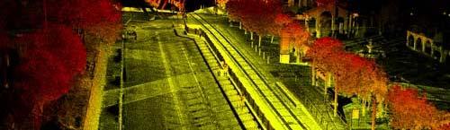
37 Ortho Contours Planimetrics Mobile Scanning 37
38 38
Photogrammetry: DTM Extraction & Editing
 Photogrammetry: DTM Extraction & Editing How can one determine the x, y, and z of a location? Approaches to DTM Extraction Ground surveying Digitized topographic maps Traditional photogrammetry Hardcopy
Chapters 1-4: Summary
 Chapters 1-4: Summary So far, we have been investigating the image acquisition process. Chapter 1: General introduction Chapter 2: Radiation source and properties Chapter 3: Radiation interaction with
Low-Cost Orthophoto Production Using OrthoMapper Software
 Low-Cost Orthophoto Production Using OrthoMapper Software Rick Day Penn State Cooperative Extension, Geospatial Technology Program, RGIS-Chesapeake Air Photos Historical air photos are available from a
Geometry of Aerial photogrammetry. Panu Srestasathiern, PhD. Researcher Geo-Informatics and Space Technology Development Agency (Public Organization)
") Geometry of Aerial photogrammetry Panu Srestasathiern, PhD. Researcher Geo-Informatics and Space Technology Development Agency (Public Organization) Image formation - Recap The geometry of imaging system
Geometry of Aerial photogrammetry Panu Srestasathiern, PhD. Researcher Geo-Informatics and Space Technology Development Agency (Public Organization) Image formation - Recap The geometry of imaging system
Technical Considerations and Best Practices in Imagery and LiDAR Project Procurement
 Technical Considerations and Best Practices in Imagery and LiDAR Project Procurement Presented to the 2014 WV GIS Conference By Brad Arshat, CP, EIT Date: June 4, 2014 Project Accuracy A critical decision
LIDAR MAPPING FACT SHEET
 1. LIDAR THEORY What is lidar? Lidar is an acronym for light detection and ranging. In the mapping industry, this term is used to describe an airborne laser profiling system that produces location and
Stereoscopic Models and Plotting
 Stereoscopic Models and Plotting Stereoscopic Viewing Stereoscopic viewing is the way the depth perception of the objects through BINOCULAR vision with much greater accuracy. رؤيه البعد الثالث و االحساس
UAV Flight Operations for Mapping. Precision. Accuracy. Reliability
 UAV Flight Operations for Mapping Precision. Accuracy. Reliability Part One: Why is Mapping different? Part Two: What about accuracy and precision? Part Three: What is the Workflow? Part Four: AGENDA What
Photogrammetry: DTM Extraction & Editing
 Photogrammetry: DTM Extraction & Editing Review of terms Vertical aerial photograph Perspective center Exposure station Fiducial marks Principle point Air base (Exposure Station) Digital Photogrammetry:
Map Compilation CHAPTER HISTORY
 CHAPTER 7 Map Compilation 7.1 HISTORY Producing accurate commercial maps from aerial photography began in the 1930s. The technology of stereomapping over the last 70 years has brought vast technological
Exterior Orientation Parameters
 Exterior Orientation Parameters PERS 12/2001 pp 1321-1332 Karsten Jacobsen, Institute for Photogrammetry and GeoInformation, University of Hannover, Germany The georeference of any photogrammetric product
Lecture 5. Relief displacement. Parallax. Monoscopic and stereoscopic height measurement. Photo Project. Soft-copy Photogrammetry.
 NRMT 2270, Photogrammetry/Remote Sensing Lecture 5 Relief displacement. Parallax. Monoscopic and stereoscopic height measurement. Photo Project. Soft-copy Photogrammetry. Tomislav Sapic GIS Technologist
POSITIONING A PIXEL IN A COORDINATE SYSTEM
 GEOREFERENCING AND GEOCODING EARTH OBSERVATION IMAGES GABRIEL PARODI STUDY MATERIAL: PRINCIPLES OF REMOTE SENSING AN INTRODUCTORY TEXTBOOK CHAPTER 6 POSITIONING A PIXEL IN A COORDINATE SYSTEM The essential
UAV Surveying II. Precision. Accuracy. Reliability
 UAV Surveying II Precision. Accuracy. Reliability Part One: Project Lifecycle Deliverables Part Two: Evaluation of UAV Data Accuracy and Examples of Error Part Three: AGENDA Review of Results Examples
Chapters 1 5. Photogrammetry: Definition, introduction, and applications. Electro-magnetic radiation Optics Film development and digital cameras
 Chapters 1 5 Chapter 1: Photogrammetry: Definition, introduction, and applications Chapters 2 4: Electro-magnetic radiation Optics Film development and digital cameras Chapter 5: Vertical imagery: Definitions,
Chapters 1 7: Overview
 Chapters 1 7: Overview Photogrammetric mapping: introduction, applications, and tools GNSS/INS-assisted photogrammetric and LiDAR mapping LiDAR mapping: principles, applications, mathematical model, and
Chapters 1 7: Overview
 Chapters 1 7: Overview Chapter 1: Introduction Chapters 2 4: Data acquisition Chapters 5 7: Data manipulation Chapter 5: Vertical imagery Chapter 6: Image coordinate measurements and refinements Chapter
TERRESTRIAL AND NUMERICAL PHOTOGRAMMETRY 1. MID -TERM EXAM Question 4
 TERRESTRIAL AND NUMERICAL PHOTOGRAMMETRY 1. MID -TERM EXAM Question 4 23 November 2001 Two-camera stations are located at the ends of a base, which are 191.46m long, measured horizontally. Photographs
Iowa Department of Transportation Office of Design. Photogrammetric Mapping Specifications
 Iowa Department of Transportation Office of Design Photogrammetric Mapping Specifications March 2015 1 Purpose of Manual These Specifications for Photogrammetric Mapping define the standards and general
Creating an Event Theme from X, Y Data
 Creating an Event Theme from X, Y Data In Universal Transverse Mercator (UTM) Coordinates Eastings (measured in meters) typically have 6 digits left of the decimal. Northings (also in meters) typically
Chapters 1 5. Photogrammetry: Definition, introduction, and applications. Electro-magnetic radiation Optics Film development and digital cameras
 Chapters 1 5 Chapter 1: Photogrammetry: Definition, introduction, and applications Chapters 2 4: Electro-magnetic radiation Optics Film development and digital cameras Chapter 5: Vertical imagery: Definitions,
Overview. Image Geometric Correction. LA502 Special Studies Remote Sensing. Why Geometric Correction?
 LA502 Special Studies Remote Sensing Image Geometric Correction Department of Landscape Architecture Faculty of Environmental Design King AbdulAziz University Room 103 Overview Image rectification Geometric
CHAPTER 10. Digital Mapping and Earthwork
 CHAPTER 10 Digital Mapping and Earthwork www.terrainmap.com/rm22.html CE 316 March 2012 348 10.1 Introduction 349 10.2 Single Images 10.2.1 Rectified Photograph With a single photograph, X,Y data can be
Measurement of Direction: Bearing vs. Azimuth
 Week 5 Monday Measurement of Direction: Bearing vs. Azimuth Bearing Is an angle of 90 o or less Measured from either North or South in easterly & westerly directions. North 22 o West, South 89 o West,
Training i Course Remote Sensing Basic Theory & Image Processing Methods September 2011
 Training i Course Remote Sensing Basic Theory & Image Processing Methods 19 23 September 2011 Geometric Operations Michiel Damen (September 2011) damen@itc.nl ITC FACULTY OF GEO-INFORMATION SCIENCE AND
Orthophotography and LiDAR Terrain Data Collection Rogue River, Oregon Final Report
 Orthophotography and LiDAR Terrain Data Collection Rogue River, Oregon Final Report Prepared by Sky Research, Inc. 445 Dead Indian Memorial Road Ashland, OR 97520 Prepared for Rogue Valley Council of Governments
Course Outline (1) #6 Data Acquisition for Built Environment. Fumio YAMAZAKI
 #6 Data Acquisition for Built Environment. Fumio YAMAZAKI") AT09.98 Applied GIS and Remote Sensing for Disaster Mitigation #6 Data Acquisition for Built Environment 9 October, 2002 Fumio YAMAZAKI yamazaki@ait.ac.th http://www.star.ait.ac.th/~yamazaki/ Course Outline
AT09.98 Applied GIS and Remote Sensing for Disaster Mitigation #6 Data Acquisition for Built Environment 9 October, 2002 Fumio YAMAZAKI yamazaki@ait.ac.th http://www.star.ait.ac.th/~yamazaki/ Course Outline
TRAINING MATERIAL HOW TO OPTIMIZE ACCURACY WITH CORRELATOR3D
 TRAINING MATERIAL WITH CORRELATOR3D Page2 Contents 1. UNDERSTANDING INPUT DATA REQUIREMENTS... 4 1.1 What is Aerial Triangulation?... 4 1.2 Recommended Flight Configuration... 4 1.3 Data Requirements for
PLS - EXAMINATION PREPARATION PHOTOGRAMMETRY 101. A paper on the principles of photogrammetric mapping
 Photogrammetric Consultants PLS - EXAMINATION PREPARATION PHOTOGRAMMETRY 101 A paper on the principles of photogrammetric mapping Photogrammetry is the art and science of obtaining reliable measurements
SimActive and PhaseOne Workflow case study. By François Riendeau and Dr. Yuri Raizman Revision 1.0
 SimActive and PhaseOne Workflow case study By François Riendeau and Dr. Yuri Raizman Revision 1.0 Contents 1. Introduction... 2 1.1. Simactive... 2 1.2. PhaseOne Industrial... 2 2. Testing Procedure...
QUESTIONS & ANSWERS FOR. ORTHOPHOTO & LiDAR AOT
 QUESTIONS & ANSWERS FOR ORTHOPHOTO & LiDAR AOT Question# 1. Section 3.2 Will the imagery be clipped to the 1000m boundary? If so, what color will be used for null valued pixels? Yes, the imagery will be
Section G. POSITIONAL ACCURACY DEFINITIONS AND PROCEDURES Approved 3/12/02
 Section G POSITIONAL ACCURACY DEFINITIONS AND PROCEDURES Approved 3/12/02 1. INTRODUCTION Modern surveying standards use the concept of positional accuracy instead of error of closure. Although the concepts
Journal Online Jaringan COT POLIPD (JOJAPS) Accuracy Assessment of Height Coordinate Using Unmanned Aerial Vehicle Images Based On Leveling Height
 Accuracy Assessment of Height Coordinate Using Unmanned Aerial Vehicle Images Based On Leveling Height") JOJAPS eissn 2504-8457 Abstract Journal Online Jaringan COT POLIPD (JOJAPS) Accuracy Assessment of Height Coordinate Using Unmanned Aerial Vehicle Images Based On Leveling Height Syamsul Anuar Bin Abu
JOJAPS eissn 2504-8457 Abstract Journal Online Jaringan COT POLIPD (JOJAPS) Accuracy Assessment of Height Coordinate Using Unmanned Aerial Vehicle Images Based On Leveling Height Syamsul Anuar Bin Abu
Mayden VP of Business Development Surdex Corporation
 Making Sense of Sensors Randy Mayden, Mayden VP of Business Development Surdex Corporation randym@surdex.com EARLYAERIAL PHOTOGRAPHY 2 FIRSTAERIAL CAMERA 3 AERIAL CAMERA SYSTEM DEVELOPMENT Aerial Camera
LiDAR & Orthophoto Data Report
 LiDAR & Orthophoto Data Report Tofino Flood Plain Mapping Data collected and prepared for: District of Tofino, BC 121 3 rd Street Tofino, BC V0R 2Z0 Eagle Mapping Ltd. #201 2071 Kingsway Ave Port Coquitlam,
PERFORMANCE OF LARGE-FORMAT DIGITAL CAMERAS
 PERFORMANCE OF LARGE-FORMAT DIGITAL CAMERAS K. Jacobsen Institute of Photogrammetry and GeoInformation, Leibniz University Hannover, Germany jacobsen@ipi.uni-hannover.de Inter-commission WG III/I KEY WORDS:
Absolute Horizontal Accuracies of Pictometry s Individual Orthogonal Frame Imagery
 A Pictometry International, Corp White Paper Absolute Horizontal Accuracies of Pictometry s Individual Orthogonal Frame Imagery Michael J. Zoltek VP, Surveying & Mapping Pictometry International, Corp
Chapters 1 9: Overview
 Chapters 1 9: Overview Chapter 1: Introduction Chapters 2 4: Data acquisition Chapters 5 9: Data manipulation Chapter 5: Vertical imagery Chapter 6: Image coordinate measurements and refinements Chapters
LPS Project Manager User s Guide. November 2009
 LPS Project Manager User s Guide November 2009 Copyright 2009 ERDAS, Inc. All rights reserved. Printed in the United States of America. The information contained in this document is the exclusive property
III. TESTING AND IMPLEMENTATION
 MAPPING ACCURACY USING SIDE-LOOKING RADAR I MAGES ON TIlE ANALYTI CAL STEREOPLOTTER Sherman S.C. Wu, Francis J. Schafer and Annie Howington-Kraus U.S Geological Survey, 2255 N. Gemini Drive, Flagstaff,
EVOLUTION OF POINT CLOUD
 Figure 1: Left and right images of a stereo pair and the disparity map (right) showing the differences of each pixel in the right and left image. (source: https://stackoverflow.com/questions/17607312/difference-between-disparity-map-and-disparity-image-in-stereo-matching)
2. POINT CLOUD DATA PROCESSING
 Point Cloud Generation from suas-mounted iphone Imagery: Performance Analysis A. D. Ladai, J. Miller Towill, Inc., 2300 Clayton Road, Suite 1200, Concord, CA 94520-2176, USA - (andras.ladai, jeffrey.miller)@towill.com
Sasanka Madawalagama Geoinformatics Center Asian Institute of Technology Thailand
 Sasanka Madawalagama Geoinformatics Center Asian Institute of Technology Thailand This learning material was not prepared by ADB. The views expressed in this document are the views of the author/s and
GUIDELINES FOR THE IN SITU GEOMETRIC CALIBRATION OF THE AERIAL CAMERA SYSTEM
 GUIDELINES FOR THE IN SITU GEOMETRIC CALIBRATION OF THE AERIAL CAMERA SYSTEM These guidelines have been developed by the Primary Data Acquisition Division and the Camera Calibration Committee, and have
Using ArcGIS Server Data to Assist in Planimetric Update Process. Jim Stout - IMAGIS Rick Hammond Woolpert
 Using ArcGIS Server Data to Assist in Planimetric Update Process Jim Stout - IMAGIS Rick Hammond Woolpert Using ArcGIS Server Data to Assist in Planimetric Update Process Jim Stout - IMAGIS Rick Hammond
Extracting Elevation from Air Photos
 Extracting Elevation from Air Photos TUTORIAL A digital elevation model (DEM) is a digital raster surface representing the elevations of a terrain for all spatial ground positions in the image. Traditionally
ON THE USE OF MULTISPECTRAL AND STEREO DATA FROM AIRBORNE SCANNING SYSTEMS FOR DTM GENERATION AND LANDUSE CLASSIFICATION
 ON THE USE OF MULTISPECTRAL AND STEREO DATA FROM AIRBORNE SCANNING SYSTEMS FOR DTM GENERATION AND LANDUSE CLASSIFICATION Norbert Haala, Dirk Stallmann and Christian Stätter Institute for Photogrammetry
COMPARATIVE CHARACTERISTICS OF DEM OBTAINED FROM SATELLITE IMAGES SPOT-5 AND TK-350
 COMPARATIVE CHARACTERISTICS OF DEM OBTAINED FROM SATELLITE IMAGES SPOT-5 AND TK-350 Dr. V. F. Chekalin a*, M. M. Fomtchenko a* a Sovinformsputnik, 47, Leningradsky Pr., 125167 Moscow, Russia common@sovinformsputnik.com
Basic Principles of Photogrammetry
 Basic Principles of Photogrammetry Annual Conference of PSLS January 13 16, 2019 Hershey, PA Frank Derby, PhD Penn State University Lehman, PA 18627 Workshop Content General Principles of Photogrammetry
ENY-C2005 Geoinformation in Environmental Modeling Lecture 4b: Laser scanning
 1 ENY-C2005 Geoinformation in Environmental Modeling Lecture 4b: Laser scanning Petri Rönnholm Aalto University 2 Learning objectives To recognize applications of laser scanning To understand principles
Calibration of IRS-1C PAN-camera
 Calibration of IRS-1C PAN-camera Karsten Jacobsen Institute for Photogrammetry and Engineering Surveys University of Hannover Germany Tel 0049 511 762 2485 Fax -2483 Email karsten@ipi.uni-hannover.de 1.
Light Detection and Ranging (LiDAR)
") Light Detection and Ranging (LiDAR) http://code.google.com/creative/radiohead/ Types of aerial sensors passive active 1 Active sensors for mapping terrain Radar transmits microwaves in pulses determines
Light Detection and Ranging (LiDAR) http://code.google.com/creative/radiohead/ Types of aerial sensors passive active 1 Active sensors for mapping terrain Radar transmits microwaves in pulses determines
AUTOMATIC IMAGE ORIENTATION BY USING GIS DATA
 AUTOMATIC IMAGE ORIENTATION BY USING GIS DATA Jeffrey J. SHAN Geomatics Engineering, School of Civil Engineering Purdue University IN 47907-1284, West Lafayette, U.S.A. jshan@ecn.purdue.edu Working Group
Quality Accuracy Professionalism
 GeoWing - who are we? Mapping Data Service Provider Lidar Multispectral Topographic and Planimetric Maps Elevation Models Point Clouds / 3D Models Orthophotography FAA-Authorized UAS Operators WOSB / DBE
THE INTERIOR AND EXTERIOR CALIBRATION FOR ULTRACAM D
 THE INTERIOR AND EXTERIOR CALIBRATION FOR ULTRACAM D K. S. Qtaishat, M. J. Smith, D. W. G. Park Civil and Environment Engineering Department, Mu ta, University, Mu ta, Karak, Jordan, 61710 khaldoun_q@hotamil.com
Chapter 1: Overview. Photogrammetry: Introduction & Applications Photogrammetric tools:
 Chapter 1: Overview Photogrammetry: Introduction & Applications Photogrammetric tools: Rotation matrices Photogrammetric point positioning Photogrammetric bundle adjustment This chapter will cover the
Lecture 4. Image Georeferencing, Accuracy and Precision, File Geodatabase
 Lecture 4 Image Georeferencing, Accuracy and Precision, File Geodatabase Tomislav Sapic GIS Technologist Faculty of Natural Resources Management Lakehead University Why Georeference? Images of the surface
KEY WORDS: IKONOS, Orthophotos, Relief Displacement, Affine Transformation
 GRATIO OF DIGITAL ORTHOPHOTOS FROM IKOOS GO IMAGS Liang-Chien Chen and Chiu-Yueh Lo Center for Space and Remote Sensing Research. ational Central University Tel: 886-3-47151 xt.76 Fax: 886-3-455535 lcchen@csrsr.ncu.edu.tw
CONSISTENT COLOR RESAMPLE IN DIGITAL ORTHOPHOTO PRODUCTION INTRODUCTION
 CONSISTENT COLOR RESAMPLE IN DIGITAL ORTHOPHOTO PRODUCTION Yaron Katzil 1, Yerach Doytsher 2 Mapping and Geo-Information Engineering Faculty of Civil and Environmental Engineering Technion - Israel Institute
GIS Data Collection. This chapter reviews the main methods of GIS data capture and transfer and introduces key practical management issues.
 9 GIS Data Collection OVERVIEW This chapter reviews the main methods of GIS data capture and transfer and introduces key practical management issues. It distinguishes between primary (direct measurement)
Photogrammetric Procedures for Digital Terrain Model Determination
 Photogrammetric Procedures for Digital Terrain Model Determination Hartmut ZIEMANN and Daniel GROHMANN 1 Introduction Photogrammetric procedures for digital terrain model (DTM) data determination fall
ADS40 Calibration & Verification Process. Udo Tempelmann*, Ludger Hinsken**, Utz Recke*
 ADS40 Calibration & Verification Process Udo Tempelmann*, Ludger Hinsken**, Utz Recke* *Leica Geosystems GIS & Mapping GmbH, Switzerland **Ludger Hinsken, Author of ORIMA, Konstanz, Germany Keywords: ADS40,
TO Ka Yi, Lizzy 6 May
 TO Ka Yi, Lizzy 6 May 2017 1 Contents Basic concepts Practical Issues Examples 2 Data Acquisition Source of Energy Data Products Interpretation & Analysis Digital Propagation through the atmosphere Data
ArcMap as a quality assurance tool in Photogrammetry Ron Frederiks. Abstract
 ArcMap as a quality assurance tool in Photogrammetry Ron Frederiks Abstract This paper presents the use of ArcMap, 3-D Analyst, Spatial Analyst and Ianko s ETGeoWizards to perform quality assurance of
Elements of Analytical Photogrammetry
 Chapter 5 Elements of Analytical hotogrammetry 5.1 Introduction, Concept of Image and Object Space hotogrammetry is the science of obtaining reliable information about objects and of measuring and interpreting
DEVELOPMENT OF ORIENTATION AND DEM/ORTHOIMAGE GENERATION PROGRAM FOR ALOS PRISM
 DEVELOPMENT OF ORIENTATION AND DEM/ORTHOIMAGE GENERATION PROGRAM FOR ALOS PRISM Izumi KAMIYA Geographical Survey Institute 1, Kitasato, Tsukuba 305-0811 Japan Tel: (81)-29-864-5944 Fax: (81)-29-864-2655
ORTHOPHOTO PRODUCTION FROM AERIAL PHOTOGRAPH BY USING MATLAB AND GIS
 International Journal of Civil Engineering and Technology (IJCIET) Volume 9, Issue 9, September 2018, pp. 156 164, Article ID: IJCIET_09_09_018 Available online at http://www.iaeme.com/ijciet/issues.asp?jtype=ijciet&vtype=9&itype=9
9/14/2011. Contents. Lecture 3: Spatial Data Acquisition in GIS. Dr. Bo Wu Learning Outcomes. Data Input Stream in GIS
 Contents Lecture 3: Spatial Data Acquisition in GIS Dr. Bo Wu lsbowu@polyu.edu.hk 1. Learning outcomes. Data acquisition: Manual digitization 3. Data acquisition: Field survey 4. Data acquisition: Remote
Georeferencing in ArcGIS
 Georeferencing in ArcGIS Georeferencing In order to position images on the surface of the earth, they need to be georeferenced. Images are georeferenced by linking unreferenced features in the image with
OPTIMIZED PATCH BACKPROJECTION IN ORTHORECTIFICATION FOR HIGH RESOLUTION SATELLITE IMAGES
 OPTIMIZED PATCH BACKPROJECTION IN ORTHORECTIFICATION FOR HIGH RESOLUTION SATELLITE IMAGES Liang-Chien Chen *, Tee-Ann Teo, Jiann-Yeou Rau Center for Space and Remote Sensing Research, National Central
ALS40 Airborne Laser Scanner
 ALS40 Airborne Laser Scanner Airborne LIDAR for Professionals High Performance Laser Scanning Direct Measurement of Ground Surface from the Air The ALS40 Airborne Laser Scanner measures the topography
High resolution survey and orthophoto project of the Dosso-Gaya region in the Republic of Niger. by Tim Leary, Woolpert Inc.
 High resolution survey and orthophoto project of the Dosso-Gaya region in the Republic of Niger by Tim Leary, Woolpert Inc. Geospatial Solutions Photogrammetry & Remote Sensing LiDAR Professional Surveying
GEOMETRIC AND MAPPING POTENTIAL OF WORLDVIEW-1 IMAGES
 GEOMETRIC AND MAPPING POTENTIAL OF WORLDVIEW-1 IMAGES G. Buyuksalih*, I. Baz*, S. Bayburt*, K. Jacobsen**, M. Alkan *** * BIMTAS, Tophanelioglu Cad. ISKI Hizmet Binasi No:62 K.3-4 34460 Altunizade-Istanbul,
GMAT9300 Aerial and Satellite Imaging Systems
 GMAT9300 Aerial and Satellite Imaging Systems Semester 2, COURSE DETAILS Units of Credit 6 Contact hours 5 Class Tuesday 12.00 to 15.00 BUS232 Workshop Wednesday 12.00 to 14.00 MAT308 and CivEng Lab 201
STARTING WITH DRONES. Data Collection and Remote Sensing with UAVs, etc. Dr. Bill Hazelton LS
 STARTING WITH DRONES Data Collection and Remote Sensing with UAVs, etc. Dr. Bill Hazelton LS What this Talk is About UAV-based data acquisition: What you need to get involved Processes in getting spatial
Using Mobile LiDAR To Efficiently Collect Roadway Asset and Condition Data. Pierre-Paul Grondin, B.Sc. Surveying
 Using Mobile LiDAR To Efficiently Collect Roadway Asset and Condition Data Pierre-Paul Grondin, B.Sc. Surveying LIDAR (Light Detection and Ranging) The prevalent method to determine distance to an object
ACCURACY ANALYSIS FOR NEW CLOSE-RANGE PHOTOGRAMMETRIC SYSTEMS
 ACCURACY ANALYSIS FOR NEW CLOSE-RANGE PHOTOGRAMMETRIC SYSTEMS Dr. Mahmoud El-Nokrashy O. ALI Prof. of Photogrammetry, Civil Eng. Al Azhar University, Cairo, Egypt m_ali@starnet.com.eg Dr. Mohamed Ashraf
Hamilton County Enhances GIS Base Mapping with 1-foot Contours
 Hamilton County Enhances GIS Base Mapping with 1-foot Contours Presented by Larry Stout, Hamilton County GIS Manager Brad Fugate, Woolpert Inc. Today s Presentation Hamilton County s 2004 Base Mapping
BUNDLE BLOCK ADJUSTMENT WITH HIGH RESOLUTION ULTRACAMD IMAGES
 BUNDLE BLOCK ADJUSTMENT WITH HIGH RESOLUTION ULTRACAMD IMAGES I. Baz*, G. Buyuksalih*, K. Jacobsen** * BIMTAS, Tophanelioglu Cad. ISKI Hizmet Binasi No:62 K.3-4 34460 Altunizade-Istanbul, Turkey gb@bimtas.com.tr
Todd King, PLS, LEED AP Business Developer
 Todd King, PLS, LEED AP Business Developer TKing@McKimCreed.com 38 YEARS 378 EMPLOYEES ENR Top 500 Design Firm ENR Top 200 Environmental ENR Southeast Engineer Firms POB Geospatial Top 100 Top 50 Trenchless
Leica Systems Overview
 RC30 AERIAL CAMERA SYSTEM Leica Systems Overview The Leica RC30 aerial film camera is the culmination of decades of development, started with Wild's first aerial camera in the 1920s. Beautifully engineered
Aalborg Universitet. Published in: Accuracy Publication date: Document Version Early version, also known as pre-print
 Aalborg Universitet A method for checking the planimetric accuracy of Digital Elevation Models derived by Airborne Laser Scanning Høhle, Joachim; Øster Pedersen, Christian Published in: Accuracy 2010 Publication
Reality Modeling Drone Capture Guide
 Reality Modeling Drone Capture Guide Discover the best practices for photo acquisition-leveraging drones to create 3D reality models with ContextCapture, Bentley s reality modeling software. Learn the
Centre for Digital Image Measurement and Analysis, School of Engineering, City University, Northampton Square, London, ECIV OHB
 HIGH ACCURACY 3-D MEASUREMENT USING MULTIPLE CAMERA VIEWS T.A. Clarke, T.J. Ellis, & S. Robson. High accuracy measurement of industrially produced objects is becoming increasingly important. The techniques
University of Technology Building & Construction Department / Remote Sensing & GIS lecture
 5. Corrections 5.1 Introduction 5.2 Radiometric Correction 5.3 Geometric corrections 5.3.1 Systematic distortions 5.3.2 Nonsystematic distortions 5.4 Image Rectification 5.5 Ground Control Points (GCPs)
Accuracy Assessment of POS AVX 210 integrated with the Phase One ixu150
 White Paper 3/17/2016 Accuracy Assessment of POS AVX 210 integrated with the Phase One ixu150 Omer Mian, Joe Hutton, Greg Lipa, James Lutes, Damir Gumerov, Srdjan Sobol Applanix, William Chan - GeoPixel
ACCURACY OF DIGITAL ORTHOPHOTOS FROM HIGH RESOLUTION SPACE IMAGERY
 ACCURACY OF DIGITAL ORTHOPHOTOS FROM HIGH RESOLUTION SPACE IMAGERY Jacobsen, K.*, Passini, R. ** * University of Hannover, Germany ** BAE Systems ADR, Pennsauken, NJ, USA acobsen@ipi.uni-hannover.de rpassini@adrinc.com
Introduction to Computer Vision. Introduction CMPSCI 591A/691A CMPSCI 570/670. Image Formation
 Introduction CMPSCI 591A/691A CMPSCI 570/670 Image Formation Lecture Outline Light and Optics Pinhole camera model Perspective projection Thin lens model Fundamental equation Distortion: spherical & chromatic
3D DIGITAL MODELING OF MODERN TIMES BUILDING FOR PRESERVATION AND RESTORATION
 3D DIGITAL MODELING OF MODERN TIMES BUILDING FOR PRESERVATION AND RESTORATION W.J. Oh a *, S.H. Han b, H.C. Yoon c, Y.S. Bae d, S.H. Song e a Dept. of Land Information Management, ChungCheong University,
U.S. Geological Survey (USGS) - National Geospatial Program (NGP) and the American Society for Photogrammetry and Remote Sensing (ASPRS)
 - National Geospatial Program (NGP) and the American Society for Photogrammetry and Remote Sensing (ASPRS)") U.S. Geological Survey (USGS) - National Geospatial Program (NGP) and the American Society for Photogrammetry and Remote Sensing (ASPRS) Summary of Research and Development Efforts Necessary for Assuring
U.S. Geological Survey (USGS) - National Geospatial Program (NGP) and the American Society for Photogrammetry and Remote Sensing (ASPRS) Summary of Research and Development Efforts Necessary for Assuring
The Accuracy of Determining the Volumes Using Close Range Photogrammetry
 IOSR Journal of Mechanical and Civil Engineering (IOSR-JMCE) e-issn: 2278-1684,p-ISSN: 2320-334X, Volume 12, Issue 2 Ver. VII (Mar - Apr. 2015), PP 10-15 www.iosrjournals.org The Accuracy of Determining
GALILEO SISCAM APPROACH TO DIGITAL PHOTOGRAMMETRY. F. Flamigni A. Viti Galileo Siscam S.p.A.
 GALILEO SISCAM APPROACH TO DIGITAL PHOTOGRAMMETRY F. Flamigni A. Viti Galileo Siscam S.p.A. ABSTRACT: The application of the least squares matching procedure to an analytical stereoplotter is described.
ifp Universität Stuttgart Performance of IGI AEROcontrol-IId GPS/Inertial System Final Report
 Universität Stuttgart Performance of IGI AEROcontrol-IId GPS/Inertial System Final Report Institute for Photogrammetry (ifp) University of Stuttgart ifp Geschwister-Scholl-Str. 24 D M. Cramer: Final report
THE EUROSDR PROJECT AUTOMATED CHECKING AND IMPROVING OF DIGITAL TERRAIN MODELS
 THE EUROSDR PROJECT AUTOMATED CHECKING AND IMPROVING OF DIGITAL TERRAIN MODELS Dr. Joachim Höhle Aalborg University 9220 Aalborg, Denmark jh@land.aau.dk ABSTRACT The results of the research project Checking
Understanding Variability
 Understanding Variability Why so different? Light and Optics Pinhole camera model Perspective projection Thin lens model Fundamental equation Distortion: spherical & chromatic aberration, radial distortion
Geometric Rectification of Remote Sensing Images
 Geometric Rectification of Remote Sensing Images Airborne TerrestriaL Applications Sensor (ATLAS) Nine flight paths were recorded over the city of Providence. 1 True color ATLAS image (bands 4, 2, 1 in
APPLICATION AND ACCURACY EVALUATION OF LEICA ADS40 FOR LARGE SCALE MAPPING
 APPLICATION AND ACCURACY EVALUATION OF LEICA ADS40 FOR LARGE SCALE MAPPING WenYuan Hu a, GengYin Yang b, Hui Yuan c,* a, b ShanXi Provincial Survey and Mapping Bureau, China - sxgcchy@public.ty.sx.cn c
The Applanix Approach to GPS/INS Integration
 Lithopoulos 53 The Applanix Approach to GPS/INS Integration ERIK LITHOPOULOS, Markham ABSTRACT The Position and Orientation System for Direct Georeferencing (POS/DG) is an off-the-shelf integrated GPS/inertial
Leica Photogrammetry Suite Automatic Terrain Extraction
 Leica Photogrammetry Suite Automatic Terrain Extraction Copyright 2006 Leica Geosystems Geospatial Imaging, LLC All rights reserved. Printed in the United States of America. The information contained in
MONO-IMAGE INTERSECTION FOR ORTHOIMAGE REVISION
 MONO-IMAGE INTERSECTION FOR ORTHOIMAGE REVISION Mohamed Ibrahim Zahran Associate Professor of Surveying and Photogrammetry Faculty of Engineering at Shoubra, Benha University ABSTRACT This research addresses