Basic Principles of Photogrammetry
|
|
|
- Kerry Singleton
- 5 years ago
- Views:
Transcription
1 Basic Principles of Photogrammetry Annual Conference of PSLS January 13 16, 2019 Hershey, PA Frank Derby, PhD Penn State University Lehman, PA 18627

2 Workshop Content General Principles of Photogrammetry Applications of aerial photogrammetry UAV Flight planning Applications of UAV Digital photography Photo control points Geo-referencing Geo-rectification Deliverables
3 Expected Outcomes Upon completion, participants will understand: Applications of aerial photogrammetry Analog Photography Digital photography UAV Flight planning considerations Georeferencing Georectification Procedures for creating orthophotographs
4 What is Photogrammetry A procedure for acquiring data to map a region of the earth s surface or some phenomenon without making direct contact with the feature or phenomenon. Also called remote sensing, data acquisition is accomplished with sensors mounted on platforms such as aircraft, drones, helicopter, satellites, balloons, etc. Sensors may be photo cameras, infrared sensors, charge coupled devices Sensors operate using the visible region of the electromagnetic spectrum.
5 Photogrammetric Sensors Two main types of sensors Passive Sensors detect energy from the physical environment. Passive sensors gather target energy through the detection of light, radiation, heat or other phenomena occurring in the subject's environment. Active Sensors have their own source of energy. They actively direct wave signals onto targets and measure the backscatter reflected back to it.
6 Photogrammetric Sensors Active Sensors Radar EDM LiDar Lasers Passive Sensors Camera Human eye UV Imagers Thermal IR sensors Masers

7 The Electromagnetic Spectrum
8 Photogrammetric Principles Ground coverage Area of the ground that is captured in a single frame.
9 Photogrammetric Principles End lap the overlap area between adjacent photos on a flight line Air Base the distance between consecutive exposure stations.
10 Photogrammetric Principles Side lap The overlap are between photos on adjacent flight lines.
11 Large Area photogrammetric Project Manned aircraft platform Analog Film format = 9 inch x 9 inch Flying Height = 1000 ft ft. Fixed Focal length camera


12 Applications of Traditional Photogrammetry Topographic mapping Digital elevation mapping Ortho-photo maps Computing volumes of Earthwork Historical preservation Tax maps Cadastral base maps Zoning and planning Etc.
13 Flat Terrain SSSSSSSSSS = PPPPPPPPP dddddddddddddddd = aaaa GGGGGGGGGGGG dddddddddddddddd AAAA Photo scale = FFFFFFFFFF LLLLLLLLLLL FFFFFFFFFFFF HHHHHHHHHHH =ff HH H = Height above ground f = Focal Length ab = Photo distance AB = Ground distance
14 Variable Terrain Use Average Photo scale (S av ) Photo Scale S av = ff HH h aaaa H = Height above Datum H = Height above ground h av = Average height of the terrain

15 Ground Coverage Assuming a camera whose focal length is 152.4mm Flying height = 1000m Frame format of m square, The ground coverage is given by aaaa AAAA = ff HH ; AAAA = aaaa HH ff AAAA = mm xx 1000mm mm = m For a square format the ground coverage = = 3395sq. m
16 Displacement (ab) Relief Displacement aaaa = rrr HH Height of pole (h) h = aaaa HH rr
17 Photo Scale Scale selection depends on the purpose of the project. Finished scale of the deliverables The smallest detail that needs to be shown Dictated by the resolving power of the sensor.
18 Resolving Power of Analog Cameras The resolving power of an objective lens is measured by its ability to differentiate two lines or points in an object. The greater the resolving power, the smaller the minimum distance between two lines or points that can still be distinguished. Given in number of lines per millimeter. E.g. 80 lines/mm
19 Resolving Power and Photo Scale Supposing that in a photogrammetric mapping project, the road marking on a highway need to be shown. Given that the width of the marking is 4 inches (100 mm), what should the minimum photo scale be, if the power of the camera is 80 lines/mm? Solution: The smallest object that the camera can capture is: 1 80 mmmm = mmmm Min. Photo scale = mmmm 100 mmmm =
20 Resolving Power and Photo Scale Assuming that the focal length of the camera is 6 inches (0.5 ft), what should be the maximum flying height? Solution: 1 = H Maximum Flying Height (H) = 4000 ft


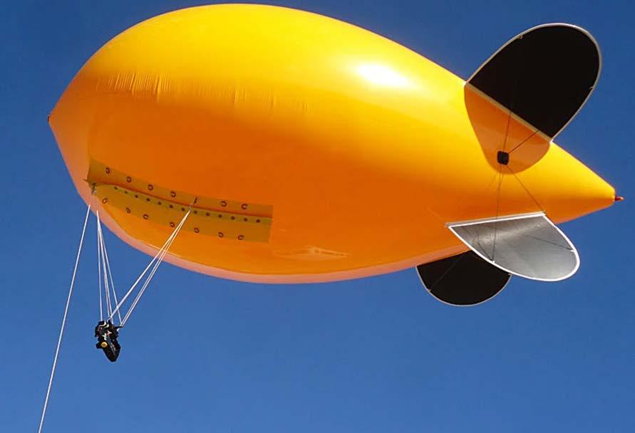


21 Small Area Photogrammetric Platforms Aircraft Helicopters Blimps Kites Drones Balloons Pigeons
22 Applications in Small Area Mapping Aerial photography Mapping Volumetric Surveys Contour Mapping Topographic Mapping Digital Terrain Modelling Temporal/Spatial Correlation for Terrain Reconstruction Geophysical Survey
23 Civilian Applications Security awareness; Disaster response, including search and support to rescuers; Communications and broadcast, including news/sporting event coverage; Cargo transport; Spectral and thermal analysis; Critical infrastructure monitoring and inspection, including power facilities, ports, bridges, and pipelines; Commercial photography, aerial mapping for small areas, and advertising.
24 Resolution of Digital Cameras Resolution refers to the number of pixels a camera can capture (in Megapixels). One Megapixel approximates a million pixels. Each pixel contains a digital number (DN) which corresponds to a digital color representation of the features within the corresponding ground.
25 36mm x 24mm (Full format) 23.6mm x 15.7mm (1.5x) 22.2mm x 14.8mm (1.6x) 17.3mm x 13mm (2x) 13.2mm x 8.8mm (2.7x) Sensor Frame Formats
26 Pixel Resolution Pixel size is determined in metric units For a full fame camera, frame size in 36mm x 24mm Surface Area is 36 x 24 = 864 sq. mm. For a 20 MP camera, a pixel size is = 6.42µm x 6.42µm xxxxxxxxxxxx = mm For a frame size of 13.2mm x 8.8mm, the pixel size is 2.4µm x 2.4µm.
27 Pixel Resolution If the UAV camera has a focal length of 28 mm and flies at 390 ft. above ground, then the ground resolution will be: 390 ft. = m ~ 119 m ff = aaaa HH AAAA then AAAA = aaaa xx HH ff AB = mmmm xx mmmm 28 mmmm = mmmm on the ground For a square pixel, the ground resolution is 2.7 cm x 2.7 cm

28 Ground Coverage Length ff = aaaa HH AAAA AB = AB = m HH aaaa ff = xx 24mmmm 28mmmm 24 mm 36 mm Width WW = mm xx 36mmmm 28mmmm = m Total Area = x = 15,606 sq. m
29 End Lap Assuming 75% End lap, End lap = 0.75 x m = m Air base = m Air Base = m Air base End lap
30 Intervalometer Setting Assuming the aircraft travels at 10 meters per second, the intervalometer setting will be: Air base IS = mm 10 mm = 2.55 sec. ~ 2 sec. The UAV will take a picture every 2 seconds. Note: The average UAV travels art 13m/sec. End lap
31 Image Size For a 20 MP camera, the size of a color photograph will be: Assuming 1. Three color bands (Red, Green, Blue) per pixel 2. Each pixel requires 1 byte of memory, 20 MB x 3 color bands = 60 MB for the raw image Therefore the type of storage medium becomes important.
32 Maximum Height of Features Assuming 75% End lap, End lap = 0.75 x m = m Air base = m Air Base = m Air base End lap
33 Maximum Height of Features Still using 75% End lap, End lap = 0.75 x m = m; Air base = m Air base (B) Tallest Feature (h) HH = h ; h = HH(GG BB) GG GG BB GG H h = HH = m G h Remember that tree tops are not pointed End lap
34 Maximum Feature Height Assuming 70% End lap, and Flying of Height of 80 m, Then we can find the maximum height of features. Still using f = 28 mm Ground coverage is ff HH = aaaa AAAA G = 24 mmmm xx 80 mm 28 mmmm = 68 m AAAA = aaaa HH End lap =0.7 x 68 m = 48 m ; Air Base (B)= = 20 m ff h = HH GG BB GG ; h = 80mm xx 48 mm 68 mm = m
35 Sources of Error Internal Lens distortion Film shrinkage Atmospheric refraction Relief Displacement External Rotations in x, y, z of the aircraft in relation the ground Shifts in X, Y, Z, in relation to a geographic coordinate system Errors in the ground control points
36 Relating Image points to Ground Coordinates Premarking or Paneling artificial points are placed at strategic locations on the ground in the project area prior to taking the aerial photography. Provides excellent control quality Useful in areas where there are scant details to be used as ground controls Use for controlling most precise photogrammetric work Extra work and expense incurred in acquiring and placing targets Targets could be moved between time of survey and photography Targets may not appear in favorable positions on the photograph
37 Relating Image points to Ground Coordinates Natural Targets Well defined identifiable points on the photograph are used as control points. The points are then surveyed and used as control points. Control points can be located at suitable locations in the project area. No extra cost for acquiring or placing targets
38 Photogrammetric Image Processing Georeferencing (Ground Registration) the process of aligning the pixels in the image to ground coordinate system. Accomplished through coordinate transformation process (Affine transformation in particular) Remote sensing specialists refer to georeferencing as georectification but the term has a different meaning in photogrammetry Georectification the process of removing effects of tilt, lens distortion and other errors form the the aerial photograph. The process is more complicated than georeferencing. Accomplished by applying mathematical principles of collinearity or coplanarity conditions and aerotriangulation processes
39 Affine Transformation A six parameter transformation which accounts for Unequal scale distortion, non-orthogonality of the axes, angular rotation, and translations in Eastings and Northings. The equations may be expressed using simpler notation of the form: EE = aa 0 + aa 1 xx + aa 2 yy NN = bb 0 + bb 1 xx + bb 2 yy When applied on a feature, the Affine transformation changes all characteristics including shape, scale orientation and size. Note that variations in elevations of points in the photograph are not accounted for.
40 Affine Transformation Given that x, y are in the photographic coordinate system, E, N are in the ground coordinate system, and ε is the lack of orthogonality in the axis. s x, s y are the scale factors for x and y axes respectively, and E 0, N 0 are the translations. ε, θ, s x, s y, E 0, N 0 are the six independent parameters which may be determined if at least three points (preferably more) have known coordinates in both systems.
41 Affine Transformation Determination of unknown parameters θθ = tan 1 aa 2 bb 2 ; εε θθ = tan 1 bb 1 aa 1 ; εε = εε θθ +θθ ss xx = aa 1 cos εε cos εε θθ ; ss yy = bb 2 cos εε cos θθ EE 0 = aa 0 ; NN 0 = bb 0
42 2-D Projective Transformation An eight parameter transformation XX = aa 1xx + bb 1 yy + cc 1 aa 3 xx+ bb 3 yy +1 YY = aa 2xx + bb 2 yy + cc 2 aa 3 xx+ bb 3 yy +1 x and y are tilted photo coordinates Since the transformation is non-linear, it is better to solve by least squares, after linearization.
43 2-D Projective Transformation Unknown parameters: a 1, b 1, c 1, a 2, b 2, c 2, a 3, b 3, are eight transformation parameters to solve for. These are functions of the eight unknowns: x 0, y 0, ω, φ, κ, X L, Y L, and H
44 Image Rotation and Translation
45 Collinearity Equations If there are a number of ground control points whose coordinates XYZ are known, then the process of analytical rectification can be performed based on the parameters derived from these coordinates. Satisfies the condition that the exposure station, any object point and its photo image all lie along a straight line in three dimensional space.

46 Creating Tie Points STA 4 WIL 1A STA 41 RD GYM WIL 1B
47 Collinearity Equations xx aa = xx 0 ff mm 11 XX AA XX LL + mm 12 YY AA YY LL + mm 13 ZZ AA ZZ LL mm 31 XX AA XX LL + mm 32 YY AA YY LL + mm 33 ZZ AA ZZ LL yy aa = yy 0 ff mm 11 XX AA XX LL + mm 12 YY AA YY LL + mm 13 ZZ AA ZZ LL mm 31 XX AA XX LL + mm 32 YY AA YY LL + mm 33 ZZ AA ZZ LL Where: mm 11 = cos φφ cos κκ mm 12 = sin ωω sin φφ cos κκ + cos ωω sin κκ mm 13 = cos ωω sin φφ cos κκ + sin ωω sin κκ mm 21 = cos φφ sin κκ mm 22 = sin ωω sin φφ sin κκ + cos ωω cos κκ mm 23 = cos ωω sin φφ sin κκ + sin ωω cos κκ mm 31 = sin φφ mm 32 = sin ωω cos φφ mm 33 = cos ωω cos φφ

48
49 Interior Orientation Exterior Orientation Digital Elevation Models Mosaics and color balancing Analytical Rectification

50 Digital Elevation Model (DEM) A digital elevation model is a bareearth raster grid referenced to a vertical datum. Elevation data from non-ground points such as bridges and roads, are excluded from digital elevation model. Elevation data from structures such as powerlines, buildings and towers, trees and other types of vegetation are also excluded from a DEM.
51 Digital Elevation Model A bare-earth elevation model is particularly useful in: Hydrologic modelling: Hydrologists use DEMs to delineate watersheds, calculate flow accumulation and flow direction. Terrain stability: Areas prone to avalanches are high slope areas with sparse vegetation. This is useful when planning a highway or residential subdivision. Soil mapping: DEMs assist in mapping soils which is a function of elevation (as well as geology, time and climate).
52

53 Mosaicked Ortho-photo
54 Digital Elevation Models Most users often feel that DEM derived using softcopy photogrammetric instruments will be free from error. User should be aware of several trade-offs: the process works well when the terrain is devoid of trees, buildings, overpasses, bridges, etc., which extend above the nominal terrain. The algorithm assumes these objects are terrain and computes the differential parallax and the resultant height of such surfaces which are then placed in the DEM.
55 Accuracy of DEMs The accuracy of the orthophoto is a function of the quality of the imagery, the ground control, the photogrammetric Aerotriangulation and the DEM. The DEM can have errors associated with it. The orthophoto may be derived from a DEM with building rooftops cleaned up, or even DEM with buildings and trees removed. The analyst should always have access to the metadata of how the DEM was generated.
56 Digital Surface Model A DSM captures the natural and built features on the Earth s surface. Digital Surface Model (DSM) Extruding features are tree canopy.


57 Digital Surface Model
58 DSM is particularly useful in: Digital Surface Model Runway approach zone encroachment. In aviation, DSMs can determine runway obstructions in the approach zone. Vegetation management. Along a transmission line, DSMs can see where and how much vegetation is encroaching. View obstruction. Urban planners use DSM to check how a proposed building would affect the views of residents and businesses. Inspecting Power lines and pipe lines for hazards
59 Thank You!
Photogrammetry: DTM Extraction & Editing
 Photogrammetry: DTM Extraction & Editing How can one determine the x, y, and z of a location? Approaches to DTM Extraction Ground surveying Digitized topographic maps Traditional photogrammetry Hardcopy
Introduction Photogrammetry Photos light Gramma drawing Metron measure Basic Definition The art and science of obtaining reliable measurements by mean
 Photogrammetry Review Neil King King and Associates Testing is an art Introduction Read the question Re-Read Read The question What is being asked Answer what is being asked Be in the know Exercise the
Photogrammetry: DTM Extraction & Editing
 Photogrammetry: DTM Extraction & Editing Review of terms Vertical aerial photograph Perspective center Exposure station Fiducial marks Principle point Air base (Exposure Station) Digital Photogrammetry:
Geometry of Aerial photogrammetry. Panu Srestasathiern, PhD. Researcher Geo-Informatics and Space Technology Development Agency (Public Organization)
") Geometry of Aerial photogrammetry Panu Srestasathiern, PhD. Researcher Geo-Informatics and Space Technology Development Agency (Public Organization) Image formation - Recap The geometry of imaging system
Geometry of Aerial photogrammetry Panu Srestasathiern, PhD. Researcher Geo-Informatics and Space Technology Development Agency (Public Organization) Image formation - Recap The geometry of imaging system
TERRESTRIAL AND NUMERICAL PHOTOGRAMMETRY 1. MID -TERM EXAM Question 4
 TERRESTRIAL AND NUMERICAL PHOTOGRAMMETRY 1. MID -TERM EXAM Question 4 23 November 2001 Two-camera stations are located at the ends of a base, which are 191.46m long, measured horizontally. Photographs
Low-Cost Orthophoto Production Using OrthoMapper Software
 Low-Cost Orthophoto Production Using OrthoMapper Software Rick Day Penn State Cooperative Extension, Geospatial Technology Program, RGIS-Chesapeake Air Photos Historical air photos are available from a
An Introduction to Lidar & Forestry May 2013
 An Introduction to Lidar & Forestry May 2013 Introduction to Lidar & Forestry Lidar technology Derivatives from point clouds Applied to forestry Publish & Share Futures Lidar Light Detection And Ranging
Chapters 1-4: Summary
 Chapters 1-4: Summary So far, we have been investigating the image acquisition process. Chapter 1: General introduction Chapter 2: Radiation source and properties Chapter 3: Radiation interaction with
Course Outline (1) #6 Data Acquisition for Built Environment. Fumio YAMAZAKI
 #6 Data Acquisition for Built Environment. Fumio YAMAZAKI") AT09.98 Applied GIS and Remote Sensing for Disaster Mitigation #6 Data Acquisition for Built Environment 9 October, 2002 Fumio YAMAZAKI yamazaki@ait.ac.th http://www.star.ait.ac.th/~yamazaki/ Course Outline
AT09.98 Applied GIS and Remote Sensing for Disaster Mitigation #6 Data Acquisition for Built Environment 9 October, 2002 Fumio YAMAZAKI yamazaki@ait.ac.th http://www.star.ait.ac.th/~yamazaki/ Course Outline
CHAPTER 10. Digital Mapping and Earthwork
 CHAPTER 10 Digital Mapping and Earthwork www.terrainmap.com/rm22.html CE 316 March 2012 348 10.1 Introduction 349 10.2 Single Images 10.2.1 Rectified Photograph With a single photograph, X,Y data can be
LIDAR MAPPING FACT SHEET
 1. LIDAR THEORY What is lidar? Lidar is an acronym for light detection and ranging. In the mapping industry, this term is used to describe an airborne laser profiling system that produces location and
LiDAR & Orthophoto Data Report
 LiDAR & Orthophoto Data Report Tofino Flood Plain Mapping Data collected and prepared for: District of Tofino, BC 121 3 rd Street Tofino, BC V0R 2Z0 Eagle Mapping Ltd. #201 2071 Kingsway Ave Port Coquitlam,
University of Technology Building & Construction Department / Remote Sensing & GIS lecture
 5. Corrections 5.1 Introduction 5.2 Radiometric Correction 5.3 Geometric corrections 5.3.1 Systematic distortions 5.3.2 Nonsystematic distortions 5.4 Image Rectification 5.5 Ground Control Points (GCPs)
Chapters 1 7: Overview
 Chapters 1 7: Overview Chapter 1: Introduction Chapters 2 4: Data acquisition Chapters 5 7: Data manipulation Chapter 5: Vertical imagery Chapter 6: Image coordinate measurements and refinements Chapter
Chapters 1 9: Overview
 Chapters 1 9: Overview Chapter 1: Introduction Chapters 2 4: Data acquisition Chapters 5 9: Data manipulation Chapter 5: Vertical imagery Chapter 6: Image coordinate measurements and refinements Chapters
TO Ka Yi, Lizzy 6 May
 TO Ka Yi, Lizzy 6 May 2017 1 Contents Basic concepts Practical Issues Examples 2 Data Acquisition Source of Energy Data Products Interpretation & Analysis Digital Propagation through the atmosphere Data
POSITIONING A PIXEL IN A COORDINATE SYSTEM
 GEOREFERENCING AND GEOCODING EARTH OBSERVATION IMAGES GABRIEL PARODI STUDY MATERIAL: PRINCIPLES OF REMOTE SENSING AN INTRODUCTORY TEXTBOOK CHAPTER 6 POSITIONING A PIXEL IN A COORDINATE SYSTEM The essential
Lecture 5. Relief displacement. Parallax. Monoscopic and stereoscopic height measurement. Photo Project. Soft-copy Photogrammetry.
 NRMT 2270, Photogrammetry/Remote Sensing Lecture 5 Relief displacement. Parallax. Monoscopic and stereoscopic height measurement. Photo Project. Soft-copy Photogrammetry. Tomislav Sapic GIS Technologist
SimActive and PhaseOne Workflow case study. By François Riendeau and Dr. Yuri Raizman Revision 1.0
 SimActive and PhaseOne Workflow case study By François Riendeau and Dr. Yuri Raizman Revision 1.0 Contents 1. Introduction... 2 1.1. Simactive... 2 1.2. PhaseOne Industrial... 2 2. Testing Procedure...
Terrain Modeling and Mapping for Telecom Network Installation Using Scanning Technology. Maziana Muhamad
 Terrain Modeling and Mapping for Telecom Network Installation Using Scanning Technology Maziana Muhamad Summarising LiDAR (Airborne Laser Scanning) LiDAR is a reliable survey technique, capable of: acquiring
Training i Course Remote Sensing Basic Theory & Image Processing Methods September 2011
 Training i Course Remote Sensing Basic Theory & Image Processing Methods 19 23 September 2011 Geometric Operations Michiel Damen (September 2011) damen@itc.nl ITC FACULTY OF GEO-INFORMATION SCIENCE AND
Technical Considerations and Best Practices in Imagery and LiDAR Project Procurement
 Technical Considerations and Best Practices in Imagery and LiDAR Project Procurement Presented to the 2014 WV GIS Conference By Brad Arshat, CP, EIT Date: June 4, 2014 Project Accuracy A critical decision
STARTING WITH DRONES. Data Collection and Remote Sensing with UAVs, etc. Dr. Bill Hazelton LS
 STARTING WITH DRONES Data Collection and Remote Sensing with UAVs, etc. Dr. Bill Hazelton LS What this Talk is About UAV-based data acquisition: What you need to get involved Processes in getting spatial
Exterior Orientation Parameters
 Exterior Orientation Parameters PERS 12/2001 pp 1321-1332 Karsten Jacobsen, Institute for Photogrammetry and GeoInformation, University of Hannover, Germany The georeference of any photogrammetric product
a Geo-Odyssey of UAS LiDAR Mapping Henno Morkel UAS Segment Specialist DroneCon 17 May 2018
 a Geo-Odyssey of UAS LiDAR Mapping Henno Morkel UAS Segment Specialist DroneCon 17 May 2018 Abbreviations UAS Unmanned Aerial Systems LiDAR Light Detection and Ranging UAV Unmanned Aerial Vehicle RTK Real-time
Map Compilation CHAPTER HISTORY
 CHAPTER 7 Map Compilation 7.1 HISTORY Producing accurate commercial maps from aerial photography began in the 1930s. The technology of stereomapping over the last 70 years has brought vast technological
Chapters 1 5. Photogrammetry: Definition, introduction, and applications. Electro-magnetic radiation Optics Film development and digital cameras
 Chapters 1 5 Chapter 1: Photogrammetry: Definition, introduction, and applications Chapters 2 4: Electro-magnetic radiation Optics Film development and digital cameras Chapter 5: Vertical imagery: Definitions,
Geometric Rectification of Remote Sensing Images
 Geometric Rectification of Remote Sensing Images Airborne TerrestriaL Applications Sensor (ATLAS) Nine flight paths were recorded over the city of Providence. 1 True color ATLAS image (bands 4, 2, 1 in
ORTHOPHOTO PRODUCTION FROM AERIAL PHOTOGRAPH BY USING MATLAB AND GIS
 International Journal of Civil Engineering and Technology (IJCIET) Volume 9, Issue 9, September 2018, pp. 156 164, Article ID: IJCIET_09_09_018 Available online at http://www.iaeme.com/ijciet/issues.asp?jtype=ijciet&vtype=9&itype=9
Hamilton County Enhances GIS Base Mapping with 1-foot Contours
 Hamilton County Enhances GIS Base Mapping with 1-foot Contours Presented by Larry Stout, Hamilton County GIS Manager Brad Fugate, Woolpert Inc. Today s Presentation Hamilton County s 2004 Base Mapping
Integrated Multi-Source LiDAR and Imagery
 Figure 1: AirDaC aerial scanning system Integrated Multi-Source LiDAR and Imagery The derived benefits of LiDAR scanning in the fields of engineering, surveying, and planning are well documented. It has
Alaska Department of Transportation Roads to Resources Project LiDAR & Imagery Quality Assurance Report Juneau Access South Corridor
 Alaska Department of Transportation Roads to Resources Project LiDAR & Imagery Quality Assurance Report Juneau Access South Corridor Written by Rick Guritz Alaska Satellite Facility Nov. 24, 2015 Contents
TRAINING MATERIAL HOW TO OPTIMIZE ACCURACY WITH CORRELATOR3D
 TRAINING MATERIAL WITH CORRELATOR3D Page2 Contents 1. UNDERSTANDING INPUT DATA REQUIREMENTS... 4 1.1 What is Aerial Triangulation?... 4 1.2 Recommended Flight Configuration... 4 1.3 Data Requirements for
Terrain correction. Backward geocoding. Terrain correction and ortho-rectification. Why geometric terrain correction? Rüdiger Gens
 Terrain correction and ortho-rectification Terrain correction Rüdiger Gens Why geometric terrain correction? Backward geocoding remove effects of side looking geometry of SAR images necessary step to allow
Chapters 1 5. Photogrammetry: Definition, introduction, and applications. Electro-magnetic radiation Optics Film development and digital cameras
 Chapters 1 5 Chapter 1: Photogrammetry: Definition, introduction, and applications Chapters 2 4: Electro-magnetic radiation Optics Film development and digital cameras Chapter 5: Vertical imagery: Definitions,
Light Detection and Ranging (LiDAR)
") Light Detection and Ranging (LiDAR) http://code.google.com/creative/radiohead/ Types of aerial sensors passive active 1 Active sensors for mapping terrain Radar transmits microwaves in pulses determines
Light Detection and Ranging (LiDAR) http://code.google.com/creative/radiohead/ Types of aerial sensors passive active 1 Active sensors for mapping terrain Radar transmits microwaves in pulses determines
CLASSIFICATION OF NONPHOTOGRAPHIC REMOTE SENSORS
 CLASSIFICATION OF NONPHOTOGRAPHIC REMOTE SENSORS PASSIVE ACTIVE DIGITAL CAMERA THERMAL (e.g. TIMS) VIDEO CAMERA MULTI- SPECTRAL SCANNERS VISIBLE & NIR MICROWAVE HYPERSPECTRAL (e.g. AVIRIS) SLAR Real Aperture
Harnessing GIS and Imagery for Power Transmission Inspection. ESRI European Users Conference October 15, 2015
 Harnessing GIS and Imagery for Power Transmission Inspection ESRI European Users Conference October 15, 2015 About Us Airborne/Threod Designer, manufacturer & service provider for multi-rotor & fixed wing
High resolution survey and orthophoto project of the Dosso-Gaya region in the Republic of Niger. by Tim Leary, Woolpert Inc.
 High resolution survey and orthophoto project of the Dosso-Gaya region in the Republic of Niger by Tim Leary, Woolpert Inc. Geospatial Solutions Photogrammetry & Remote Sensing LiDAR Professional Surveying
Using ArcGIS Server Data to Assist in Planimetric Update Process. Jim Stout - IMAGIS Rick Hammond Woolpert
 Using ArcGIS Server Data to Assist in Planimetric Update Process Jim Stout - IMAGIS Rick Hammond Woolpert Using ArcGIS Server Data to Assist in Planimetric Update Process Jim Stout - IMAGIS Rick Hammond
Photo based Terrain Data Acquisition & 3D Modeling
 Photo based Terrain Data Acquisition & 3D Modeling June 7, 2013 Howard Hahn Kansas State University Partial funding by: KSU Office of Research and Sponsored Programs Introduction: Need Application 1 Monitoring
MONO-IMAGE INTERSECTION FOR ORTHOIMAGE REVISION
 MONO-IMAGE INTERSECTION FOR ORTHOIMAGE REVISION Mohamed Ibrahim Zahran Associate Professor of Surveying and Photogrammetry Faculty of Engineering at Shoubra, Benha University ABSTRACT This research addresses
2010 LiDAR Project. GIS User Group Meeting June 30, 2010
 2010 LiDAR Project GIS User Group Meeting June 30, 2010 LiDAR = Light Detection and Ranging Technology that utilizes lasers to determine the distance to an object or surface Measures the time delay between
Mayden VP of Business Development Surdex Corporation
 Making Sense of Sensors Randy Mayden, Mayden VP of Business Development Surdex Corporation randym@surdex.com EARLYAERIAL PHOTOGRAPHY 2 FIRSTAERIAL CAMERA 3 AERIAL CAMERA SYSTEM DEVELOPMENT Aerial Camera
Trends in Digital Aerial Acquisition Systems
 Trends in Digital Aerial Acquisition Systems Ernest Yap Regional Sales Manager, Airborne-Americas eyap@applanix.com 1 Medium Format Digital Cameras Medium Format Digital Cameras Where does the Medium
UNIT 22. Remote Sensing and Photogrammetry. Start-up. Reading. In class discuss the following questions:
 UNIT 22 Remote Sensing and Photogrammetry Start-up In class discuss the following questions: A. What do you know about remote sensing? B. What does photogrammetry do? C. Is there a connection between the
Orthophotography and LiDAR Terrain Data Collection Rogue River, Oregon Final Report
 Orthophotography and LiDAR Terrain Data Collection Rogue River, Oregon Final Report Prepared by Sky Research, Inc. 445 Dead Indian Memorial Road Ashland, OR 97520 Prepared for Rogue Valley Council of Governments
Reality Modeling Drone Capture Guide
 Reality Modeling Drone Capture Guide Discover the best practices for photo acquisition-leveraging drones to create 3D reality models with ContextCapture, Bentley s reality modeling software. Learn the
Iowa Department of Transportation Office of Design. Photogrammetric Mapping Specifications
 Iowa Department of Transportation Office of Design Photogrammetric Mapping Specifications March 2015 1 Purpose of Manual These Specifications for Photogrammetric Mapping define the standards and general
Photogrammetry: A Modern Tool for Crash Scene Mapping
 Photogrammetry: A Modern Tool for Crash Scene Mapping Background A police accident investigator (AI) has many tasks when arriving at a crash scene. The officer s highest priority is public safety; the
N.J.P.L.S. An Introduction to LiDAR Concepts and Applications
 N.J.P.L.S. An Introduction to LiDAR Concepts and Applications Presentation Outline LIDAR Data Capture Advantages of Lidar Technology Basics Intensity and Multiple Returns Lidar Accuracy Airborne Laser
Sasanka Madawalagama Geoinformatics Center Asian Institute of Technology Thailand
 Sasanka Madawalagama Geoinformatics Center Asian Institute of Technology Thailand This learning material was not prepared by ADB. The views expressed in this document are the views of the author/s and
Overview. Image Geometric Correction. LA502 Special Studies Remote Sensing. Why Geometric Correction?
 LA502 Special Studies Remote Sensing Image Geometric Correction Department of Landscape Architecture Faculty of Environmental Design King AbdulAziz University Room 103 Overview Image rectification Geometric
Image georeferencing is the process of developing a model to transform from pixel coordinates into GIS coordinates such as meters on the ground.
 Image georeferencing is the process of developing a model to transform from pixel coordinates into GIS coordinates such as meters on the ground. Image rectification is the process of using your georeferencing
2-4 April 2019 Taets Art and Event Park, Amsterdam CLICK TO KNOW MORE
 Co-Host Host 2-4 April 2019 Taets Art and Event Park, Amsterdam CLICK TO KNOW MORE Presentation Outline review modern survey methodologies available to support railway requirements measuring everything
COORDINATE TRANSFORMATION. Lecture 6
 COORDINATE TRANSFORMATION Lecture 6 SGU 1053 SURVEY COMPUTATION 1 Introduction Geomatic professional are mostly confronted in their work with transformations from one two/three-dimensional coordinate system
ENY-C2005 Geoinformation in Environmental Modeling Lecture 4b: Laser scanning
 1 ENY-C2005 Geoinformation in Environmental Modeling Lecture 4b: Laser scanning Petri Rönnholm Aalto University 2 Learning objectives To recognize applications of laser scanning To understand principles
EVOLUTION OF POINT CLOUD
 Figure 1: Left and right images of a stereo pair and the disparity map (right) showing the differences of each pixel in the right and left image. (source: https://stackoverflow.com/questions/17607312/difference-between-disparity-map-and-disparity-image-in-stereo-matching)
Overview of the Trimble TX5 Laser Scanner
 Overview of the Trimble TX5 Laser Scanner Trimble TX5 Revolutionary and versatile scanning solution Compact / Lightweight Efficient Economical Ease of Use Small and Compact Smallest and most compact 3D
Stereoscopic Models and Plotting
 Stereoscopic Models and Plotting Stereoscopic Viewing Stereoscopic viewing is the way the depth perception of the objects through BINOCULAR vision with much greater accuracy. رؤيه البعد الثالث و االحساس
About LIDAR Data. What Are LIDAR Data? How LIDAR Data Are Collected
 1 of 6 10/7/2006 3:24 PM Project Overview Data Description GIS Tutorials Applications Coastal County Maps Data Tools Data Sets & Metadata Other Links About this CD-ROM Partners About LIDAR Data What Are
LiDAR data overview. Dr. Keiko Saito Global Facility for Disaster Reduction and Recovery (GFDRR)
") LiDAR data overview Dr. Keiko Saito Global Facility for Disaster Reduction and Recovery (GFDRR) LiDAR (Light Detecting And Ranging) 3D height profile Laser emitted from sensor onboard aircraft to measure
LiDAR data overview Dr. Keiko Saito Global Facility for Disaster Reduction and Recovery (GFDRR) LiDAR (Light Detecting And Ranging) 3D height profile Laser emitted from sensor onboard aircraft to measure
Trimble VISION Positions from Pictures
 Trimble VISION Positions from Pictures This session will cover What Is Trimble VISION? Trimble VISION Portfolio What Do you Need? How Does It Work & How Accurate Is It? Applications Resources Trimble VISION
GIS in agriculture scale farm level - used in agricultural applications - managing crop yields, monitoring crop rotation techniques, and estimate
 Types of Input GIS in agriculture scale farm level - used in agricultural applications - managing crop yields, monitoring crop rotation techniques, and estimate soil loss from individual farms or agricultural
Chapters 1 7: Overview
 Chapters 1 7: Overview Photogrammetric mapping: introduction, applications, and tools GNSS/INS-assisted photogrammetric and LiDAR mapping LiDAR mapping: principles, applications, mathematical model, and
T.4 Applications of Right Angle Trigonometry
 22 T.4 Applications of Right Angle Trigonometry Solving Right Triangles Geometry of right triangles has many applications in the real world. It is often used by carpenters, surveyors, engineers, navigators,
ixu-rs1900 Aerial Solutions
 Aerial Solutions Seeing the Large Picture Medium Format Evolves Aerial Camera Phase One 190MP Aerial Camera series is the latest Phase One innovation to offer large format metric camera functionality.
Chapter 1: Overview. Photogrammetry: Introduction & Applications Photogrammetric tools:
 Chapter 1: Overview Photogrammetry: Introduction & Applications Photogrammetric tools: Rotation matrices Photogrammetric point positioning Photogrammetric bundle adjustment This chapter will cover the
The Applanix Approach to GPS/INS Integration
 Lithopoulos 53 The Applanix Approach to GPS/INS Integration ERIK LITHOPOULOS, Markham ABSTRACT The Position and Orientation System for Direct Georeferencing (POS/DG) is an off-the-shelf integrated GPS/inertial
ACCURACY ANALYSIS FOR NEW CLOSE-RANGE PHOTOGRAMMETRIC SYSTEMS
 ACCURACY ANALYSIS FOR NEW CLOSE-RANGE PHOTOGRAMMETRIC SYSTEMS Dr. Mahmoud El-Nokrashy O. ALI Prof. of Photogrammetry, Civil Eng. Al Azhar University, Cairo, Egypt m_ali@starnet.com.eg Dr. Mohamed Ashraf
ALS40 Airborne Laser Scanner
 ALS40 Airborne Laser Scanner Airborne LIDAR for Professionals High Performance Laser Scanning Direct Measurement of Ground Surface from the Air The ALS40 Airborne Laser Scanner measures the topography
Airborne Laser Survey Systems: Technology and Applications
 Abstract Airborne Laser Survey Systems: Technology and Applications Guangping HE Lambda Tech International, Inc. 2323B Blue Mound RD., Waukesha, WI-53186, USA Email: he@lambdatech.com As mapping products
Extracting Elevation from Air Photos
 Extracting Elevation from Air Photos TUTORIAL A digital elevation model (DEM) is a digital raster surface representing the elevations of a terrain for all spatial ground positions in the image. Traditionally
[Youn *, 5(11): November 2018] ISSN DOI /zenodo Impact Factor
![[Youn *, 5(11): November 2018] ISSN DOI /zenodo Impact Factor](/thumbs/91/105079225.jpg "[Youn *, 5(11): November 2018] ISSN DOI /zenodo Impact Factor") GLOBAL JOURNAL OF ENGINEERING SCIENCE AND RESEARCHES AUTOMATIC EXTRACTING DEM FROM DSM WITH CONSECUTIVE MORPHOLOGICAL FILTERING Junhee Youn *1 & Tae-Hoon Kim 2 *1,2 Korea Institute of Civil Engineering
GLOBAL JOURNAL OF ENGINEERING SCIENCE AND RESEARCHES AUTOMATIC EXTRACTING DEM FROM DSM WITH CONSECUTIVE MORPHOLOGICAL FILTERING Junhee Youn *1 & Tae-Hoon Kim 2 *1,2 Korea Institute of Civil Engineering
DEVELOPMENT OF ORIENTATION AND DEM/ORTHOIMAGE GENERATION PROGRAM FOR ALOS PRISM
 DEVELOPMENT OF ORIENTATION AND DEM/ORTHOIMAGE GENERATION PROGRAM FOR ALOS PRISM Izumi KAMIYA Geographical Survey Institute 1, Kitasato, Tsukuba 305-0811 Japan Tel: (81)-29-864-5944 Fax: (81)-29-864-2655
Using LiDAR (Light Distancing And Ranging) data to more accurately describe avalanche terrain
 data to more accurately describe avalanche terrain") International Snow Science Workshop, Davos 009, Proceedings Using LiDAR (Light Distancing And Ranging) data to more accurately describe avalanche terrain Christopher M. McCollister, and Robert H. Comey,
International Snow Science Workshop, Davos 009, Proceedings Using LiDAR (Light Distancing And Ranging) data to more accurately describe avalanche terrain Christopher M. McCollister, and Robert H. Comey,
Measurement of Direction: Bearing vs. Azimuth
 Week 5 Monday Measurement of Direction: Bearing vs. Azimuth Bearing Is an angle of 90 o or less Measured from either North or South in easterly & westerly directions. North 22 o West, South 89 o West,
Creating an Event Theme from X, Y Data
 Creating an Event Theme from X, Y Data In Universal Transverse Mercator (UTM) Coordinates Eastings (measured in meters) typically have 6 digits left of the decimal. Northings (also in meters) typically
Fundamentals of Surveying MSS 220 Prof. Gamal El-Fiky
 Fundamentals of Surveying MSS 220 Prof. Gamal l-fiky Maritime Studies Department, Faculty of Marine Science King Abdulaziz University gamal_elfiky@yahoo.com Room 221 What is Surveying? Surveying is defined
GEO 6895: Airborne laser scanning - workflow, applications, value. Christian Hoffmann
 GEO 6895: Airborne laser scanning - workflow, applications, value. Christian Hoffmann Agenda Why LiDAR? The value of an end-to-end workflow The Trimble AX-Series Data processing & modelling Information
Trimble Geospatial Division Integrated Solutions for Geomatics professions. Volker Zirn Regional Sales Representative
 Trimble Geospatial Division Integrated Solutions for Geomatics professions Volker Zirn Regional Sales Representative 1 Agenda Trimble GeoSpatial Division Airborne System Solutions Trimble Inpho Software
GIS Data Collection. This chapter reviews the main methods of GIS data capture and transfer and introduces key practical management issues.
 9 GIS Data Collection OVERVIEW This chapter reviews the main methods of GIS data capture and transfer and introduces key practical management issues. It distinguishes between primary (direct measurement)
Merging LiDAR Data with Softcopy Photogrammetry Data
 Merging LiDAR Data with Softcopy Photogrammetry Data Cindy McCallum WisDOT\Bureau of Technical Services Surveying & Mapping Section Photogrammetry Unit Overview Terms and processes Why use data from LiDAR
REMOTE SENSING LiDAR & PHOTOGRAMMETRY 19 May 2017
 REMOTE SENSING LiDAR & PHOTOGRAMMETRY 19 May 2017 SERVICES Visual Inspections Digital Terrain Models Aerial Imagery Volume Computations Thermal Inspections Photo maps Aerial Video Training & Consultancy
UAV Surveying II. Precision. Accuracy. Reliability
 UAV Surveying II Precision. Accuracy. Reliability Part One: Project Lifecycle Deliverables Part Two: Evaluation of UAV Data Accuracy and Examples of Error Part Three: AGENDA Review of Results Examples
Photogrammetric Procedures for Digital Terrain Model Determination
 Photogrammetric Procedures for Digital Terrain Model Determination Hartmut ZIEMANN and Daniel GROHMANN 1 Introduction Photogrammetric procedures for digital terrain model (DTM) data determination fall
2. POINT CLOUD DATA PROCESSING
 Point Cloud Generation from suas-mounted iphone Imagery: Performance Analysis A. D. Ladai, J. Miller Towill, Inc., 2300 Clayton Road, Suite 1200, Concord, CA 94520-2176, USA - (andras.ladai, jeffrey.miller)@towill.com
UAV Flight Operations for Mapping. Precision. Accuracy. Reliability
 UAV Flight Operations for Mapping Precision. Accuracy. Reliability Part One: Why is Mapping different? Part Two: What about accuracy and precision? Part Three: What is the Workflow? Part Four: AGENDA What
QUANTIFICATION OF AVAILABLE SOLAR IRRADIATION ON ROOFTOPS USING ORTHOPHOTOGRAPH AND LIDAR DATA
 August 11 13, QUANTIFICATION OF AVAILABLE SOLAR IRRADIATION ON ROOFTOPS USING ORTHOPHOTOGRAPH AND LIDAR DATA Chanikarn Yimprayoon 1, Mojtaba Navvab 1 1 University of Michigan, Ann Arbor, MI ABSTRACT Residential
2/9/2016. Session Agenda: Implementing new Geospatial Technologies for more efficient data capture
 Implementing new Geospatial Technologies for more efficient data capture Jay Haskamp Applied Geospatial Engineer Steve Richter VP Sales Session Agenda: Today s changing technologies and what lies ahead
Quality Accuracy Professionalism
 GeoWing - who are we? Mapping Data Service Provider Lidar Multispectral Topographic and Planimetric Maps Elevation Models Point Clouds / 3D Models Orthophotography FAA-Authorized UAS Operators WOSB / DBE
Leica Photogrammetry Suite Automatic Terrain Extraction
 Leica Photogrammetry Suite Automatic Terrain Extraction Copyright 2006 Leica Geosystems Geospatial Imaging, LLC All rights reserved. Printed in the United States of America. The information contained in
UAV s in Surveying: Integration/processes/deliverables A-Z. 3Dsurvey.si
 UAV s in Surveying: Integration/processes/deliverables A-Z Info@eGPS.net TODAY S PROGRAM Introduction to photogrammetry and 3Dsurvey Theoretical facts about the technology and basics of 3dsurvey Introduction
9/14/2011. Contents. Lecture 3: Spatial Data Acquisition in GIS. Dr. Bo Wu Learning Outcomes. Data Input Stream in GIS
 Contents Lecture 3: Spatial Data Acquisition in GIS Dr. Bo Wu lsbowu@polyu.edu.hk 1. Learning outcomes. Data acquisition: Manual digitization 3. Data acquisition: Field survey 4. Data acquisition: Remote
3D DIGITAL MODELING OF MODERN TIMES BUILDING FOR PRESERVATION AND RESTORATION
 3D DIGITAL MODELING OF MODERN TIMES BUILDING FOR PRESERVATION AND RESTORATION W.J. Oh a *, S.H. Han b, H.C. Yoon c, Y.S. Bae d, S.H. Song e a Dept. of Land Information Management, ChungCheong University,
TrueOrtho with 3D Feature Extraction
 TrueOrtho with 3D Feature Extraction PCI Geomatics has entered into a partnership with IAVO to distribute its 3D Feature Extraction (3DFE) software. This software package compliments the TrueOrtho workflow
PREPARATIONS FOR THE ON-ORBIT GEOMETRIC CALIBRATION OF THE ORBVIEW 3 AND 4 SATELLITES
 PREPARATIONS FOR THE ON-ORBIT GEOMETRIC CALIBRATION OF THE ORBVIEW 3 AND 4 SATELLITES David Mulawa, Ph.D. ORBIMAGE mulawa.david@orbimage.com KEY WORDS: Geometric, Camera, Calibration, and Satellite ABSTRACT
Over the years, they have been used several tools to perform aerial surveys of analyzed to archaeological sites and monuments. From the plane to the
 Over the years, they have been used several tools to perform aerial surveys of analyzed to archaeological sites and monuments. From the plane to the balloon, the balloon to the telescopic rods, all of
Unmanned Aerial Systems: A Look Into UAS at ODOT
 Ohio Department of Transportation John R. Kasich, Governor Jerry Wray, Director Unmanned Aerial Systems: Tim Burkholder, PS Mapping Manager Division of Engineering Office of CADD and Mapping Services Kyle
MAPPS 2013 Winter Conference 2013 Cornerstone Mapping, Inc. 1
 MAPPS 2013 Winter Conference 2013 Cornerstone Mapping, Inc. 1 What is Thermal Imaging? Infrared radiation is perceived as heat Heat is a qualitative measure of temperature Heat is the transfer of energy