Creating an Event Theme from X, Y Data
|
|
|
- Laureen Eaton
- 5 years ago
- Views:
Transcription
1
2 Creating an Event Theme from X, Y Data In Universal Transverse Mercator (UTM) Coordinates Eastings (measured in meters) typically have 6 digits left of the decimal. Northings (also in meters) typically have 7 digits left of the decimal. Thus, even if no header info is given, you can tell which is which , , , , , , , , , , UTM eastings (X) and northings (Y) for 10 POINT locations collected via GoogleEarth or ArcGIS. Type/pasted into simple TXT editor (comma delimited) and save FILE.txt

3 Open With Excel Open FILE.txt with Excel by changing the input file search to Text Files Save file as an Excel Workbook file (.xls). Add a header row & attribute columns that you want for each point

4 Open Excel in ArcMAP Select Display XY Data


5 Open Excel in ArcMAP Arc first asks which of the 4 numerical attributes fields listed is the X Field and which is the Y Field X & Y Fields default to the first attribute in the Excel file, which happens to be UTM-X Must tell ARC what the projection is. Otherwise, it will be <Undefined> Need to select correct attribute fields for coords.


6 Open Excel in ArcMAP That s OK, ignore this for now


7 Open Excel in ArcMAP Right Click Once your POINT data are displayed in ArcMAP, you can then save them as a shapefile (.shp)

8 Open Excel in ArcMAP
9 Transforming Between Coordinate Systems Necessary if 1) One acquires old feature data (shapefiles) and wishes to integrate these data into a new, ongoing project using a different datum or projection. 2) If one digitizes or scans paper base maps in an old or inconvenient projection. 3) If current projection is not optimal for the map s extent (Lambert CC Chile) Examples include: WHY BOTHER? Transform Datum: NAD27 NAD83 Ellipsoid: Clarke 1866 GRS80 Projection: UTM UTM Datum: NAD27 NAD83 Ellipsoid: Clarke 1866 GRS80 Projection: Geographic (Lat/Lon) UTM Datum: NAD83 NAD83 Ellipsoid: GRS80 GRS80 Projection: Geographic UTM Datum: WGS84 NAD83 Ellipsoid: WGS84 GRS80 Projection: UTM Albers


10 Transforming Between Coordinate Systems In this example, I we will transform from: UTM zone 15 Geographic (Lat/Lon) NAD83 NAD83 GRS80 GRS80 Define the output Coordinate system
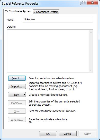


11 Transforming Between Coordinate Systems
12 Transforming Between Coordinate Systems At this point, ARC does the transformation, and when it finishes, it automatically loads it into the data view.which is BAD!! Because, these are two totally different coordinate systems. So, one has to remove the UTM layer and then right click on the GEO layer and select Zoom to Layer


13 Export Layer/Shapefile to KMZ file Double clicking this file will invoke GoogleEarth, which zooms to the location of the points. At this, time you can change symbology as you wish.

14 Export Layer/Shapefile to KMZ file

 We can use ArcMAP s Georeferencing function to")

15 Georeferencing an Image By establishing Ground Control Points using a GPS receiver for readily identifiable features (road intersections etc.) We can use ArcMAP s Georeferencing function to rectify/register the image to Earth coords. Is this photo tilted? Gradual topographic variation? Can you rely on photo-measured bearings or azimuths?
. I then scanned the image and saved it as a JPG file.")
16 Georeferencing an Image: An Example I traveled around ISU colleting GCPs using a Trimble GPS. I marked the location of each GCP on the photo while in the field (yellow dots). I then scanned the image and saved it as a JPG file. Notice the image is a little crooked, but that doesn t matter! GCP = Ground Control Point

17 Georeferencing an Image First display the GCP point file Then, the scanned image file Notice you can t see the image This is because it has no real coordinates. This is unlike the images you have downloaded in the past that have coords, but may be missing projection info. Go to Georeferencing tool and select Fit to Display Now, you can see the raw image and the misaligned GCPs.

 to fit these two point locations the fit is still poor. keep going, 8 more!")
18 Georeferencing an Image Now we link the GCP s in the POINT file to the yellow points I marked on the map. Under Georeferencing, select Add Control Points icon and start linking marked points to the corresponding GCP After the first link is made the whole image shifts so that the first field mark is now directly over the corresponding GCP The rest are still way off After the second link is made, the whole image is squeezed (or stretched) to fit these two point locations the fit is still poor. keep going, 8 more! Each time the fit is a little better. 2 nd Click 1 st Click


19 Georeferencing an Image Click and drag it over the point.unclick to zoom in, and then resume work
. Now, check to see how good the fit is by using the View Link Table icon What is RMS error (RMSE)?")
20 Georeferencing an Image After all links are made, the image is now oriented correctly and has the correct aspect ratio (shape). Now, check to see how good the fit is by using the View Link Table icon What is RMS error (RMSE)?
 (ERROR) 2 3 9 5 25 8 64 7 49")


21 Root Mean Squared Error RMSE Residual ERROR (Estimated True) (ERROR) RMSE = RMSE = error 2 N = 6.062m ArcMAP Georeferencing Tool Example Squared = = m


22 Georeferencing an Image 3 rd order polynomial fit RMSE = WOW!! What do you think went wrong? Minimum number or GCPs = (t + 1)(t + 2) 2 t = order of transformation 1 st order = 3 min 2 nd order = 6 min 3 rd order = 10 min We had the min 10 points, but distribution was bad!!


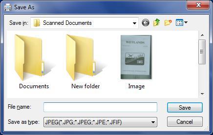
23 Final Task Rectify When your RMSE looks good, galvanize this fit by clicking. Update Georeferencing and then Rectify which invokes the Save As window to set up rectification options


24 DONE!
25 Wednesday

26 Distortion & Aerial Photography Why are aerial photographs prone to displacement propblems? That is, what one thing causes them to misrepresent true ground positions? Remember the vertical pencil example..


 12000 = 0.")
 farther away from nadir Displacement d")
27 To Refresh Your Memory on Displacement. Measurements based on Photo # 30 Scale 1:24100 H = Suburb NADIR E = h sub = NADIR E = River Displacement: d = rh H E = h riv = r riv nadir to river * 0.2 = 2.63 r sub nadir to suburb * 0.2 = 3.73 Actual Actual d riv = r riv h riv H nadir = 2.63" ( ) = " Correct map position (GD = 8.75 ) farther away from nadir Displacement d sub = r sub h sub H nadir = 3.73" ( ) Correct map position (GD= 37 ) closer to nadir = "
 ABOVE MSL (Feet) Flying Altitude above MSL A = 10890 feet 250 x 250 meter grid of DEM data 411.7 409.4 405.6 403.1 400.4 397.8 394.9 393.6 391.9 388.9 386.5 383.7 377.4 368.")
28 Scale Change is Proportional to Flying Height Terrain height at NADIR is often known. DEM used to visualize scale variation elsewhere. Camera Focal Length (CFL) f = 8.25 inch feet ELEVATION (E) ABOVE MSL (Feet) Flying Altitude above MSL A = feet 250 x 250 meter grid of DEM data PSR PSR = = (A (A-E) - / f / = f = (when E = 0) (when E = 0) Multiple Point Scales in one Photo (Assuming vertical photography) 1 : 15,315 H = A-E 1 : 15,239 A = altitude E = terrain elev
.")
29 National Map Accuracy Standards (NMAS) Initiated in 1937 by American Society of Photogrammetry & Remote Sensing NMAS adopted by U.S. Bureau of the Budget in 1941 Ensures accuracy of both location & elevation for all Federal agencies that produce map products. For maps on publication scales larger than 1:20,000, no more than 10% of points tested can be in error by more than 1/30 th of an inch (0.033 ). Smaller than 1:20,000, this is set to 1/50 th of an inch (0.02 ). For USGS 7.5-minute topoquads (1:24,000): HORIZONTAL 90% of all points tested must be within 1/50 th of an inch (0.05 cm) GD = 40 feet VERTICAL 90% of all points tested must be within ½ a contour interval (contours = 10 ) 5 feet All Federall puplished maps will state: This map complies with National Map Accuracy Standards, and whether it is an enlargement from a particular scale.
30 Estimating Horizontal Map Accuracy on a Photo Say you have a vertical, aerial photograph and you wish to know if you can get away with treating the photo like a map. That is, will photo measurements conform to some expected level of accuracy (e.g., project-level or NMAS)? Example: Frame is a 9 x 9 CIR photo PSR = 25600; flying height (H) = 12,800 ; focal length (f) = 0.5 You know the greatest difference in elevation (h) is ~10 ft. above & 160 ft. below PP. Largest single-photo parallax (r), or distance from PP to some hill/valley, is ~4 For an elevation difference of 160 ft. displacement is: d" = rh H d = 4" = 0.05 At a PSR of 25600, that is a GD error of: 0.05" " = /50 th of an inch = /12 = Should not do it! Impact on area calculations would be: PSR = = 25, 280 PSR = = 24, acres/square inch VS acres/square inch
 Rarely occurs in just one direction (commonly both X & Y) The")


 by simple")

31 Photo Perspective Has Problems Position Displacement & Scale Variation Tilt (camera/aircraft) Rarely occurs in just one direction (commonly both X & Y) The farther the object is away from the camera the greater the displacement. Scale change is uniform in direction of tilt. Scales constant along lines parallel to tilt. Terrain/Topography Effects are similar to tilt Ground is tilted instead of the camera Displacement effects are directly proportional to terrain complexity In Iowa, terrain change is generally slight & gradual easier to account for (model) by simple rectification using evenly distributed Ground Control Points (GCPs) per photo. As terrain becomes more complex, it is nearly impossible to collect enough GCPs to model (1 st, 2 nd, 3 rd order ) the effects of displacement on true pixel locations. Need a different process.
32 Photo Perspective vs. Orthographic Perspective Single-point Photo Perspective Orthographic Perspective? Variable scale & displacement Constant scale & no displacement

33 Digital Orthophotos Conventional aerial photographs contain image distortions caused by the tilting of the camera and terrain relief. The process of orthorectification removes these distortions and creates an orthophoto an image that looks like an aerial photograph yet has the uniform scale and planimetric accuracy of a map. The first orhtophotos were produce in California in 1965 using an analog process basically triangulation from multiple perspectives. Find true positions for numerous positions via triangulation from 2 or more photos, then reproject onto a new negative. T-64 Orthophotoscope, first instrument used for analog production of orthophotos


34 Digital Orthophotos Triangulation Process Original Image of a roof and the building s base in red Multiple views enable triangulation of true position of roof outline Corrected orthoimage of roof top position over its base

35 Aerial Photograph vs. Orthophoto

, and aircraft pitch, roll, and yaw amounts are known, then these parameters can be used with a DEM")

36 Orthorectification Using a Digital Elevation Model (DEM) Collecting some ground control points to account for simple 1 st or 2 nd order misalignments to Earth coordinates is a relatively simple task. Modern orthorectification requires use of a detailed DEM and sophisticated software If flying height above terrain (H), camera focal length (f), and aircraft pitch, roll, and yaw amounts are known, then these parameters can be used with a DEM to accurately model photo displacements using triangular irregular networks (TINs). Resulting displacement models producing thousands of uniformly distributed GCPs for the unrectified photo. Transforms photo from single point perspective to multi-point perspective ORTHOGRAPHIC perspective.


37 Microsoft s Global Ortho Program UltraCam-G Sensor flown at H = 5000 m (16,400 ft.) Automated Color Balancing Before After Minimum absolute positional accuracy requirements by land class. Specular Reflection Automated Removal Before After Ortho production then combines this with a detailed, LIDAR-based, DEM to correct tilt & terrain distortions.


38 Digital Orthophotos The Key Points to Remember What is the difference between an aerial photograph and an orthophoto? A conventional perspective aerial photograph contains image displacements caused by camera tilt and variable terrain Aerial photos do not have a uniform scale. Hence, you cannot measure distances reliably on an aerial photograph like you can on a map. Vertical aerial photos (single-point perspective) are not maps. An orthophoto is a uniform-scale photograph..it is a photographic map, and measurements can be made on it like other maps. Therefore, orthophotos may serve as base maps onto which other map information may be overlaid or derived.
39 Orthophoto Design Considerations End users of digital orthophotos have very robust hardware & sophisticated software to view and manipulate orthophoto images. Requires the ability to view selected image features & perform analysis such as relative distance, area, change analysis etc. To meet these demands, proper design of an orthophoto is imperative. Design should consider the following factors: 1. Expected use of the orthophotos & smallest feature to be analyses Urban feature mapping vs. forest cover type mapping 2. Accuracy requirements (relative and feature) X,Y ground distance vs. feature area preservation 3. Equipment, data, and processes used to generate the orthophotos Camera vs. sensor image vs. DEM resolution Transformation/rectification processes used


40 Scanning Images in RM Click START icon Click 1 st option Type in SCAN

41 Scanning Images in RM 241

42 Scanning Images in RM 241
Measurement of Direction: Bearing vs. Azimuth
 Week 5 Monday Measurement of Direction: Bearing vs. Azimuth Bearing Is an angle of 90 o or less Measured from either North or South in easterly & westerly directions. North 22 o West, South 89 o West,
Geometric Rectification of Remote Sensing Images
 Geometric Rectification of Remote Sensing Images Airborne TerrestriaL Applications Sensor (ATLAS) Nine flight paths were recorded over the city of Providence. 1 True color ATLAS image (bands 4, 2, 1 in
Introduction Photogrammetry Photos light Gramma drawing Metron measure Basic Definition The art and science of obtaining reliable measurements by mean
 Photogrammetry Review Neil King King and Associates Testing is an art Introduction Read the question Re-Read Read The question What is being asked Answer what is being asked Be in the know Exercise the
Photogrammetry: DTM Extraction & Editing
 Photogrammetry: DTM Extraction & Editing How can one determine the x, y, and z of a location? Approaches to DTM Extraction Ground surveying Digitized topographic maps Traditional photogrammetry Hardcopy
Georeferencing in ArcGIS
 Georeferencing in ArcGIS Georeferencing In order to position images on the surface of the earth, they need to be georeferenced. Images are georeferenced by linking unreferenced features in the image with
Overview. Image Geometric Correction. LA502 Special Studies Remote Sensing. Why Geometric Correction?
 LA502 Special Studies Remote Sensing Image Geometric Correction Department of Landscape Architecture Faculty of Environmental Design King AbdulAziz University Room 103 Overview Image rectification Geometric
LiDAR & Orthophoto Data Report
 LiDAR & Orthophoto Data Report Tofino Flood Plain Mapping Data collected and prepared for: District of Tofino, BC 121 3 rd Street Tofino, BC V0R 2Z0 Eagle Mapping Ltd. #201 2071 Kingsway Ave Port Coquitlam,
Training i Course Remote Sensing Basic Theory & Image Processing Methods September 2011
 Training i Course Remote Sensing Basic Theory & Image Processing Methods 19 23 September 2011 Geometric Operations Michiel Damen (September 2011) damen@itc.nl ITC FACULTY OF GEO-INFORMATION SCIENCE AND
2. POINT CLOUD DATA PROCESSING
 Point Cloud Generation from suas-mounted iphone Imagery: Performance Analysis A. D. Ladai, J. Miller Towill, Inc., 2300 Clayton Road, Suite 1200, Concord, CA 94520-2176, USA - (andras.ladai, jeffrey.miller)@towill.com
Iowa Department of Transportation Office of Design. Photogrammetric Mapping Specifications
 Iowa Department of Transportation Office of Design Photogrammetric Mapping Specifications March 2015 1 Purpose of Manual These Specifications for Photogrammetric Mapping define the standards and general
Geometry of Aerial photogrammetry. Panu Srestasathiern, PhD. Researcher Geo-Informatics and Space Technology Development Agency (Public Organization)
") Geometry of Aerial photogrammetry Panu Srestasathiern, PhD. Researcher Geo-Informatics and Space Technology Development Agency (Public Organization) Image formation - Recap The geometry of imaging system
Geometry of Aerial photogrammetry Panu Srestasathiern, PhD. Researcher Geo-Informatics and Space Technology Development Agency (Public Organization) Image formation - Recap The geometry of imaging system
Low-Cost Orthophoto Production Using OrthoMapper Software
 Low-Cost Orthophoto Production Using OrthoMapper Software Rick Day Penn State Cooperative Extension, Geospatial Technology Program, RGIS-Chesapeake Air Photos Historical air photos are available from a
Tutorial (Beginner level): Orthomosaic and DEM Generation with Agisoft PhotoScan Pro 1.3 (with Ground Control Points)
: Orthomosaic and DEM Generation with Agisoft PhotoScan Pro 1.3 (with Ground Control Points)") Tutorial (Beginner level): Orthomosaic and DEM Generation with Agisoft PhotoScan Pro 1.3 (with Ground Control Points) Overview Agisoft PhotoScan Professional allows to generate georeferenced dense point
Tutorial (Beginner level): Orthomosaic and DEM Generation with Agisoft PhotoScan Pro 1.3 (with Ground Control Points) Overview Agisoft PhotoScan Professional allows to generate georeferenced dense point
Aerial Photo Rectification
 Aerial Photo Rectification ERDAS Imagine 2016 Description: We will be using ERDAS Imagine to georeference aerial photos to a DOQ image. We will try to achieve this with a total RMS (root mean square) error
Files Used in this Tutorial
 RPC Orthorectification Tutorial In this tutorial, you will use ground control points (GCPs), an orthorectified reference image, and a digital elevation model (DEM) to orthorectify an OrbView-3 scene that
MONO-IMAGE INTERSECTION FOR ORTHOIMAGE REVISION
 MONO-IMAGE INTERSECTION FOR ORTHOIMAGE REVISION Mohamed Ibrahim Zahran Associate Professor of Surveying and Photogrammetry Faculty of Engineering at Shoubra, Benha University ABSTRACT This research addresses
Photogrammetry: DTM Extraction & Editing
 Photogrammetry: DTM Extraction & Editing Review of terms Vertical aerial photograph Perspective center Exposure station Fiducial marks Principle point Air base (Exposure Station) Digital Photogrammetry:
POSITIONING A PIXEL IN A COORDINATE SYSTEM
 GEOREFERENCING AND GEOCODING EARTH OBSERVATION IMAGES GABRIEL PARODI STUDY MATERIAL: PRINCIPLES OF REMOTE SENSING AN INTRODUCTORY TEXTBOOK CHAPTER 6 POSITIONING A PIXEL IN A COORDINATE SYSTEM The essential
Chapters 1-4: Summary
 Chapters 1-4: Summary So far, we have been investigating the image acquisition process. Chapter 1: General introduction Chapter 2: Radiation source and properties Chapter 3: Radiation interaction with
This will display various panes in a window.
 Map Map projections in ArcMap can be a bit confusing, because the program often automatically reprojects data for display, and there are a ways to permanently project data to new data sets. This describes
LAB #7 Creating TIN and 3D scenes (ArcScene) GISC, UNIVERSITY OF CALIFORNIA BERKELEY
 GISC, UNIVERSITY OF CALIFORNIA BERKELEY") LAB #7 Creating TIN and 3D scenes (ArcScene) GISC, UNIVERSITY OF CALIFORNIA BERKELEY The purpose of this laboratory is to introduce and explore surface data analysis using a vector data model: TIN. We
LAB #7 Creating TIN and 3D scenes (ArcScene) GISC, UNIVERSITY OF CALIFORNIA BERKELEY The purpose of this laboratory is to introduce and explore surface data analysis using a vector data model: TIN. We
٥...: (Picture element) Pixel ٧...:
 Pixel ٧...:") ( RS ) : : / : : - ٣... : ٣...: ٤...: ٥...: (Picture element) Pixel ٥...: ٧...: ١٠... : Geo Tiff ١٨... : ١٩... : DEM ٢٨...: ٢ :.. " " RS. :.. Kosmos Land Sat. : : RS :. : (Land Use) :( Change detection
( RS ) : : / : : - ٣... : ٣...: ٤...: ٥...: (Picture element) Pixel ٥...: ٧...: ١٠... : Geo Tiff ١٨... : ١٩... : DEM ٢٨...: ٢ :.. " " RS. :.. Kosmos Land Sat. : : RS :. : (Land Use) :( Change detection
TRAINING MATERIAL HOW TO OPTIMIZE ACCURACY WITH CORRELATOR3D
 TRAINING MATERIAL WITH CORRELATOR3D Page2 Contents 1. UNDERSTANDING INPUT DATA REQUIREMENTS... 4 1.1 What is Aerial Triangulation?... 4 1.2 Recommended Flight Configuration... 4 1.3 Data Requirements for
LPS Project Manager User s Guide. November 2009
 LPS Project Manager User s Guide November 2009 Copyright 2009 ERDAS, Inc. All rights reserved. Printed in the United States of America. The information contained in this document is the exclusive property
I. An Intro to ArcMap Version 9.3 and 10. 1) Arc Map is basically a build your own Google map
 Arc Map is basically a build your own Google map") I. An Intro to ArcMap Version 9.3 and 10 What is Arc Map? 1) Arc Map is basically a build your own Google map a. Display and manage geo-spatial data (maps, images, points that have a geographic location)
I. An Intro to ArcMap Version 9.3 and 10 What is Arc Map? 1) Arc Map is basically a build your own Google map a. Display and manage geo-spatial data (maps, images, points that have a geographic location)
University of Technology Building & Construction Department / Remote Sensing & GIS lecture
 5. Corrections 5.1 Introduction 5.2 Radiometric Correction 5.3 Geometric corrections 5.3.1 Systematic distortions 5.3.2 Nonsystematic distortions 5.4 Image Rectification 5.5 Ground Control Points (GCPs)
Contents of Lecture. Surface (Terrain) Data Models. Terrain Surface Representation. Sampling in Surface Model DEM
 Data Models. Terrain Surface Representation. Sampling in Surface Model DEM") Lecture 13: Advanced Data Models: Terrain mapping and Analysis Contents of Lecture Surface Data Models DEM GRID Model TIN Model Visibility Analysis Geography 373 Spring, 2006 Changjoo Kim 11/29/2006 1
Lecture 13: Advanced Data Models: Terrain mapping and Analysis Contents of Lecture Surface Data Models DEM GRID Model TIN Model Visibility Analysis Geography 373 Spring, 2006 Changjoo Kim 11/29/2006 1
Files Used in this Tutorial
 RPC Orthorectification Tutorial In this tutorial, you will use ground control points (GCPs), an orthorectified reference image, and a digital elevation model (DEM) to orthorectify an OrbView-3 scene that
START>PROGRAMS>ARCGIS>
 Department of Urban Studies and Planning Spring 2006 Department of Architecture Site and Urban Systems Planning 11.304J / 4.255J GIS EXERCISE 2 Objectives: To generate the following maps using ArcGIS Software:
Geometric Correction of Imagery
 Geometric Correction of Imagery Geometric Correction of Imagery Present by: Dr.Weerakaset Suanpaga D.Eng(RS&GIS) The intent is to compensate for the distortions introduced by a variety of factors, so that
Lab 5: Georeferencing, Digitization, and Processing
 Lab 5: Georeferencing, Digitization, and Processing Purpose: An introduction to georeferencing images, practice digitizing, and combine lesson up to this point. To Do: Register a scanned image, digitize
LIDAR MAPPING FACT SHEET
 1. LIDAR THEORY What is lidar? Lidar is an acronym for light detection and ranging. In the mapping industry, this term is used to describe an airborne laser profiling system that produces location and
Introduction to LiDAR
 Introduction to LiDAR Our goals here are to introduce you to LiDAR data. LiDAR data is becoming common, provides ground, building, and vegetation heights at high accuracy and detail, and is available statewide.
Technical Considerations and Best Practices in Imagery and LiDAR Project Procurement
 Technical Considerations and Best Practices in Imagery and LiDAR Project Procurement Presented to the 2014 WV GIS Conference By Brad Arshat, CP, EIT Date: June 4, 2014 Project Accuracy A critical decision
Tutorial (Beginner level): Orthomosaic and DEM Generation with Agisoft PhotoScan Pro 1.3 (without Ground Control Points)
: Orthomosaic and DEM Generation with Agisoft PhotoScan Pro 1.3 (without Ground Control Points)") Tutorial (Beginner level): Orthomosaic and DEM Generation with Agisoft PhotoScan Pro 1.3 (without Ground Control Points) Overview Agisoft PhotoScan Professional allows to generate georeferenced dense point
Tutorial (Beginner level): Orthomosaic and DEM Generation with Agisoft PhotoScan Pro 1.3 (without Ground Control Points) Overview Agisoft PhotoScan Professional allows to generate georeferenced dense point
KEY WORDS: IKONOS, Orthophotos, Relief Displacement, Affine Transformation
 GRATIO OF DIGITAL ORTHOPHOTOS FROM IKOOS GO IMAGS Liang-Chien Chen and Chiu-Yueh Lo Center for Space and Remote Sensing Research. ational Central University Tel: 886-3-47151 xt.76 Fax: 886-3-455535 lcchen@csrsr.ncu.edu.tw
Geometric Accuracy Evaluation, DEM Generation and Validation for SPOT-5 Level 1B Stereo Scene
 Geometric Accuracy Evaluation, DEM Generation and Validation for SPOT-5 Level 1B Stereo Scene Buyuksalih, G.*, Oruc, M.*, Topan, H.*,.*, Jacobsen, K.** * Karaelmas University Zonguldak, Turkey **University
Convert Local Coordinate Systems to Standard Coordinate Systems
 BENTLEY SYSTEMS, INC. Convert Local Coordinate Systems to Standard Coordinate Systems Using 2D Conformal Transformation in MicroStation V8i and Bentley Map V8i Jim McCoy P.E. and Alain Robert 4/18/2012
Geometric Correction
 CEE 6150: Digital Image Processing Geometric Correction 1 Sources of Distortion Sensor Characteristics optical distortion aspect ratio non-linear mirror velocity detector geometry & scanning sequence Viewing
Main concepts of ILWIS 3.0
 CHAPTER 2 Main concepts of ILWIS 3.0 In chapter one, Introduction to ILWIS, you started with ILWIS, and learned the basics of the user interface. This chapter presents some key concepts of ILWIS. In section
Orthorectification Using Rational Polynomials
 R P C O R T H O Tutorial Orthorectification Using Rational Polynomials Orthorectification Using Rational Polynomials with TNTmips page 1 Before Getting Started You can orthorectify certain types of satellite
Lecture 4. Image Georeferencing, Accuracy and Precision, File Geodatabase
 Lecture 4 Image Georeferencing, Accuracy and Precision, File Geodatabase Tomislav Sapic GIS Technologist Faculty of Natural Resources Management Lakehead University Why Georeference? Images of the surface
Orthophotography and LiDAR Terrain Data Collection Rogue River, Oregon Final Report
 Orthophotography and LiDAR Terrain Data Collection Rogue River, Oregon Final Report Prepared by Sky Research, Inc. 445 Dead Indian Memorial Road Ashland, OR 97520 Prepared for Rogue Valley Council of Governments
GIS Workshop Spring 2016
 1/ 14 GIS Geographic Information System. An integrated collection of computer software and data used to view and manage information about geographic places, analyze spatial relationships, and model spatial
Exercise 4: Import Tabular GPS Data and Digitizing
 Exercise 4: Import Tabular GPS Data and Digitizing You can create NEW GIS data layers by digitizing on screen with an aerial photograph or other image as a back-drop. You can also digitize using imported
Using ArcGIS Server Data to Assist in Planimetric Update Process. Jim Stout - IMAGIS Rick Hammond Woolpert
 Using ArcGIS Server Data to Assist in Planimetric Update Process Jim Stout - IMAGIS Rick Hammond Woolpert Using ArcGIS Server Data to Assist in Planimetric Update Process Jim Stout - IMAGIS Rick Hammond
GSSHA WMS Basics Loading DEMs, Contour Options, Images, and Projection Systems
 v. 10.0 WMS 10.0 Tutorial GSSHA WMS Basics Loading DEMs, Contour Options, Images, and Projection Systems Learn how to work with DEMs and images and to convert between projection systems in the WMS interface
Digital Elevation Models
 Digital Elevation Models National Elevation Dataset 1 Data Sets US DEM series 7.5, 30, 1 o for conterminous US 7.5, 15 for Alaska US National Elevation Data (NED) GTOPO30 Global Land One-kilometer Base
An Introduction to Geographic Information Systems (GIS) using ArcGIS 9.2
 using ArcGIS 9.2") An Introduction to Geographic Information Systems (GIS) using ArcGIS 9.2 by Marcel Fortin, GIS and Map Librarian, University of Toronto Libraries, 2009 gis.maps@utoronto.ca http://www.library.utoronto.ca/maplib/
An Introduction to Geographic Information Systems (GIS) using ArcGIS 9.2 by Marcel Fortin, GIS and Map Librarian, University of Toronto Libraries, 2009 gis.maps@utoronto.ca http://www.library.utoronto.ca/maplib/
Purpose: To explore the raster grid and vector map element concepts in GIS.
 GIS INTRODUCTION TO RASTER GRIDS AND VECTOR MAP ELEMENTS c:wou:nssi:vecrasex.wpd Purpose: To explore the raster grid and vector map element concepts in GIS. PART A. RASTER GRID NETWORKS Task A- Examine
N.J.P.L.S. An Introduction to LiDAR Concepts and Applications
 N.J.P.L.S. An Introduction to LiDAR Concepts and Applications Presentation Outline LIDAR Data Capture Advantages of Lidar Technology Basics Intensity and Multiple Returns Lidar Accuracy Airborne Laser
RECOMMENDATION ITU-R P DIGITAL TOPOGRAPHIC DATABASES FOR PROPAGATION STUDIES. (Question ITU-R 202/3)
") Rec. ITU-R P.1058-1 1 RECOMMENDATION ITU-R P.1058-1 DIGITAL TOPOGRAPHIC DATABASES FOR PROPAGATION STUDIES (Question ITU-R 202/3) Rec. ITU-R P.1058-1 (1994-1997) The ITU Radiocommunication Assembly, considering
Rec. ITU-R P.1058-1 1 RECOMMENDATION ITU-R P.1058-1 DIGITAL TOPOGRAPHIC DATABASES FOR PROPAGATION STUDIES (Question ITU-R 202/3) Rec. ITU-R P.1058-1 (1994-1997) The ITU Radiocommunication Assembly, considering
Lecture 5. Relief displacement. Parallax. Monoscopic and stereoscopic height measurement. Photo Project. Soft-copy Photogrammetry.
 NRMT 2270, Photogrammetry/Remote Sensing Lecture 5 Relief displacement. Parallax. Monoscopic and stereoscopic height measurement. Photo Project. Soft-copy Photogrammetry. Tomislav Sapic GIS Technologist
COORDINATE TRANSFORMATION. Lecture 6
 COORDINATE TRANSFORMATION Lecture 6 SGU 1053 SURVEY COMPUTATION 1 Introduction Geomatic professional are mostly confronted in their work with transformations from one two/three-dimensional coordinate system
Exercise #5b - Geometric Correction of Image Data
 Exercise #5b - Geometric Correction of Image Data 5.6 Geocoding or Registration of geometrically uncorrected image data 5.7 Resampling 5.8 The Ukrainian coordinate system 5.9 Selecting Ground Control Points
CHAPTER 10. Digital Mapping and Earthwork
 CHAPTER 10 Digital Mapping and Earthwork www.terrainmap.com/rm22.html CE 316 March 2012 348 10.1 Introduction 349 10.2 Single Images 10.2.1 Rectified Photograph With a single photograph, X,Y data can be
Journal Online Jaringan COT POLIPD (JOJAPS) Accuracy Assessment of Height Coordinate Using Unmanned Aerial Vehicle Images Based On Leveling Height
 Accuracy Assessment of Height Coordinate Using Unmanned Aerial Vehicle Images Based On Leveling Height") JOJAPS eissn 2504-8457 Abstract Journal Online Jaringan COT POLIPD (JOJAPS) Accuracy Assessment of Height Coordinate Using Unmanned Aerial Vehicle Images Based On Leveling Height Syamsul Anuar Bin Abu
JOJAPS eissn 2504-8457 Abstract Journal Online Jaringan COT POLIPD (JOJAPS) Accuracy Assessment of Height Coordinate Using Unmanned Aerial Vehicle Images Based On Leveling Height Syamsul Anuar Bin Abu
Orthorectification Using Rational Polynomials
 R P C O R T H O Tutorial Orthorectification Using Rational Polynomials Orthorectification Using Rational Polynomials with TNTmips page 1 Before Getting Started You can orthorectify images that have a mathematical
INTRODUCTION TO GIS WORKSHOP EXERCISE
 111 Mulford Hall, College of Natural Resources, UC Berkeley (510) 643-4539 INTRODUCTION TO GIS WORKSHOP EXERCISE This exercise is a survey of some GIS and spatial analysis tools for ecological and natural
3. Map Overlay and Digitizing
 3. Map Overlay and Digitizing 3.1 Opening Map Files NavviewW/SprayView supports digital map files in ShapeFile format from ArcView, DXF format from AutoCAD, MRK format from AG-NAV, Bitmap and JPEG formats
GIS in agriculture scale farm level - used in agricultural applications - managing crop yields, monitoring crop rotation techniques, and estimate
 Types of Input GIS in agriculture scale farm level - used in agricultural applications - managing crop yields, monitoring crop rotation techniques, and estimate soil loss from individual farms or agricultural
Light Detection and Ranging (LiDAR)
") Light Detection and Ranging (LiDAR) http://code.google.com/creative/radiohead/ Types of aerial sensors passive active 1 Active sensors for mapping terrain Radar transmits microwaves in pulses determines
Light Detection and Ranging (LiDAR) http://code.google.com/creative/radiohead/ Types of aerial sensors passive active 1 Active sensors for mapping terrain Radar transmits microwaves in pulses determines
CHAPTER 5 DIGITAL ELEVATION MODEL AND 3D VISUALIZATION
 CHAPTER 5 DIGITAL ELEVATION MODEL AND 3D VISUALIZATION A digital elevation model (DEM) is a digital model or 3D representation of a terrain's surface. A DEM can be represented as a raster (a grid of squares,
ACCURACY OF DIGITAL ORTHOPHOTOS FROM HIGH RESOLUTION SPACE IMAGERY
 ACCURACY OF DIGITAL ORTHOPHOTOS FROM HIGH RESOLUTION SPACE IMAGERY Jacobsen, K.*, Passini, R. ** * University of Hannover, Germany ** BAE Systems ADR, Pennsauken, NJ, USA acobsen@ipi.uni-hannover.de rpassini@adrinc.com
Objectives Learn how to work with projections in GMS, and how to combine data from different coordinate systems into the same GMS project.
 v. 10.2 GMS 10.2 Tutorial Working with map projections in GMS Objectives Learn how to work with projections in GMS, and how to combine data from different coordinate systems into the same GMS project.
Raster Images Processing
 Software PHOTOMOD Module PHOTOMOD VectOr Raster Images Processing Racurs, Moscow, 2009 PHOTOMOD CONTENTS 1. Raster processing in PHOTOMOD VectOr...3 1.1. Raster map...3 1.2. Raster data conversion...4
Import, view, edit, convert, and digitize triangulated irregular networks
 v. 10.1 WMS 10.1 Tutorial Import, view, edit, convert, and digitize triangulated irregular networks Objectives Import survey data in an XYZ format. Digitize elevation points using contour imagery. Edit
THE INTERIOR AND EXTERIOR CALIBRATION FOR ULTRACAM D
 THE INTERIOR AND EXTERIOR CALIBRATION FOR ULTRACAM D K. S. Qtaishat, M. J. Smith, D. W. G. Park Civil and Environment Engineering Department, Mu ta, University, Mu ta, Karak, Jordan, 61710 khaldoun_q@hotamil.com
Image georeferencing is the process of developing a model to transform from pixel coordinates into GIS coordinates such as meters on the ground.
 Image georeferencing is the process of developing a model to transform from pixel coordinates into GIS coordinates such as meters on the ground. Image rectification is the process of using your georeferencing
MODULE 1 BASIC LIDAR TECHNIQUES
 MODULE SCENARIO One of the first tasks a geographic information systems (GIS) department using lidar data should perform is to check the quality of the data delivered by the data provider. The department
THE FUTURE OF STATE PLANE COORDINATES AT ODOT
 THE FUTURE OF STATE PLANE COORDINATES AT ODOT BY: RAY FOOS P.S. AND BRIAN MEADE P.S. THE OHIO DEPARTMENT OF TRANSPORTATION WORKING WITH STATE PLANE COORDINATES OR HOW TO MAKE THE EARTH FLAT SURVEYORS AND
Course Outline (1) #6 Data Acquisition for Built Environment. Fumio YAMAZAKI
 #6 Data Acquisition for Built Environment. Fumio YAMAZAKI") AT09.98 Applied GIS and Remote Sensing for Disaster Mitigation #6 Data Acquisition for Built Environment 9 October, 2002 Fumio YAMAZAKI yamazaki@ait.ac.th http://www.star.ait.ac.th/~yamazaki/ Course Outline
AT09.98 Applied GIS and Remote Sensing for Disaster Mitigation #6 Data Acquisition for Built Environment 9 October, 2002 Fumio YAMAZAKI yamazaki@ait.ac.th http://www.star.ait.ac.th/~yamazaki/ Course Outline
Geology & Geophysics REU GPS/GIS 1-day workshop handout #3: Working with data in ArcGIS
 Geology & Geophysics REU GPS/GIS 1-day workshop handout #3: Working with data in ArcGIS In this lab you ll start to use some basic ArcGIS routines to display your data. These include overlaying data on
DEVELOPMENT OF ORIENTATION AND DEM/ORTHOIMAGE GENERATION PROGRAM FOR ALOS PRISM
 DEVELOPMENT OF ORIENTATION AND DEM/ORTHOIMAGE GENERATION PROGRAM FOR ALOS PRISM Izumi KAMIYA Geographical Survey Institute 1, Kitasato, Tsukuba 305-0811 Japan Tel: (81)-29-864-5944 Fax: (81)-29-864-2655
Specify Projection Customizing Projection Changing Projection
 Specify Projection Customizing Projection Changing Projection Click the Projection button FYI: To select zone pls. see in next slide From the View Menu, Choose Properties If a projection has already been
Central Coast LIDAR Project, 2011 Delivery 1 QC Analysis LIDAR QC Report February 17 th, 2012
 O R E G O N D E P A R T M E N T O F G E O L O G Y A N D M I N E R A L I N D U S T R I E S OLC Central Coast Delivery 1 Acceptance Report. Department of Geology & Mineral Industries 800 NE Oregon St, Suite
GEOGRAPHIC INFORMATION SYSTEMS Lecture 25: 3D Analyst
 GEOGRAPHIC INFORMATION SYSTEMS Lecture 25: 3D Analyst 3D Analyst - 3D Analyst is an ArcGIS extension designed to work with TIN data (triangulated irregular network) - many of the tools in 3D Analyst also
ACCURACY COMPARISON OF VHR SYSTEMATIC-ORTHO SATELLITE IMAGERIES AGAINST VHR ORTHORECTIFIED IMAGERIES USING GCP
 ACCURACY COMPARISON OF VHR SYSTEMATIC-ORTHO SATELLITE IMAGERIES AGAINST VHR ORTHORECTIFIED IMAGERIES USING GCP E. Widyaningrum a, M. Fajari a, J. Octariady a * a Geospatial Information Agency (BIG), Cibinong,
High resolution survey and orthophoto project of the Dosso-Gaya region in the Republic of Niger. by Tim Leary, Woolpert Inc.
 High resolution survey and orthophoto project of the Dosso-Gaya region in the Republic of Niger by Tim Leary, Woolpert Inc. Geospatial Solutions Photogrammetry & Remote Sensing LiDAR Professional Surveying
Alaska Department of Transportation Roads to Resources Project LiDAR & Imagery Quality Assurance Report Juneau Access South Corridor
 Alaska Department of Transportation Roads to Resources Project LiDAR & Imagery Quality Assurance Report Juneau Access South Corridor Written by Rick Guritz Alaska Satellite Facility Nov. 24, 2015 Contents
Lecture 4: Digital Elevation Models
 Lecture 4: Digital Elevation Models GEOG413/613 Dr. Anthony Jjumba 1 Digital Terrain Modeling Terms: DEM, DTM, DTEM, DSM, DHM not synonyms. The concepts they illustrate are different Digital Terrain Modeling
A Method to Create a Single Photon LiDAR based Hydro-flattened DEM
 A Method to Create a Single Photon LiDAR based Hydro-flattened DEM Sagar Deshpande 1 and Alper Yilmaz 2 1 Surveying Engineering, Ferris State University 2 Department of Civil, Environmental, and Geodetic
About LIDAR Data. What Are LIDAR Data? How LIDAR Data Are Collected
 1 of 6 10/7/2006 3:24 PM Project Overview Data Description GIS Tutorials Applications Coastal County Maps Data Tools Data Sets & Metadata Other Links About this CD-ROM Partners About LIDAR Data What Are
APPENDIX 13 TERRAIN NAVIGATOR PRO BASICS. Prepared by the Mapping and Marking Committee. Fifth Edition (Revised and Expanded) June 2014
 June 2014") APPENDIX 13 TERRAIN NAVIGATOR PRO BASICS Prepared by the Mapping and Marking Committee Fifth Edition (Revised and Expanded) June 2014 Published by the Oregon-California Trails Association P.O. Box 1019
APPENDIX 13 TERRAIN NAVIGATOR PRO BASICS Prepared by the Mapping and Marking Committee Fifth Edition (Revised and Expanded) June 2014 Published by the Oregon-California Trails Association P.O. Box 1019
Georeferencing & Spatial Adjustment
 Georeferencing & Spatial Adjustment Aligning Raster and Vector Data to the Real World Rotation Differential Scaling Distortion Skew Translation 1 The Problem How are geographically unregistered data, either
CLASSIFICATION OF NONPHOTOGRAPHIC REMOTE SENSORS
 CLASSIFICATION OF NONPHOTOGRAPHIC REMOTE SENSORS PASSIVE ACTIVE DIGITAL CAMERA THERMAL (e.g. TIMS) VIDEO CAMERA MULTI- SPECTRAL SCANNERS VISIBLE & NIR MICROWAVE HYPERSPECTRAL (e.g. AVIRIS) SLAR Real Aperture
Producing Ortho Imagery In ArcGIS. Hong Xu, Mingzhen Chen, Ringu Nalankal
 Producing Ortho Imagery In ArcGIS Hong Xu, Mingzhen Chen, Ringu Nalankal Agenda Ortho imagery in GIS ArcGIS ortho mapping solution Workflows - Satellite imagery - Digital aerial imagery - Scanned imagery
HIGH RESOLUTION DEMs AND ORTHO-IMAGE BASEMAPS FOR LOCAL GOVERNMENT APPLICATIONS
 HIGH RESOLUTION DEMs AND ORTHO-IMAGE BASEMAPS FOR LOCAL GOVERNMENT APPLICATIONS STATEMENT OF PROBLEM Digital Elevation Models (DEMs) are the digital representation of topographic and/or manmade features
Technical Specifications
 1 Contents INTRODUCTION...3 ABOUT THIS LAB...3 IMPORTANCE OF THIS MODULE...3 EXPORTING AND IMPORTING DATA...4 VIEWING PROJECTION INFORMATION...5...6 Assigning Projection...6 Reprojecting Data...7 CLIPPING/SUBSETTING...7
GIS OPERATION MANUAL
 GIS OPERATION MANUAL 1. Computer System Description Hardware Make Compaq Presario 5004 CPU AMD Athlon 1.1 Ghz Main Memory 640MB CD-ROM 52 X CD-RW 8 X HD 57GB Monitor 19 inch Video Adapter 16 Mb Nvidia
SPOT-1 stereo images taken from different orbits with one month difference
 DSM Generation Almost all HR sensors are stereo capable. Some can produce even triplettes within the same strip (facilitating multi-image matching). Mostly SPOT (1-5) used for stereo and Ikonos (in spite
Doc #: IDI06-11F Rev: 1.3 Issued: 22/02/18. Well Seeker PRO How To Guide Rev 1.3. Page 1 of 26
 Well Seeker PRO How To Guide Rev 1.3 Page 1 of 26 Contents 1.0 - Getting Started... 4 1.1 - Display... 4 2.0 - Creating a new Well... 5 2.1 - Unit Selection... 5 2.2 - New Instant Plan / Survey... 6 2.3
SMS v D Summary Table. SRH-2D Tutorial. Prerequisites. Requirements. Time. Objectives
 SMS v. 12.3 SRH-2D Tutorial Objectives Learn the process of making a summary table to compare the 2D hydraulic model results with 1D hydraulic model results. This tutorial introduces a method of presenting
Exercise 5: Import Tabular GPS Data and Digitizing
 Exercise 5: Import Tabular GPS Data and Digitizing You can create NEW GIS data layers by digitizing on screen with an aerial photograph or other image as a back-drop. You can also digitize using imported
Local Elevation Surface Modeling using GPS Derived Point Clouds. John G. Whitman, Jr.
 Local Elevation Surface Modeling using GPS Derived Point Clouds WhitmanJ2@myfairpoint.net Study Area Overview Topographic Background NAIP with Roads and Streams Public DEM Models of Study Area National
Georeferencing Imagery in ArcGIS 10.3.x
 Georeferencing Imagery in ArcGIS 10.3.x Georeferencing is the process of aligning imagery (maps, air photos, etc.) with spatial data such as point, lines or polygons (for example, roads and water bodies).
Lab 11: Terrain Analyses
 Lab 11: Terrain Analyses What You ll Learn: Basic terrain analysis functions, including watershed, viewshed, and profile processing. There is a mix of old and new functions used in this lab. We ll explain
[Youn *, 5(11): November 2018] ISSN DOI /zenodo Impact Factor
![[Youn *, 5(11): November 2018] ISSN DOI /zenodo Impact Factor](/thumbs/91/105079225.jpg "[Youn *, 5(11): November 2018] ISSN DOI /zenodo Impact Factor") GLOBAL JOURNAL OF ENGINEERING SCIENCE AND RESEARCHES AUTOMATIC EXTRACTING DEM FROM DSM WITH CONSECUTIVE MORPHOLOGICAL FILTERING Junhee Youn *1 & Tae-Hoon Kim 2 *1,2 Korea Institute of Civil Engineering
GLOBAL JOURNAL OF ENGINEERING SCIENCE AND RESEARCHES AUTOMATIC EXTRACTING DEM FROM DSM WITH CONSECUTIVE MORPHOLOGICAL FILTERING Junhee Youn *1 & Tae-Hoon Kim 2 *1,2 Korea Institute of Civil Engineering
SimActive and PhaseOne Workflow case study. By François Riendeau and Dr. Yuri Raizman Revision 1.0
 SimActive and PhaseOne Workflow case study By François Riendeau and Dr. Yuri Raizman Revision 1.0 Contents 1. Introduction... 2 1.1. Simactive... 2 1.2. PhaseOne Industrial... 2 2. Testing Procedure...
RIGTERSBLEEK - AALTEN 4 - B RB ENSCHEDE - THE NETHERLANDS
 RIGTERSBLEEK - AALTEN 4 - B17 7521 RB ENSCHEDE - THE NETHERLANDS Tel +31-53 4342001 - Fax +31 53 4302845 - Hot line +31 6 51363197 Email trackair@compuserve.com Internet http://www.trackair.com THE TRACKER