Chapter 2 HCS12 Assembly Language
|
|
|
- Alexandrina Hamilton
- 6 years ago
- Views:
Transcription


1 Chapter 2 HCS12 Assembly Language ECE 3120 Dr. Mohamed Mahmoud mmahmoud@tntech.edu
2 Outline 2.1 Assembly language program structure 2.2 Data transfer instructions 2.3 Arithmetic instructions 2.4 Branch and loop instructions 2.5 Shift and rotate instructions 2.6 Boolean logic instructions 2.7 Bit test and manipulate instructions 2.8 Stack 2.9 Subroutines
3 - Commands to the assembler 1- Assembler directives - Are not executed by the microcontroller are not converted to machine codes - Define program constants and reserve space for variable 2-1
4 1. Org (origin) - Tells the assembler where to place the next instruction/data in memory -Example: org $1000 ldab #$FF ;this instruction will be stored in memory starting from location $ dc.b (define constant byte), db (define byte), fcb (form constant byte) - Define the value of a byte or bytes that will be placed at a given location. -Example: org $800 array dc.b $11,$22,$33,$ $11 $22 $33 $
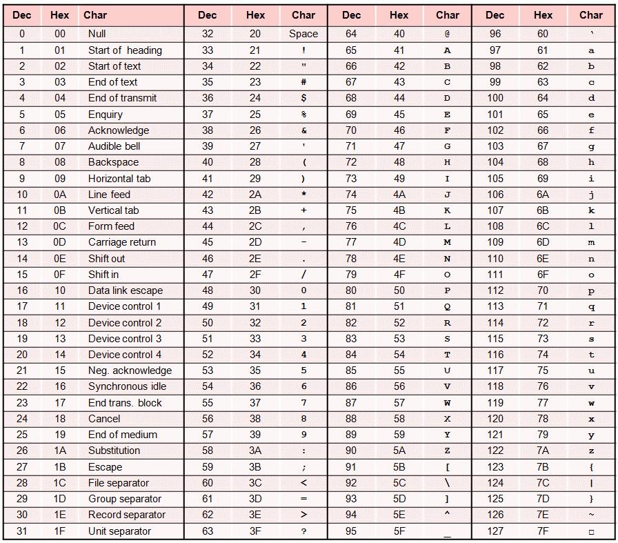
5 3. dc.w (define constant word), dw (define word), fdb (form double bytes) - Define the value of a word or words that will be placed at a given location. - For example: org $800 array dc.w $AC11,$F122,$33,$F44 4. fcc (form constant character) Tells the assembler to store a string of characters (a message) in memory. - The last character must be the same as the first character. - The first and last characters are used as delimiters. - Each character is represented by its ASCII code. $AC $11 $F1 $22 $00 $33 $0F $44 2-3
6 - For example: msg fcc Please enter your name: Org $1000 Alpha fcc def $64 $65 $66 - Assembler will convert to Ascii 5. fill - Example: Org $800 fill $20, 40 ; fill 40 bytes with $20 starting from the memory location $ ds (define storage), rmb (reserve memory byte), ds.b (define storage bytes) - Reserves a number of bytes for later use. - Example: buffer ds 100 ; reserves 100 bytes starting from the location represented by buffer - none of these locations is initialized 2-4
7 2-5
8 7. ds.w (define storage word), rmw (reserve memory word) - Reserve a number of words Dbuf ds.w 20 ;Reserves 20 words (or 40 bytes) starting from the current location counter. 8. equ (equate) - Assigns a value to a label. - Makes programs more readable. - Examples: motor_speed equ 50 The assembler will replace motor_speed with the value 50 in the whole program 2-6
9 Example 1: Array of bytes Example 2: Array of words a1 a1 a2 a2 a1 = $800 a2 = $804 a3 = $807 a3 a3 80D 80E
10 2- Instructions A line of an assembly program Label field - Labels are used to identify memory locations in the programs and data areas. -Optional - Must starts with a letter (A-Z or a-z) and can be followed by letters, digits, or special symbols (_ or.) 2-8
11 Label field - Can start from any column if ended with : - Must start from column 1 if it is not ended with : -Example: Begin: ldaa #10 ; Begin is a valid label Print jsr hexout ; jump to hexout subroutine, Print is a valid label jmp begin ; jump to begin label, do not put : when referring to a label 2-9
12 Comment field -Optional - Explain the function of a single or a group of instructions - For programmer not for assembler or processor. - Ignored by assembler and are not converted to machine code. - Can improve a program readability - very important in assembly - Any line starts with an * or ; is a comment - Separated from the operand for at least one space 2-10
13 Instructions Instructions - Instruct the processor to do a sequence of operations - Converted to machine code - Operands follow the opcode and is separated from the opcode by at least one space - Operands are separated by commas (if there is more than one operand) - Opcode is the operation and separated from the label by at least one space - Assembler instructions or directives are not case sensitive - Must not start at column
14 3- Addressing modes - Addressing modes specify the operand to be operated on. - The addressing mode may specify an immediate value, a register, or a memory location to be used as an operand. The Basic Addressing Modes 1. Inherent 2. Immediate 3. Direct 5. Relative 6. Indexed 7. Indexed-Indirect 4. Extended 2-12
15 1- Inherent Mode - Either do not need operands or all operands are CPU registers. The instruction has only an opcode. - Operands can be detected from the opcode. -Examples:- INX CLRA ABA ;Increment X ; clear A ;A=A+B 2- Immediate Mode - Operands values are included in the instruction. The values are fetched from the machine code in the memory. - An immediate value is preceded by # character 2-13
16 - Example: LDAA #$55 ; A $55 LDX #$1000 ;X $1000 movw #$10, $100 ; m[$100] $00 and m[$101] $10 ;Store the hex values $00 and $10 in ; the memory locations at $100 and $ Direct Mode - The operand is a memory location in the range of $00 to $FF. Examples: LDAA $20 ; A [$20] A = the value at memory location $0020 LDAB $40 ; B [$40] LDX $20 ; X H [$20] X L [$21] 2-14
17 What is the difference between: ldaa $45 ; A = the content of memory location 45 ldaa #$45 ; A = Extended Mode - Same as Direct mode but with using 16-bit memory address. - Used to access any location in the 64 kb memory from 0000 to FFFF LDAA $4000 ; A [$4000] LDX $FE60 ; X [$FE60]:[$FE61] places the first byte in the high-order byte 2-15
18 5- Relative Mode - Used only by branch instructions. - If a branch is taken PC = PC + offset - A short branch instruction: offset is a signed 8-bit can specify a range of -128 ~ A long branch instruction: offset is a signed 16-bit can specify a range of ~ A programmer uses a label to specify the branch target and the assembler will figure out the offset and add it to the machine instruction. -Example: minus bmi minus ;go to minus if N flag in CCR register=
19 6- Indexed Mode - The operand is a memory location. 6.1 Indexed with constant offset - The address of the operand = a base register + a constant offset - The base register can be (X, Y, PC, or SP) Examples ldaa 4,X ; A [4+[X]] Load A with the content of the memory location at address X+4 ldaa 0,X ; A = [0 + [X]] stab -8,X ; Store B at memory location X 8 ldd 100,Y ; A = [100+[Y]], B = [101+[Y]] 2-17
20 6.2 Indexed with an accumulator register offset - The operand address = accumulator + base index register. - The accumulator can be A, B, or D - The base index register can be X, Y, SP, or PC. -Examples: ldaa B,X ;load A with the content of memory location X+B ldy D,X ; Y = memory locations D + X and D + X Indexed with auto pre-/post-increment/decrement of index register - The base register r can be X, Y, or SP. (No PC) - New r = old r + (or -) n - n is the amount of decrement or increment. It is in the ranges -8 thru -1 or 1 thru 8. - Post-decrement/increment: Operand address = old r - Pre-decrement/increment: Operand address = new r 2-18
21 Examples: Assume X has the value $1000 Pre-decrement (n,-r) ldaa 2,-X X = $ = $FFE A = [$FFE] Post-decrement (n,r-) ldaa 2,X- A = [$1000] X = = $FFE Pre-increment (n,+r) ldaa 2,+X X = = $1002 A = [$1002] Post-increment (n,r+) ldaa 2,X+ A = [$1000] X = = $1002 ldaa 1,X+ ; A = [1000] Can be used to read an array. ldaa 1,X+ ; A = [1001] ldaa 1,X+ ; A = [1002] 2-19
22 6.4 Indexed-Indirect - The sum of the base register and offset does not point at the operand address but to the address of memory location where the operand address can be found (address of address) bit Offset Indirect Indexed Addressing - Syntax of the addressing mode is [n,r] - n is 16 bit offset - r is base register X, Y, SP, PC - The operand address = the content of the memory location at n + r - The square brackets distinguish this addressing mode from the 16-bit constant offset indexing. ldaa [10, X] - If X = $1000, then X + 10 = $100A - It reads 16 bits in the locations $100A and next one $100B. Assume this value is $ A = the value stored in location $
23 Example $3A ldaa #$10 A=10 ldaa 10,X A = [X+10] = 20 ldy 10,X Y = [X+10]: [X+11] = 2000 ldaa [10,X] A = [[X+10]] = [2000] = $F ldy [10,X] y = [[X+10]]: [[X+11]] = [2000]: [2001] = F03A
24 6.4.2 Accumulator D Indirect Indexed Addressing - The syntax of this addressing mode is [D,r] - r is base register, X, Y, SP, or PC - The operand address is stored in the memory location D + r The possible addressing modes of each instruction are given in the instruction set file 2-22
25 Summary of important addressing modes Machine code 2-23
26 1. Problem definition: Identify what should be done 2. Identify the inputs and outputs 4- Software Development Process 3. Develop the algorithm (or a flowchart): - The overall plan for solving the problem at hand. - A sequence of operations that transform inputs to output expressed in the following format (pseudo code): Step 1: read a value and store in variable X Step i: N= X Programming: Convert the algorithm into programs. 5. Program Testing: - Testing for anomalies. - Test for the max. and min. values of inputs - Enter values that can test all branches 2-24
27 Outline 2.1 Assembly language program structure 2.2 Data transfer instructions 2.3 Arithmetic instructions 2.4 Branch and loop instructions 2.5 Shift and rotate instructions 2.6 Boolean logic instructions 2.7 Bit test and manipulate instructions 2.8 Stack 2.9 Subroutines

28 Load and Store / Move / Transfer Load: Copies the contents of a memory location (or immediate value) into a register. The memory location does not change but the register changes. Store: Copies the contents of a register into a memory location. The register does not change but the memory location changes. Move: Copies the content of a memory location into other memory location. Transfer: Copies the content of a register into another register. 2-25
29 What to keep in mind to learn how the instructions work - How does the instruction affect registers and/or memory? - How does the instruction affect the flags? - Is it clear where the input numbers are and where the results (destination) should go? 8 or 16 bits? - The instruction is for signed or unsigned numbers? - What kind of addressing modes are available? 1- The LOAD and STORE Instructions - The LOAD instruction copies the content of a memory location or an immediate value to an accumulator or a CPU register. - Memory contents are not changed. - STORE instructions copies a CPU register into a memory location. The register contents are not changed - N and Z flags of the CCR register are automatically updated, the V flag is cleared, and C does not change. 2-26
30 2-27
31 - All except for the relative mode can be used to select the memory location. -Examples: ldaa 0,X ;A = the content of the memory location pointed by X+0 staa $20 ;Store the content of A in the memory location $20 stx $8000 ;Store the content of register X in memory location at $8000 and $8001 ldd #100 ;d = $0100 ldab $1004 ;B = the content of $1004 ldx #$6000 ldd 0,X ldd 2,X ;X = $6000 this can be the beginning address of an array ;read the fist two bytes in the array ;read the second two bytes in the array leax 2,X ; X = the address (not the content) = X + 2 leay d,y ; Y = D + Y 2-28
32 2- Transfer Instructions - Copy the contents of a register into another register. Source register is not changed - TAB copies A to B and TBA copies B to A - TAB and TBA change N and Z, V = 0, and does not change C. -The TFR instruction does not affect any condition code bits. - For example: TFR D,X TFR A,B TFR X,A TFR A,X ; X = D ; B = A ; X[7:0] A, lower 8 bits of X are copied to A ; A is extended to an unsigned 16-bit number and stored in X. X = 00: contents of A - When transferring 8-bit register to 16-bit register, the content of the 8-bit register is extended as unsigned 16-bit number by adding zeroes on left. 2-29
33 The exchange instruction - The EXG instruction swaps the contents of a pair of registers. The contents of the two registers change. - For example: exg A,B ; if A = 1 and B = 2, after executing the instruction A = 2 and B =1 exg D,X exg A,X ; A X[7:0], X $00:[A] exg X,B ; X $00:[B], B X[7:0] Unsigned Exchange 8- bits register with 16 bits one - Signed Exchange: SEX A,X - A = X[0:7] the lowest 8 bits in X - X = $00:[A] if the number in A is positive - X = $FF:[A] if the number in A is negative To extend 8-bit positive number to 16 bits, add zeroes on the left - To extend 8-bit negative number to 16 bits, add ones on the left
34 2-31
35 3- Move Instructions - Copy a byte or a word from a memory location (or immediate value) to other memory location - Do not change all the flags. -Example: movb $1000,$2000 ; Copies the byte at memory location $1000 to the memory location at $2000 movw 0,X,0,Y ; Copy 16 bit word pointed by X+0 to the location pointed by Y+0 movb #3A,$0F ; the memory location 0F = 3A 2-32
36 Outline 2.1 Assembly language program structure 2.2 Data transfer instructions 2.3 Arithmetic instructions 2.4 Branch and loop instructions 2.5 Shift and rotate instructions 2.6 Boolean logic instructions 2.7 Bit test and manipulate instructions 2.8 Stack 2.9 Subroutines
37 1- Add and Subtract Instructions - The destinations are always a CPU register. - Update N, Z, N, and C flags. -Examples: adda $1000 ; A [A] + [$1000] adca $1000 ; A [A] + [$1000] + C suba $1002 ; A [A] - [$1002] sbca $1000 ; A [A] - [$1000] C (A - B) is done by adding A to the two s complement of B 2-33
38 <opr> field is specified using one of the addressing modes. All addressing modes except inherent and relative can be used 2-34
39 - Zero flag (Z): set when the result is zero - Negative flag (N): set whenever the result is negative, i.e., most significant bit of the result is 1. - Carry/borrow flag (C): set when addition/subtraction generates a carry/borrow. - Overflow flag (V): Set when: the addition of two positive numbers results in a negative number or the addition of two negative numbers results in a positive number. 2-35
40 Overflow Problem: fixed width registers have limited range Overflow occurs when two numbers are added or subtracted and the correct result is outside the range that can a register hold the given result is not correct Addition: C = 1 there is an overflow if the numbers are unsigned. V = 1 there is an overflow if the numbers are signed. Overflow cannot occur when adding numbers of opposite sign why? Subtraction: A - B There is no unsigned overflow but there is signed overflow C = 1, when there is a borrow or B > A, C is called borrow flag V =1, when (-ve) - (+ve) = (+ve) this is equivalent to ( ve) + (-ve) = (+ve) (+ve) - (-ve) = (-ve) this is equivalent to (+ve) + (+ve) = (-ve) 2-36
41 C = 1, V = 0, Z = 1, N =0 Signed numbers: = 0, no overflow and the result is correct Unsigned numbers: = 0, incorrect, the correct result is 256, overflow because the max. unsigned number for 8 bit number is By using more bits (9 bits or more) instead of 8 bits, the result is correct, no overflow C = 0, V = 0, Z = 0, N = 1 Signed numbers: = -1, no overflow and the result is correct Unsigned numbers: = 255, no overflow and the result is correct 2-37
42 C = 0, V = 1, Z = 0, N = 1 Unsigned numbers: = 128, no overflow and the result is correct Signed numbers: = -128, there is overflow, the result is incorrect, the max. positive number in 8 bits is 127 that is less than the correct answer 128. If we use 9 bit addition, the result will be correct because 128 can be represented in 9 bits C = 0, V = 0, Z = 0, N = C = 1, V = 1, Z = 0, N = 0 Unsigned numbers: = 54 should be 310, overflow, 255 is the max. number for 8 bit number Signed numbers: (-118) = 54, should be -202, overflow, the max. negative number in 8 bits is -128 that is less than the correct answer 2-38
43 If we use 9 bit addition, the result will be correct. Unsigned numbers: C = 0 Signed numbers: V = 0 Subtraction: A B = A + the two s complement of B V = 0, C = 0, N = 0, Z =0 C is called borrow flag and it is set when we need to borrow from the most significant byte Unsigned numbers: = 30 correct Signed numbers: = 30 correct V = 0 because (+ve) (+ve) no overflow 2-39
44 V = 1, C = 1, N = 1, Z = Unsigned numbers: - There is borrow, = What happened is (92+256) -138 = 210, where 256 is the borrow - If we do muti-byte subtraction, the result (210) is right and we should subtract one from the next byte. - If you want to get the absolute difference 46, subtract the small number from the bigger one or = 46 Signed numbers:- 92 (-118) = -46 should be 210, V = 1 means the numbers should be represented in more bits V =
45 Write a code to subtract the contents of the memory location at $1005 from the sum of the memory locations at $1000 and $1002, and store the difference at $1100. ldaa $1000 ; A = [$1000] adda $1002 ; A = A + [$1002] suba $1005 ; A = A [$1005] staa $1100 ; [$1100] = A Write a code to add the byte pointed by register X and the following byte and store the sum at the memory location pointed by register Y. ldaa 0,X ; store the byte pointed by X in A adda 1,X ; add the following byte to A staa 0,Y ; store the sum at location pointed by Y Write a code to swap the 2 bytes at $100 and $200. copy $100 2 $200 copy 1 A 3 copy 2-41
46 ldaa $100 ; A = [$100] movb $200,$100 ; store [$200] in memory location $100 staa $200 ; store A in the memory location $200 Write a code to add 3 to the memory locations at $10 and $15. A memory location cannot be the destination in ADD instructions. We need to copy the memory content into register A or B, add 3 to it, and then return the sum back to the same memory location. ldaa $10 ; copy the contents of memory location $10 to A adda #3 ; add 3 to A staa $10 ; store the sum to memory location at $10 ldaa $15 ; copy the contents of memory location $15 to A adda #3 ; add 3 to A staa $15 ; store the sum to memory location at $
47 Multi-precision arithmetic - HCS12 can add/sub at most 16-bit numbers using one instruction - To add/sub numbers that are larger than 16 bits, we need to consider the carry or borrow resulted from 16-bit operation. How to add (or subtract) two 32-bit numbers Most significant byte C C Least significant word 8-bit number 8-bit number 16-bit number Add with carry (or sub with borrow) 8-bit number Add with carry (or Sub with borrow) 8-bit number Add (or sub) 16-bit number - Carry flag is set to 1 when the addition operation produces a carry. This carry should be added to the next addition operation - Carry flag is set to 1 when the subtraction operation produces a borrow. This borrow should be subtracted from the next subtraction operation 2-43
48 Write a program to add two 4-byte numbers that are stored at $1000- $1003 and $1004-$1007, and store the sum at $1010-$1013. The addition starts from the lease significant byte and proceeds toward the most significant number. carry carry [$1000] [$1001] [$1002] [$1003] Add with carry Add with carry add [$1004] [$1005] [$1006] [$1007] [$1010] [$1011] [$1012] [$1013] Notice there is no instruction for addition with carry for 16 bits. 2-44
49 ; Add and save the least significant two bytes ldd $1002 ; D [$1002]:[$1003] addd $1006 ; D [D] + [$1006]:[$1007] C std $1012 ; [$1012]:[$1013] [D] ; Add and save the second most significant bytes ldaa $1001 ; A [$1001] adca $1005 ; A [A] + [$1005] + C staa $1011 ; $1011 [A] ; Add and save the most significant bytes ldaa $1000 ; A [$1000] std and ldaa do not change the carry so C is the carry resulted from addd $1006 adca $1004 ; A [A] + [$1004] +C staa $1010 ; $1010 [A] For subtraction: The same code can be used but use subd instead of addd sbca instead of adca 2-45
50 2- Decrementing and incrementing instructions These instructions are faster than using Add/sub instructions. ldaa $10 adda #1 staa $10 = inc $10 <opr> Updated flags N Z V None Z <opr> N Z V None Z <opr> can be direct, extended, or indexed addressing modes. 2-46
51 3- Clear, Complement and Negate instructions Updated flags C = 0 I = 0 NZVC = 0100 V = 0 NZVC = YY01 NZVC = YYYY - Clear command stores 0 in registers/memory locations. Used for initialization. - Complement command computes the one s complement. - Negate command computes the two s complement. 2-47
52 4- Multiplication and Division instructions The upper 16 bits in Y and the lower ones in D NZVC = YYNY NZVC = NNNY NZVC = YYYY NZVC = NYYY NZVC = NY0Y NZVC = YYYY 2-48
53 Write an instruction sequence to multiply the 16-bit numbers stored at $1000-$1001 and $1002-$1003 and store the product at $1100-$1103. ldd $1000 ;load first word ldy $1002 ;load second word emul ;[D] x [Y] Y:D use emuls if the numbers are signed sty $1100 ; store most significant 16 bits in 1100 and 1101 std $1102 ; store least significant 16 bits in 1102 and 1103 Write an instruction sequence to divide the signed 16-bit number stored at $1020-$1021 by the signed 16-bit number stored at $1005-$1006 and store the quotient and remainder at $1100 and $1102, respectively. ldd $1005 ldx $1020 idivs ; D/X X = qutient, D = remainder, use idiv if numbers are unsigned stx $1100 ; store the quotient (16 bits) at $1100 and $1101 std $1102 ; store the remainder (16 bits) ;To compute the squared value of A tab ;B = A mul ;A:B = A x B 2-49
54 Converting binary number to decimal Input: Binary number (= in decimal) Binary to decimal conversion Binary to decimal conversion Output: equivalent decimal number Can be sent to the LCD 2-50
55 - Using repeated division by The largest 16-bit number is 65,535 which has five decimal digits. - The first division by 10 generates the least significant digit (in the remainder) = = = = Quotient Remainder Least significant = Most significant 2-51
56 Write a program to convert the 16-bit number stored at register D to decimal store the result at memory locations $1010 to $1014. ldy #$1010 ;Y points at the first address of the decimal result ldx #10 ;X =10 idiv ;D/X Quotient X, Remainder D stab 4,Y ;save the least significant digit (5) xgdx ; D = the quotient required for the next division ldx #10 ; X =10 idiv ; D/10 Quotient X, Remainder D Assume: D = stab 3,Y ;save the second number (4) xgdx ; D = the quotient required for the next division Y $1010 $1011 $ $ Y+4 $
57 ldx #10 ; X =10 idiv ; D/10 Quotient X, Remainder D stab 2,Y ;save the third number (3) xgdx ; D = the quotient ldx #10 ; X =10 idiv ; D/10 Quotient X, Remainder D stab 1,Y ;save the second number (2) xgdx ; D = the quotient addb #$30 stab 0,Y ; save the most significant digit (1) Y Y+4 $1010 $1011 $1012 $1013 $
58 Converting decimal number to binary Input: decimal number Most significant number N1 = 1 N2 = 2 N3 = 3 N4 = 4 N5 = 5 Can come from the keypad Decimal to binary conversion Decimal to binary conversion Output: equivalent binary number (= in decimal) 2-54
59 Binary = ((((N1x 10) + N2) x 10 + N3) x 10 + N4) x 10 + N = N1 x N2 x N3 x N4 x 10 + N5 Write a program to convert a 5-digit number stored at memory locations $1010 to $1014 into its 16-bit equivalent binary number. Store the result in memory locations $2000 and $2001. ; processing N1 ldaa $1010 ; A = N1 (the most significant digit) ldab #10 ; B = 10 mul ; operation 1 D = N1 x 10 std $2000 ; store the result in $2000 and $2001 $1010 $1011 $1012 $1013 ; processing N2 $1014 ldab $1011 ; B = N2 clra ; A = 0 so D = A:B = 00: N2 addd $2000 ;operation 2 d = [$2000]+D = (N1 x 10) + N
60 ; process N3 ldy #10 ; Y = 10 emul ; Y:D = D x Y operation 3 std $2000 ;d = ((N1 x 10) + N2) x 10 ldab $1012 ; B = N3 clra ; A = 0 so D = A:B = 00: N3 addd $2000 ;operation 4 d = ((N1 x 10) + N2) x 10 + N3 ; process N4 ldy #10 ; Y = 10 emul ; Y:D = D x Y operation 5 std $2000 ;d = (((N1 x 10) + N2) x 10 + N3) x 10 ldab $1013 ; B = N3 clra ; A = 0 so D = A:B = 00: N4 addd $2000 ;operation 6 d = ((((N1 x 10) + N2) x 10 + N3) x 10) + N4 2-56
61 ; process N5 ldy #10 ; Y = 10 emul ; Y:D = D x Y operation 7 std $2000 ;d = d = (((((N1 x 10) + N2) x 10 + N3) x 10) + N4)x 10 ldab $1014 ; B = N5 clra ; A = 0 so D = A:B = 00: N5 addd $2000 ;operation 8 d = ((((((N1 x 10) + N2) x 10 + N3) x 10) + N4)x 10 ) + N5 2-57
62 Outline 2.1 Assembly language program structure 2.2 Data transfer instructions 2.3 Arithmetic instructions 2.4 Branch and loop instructions 2.5 Shift and rotate instructions 2.6 Boolean logic instructions 2.7 Bit test and manipulate instructions 2.8 Stack 2.9 Subroutines
63 1. Branch instructions Conditional or unconditional Short or long Signed or unsigned Unconditional branches - Branches are always taken Conditional branches - A branch is taken if a condition is satisfied. - A condition is satisfied if certain flags are set. - Usually we use a comparison or arithmetic command to set up the flags before the branch instruction. CBA ; compare A to B - used to set the flags LBHI next ; branch to next if A > B LBHI tests the flags 2-58
64 1. Branch instructions Conditional or unconditional Short or long Signed or unsigned Short branches - The range of the branch is -128 and +127 bytes. Long branches - Can branch to anywhere in the memory Next1: Next2: BRA Next1 BRA Next <= 128 <= 127 For peace of mind, always use long branches 2-59
65 1. Branch instructions Conditional or unconditional Unsigned branches Short or long Signed or unsigned - The numbers of the condition are unsigned - Use instructions: branch if higher (LBHI), branch if higher or same (LBHS), branch if lower (LBLO), and branch if lower and same (LBLS). Signed branches - The numbers of the condition are Signed - Use instructions: branch if greater (LBGT), branch if greater or equal (LBGE), branch if less (LBLE), and branch if less and equal (LBLE). ; A = B = CPA ; compare A and B. Used to set the flags LBHI next ; unsigned the branch is taken because A = 225 > B =1 LBGT next ; Signed the branch is not taken because A = -1 is not greater than B =1 2-60
66 Unconditional branch branch is taken when a specific flag is 0 or
67 2. Compare and Test instructions - Flags should be set up before using conditional branch instructions. - The compare and test instructions perform subtraction, set the flags based on the result, and does not store the result. ONLY change flags. The memory and register does not change <opr> can be an immediate value or a memory location 2-62
68 3. Loop instructions - Repeat a sequence of instructions several times. - Either decrement or increment a count to determine if the loop should continue. - The range of the branch is from -128 to Note: rel is the relative branch offset and usually a label 2-63
69 4. Bit condition branch instructions - Make branch decision based on the value of few bits in a memory location. brclr <opr>,msk,rel ;Branch is taken when the tested bits are zeroes brset <opr>,msk,rel ;Branch is taken when the tested bits are ones <opr>: The memory location to be checked. msk: 8 bits that specifies the bits of to be checked. The bits to be checked correspond to those that are 1s in msk. rel : if a branch is taken, it branches to the label rel loop: brset $66,$E0,loop The branch is taken if the last three bits at memory location $66 are all ones. Notice: $E0 = % brclr $66,$80,here here: The branch is taken if the most significant bit at the memory location $66 is zero. Notice: $80 = %
70 How brclr and brset work? 1 and Bi = Bi put 1 at the bits you test 0 and Bi = 0 put 0 at the bits you do not test I wanna test These bits AND B7 B6 B5 B4 B3 B2 B1 B mask B1 B0 <opr> This number is zero if B0 and B1 are zeros, otherwise it is not zero 2-65
71 1. Endless loop Looping mechanisms do a sequence of instructions (S) forever. Loop: LBRA Loop Repeat these instructions forever 2. For loops For (i = n1, i <= n2, i++) {a sequence of instructions (S) } - i is loop counter that can be incremented in each iteration. - Sequence S is repeated n2-n1+1 times Steps: 1- Initialize loop counter 2- Compare the loop counter with n2. If it is not equal, do the loop otherwise exit 3- increment the loop and go to step
72 Implementation of for (i = 1, i <= 20, i++) {S} i ds.b 1 ; i is the loop counter movb #1,i ;initialize i to 1 Loop: ldaa i ; A = [i] cmpa #2 ; check index i LBHI Next ; if i > n2, exit the loop 1 2? ; performs S ; inc i ;increment loop index lbra Loop ;go back to the loop body Next: Since i is a byte, the max. number of iterations is 256. For more iterations, use two loops (outer and inner loops) 2-67
73 For loop using dbeq up to 65,535 iterations ldx #6000 ; number of iterations Loopf: dbeq x,next. ; performs S.. lbra Loopf next: May be a good idea to use a memory location as a loop counter because you may need to use X to perform the sequence S 2-68
74 While Loop While (condition) { Sequence S; } - S is executed as long as the condition is true - Unlike for loop, the number of iterations may not be known beforehand While (A 0) {Sequence S;} Wloop: cmpa #0 lbeq Next. ; perform S.. lbra Wloop Next: A is updated in the instruction sequence S 2-69
75 I ds.b 1 ldaa I cmpa #1 lbne end_if. ; perform S.. ; end_if: If (I == 1) {Sequence S;} If I does not equal 1, skip the Sequence S If ( I == 1) {Sequence S1;} else {Sequence S2;} I ds.b 1 ldaa I ; A = I cmpa #1 lbne else ; perform S1 ; lbra end_if else:. ; perform S2.. ; end_if: 2-70
76 If ( A == 1 and B > 8) {Sequence S;} cmpa #1 lbne end_if ; the first condition is satisfied test the second one cmpb #8 lbls end_if. ; perform S.. ; end_if: Sequence S is executed only when the two conditions are satisfied, i.e., if one condition is not satisfied, do not execute S cmpa #1 lbeq perform_s ; the first condition is not satisfied. Try the second one cmpb 8 lbhi perform_s ;the two conditions are not satisfied, go to end_if lbra end_if perform_s:. ; perform S.. ; end_if: If ( A == 1 or B > 8) {Sequence S;} Sequence S should be executed when at least one condition is satisfied, i.e., S is not executed when the two conditions are not satisfied 2-71
77 IF ELSE IF If (condition 1) {Sequence S1;} Else If (condition 2) {Sequence S2;} Else If (condition 3) {Sequence S3;} Else {Sequence Se;} If (A == 1) {Sequence S1;} Else If (A == 2) {Sequence S2;} Else If (A == 3) {Sequence S3;} Else {Sequence Se;} if1: cmpa #1 lbne if2 ; perform S1 lbra end_if if2: cmpa #2 lbne if3 ; perform S2 lbra end_if if3: cmpa #3 lbne else ; perform S3 lbra end_if else:. ; perform Se end_if: 2-72
78 Switch Case Switch (variable) Case 1: Sequence S1; Break; Case 2: Sequence S2; Break; Case 3: Sequence S3; Break; Else: Sequence Se; I rmb 1 ldaa I ; A = I cmpa #1 lbeq Case1 cmpa #2 lbeq Case2 cmpa #3 lbeq Case3 lbra else Case1: ; perform S1 lbra end_case Case2: ; perform S2 lbra end_case Case3: ; perform S3 lbra end_case else:. ; perform Se end_case: 2-73
79 Write a code to calculate the absolute value of the memory location $1000. Store the result in $1000 ldaa $1000 cmpa #00 lbge done ; do nothing if [$1000] >=0 ; the number is negative nega staa $1000 done: 2-74
80 Write a program to find the maximum element in an array of 20 elements and each element is byte. The array starts from location $2000 max_value = Array[0] Array[i] i = 1 i = 2 i = 3 i = max_value = Array [1] 2- Scan the array from Array[2] to Array [20] 3- In each iteration: if Array[i] > max_value then max_value = Array[i] 4- After scanning all the array elements, max_value = the max. element 2-75
81 org $1000 ; starting address of data max_val ds.b 1 ; max. value is hold here org $1500 ; starting address of program ldaa $2000 staa max_val ; A = the first element ; max_val = the first element ldx #$2001 ; X = the address of the second element ldab #19 ;b is the loop count = 19 Loop: ldaa max_val ;A = max_val cmpa 0,x ;compare A and the element at 0,X lbge chk_end ; do not change max_value if it is greater ; an element greater than max_val is found movb 0,x,max_val ;update the array s max value chk_end: inx ; move to the next array element dbne b,loop ; loop for 19 times Can you modify this code to find the minimum value? 2-76
82 Write a program to compute the number of elements that are divisible by 4 in an array of 5 elements. Each element is a byte. A number is divisible by 4 when the least significant two bits equal 0s. org $1000 total ds.b 1 ; to store the number of elements divisible by 4 array dc.b 1,2,3,4,5 org $1500 clr total ; initialize total to 0 ldx #array ; X = the starting address of the array, use X as the array pointer ldab #5 ; use b as the loop count loop: brclr 0,X,$03,yes ; check bits number 0 and 1 bra chkend yes: inc total chkend: inx dbneb,loop ;point at the next element in the array 2-77
83 Outline 2.1 Assembly language program structure 2.2 Data transfer instructions 2.3 Arithmetic instructions 2.4 Branch and loop instructions 2.5 Shift and rotate instructions 2.6 Boolean logic instructions 2.7 Bit test and manipulate instructions 2.8 Stack 2.9 Subroutines
84 1. Logical shift instructions 1.1 Logical shift left C b b0 0 b7 b b1 0 One bit shift Shifting one byte data lsl <opr> lsla lslb ; Memory location opr is shifted left by one bit ; Accumulator A is shifted left by one bit ; Accumulator B is shifted left by one bit After shifting A eight times, what s the value of A? lsld ;16-bit logical shift left instruction for D Shifting one byte data C b b0 b b0 0 A B 2-78
85 1.2 Logical shift right 0 b b0 0 b b1 C b0 lsr <opr> lsra lsrb ; Memory location opr is shifted right one place ; Accumulator A is shifted right one place ; Accumulator B is shifted right one place 0 b b0 A b b0 B C lsrd ;16-bit logical shift right instruction for D 2-79
86 2. Arithmetic shift instructions 2.1 Arithmetic shift left - Shift left is equivalent to multiply by 2. - For example, % = 4 After one shift left: % = 8 - Faster than multiply instructions C b b0 0 asl <opr> asla aslb ; Memory location opr is shifted left one place ; Accumulator A is shifted left one place ; Accumulator B is shifted left one place C b b0 b b0 0 A B asld ;16-bit arithmetic shift left instruction logical shift left D 2-80
87 2.2 Arithmetic shift right - Arithmetic shift right is equivalent to divide by 2. - For example, % = 8 After one shift right : % = 8 - Faster than divide instructions b b0 C asr <opr> asra asrb ; Memory location opr is shifted right one place ; Accumulator A is shifted right one place ; Accumulator B is shifted right one place Asr shifts by the last bit instead of 0 to keep the number s sign. No 16 bit arithmetic shift right 2-81
88 3. Rotate instructions 3.1 Rotate left C b b0 rol <opr> rola rolb ; Memory location opr is rotated left one place ; Accumulator A is rotated left one place ; Accumulator B is rotated left one place No 16 bit rotate left instruction After rotating A 9 times, what s the value of A? b b0 C ror <opr> rora rorb ; Memory location opr is rotated right one place ; Accumulator A is rotated right one place ; Accumulator B is rotated right one place No 16 bit rotate right instruction 2-82
89 <opr> <opr> <opr> <opr> <opr> <opr> 2-83
90 Example: Suppose that [A] = $95 and C = 1. Compute the new values of A and C after the execution of the instruction asla. accumulator A Original value New value C flag [A] = C = 1 [A] = C = Figure 2.11b Execution result of the ASLA instruction Figure 2.11a Operation of the ASLA instruction Example: Suppose that m[$800] = $ED and C = 0. Compute the new values of m[$800] and C after the execution of asr $1000. memory location $ C flag Original value [$1000] = C = 0 New value [$1000] = C = 1 Figure 2.12a Operation of the ASR $1000 instruction Figure 2.12b Result of the asr $1000 instruction 2-84
91 Example: Suppose that m[$800] = $E7 and C = 1. Compute the new contents of m[$800] and C after the execution of lsr $800. Example: Suppose that [B] = $BD and C = 1. Compute the new values of B and the C flag after the execution of rolb. 2-85
92 Example: Suppose that [A] = $BE and C = 1. Compute the new values of A and C after the execution of the instruction rora. 2-86
93 Example: Write a program to count the number of 0s in the 16-bit D register and store the result in memory location $1005. After iteration 1: After iteration 2: C C 1 C 0 After iteration 15: After iteration 16: A B C 1 C 1 - The 16-bit number is shifted to the right - If the bit shifted out is a 0 then increment the 0s count by 1. - Loop for 16 iterations 2-87
94 org $1005 zero_cnt dc.b0 ; variable to store the number of zeroes, the initial value = 0 lp_cnt dc.b 16 ; variable for the loop counter. the initial value = 16 org $1500 Loop: lsrd ; shift the lsb of D to the C flag lbcs chkend ; branch if the C flag (= LSB bits) is 1 inc zero_cnt ; increment 0s count if the lsb is a 0 Chkend: dec lp_cnt ; check to see if D is already 0 lbne loop Can you modify the program to count the number of ones? An application: In voting system, each bit can reflect a switch condition (connected or disconnected). We use this program to count the number of approvals (ones) and the number of disapprovals (zeros) 2-88
95 Shift right a multi-byte number HCS12 instructions can shift 8 or 16 bit numbers 0 Byte1 msb Byte2. lsb C Byte1 0 C msb lsr Byte2 C ror. C ror Loc+k-1 Rotate right can be used a shift right with carry Use lsl and rol for shifting left lsb ror C 2-89
96 Example Write a program to shift the 32-bit number stored at $820- $823 to the right four places. ldab #4 ldx #$820 Again: lsr 0,X ror 1,X ror 2,X ror 3,X ; set up the loop count = the number of shifts ; use X as the pointer to the left most byte One bit shift operation for 32 bit number dbne b,again ; decrement b and loops if it is not 0 Can you change the code to shift the 32-bit number to the left? 2-90
97 Outline 2.1 Assembly language program structure 2.2 Data transfer instructions 2.3 Arithmetic instructions 2.4 Branch and loop instructions 2.5 Shift and rotate instructions 2.6 Boolean logic instructions 2.7 Bit test and manipulate instructions 2.8 Stack 2.9 Subroutines

98 - Logic instructions perform a logic operation between an 8-bit accumulator or the CCR and a memory or immediate value. <opr> can be specified using all except the relative addressing modes 2-91
99 AND is used to reset one or more bits Ex. Clear the first 4 bits in register B I wanna reset these bits AND B7 B6 B5 B4 B3 B2 B1 B mask B Thanks to: Bi AND 0 = 0 Bi AND 1 = Bi B7 B6 B5 B OR is used to set one or few bits Ex. Set the first 4 bits in register B I wanna set these bits OR B7 B6 B5 B4 B3 B2 B1 B mask B Thanks to: Bi OR 0 = Bi Bi OR 1 = 1 B7 B6 B5 B


100 XOR is used to flip (change 0 to 1 and 1 to 0) one or more bits Ex. Flip the first 4 bits in register B I wanna set these bits XOR B7 B6 B5 B4 B3 B2 B1 B mask B B7 Thanks to: Bi XOR 0 = Bi Bi XOR 1 = Bi Bi = the inversion of Bi B6 B5 B4 B3 B2 B1 B0 Exclusive or AND OR 2-93
101 ldaa $56 anda #$0F staa $56 Clear the upper 4 pins of the I/O port located at $56 ldaa $56 oraa #$01 staa $56 Set the bit 0 of the I/O port at $56 ldaa $56 eora #$0F staa $56 Toggle (or flip) the lower 4 bits of the I/O port at $56 ldaa $10 oraa #% staa $10 Force bits 3,4 of [$10] to be 1 s ldaa $10 anda #% staa $10 Force bits 3,4 of [$10] to be 0 s Test if both bits 5 and 6 of A are zeroes anda #% lbeq bothzeros ; branch if Z flag =
102 Outline 2.1 Assembly language program structure 2.2 Data transfer instructions 2.3 Arithmetic instructions 2.4 Branch and loop instructions 2.5 Shift and rotate instructions 2.6 Boolean logic instructions 2.7 Bit test and manipulate instructions 2.8 Stack 2.9 Subroutines

103 <opr>: memory location. msk8: 8-bit mask value. Used to test or change the value of individual bits. bita and bitb are used to test bits without changing the value of the operand. They do AND operation and update flags but do not store the result. Used to set the flags before a branch instruction. ldaa $10 bita #% bne eitherones Bita does [$10] AND % This masks off (zeroes) all bits except bits 5 and 6. Branch is taken if either bit 5 or 6 is one. 2-95
104 bclr 0,X,$81 ; clear the most significant and least significant bits of the memory location pointed by register X ($81=% ) bclr $812,$81 ; Clear bits 0 and 7 in location $812. It does not change the other bits. bset 0,y,$33 ;Sets bits five, four, one, and zero of memory location pointed to by register Y bset $810,$4 ; Set bit 2 in memory location $810. It does not change the other bits. What is the difference between bclr and brclr (slide 2-64 ) 2-96
Chapter 2: HCS12 Assembly Programming. EE383: Introduction to Embedded Systems University of Kentucky. Samir Rawashdeh
 Chapter 2: HCS12 Assembly Programming EE383: Introduction to Embedded Systems University of Kentucky Samir Rawashdeh With slides based on material by H. Huang Delmar Cengage Learning 1 Three Sections of
ECET Chapter 2, Part 3 of 3
 ECET 310-001 Chapter 2, Part 3 of 3 W. Barnes, 9/2006, rev d. 10/07 Ref. Huang, Han-Way, The HCS12/9S12: An Introduction to Software and Hardware Interfacing, Thomson/Delmar. In This Set of Slides: 1.
Lecture 7 Assembly Programming: Shift & Logical
 CPE 390: Microprocessor Systems Fall 2017 Lecture 7 Assembly Programming: Shift & Logical Bryan Ackland Department of Electrical and Computer Engineering Stevens Institute of Technology Hoboken, NJ 07030
Table 1: Mnemonics Operations Dictionary. Add Accumulators Add B to Y. Add with carry to B. Add Memory to B. Add 16-bit to D And B with Memory
 Table 1: Mnemonics s Dictionary ABA ABX ABY ADCA ADCB ADDA ADDB ADDD ANDA ANDB ASL ASLA ASLB ASLD ASR ASRA ASRB BCC BCLR BCS BEQ BGE BGT BHI BHS BITA BITB BLE BLO BLS BLT Add Accumulators Add B to X Add
Programming the Motorola MC68HC11 Microcontroller
 Programming the Motorola MC68HC11 Microcontroller COMMON PROGRAM INSTRUCTIONS WITH EXAMPLES aba Add register B to register A Similar commands are abx aby aba add the value in register B to the value in
2) [ 2 marks] Both of the following statements cause the value $0300 to be stored in location $1000, but at different times. Explain the difference.
![2) [ 2 marks] Both of the following statements cause the value $0300 to be stored in location $1000, but at different times. Explain the difference.](/thumbs/74/70477363.jpg "2) [ 2 marks] Both of the following statements cause the value $0300 to be stored in location $1000, but at different times. Explain the difference.") 1) [ 9 marks] Write a sequence of directives for an HCS12 assembly language program that performs all of these tasks, in this order: a) Define an array called Measurements starting from memory location
1) [ 9 marks] Write a sequence of directives for an HCS12 assembly language program that performs all of these tasks, in this order: a) Define an array called Measurements starting from memory location
ECET Chapter 2, Part 2 of 3
 ECET 310-001 Chapter 2, Part 2 of 3 W. Barnes, 9/2006, rev d. 10/07 Ref. Huang, Han-Way, The HCS12/9S12: An Introduction to Software and Hardware Interfacing, Thomson/Delmar. In This Set of Slides: 1.
ELECTRICAL AND COMPUTER ENGINEERING DEPARTMENT, OAKLAND UNIVERSITY ECE-470/570: Microprocessor-Based System Design Fall 2014.
 c 2 =1 c 1 =1 c 0 =0 c 2 =1 c 1 =1 c 0 =0 c 4 =0 c 3 =0 c 2 =0 c 1 =0 c 0 =0 c 2 =0 c 1 =0 c 0 =1 c 2 =0 c 1 =0 c 0 =0 ELECTRICAL AND COMPUTER ENGINEERING DEPARTMENT, OAKLAND UNIVERSITY Notes - Unit 4
ECE331 Handout 3- ASM Instructions, Address Modes and Directives
 ECE331 Handout 3- ASM Instructions, Address Modes and Directives ASM Instructions Functional Instruction Groups Data Transfer/Manipulation Arithmetic Logic & Bit Operations Data Test Branch Function Call
EE4390 Microprocessors
 EE4390 Microprocessors Lesson 6,7 Instruction Set, Branch Instructions, Assembler Directives Revised: Aug 1, 2003 1 68HC12 Instruction Set An instruction set is defined as a set of instructions that a
Addressing Mode Description Addressing Mode Source Format Abbrev. Description
 Addressing Mode Description Addressing Mode Source Format Abbrev. Description Inherent INST (no operands) INH Operands (if any) are in CPU registers Immediate INST #opr8i or INST #opr16i IMM Operand is
MC9S12 Assembler Directives A Summary of MC9S12 Instructions Disassembly of MC9S12 op codes. Summary of HCS12 addressing modes ADDRESSING MODES
 MC9S12 Assembler Directives A Summary of MC9S12 Instructions Disassembly of MC9S12 op codes o Review of Addressing Modes o Which branch instruction to use (signed vs unsigned) o Using X and Y registers
The Motorola 68HC11 Instruc5on Set
 The Motorola 68HC11 Instruc5on Set Some Defini5ons A, B * accumulators A and B D * double accumulator (A + B) IX, IY * index registers X and Y SP * stack pointer M * some memory loca5on opr * an operand
Lecture 5 Assembly Programming: Arithmetic
 CPE 390: Microprocessor Systems Spring 2018 Lecture 5 Assembly Programming: Arithmetic Bryan Ackland Department of Electrical and Computer Engineering Stevens Institute of Technology Hoboken, NJ 07030
Lecture 6 Assembly Programming: Branch & Iteration
 CPE 390: Microprocessor Systems Spring 2018 Lecture 6 Assembly Programming: Branch & Iteration Bryan Ackland Department of Electrical and Computer Engineering Stevens Institute of Technology Hoboken, NJ
Disassembly of MC9S12 op codes Decimal, Hexadecimal and Binary Numbers
 Disassembly of MC9S12 op codes Decimal, Hexadecimal and Binary Numbers o How to disassemble an MC9S12 instruction sequence o Binary numbers are a code and represent what the programmer intends for the
Disassembly of MC9S12 op codes Decimal, Hexadecimal and Binary Numbers
 Disassembly of MC9S12 op codes Decimal, Hexadecimal and Binary Numbers o How to disassemble an MC9S12 instruction sequence o Binary numbers are a code and represent what the programmer intends for the
EE 3170 Microcontroller Applications
 Q. 3.9 of HW3 EE 37 Microcontroller Applications (a) (c) (b) (d) Midterm Review: Miller Chapter -3 -The Stuff That Might Be On the Exam D67 (e) (g) (h) CEC23 (i) (f) (j) (k) (l) (m) EE37/CC/Lecture-Review
2. Arithmetic Instructions addition, subtraction, multiplication, divison (HCS12 Core Users Guide, Sections 4.3.4, and ).
.") AS12 Assembler Directives A Summary of 9S12 instructions Disassembly of 9S12 op codes Huang Section 1.8, Chapter 2 MC9S12 V1.5 Core User Guide Version 1.2, Section 12 o A labels is a name assigned the
AS12 Assembler Directives A Summary of 9S12 instructions Disassembly of 9S12 op codes Huang Section 1.8, Chapter 2 MC9S12 V1.5 Core User Guide Version 1.2, Section 12 o A labels is a name assigned the
Disassembly of an HC12 Program It is sometimes useful to be able to convert HC12 op codes into mnemonics. For example, consider the hex code:
 Disassembly of an HC12 Program It is sometimes useful to be able to convert HC12 op codes into mnemonics. For example, consider the hex code: ADDR DATA ---- ------------------------------------------------------
ECE 3120 Computer Systems Arithmetic Programming
 ECE 3120 Computer Systems Arithmetic Programming Manjeera Jeedigunta http://blogs.cae.tntech.edu/msjeedigun21 Email: msjeedigun21@tntech.edu Tel: 931-372-6181, Prescott Hall 120 Today: Multiplication and
N bit is set if result of operation in negative (MSB = 1) Z bit is set if result of operation is zero (All bits = 0)
 Z bit is set if result of operation is zero (All bits = 0)") Addition and Subtraction of Hexadecimal Numbers. Setting the C (Carry), V (Overflow), N (Negative) and Z (Zero) bits How the C, V, N and Z bits of the CCR are changed Condition Code Register Bits N, Z,
Addition and Subtraction of Hexadecimal Numbers. Setting the C (Carry), V (Overflow), N (Negative) and Z (Zero) bits How the C, V, N and Z bits of the CCR are changed Condition Code Register Bits N, Z,
Department of Computer Science and Engineering
 Department of Computer Science and Engineering Instruction Set Overview This is a complete overview of the instruction set for the Motorola MC9S12DT256 microprocessor. Some of the groups are irrelevant
Reading Assignment. 68HC12 Instruction Set. M68HC12 Instruction Set Categories. Some Tips. Endianness (Byte Order) Load and Store Instructions
 Load and Store Instructions") Reading Assignment EEL 4744C: Microprocessor Applications Lecture 5 68HC12 Instruction Set Software and Hardware Engineering (Old version) Chapter 4 Or Software and Hardware Engineering (New version) Chapter
Reading Assignment EEL 4744C: Microprocessor Applications Lecture 5 68HC12 Instruction Set Software and Hardware Engineering (Old version) Chapter 4 Or Software and Hardware Engineering (New version) Chapter
538 Lecture Notes Week 2
 538 Lecture Notes Week 2 (Sept. 13, 2017) 1/15 Announcements 538 Lecture Notes Week 2 Labs begin this week. Lab 1 is a one-week lab. Lab 2 (starting next week) is a two-week lab. 1 Answers to last week's
Fri. Aug 25 Announcements
 Fri. Aug 25 Announcements HW 1 / Lab 1 next week Tools and fundamentals of instructions Remember no in-lab quiz but HWs still marked Slides online Complete class for last year This year s slides available
EE 3170 Microcontroller Applications
 EE 37 Microcontroller Applications Lecture 8: Instruction Subset & Machine Language: A Brief Tour of the 68HC Instruction Set - Miller 2.4 & 5.2-5.3 & Appendix A Based on slides for ECE37 by Profs. Davis,
EE 308 Spring The HCS12 has 6 addressing modes
 The HCS12 has 6 addressing modes Most of the HC12 s instructions access data in memory There are several ways for the HC12 to determine which address to access Effective Address: Memory address used by
SECTION 6 CENTRAL PROCESSING UNIT
 SECTION 6 CENTRAL PROCESSING UNIT This section discusses the M68HC11 central processing unit (CPU), which is responsible for executing all software instructions in their programmed sequence. The M68HC11
instruction 1 Fri Oct 13 13:05:
 instruction Fri Oct :0:0. Introduction SECTION INSTRUCTION SET This section describes the aressing modes and instruction types.. Aressing Modes The CPU uses eight aressing modes for flexibility in accessing
Most of the HC12 s instructions access data in memory There are several ways for the HC12 to determine which address to access
 HC12 Addressing Modes Instruction coding and execution o Inherent, Extended, Direct, Immediate, Indexed, and Relative Modes o Summary of MC9S12 Addressing Modes o Using X and Y registers as pointers o
EE319K Fall 2007 Quiz 1A Page 1. (5) Question 2. What will be the value of the carry (C) bit after executing the following? ldab #210 subb #60
 Question 2. What will be the value of the carry (C) bit after executing the following? ldab #210 subb #60") EE319K Fall 2007 Quiz 1A Page 1 First: Last: This is a closed book exam. You must put your answers on this piece of paper only. You have 50 minutes, so allocate your time accordingly. Please read the entire
EE319K Fall 2007 Quiz 1A Page 1 First: Last: This is a closed book exam. You must put your answers on this piece of paper only. You have 50 minutes, so allocate your time accordingly. Please read the entire
ME4447/6405. Microprocessor Control of Manufacturing Systems and Introduction to Mechatronics. Instructor: Professor Charles Ume LECTURE 7
 ME4447/6405 Microprocessor Control of Manufacturing Systems and Introduction to Mechatronics Instructor: Professor Charles Ume LECTURE 7 Reading Assignments Reading assignments for this week and next
Motorola 6809 and Hitachi 6309 Programmer s Reference
 Motorola 6809 and Hitachi 6309 Programmer s Reference 2009 by Darren Atkinson A note about cycle counts The MPU cycle counts listed throughout this document will sometimes show two different values separated
Lecture 11: Advanced Arithmetic Instructions
 Lecture 11: Advanced Arithmetic Instructions Today s Goals Use basic multiplication li and divisioni i instructions. ti Use shift and rotate instructions Multiplication Three different multiplication li
A Simple MC9S12 Program
 A Simple MC9S12 Program All programs and data must be placed in memory between address 0x1000 and 0x3BFF. For our programs we will put the first instruction at 0x2000, and the first data byte at 0x1000
Decimal, Hexadecimal and Binary Numbers Writing an assembly language program
 Decimal, Hexadecimal and Binary Numbers Writing an assembly language program o Disassembly of MC9S12 op codes o Use flow charts to lay out structure of program o Use common flow structures if-then if-then-else
Menu Computer Organization Programming Model for the an example microprocessors (the G-CPU & Motorola 68HC11) Assembly Programming Look into my...
 Assembly Programming Look into my...") Menu Computer Organization Programming Model for the an example microprocessors (the G-CPU & Motorola 68HC11) Assembly Programming Look into my... See examples on web: DirAddr.asm, ExtAddr.asm, IndAddr.asm,
Menu Computer Organization Programming Model for the an example microprocessors (the G-CPU & Motorola 68HC11) Assembly Programming Look into my... See examples on web: DirAddr.asm, ExtAddr.asm, IndAddr.asm,
EE319K Fall 2006 Quiz 1 Page 1
 EE319K Fall 2006 Quiz 1 Page 1 First: Last: This is a closed book exam. You must put your answers on this piece of paper only. You have 50 minutes, so allocate your time accordingly. Please read the entire
Addition and Subtraction of Hexadecimal Numbers Simple assembly language programming
 Addition and Subtraction of Hexadecimal Numbers Simple assembly language programming o A simple Assembly Language Program o Assembling an Assembly Language Program o Simple 9S12 programs o Hex code generated
538 Lecture Notes Week 3
 538 Lecture Notes Week 3 (Sept. 16, 2013) 1/18 538 Lecture Notes Week 3 Answers to last week's questions 1 Write code so that the least significant bit of Accumulator A is cleared, the most significant
Lecture 9 Subroutines
 CPE 390: Microprocessor Systems Spring 2018 Lecture 9 Subroutines Bryan Ackland Department of Electrical and Computer Engineering Stevens Institute of Technology Hoboken, NJ 07030 Adapted from HCS12/9S12
Introduction to Embedded Systems and Chapter 1: Introduction to HCS12/MC9S12. EE383: Introduction to Embedded Systems University of Kentucky
 Introduction to Embedded Systems and Chapter 1: Introduction to HCS12/MC9S12 EE383: Introduction to Embedded Systems University of Kentucky Samir Rawashdeh With slides based on material by H. Huang Delmar
EE319K Fall 2005 Quiz 1A Page 1
 EE319K Fall 2005 Quiz 1A Page 1 First: Last: This is a closed book exam. You must put your answers on this piece of paper only. You have 50 minutes, so allocate your time accordingly. Please read the entire
Using the stack and the stack pointer
 Using the stack and the stack pointer o The Stack and Stack Pointer o The stack is a memory area for temporary storage o The stack pointer points to the last byte in the stack o Some instructions which
COE538 Lecture Notes Week 3 (Week of Sept 17, 2012)
") COE538 Lecture Notes: Week 3 1 of 11 COE538 Lecture Notes Week 3 (Week of Sept 17, 2012) Announcements My lecture sections should now be on Blackboard. I've also created a discussion forum (and anonymous
COE538 Lecture Notes: Week 3 1 of 11 COE538 Lecture Notes Week 3 (Week of Sept 17, 2012) Announcements My lecture sections should now be on Blackboard. I've also created a discussion forum (and anonymous
LECTURE #21: G-CPU & Assembly Code EEL 3701: Digital Logic and Computer Systems Based on lecture notes by Dr. Eric M. Schwartz
 LECTURE #21: G-CPU & Assembly Code EEL 3701: Digital Logic and Computer Systems Based on lecture notes by Dr. Eric M. Schwartz G-CPU Important Notes (see Schwartz s lecture for a general overview) - The
EE319K Fall 2003 Quiz 1 Page 1
 EE319K Fall 2003 Quiz 1 Page 1 First: Last: This is a closed book exam. You must put your answers on this piece of paper only. You have 50 minutes, so allocate your time accordingly. Please read the entire
Transporting M68HC11 Code to M68HC12 Devices
 SEMICONDUCTOR APPLICATION NOTE Order this document by: AN8/D Transporting M8HC Code to M8HC Devices By James M. Sibigtroth INTRODUCTION In general, the CPU is a proper superset of the M8HC CPU. Significant
Microcontrollers. 2IN60: Real-time Architectures (for automotive systems) Mike Holenderski,
 Mike Holenderski,") Microcontrollers 2IN60: Real-time Architectures (for automotive systems) Goals for this slide set Describe the architecture of a microcontroller Explain the purpose of an Instruction Set Architecture and
Microcontrollers 2IN60: Real-time Architectures (for automotive systems) Goals for this slide set Describe the architecture of a microcontroller Explain the purpose of an Instruction Set Architecture and
Addition and Subtraction of Hexadecimal Numbers Simple assembly language programming
 Addition and Subtraction of Hexadecimal Numbers Simple assembly language programming o A simple Assembly Language Program o Assembling an Assembly Language Program o Simple 9S12 programs o Hex code generated
ELECTRICAL AND COMPUTER ENGINEERING DEPARTMENT, OAKLAND UNIVERSITY ECE-470/570: Microprocessor-Based System Design Fall 2014.
 ECE-47/57: Microprocessor-Based System Design Fall 214 Notes - Unit 3 OVERVIEW OF THE HCS12 MICROCONTROLLER The HCS12 is a family of Freescale microcontrollers (MCUs) targeted to automotive and process
(5) Question 7. Simplified memory cycles (you may or may not need all 5 entries) R/W Addr Data
 Question 7. Simplified memory cycles (you may or may not need all 5 entries) R/W Addr Data") EE319K Fall 2003 Quiz 3 Page 1 First: Middle Initial: Last: This is a closed book exam. You must put your answers on this piece of paper only. You have 50 minutes, so allocate your time accordingly. Please
EE319K Fall 2003 Quiz 3 Page 1 First: Middle Initial: Last: This is a closed book exam. You must put your answers on this piece of paper only. You have 50 minutes, so allocate your time accordingly. Please
ECE 372 Microcontroller Design Assembly Programming. ECE 372 Microcontroller Design Assembly Programming
 Assembly Programming HCS12 Assembly Programming Basic Assembly Programming Top Assembly Instructions (Instruction You Should Know!) Assembly Programming Concepts Assembly Programming HCS12 Assembly Instructions
EE319K Fall 2010 Exam 1B Page 1
 EE319K Fall 2010 Exam 1B Page 1 First: Last: This is a closed book exam. You must put your answers on pages 1,2,3,4 only. You have 50 minutes, so allocate your time accordingly. Show your work, and put
EE319 K Lecture 7. Address mode review Assembler, Debugging Psuedo ops 16 bit timer finite state machines. University of Texas ECE
 EE319 K Lecture 7 Address mode review Assembler, Debugging Psuedo ops 16 bit timer finite state machines University of Texas ECE Texas and execution A $24 EEPROM $F800 $F801 $86 $F802 $24 $F803 }ldaa #36
EE 5340/7340 Motorola 68HC11 Microcontroler Lecture 1. Carlos E. Davila, Electrical Engineering Dept. Southern Methodist University
 EE 5340/7340 Motorola 68HC11 Microcontroler Lecture 1 Carlos E. Davila, Electrical Engineering Dept. Southern Methodist University What is Assembly Language? Assembly language is a programming language
EE319K Spring 2010 Exam 1A Page 1
 EE319K Spring 2010 Exam 1A Page 1 First: Last: This is a closed book exam. You must put your answers pages 1,2,3 only. You have 50 minutes, so allocate your time accordingly. Show your work, and put your
Exam I Review February 2017
 Exam I Review February 2017 Binary Number Representations Conversion of binary to hexadecimal and decimal. Convert binary number 1000 1101 to hexadecimal: Make groups of 4 bits to convert to hexadecimal,
ME 6405 Introduction to Mechatronics
 ME 6405 Introduction to Mechatronics Fall 2005 Instructor: Professor Charles Ume LECTURE 9 Homework 1 Solution 1. Write an assembly language program to clear the usable internal RAM in the M68HC11E9. Solution:
Menu. Programming Models for the Atmel XMEGA Architecture (and others devices) Assembly Programming Addressing Modes for the XMEGA Instruction Set
 Assembly Programming Addressing Modes for the XMEGA Instruction Set") Menu Programming Models for the Atmel XMEGA Architecture (and others devices) Assembly Programming Addressing Modes for the XMEGA Instruction Set Look into my... See examples on web-site: doc8331, doc0856
Menu Programming Models for the Atmel XMEGA Architecture (and others devices) Assembly Programming Addressing Modes for the XMEGA Instruction Set Look into my... See examples on web-site: doc8331, doc0856
0b) [2] Can you name 2 people form technical support services (stockroom)?
![0b) [2] Can you name 2 people form technical support services (stockroom)?](/thumbs/92/110229176.jpg "0b) [2] Can you name 2 people form technical support services (stockroom)?") ECE 372 1 st Midterm ECE 372 Midterm Exam Fall 2004 In this exam only pencil/pen are allowed. Please write your name on the front page. If you unstaple the papers write your name on the loose papers also.
ECE 372 1 st Midterm ECE 372 Midterm Exam Fall 2004 In this exam only pencil/pen are allowed. Please write your name on the front page. If you unstaple the papers write your name on the loose papers also.
Chapter 1. Microprocessor architecture ECE Dr. Mohamed Mahmoud.
 Chapter 1 Microprocessor architecture ECE 3130 Dr. Mohamed Mahmoud The slides are copyright protected. It is not permissible to use them without a permission from Dr Mahmoud http://www.cae.tntech.edu/~mmahmoud/
Cross Assembly and Program Development
 Cross Assembly and ENGG4640/3640; Fall 2004; Prepared by Radu Muresan 1 Introduction Text Editor Program Ex. DOS, Notepad, Word saved as ASCII Source Code Assembler or Cross-Assembler Object Code Machine
Mark II Aiken Relay Calculator
 Introduction to Embedded Microcomputer Systems Lecture 6.1 Mark II Aiken Relay Calculator 2.12. Tutorial 2. Arithmetic and logical operations format descriptions examples h 8-bit unsigned hexadecimal $00
538 Lecture Notes Week 3
 538 Lecture Notes Week 3 (Sept. 20, 2017) 1/24 538 Lecture Notes Week 3 Answers to last week's questions 1 Write code so that the least significant bit of Accumulator A is cleared, the most significant
Assembly Language Development Process. ECE/CS 5780/6780: Embedded System Design. Assembly Language Listing. Assembly Language Syntax
 Assembly Language Development Process ECE/CS 5780/6780: Embedded System Design Chris J. Myers Lecture 3: Assembly Language Programming Chris J. Myers (Lecture 3: Assembly Language) ECE/CS 5780/6780: Embedded
Programming Book for 6809 Microprocessor Kit
 Programming Book for 6809 Microprocessor Kit Wichit Sirichote, wichit.sirichote@gmail.com Image By Konstantin Lanzet - CPU collection Konstantin Lanzet, CC BY-SA 3.0, Rev1.2 March 2018 1 Contents Lab 1
Ryerson University Department of Electrical and Computer Engineering ELE 538 Microprocessor Systems Final Examination December 8, 2003
 Ryerson University Department of Electrical and Computer Engineering ELE 538 Microprocessor Systems Final Examination December 8, 23 Name: Student Number: Time limit: 3 hours Section: Examiners: K Clowes,
ECE3120: Computer Systems Hardware & Software Development Tools
 ECE3120: Computer Systems Hardware & Software Development Tools Manjeera Jeedigunta http://blogs.cae.tntech.edu/msjeedigun21 Email: msjeedigun21@tntech.edu Tel: 931-372-6181, Prescott Hall 120 Using the
Module 1-G. Marcos and Structured Programming
 Module 1-G Marcos and Structured Programming 1 Learning Outcome #1 An ability to program a microcontroller to perform various tasks How? A. Architecture and Programming Model B. Instruction Set Overview
HC11 Instruction Set
 HC11 Instruction Set Instruction classes 1. Accumulator and Memory 2. Stack and Index Register 3. Condition Code Register 4. Program control instructions CMPE12 Summer 2009 19-2 1 Accumulator and memory
MIGRATING TO THE 68HC12 IN C
 MIGRATING TO THE 68HC12 IN C by Jean-Pierre Lavandier (Cosmic Software) and Greg Viot (Motorola) INTRODUCTION An important design goal of the 68HC12 was to maintain software compatibility with the 68HC11
Wed. Sept 6 Announcements
 Wed. Sept 6 Announcements HW 3 / Lab 3 posted [1.C]-1 Endianness Problem: Memory is byte addressed. Sometimes you want to access multi-byte values (16-bit, 32-bits etc.) X is 2-bytes Addr Memory Value
HC11 Instruction Set Architecture
 HC11 Instruction Set Architecture Summer 2008 High-level HC11 architecture Interrupt logic MEMORY Timer and counter M8601 CPU core Serial I/O A/D converter Port A Port B Port C Port D Port E CMPE12 Summer
Outline. 2.8 Stack. 2.9 Subroutines
 Outline 21 Assembly language program structure 22 Data transfer instructions 23 Arithmetic instructions 24 Branch and loop instructions 25 Shift and rotate instructions 26 Boolean logic instructions 27
Administrivia. ECE/CS 5780/6780: Embedded System Design. Assembly Language Syntax. Assembly Language Development Process
 Administrivia ECE/CS 5780/6780: Embedded System Design Scott R. Little Lecture 3: Assembly Language Programming 2 versions of CodeWarrior are on the lab machines. You should use the 4.5 version (CW for
HC11 Instruction Set Architecture
 HC11 Instruction Set Architecture High-level HC11 architecture Interrupt logic MEMORY Timer and counter M8601 CPU core Serial I/O A/D converter Port A Port B Port C Port D Port E CMPE12 Summer 2009 16-2
COSC 243. Instruction Sets And Addressing Modes. Lecture 7&8 Instruction Sets and Addressing Modes. COSC 243 (Computer Architecture)
") COSC 243 Instruction Sets And Addressing Modes 1 Overview This Lecture Source Chapters 12 & 13 (10 th editition) Textbook uses x86 and ARM (we use 6502) Next 2 Lectures Assembly language programming 2
COSC 243 Instruction Sets And Addressing Modes 1 Overview This Lecture Source Chapters 12 & 13 (10 th editition) Textbook uses x86 and ARM (we use 6502) Next 2 Lectures Assembly language programming 2
ECE/CS 5780/6780: Embedded System Design
 ECE/CS 5780/6780: Embedded System Design Scott R. Little Lecture 3: Assembly Language Programming Scott R. Little (Lecture 3: Assembly) ECE/CS 5780/6780 1 / 59 Administrivia 2 versions of CodeWarrior are
EE319 K Lecture 3. Introduction to the 9S12 Lab 1 Discussion Using the TExaS simulator. University of Texas ECE
 EE319 K Lecture 3 Introduction to the 9S12 Lab 1 Discussion Using the TExaS simulator University of Texas ECE Introduction (von Neumann architecture) processor Bus Memory Mapped I/O System Input Devices
Exam 1 Feb. 23, 25, 27?
 Exam 1 Feb. 23, 25, 27? You will be able to use all of the Motorola data manuals on the exam. No calculators will be allowed for the exam. Numbers Decimal to Hex (signed and unsigned) Hex to Decimal (signed
HC 11 Instructions! From Alex Hollowayʼs notes with! many thanks!
 HC 11 Instructions! From Alex Hollowayʼs notes with! many thanks! Instruction Classes! Accumulator and Memory! Stack and Index Register! Condition Code Register! Program Control! Accumulator and memory
ECE 4510/5530 Microcontroller Applications Chapter 1
 Microcontroller Applications Chapter 1 Dr. Bradley J. Bazuin Associate Professor Department of Electrical and Computer Engineering College of Engineering and Applied Sciences Chapter 1 Overview Basic Computer
538 Lecture Notes Week 5
 538 Lecture Notes Week 5 (October 4, 2017) 1/18 538 Lecture Notes Week 5 Announements Midterm: Tuesday, October 25 Answers to last week's questions 1. With the diagram shown for a port (single bit), what
538 Lecture Notes Week 5
 538 Lecture Notes Week 5 (Sept. 30, 2013) 1/15 538 Lecture Notes Week 5 Answers to last week's questions 1. With the diagram shown for a port (single bit), what happens if the Direction Register is read?
68HC11 PROGRAMMER'S MODEL
 8H11 PROGRMMER'S MODEL s (,, and D) s and are general-purpose 8-bit accumulators used to hold operands and results of arithmetic calculations or data manipulations. Some instructions treat the combination
S12CPUV2. Reference Manual HCS12. Microcontrollers. S12CPUV2/D Rev. 0 7/2003 MOTOROLA.COM/SEMICONDUCTORS
 HCS12 Microcontrollers /D Rev. 0 7/2003 MOTOROLA.COM/SEMICONDUCTORS To provide the most up-to-date information, the revision of our documents on the World Wide Web will be the most current. Your printed
1. Memory Mapped Systems 2. Adding Unsigned Numbers
 1 Memory Mapped Systems 2 Adding Unsigned Numbers 1 1 Memory Mapped Systems Our system uses a memory space Address bus is 16-bit locations Data bus is 8-bit 2 Adding Unsigned Numbers 2 Our system uses
ECE 372 Microcontroller Design Basic Assembly Programming. ECE 372 Microcontroller Design Basic Assembly Programming
 For Loop Example: for(j=0; j
Lecture #3 Microcontroller Instruction Set Embedded System Engineering Philip Koopman Wednesday, 20-Jan-2015
 Lecture #3 Microcontroller Instruction Set 18-348 Embedded System Engineering Philip Koopman Wednesday, 20-Jan-2015 Electrical& Computer ENGINEERING Copyright 2006-2015, Philip Koopman, All Rights Reserved
Introduction to the 9S12 Microcontroller
 Introduction to the 9S12 Microcontroller o Harvard architecture and Princeton architecture o Memory map for a Princeton architecture microprocessor o 68HC12 Address Space o 68HC12 ALU o 68HC12 Programming
CS 273 Machine Programming and Organization Lecture Notes
 CS 273 Machine Programming and Organization Lecture Notes Joe Song Department of Computer Science NMSU, Spring 2009 March 9, 2009 Each lecture lasts 75 minutes Lecture 1 Announcements 1 fee payment for
Introduction to Programming the 9S12 in C Huang Sections 5.2 and 5.3. You will be able to use all of the Motorola data manuals on the exam.
 Introduction to Programming the 9S12 in C Huang Sections 5.2 and 5.3 o Comparison of C and Assembly programs for the HC12 o How to compile a C program using the GNU-C compiler o Using pointers to access
Homework 12 Solutions
 Page 1/6 1. Here is a short program that shows all addressing modes: We are given a table of student's test scores where there are three scores in a semester per student. Unfortunately, the person who
EECE416 :Microcomputer Fundamentals and Design Instruction Sets and Groups
 EECE416 :Microcomputer Fundamentals and Design 68000 Instruction Sets and Groups 1 Instruction Groups Data Transfer Groups Arithmetic Group Logical Group Shift and Rotate Group Bit Manipulation Group Binary
the SAP-2 I. Intro cmpt-150-arc Sections 8-8, 8-9, 9-4, 9-5, 9.6, We ll do this in bits and pieces, doing the beginning of each section first.
 I. Intro the SAP-2 cmpt-150-arc Sections 8-8, 8-9, 9-4, 9-5, 9.6, 9.8 1. We ll do this in bits and pieces, doing the beginning of each section first. 1. The SAP-2 adds a lot of functionality to the SAP-1
EE319K Final Fall 2005 Solution C. (3) Question 1. (3) Question 2. short function(const short in){ return in+5; } const
 Question 1. (3) Question 2. short function(const short in){ return in+5; } const") EE319K Final Fall 2005 Solution C. Jonathan Valvano (3) Question 1. Consider a matrix with 4 rows and 6 columns, stored in column-major zero-index format. Each element is 16 bits. Which equation correctly
EE319K Final Fall 2005 Solution C. Jonathan Valvano (3) Question 1. Consider a matrix with 4 rows and 6 columns, stored in column-major zero-index format. Each element is 16 bits. Which equation correctly
UNIT-II. Part-2: CENTRAL PROCESSING UNIT
 Page1 UNIT-II Part-2: CENTRAL PROCESSING UNIT Stack Organization Instruction Formats Addressing Modes Data Transfer And Manipulation Program Control Reduced Instruction Set Computer (RISC) Introduction:
Introduction to Microcontroller. Systems. Embedded system. Assembler or C? Datatypes 2. Datatypes 1
 Introduction to Microcontroller Sven Knutsson 031-772 57 27 svenk@chl.chalmers.se www.chl.chalmers.se/~svenk/it_university 1 2 Embedded system Assembler or C? Real time Size Price Power consumption User