Topics: Microcontrollers Programming Basics: structure and variables Digital Output Analog to Digital Conversion. Arduino
|
|
|
- Moses Bryant
- 5 years ago
- Views:
Transcription
1 Topics: Microcontrollers Programming Basics: structure and variables Digital Output Analog to Digital Conversion Arduino


2 + Classification en fonction de l organisation de la mémoire : Architecture Von- Neumann Architecture Harvard Classification des microprocesseurs CISC Classification en fonction de type d instruction : RISC VLIW

3 + Architectures : Von Neumann versus Harvard 3
4 + Harvard architecture data memory program memory address data address data PC CPU 4
5 + Harvard Architecture Example Block Diagram of the PIC16C8X

6 The Von Neumann Architecture Von Neumann Architecture


7 Designing Computers All computers more or less based on the same basic design, the Von Neumann Architecture!
8 The Von Neumann Architecture Model for designing and building computers, based on the following three characteristics: 1) The computer consists of four main sub-systems: Memory ALU (Arithmetic/Logic Unit) Control Unit Input/Output System (I/O) 2) Program is stored in memory during execution. 3) Program instructions are executed sequentially.
9 The Von Neumann Architecture Processor (CPU) Bus Memory Control Unit Input-Output Store data and program Execute program ALU Do arithmetic/logic operations requested by program Communicate with "outside world", e.g. Screen Keyboard Storage devices...
10 Memory Subsystem Memory, also called RAM (Random Access Memory), Consists of many memory cells (storage units) of a fixed size. Each cell has an address associated with it: 0, 1, All accesses to memory are to a specified address. A cell is the minimum unit of access (fetch/store a complete cell). The time it takes to fetch/store a cell is the same for all cells. When the computer is running, both Program Data (variables) are stored in the memory.
11 RAM Need to distinguish between the address of a memory cell and the content of a memory cell Memory width (W): How many bits is each memory cell, typically one byte (=8 bits) Address width (N): How many bits used to represent each address, determines the maximum memory size = address space If address width is N-bits, then address space is 2 N (0,1,...,2 N -1) N N -1 W 1 bit 2 N
12 Memory Size / Speed Typical memory in a personal computer (PC): 64MB - 256MB Memory sizes: Kilobyte (KB) = 2 10 = 1,024 bytes ~ 1 thousand Megabyte(MB) = 2 20 = 1,048,576 bytes ~ 1 million Gigabyte (GB) = 2 30 = 1,073,741,824 bytes ~ 1 billion Memory Access Time (read from/ write to memory) nanoseconds (1 nsec. = sec.) RAM is volatile (can only store when power is on) relatively expensive
13 Operations on Memory Fetch (address): Fetch a copy of the content of memory cell with the specified address. Non-destructive, copies value in memory cell. Store (address, value): Store the specified value into the memory cell specified by address. Destructive, overwrites the previous value of the memory cell. The memory system is interfaced via: Memory Address Register (MAR) Memory Data Register (MDR) Fetch/Store signal
14 Structure of the Memory Subsystem MAR Memory decoder circuit F/S... MDR Fetch/Store controller Fetch(address) Load address into MAR. Decode the address in MAR. Copy the content of memory cell with specified address into MDR. Store(address, value) Load the address into MAR. Load the value into MDR. Decode the address in MAR Copy the content of MDR into memory cell with the specified address.

 Hard-drives, floppy-disks,")
15 Handles devices that allow the computer system to: Communicate and interact with the outside world Screen, keyboard, printer,... Store information (mass-storage) Hard-drives, floppies, CD, tapes, Input/Output Subsystem Mass-Storage Device Access Methods: Direct Access Storage Devices (DASDs) Hard-drives, floppy-disks, CD-ROMs,... Sequential Access Storage Devices (SASDs) Tapes (for example, used as backup devices)
16 I/O Controllers Speed of I/O devices is slow compared to RAM RAM ~ 50 nsec. Hard-Drive ~ 10msec. = (10,000,000 nsec) Solution: I/O Controller, a special purpose processor: Has a small memory buffer, and a control logic to control I/O device (e.g. move disk arm). Sends an interrupt signal to CPU when done read/write. Data transferred between RAM and memory buffer. Processor free to do something else while I/O controller reads/writes data from/to device into I/O buffer.
17 Structure of the I/O Subsystem Data from/to memory Interrupt signal (to processor) I/O controller I/O Buffer Control/Logic I/O device
18 The ALU (Arithmetic/Logic Unit) performs mathematical operations (+, -, x, /, ) logic operations (=, <, >, and, or, not,...) The ALU Subsystem In today's computers integrated into the CPU Consists of: Circuits to do the arithmetic/logic operations. Registers (fast storage units) to store intermediate computational results. Bus that connects the two. 18
19 Structure of the ALU Registers: Very fast local memory cells, that store operands of operations and intermediate results. CCR (condition code register), a special purpose register that stores the result of <, =, > operations ALU circuitry: Contains an array of circuits to do mathematical/logic operations. Bus: Data path interconnecting the registers to the ALU circuitry. R0 R1 R2 Rn ALU circuitry GT EQ LT 19
20 The Control Unit Program is stored in memory as machine language instructions, in binary The task of the control unit is to execute programs by repeatedly: Fetch from memory the next instruction to be executed. Decode it, that is, determine what is to be done. Execute it by issuing the appropriate signals to the ALU, memory, and I/O subsystems. Continues until the HALT instruction
21 Machine Language Instructions A machine language instruction consists of: Operation code, telling which operation to perform Address field(s), telling the memory addresses of the values on which the operation works. Example: ADD X, Y (Add content of memory locations X and Y, and store back in memory location Y). Assume: opcode for ADD is 9, and addresses X=99, Y=100 Opcode (8 bits) Address 1 (16 bits) Address 2 (16 bits)
22 Instruction Set Design Two different approaches: Reduced Instruction Set Computers (RISC) Instruction set as small and simple as possible. Minimizes amount of circuitry - -> faster computers Complex Instruction Set Computers (CISC) More instructions, many very complex Each instruction can do more work, but require more circuitry.
 MOVE X, Y Copy content of memory location X to loc.")
23 Notation: Data Transfer Instructions Typical Machine Instructions We use X, Y, Z to denote RAM cells Assume only one register R (for simplicity) LOAD X Load content of memory location X to R STORE XLoad content of R to memory location X Use English-like descriptions (should be binary) MOVE X, Y Copy content of memory location X to loc. Y (not absolutely necessary) 23
 ADD X, Y, Z CON(Z) = CON(X) + CON(Y) ADD X, Y CON(Y) = CON(X) + CON(Y) ADD X R = CON(X) + R")
 accordingl")
24 Arithmetic Compare Machine Instructions (cont.) ADD X, Y, Z CON(Z) = CON(X) + CON(Y) ADD X, Y CON(Y) = CON(X) + CON(Y) ADD X R = CON(X) + R COMPARE X, Y Compare the content of memory cell X to the content of memory cell Y and set the condition codes (CCR) accordingly. E.g. If CON(X) = R then set EQ=1, GT=0, LT=0 similar instructions for other operators, e.g. SUBTR,OR,... 24
25 Machine Instructions (cont.) Branch JUMP X Load next instruction from memory loc. X JUMPGT X Load next instruction from memory loc. X only if GT flag in CCR is set, otherwise load statement from next sequence loc. as usual. JUMPEQ, JUMPLT, JUMPGE, JUMPLE,JUMPNEQ Control HALT Stop program execution.
26 Example Pseudo-code: Set A to B + C Assuming variable: A stored in memory cell 100, B stored in memory cell 150, C stored in memory cell 151 Machine language (really in binary) LOAD 150 ADD 151 STORE 100 or (ADD 150, 151, 100)
27 Structure of the Control PC (Program Counter): Unit stores the address of next instruction to fetch IR (Instruction Register): stores the instruction fetched from memory Instruction Decoder: Decodes instruction and activates necessary circuitry PC IR +1 Instruction Decoder 27


28 von Neumann Architecture 28
29 How does this all work together? Program Execution: PC is set to the address where the first program instruction is stored in memory. Repeat until HALT instruction or fatal error Fetch instruction Decode instruction Execute instruction End of loop 29
30 Fetch phase Decode Phase Program Execution (cont.) PC --> MAR (put address in PC into MAR) Fetch signal (signal memory to fetch value into MDR) MDR --> IR (move value to Instruction Register) IR -> Instruction decoder (decode instruction in IR) Instruction decoder will then generate the signals to activate the circuitry to carry out the instruction PC > PC (Increase address in program counter) 30
31 Program Execution (cont.) Execute Phase Differs from one instruction to the next. Example: LOAD X (load value in addr. X into register) IR_address -> MAR Fetch signal MDR --> R ADD X left as an exercise 31
32 Instruction Set for Our Von Neumann Machine Opcode Operation Meaning 0000 LOAD X CON(X) --> R 0001 STORE X R --> CON(X) 0010 CLEAR X 0 --> CON(X) 0011 ADD X R + CON(X) --> R 0100 INCREMENT X CON(X) > CON(X) 0101 SUBTRACT X R - CON(X) --> R 0101 DECREMENT X CON(X) > CON(X) 0111 COMPARE X If CON(X) > R then GT = 1 else 0 If CON(X) = R then EQ = 1 else 0 If CON(X) < R then LT = 1 else JUMP X Get next instruction from memory location X 1001 JUMPGT X Get next instruction from memory loc. X if GT=1... JUMPxx X xx = LT / EQ / NEQ 1101 IN X Input an integer value and store in X 1110 OUT X Output, in decimal notation, content of mem. loc. X 1111 HALT Stop program execution 32

33 What is a Microcontroller A small computer on a single chip containing a processor, memory, and input/output Typically "embedded" inside some device that they control A microcontroller is often small and low cost

34 What is a Development Board A printed circuit board designed to facilitate work with a particular microcontroller. Typical components include: power circuit programming interface basic input; usually buttons and LEDs I/O pins

35 The Arduino Development Board Making-robots-with-arduino.pdf
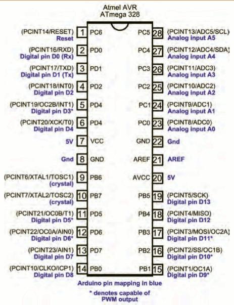

36 The Arduino Microcontroller: Atmel ARV Atmega 328 Specification

37 What is the Arduino todbot.com/blog/bionicarduino
38 Getting Started Check out: 1. Download & install the Arduino environment (IDE) 2. Connect the board to your computer via the UBS cable 3. If needed, install the drivers (not needed in lab) 4. Launch the Arduino IDE 5. Select your board 6. Select your serial port 7. Open the blink example 8. Upload the program

39 Try It: Connect the USB Cable todbot.com/blog/bionicarduino

40 Arduino IDE See: for more information


41 Select Serial Port and Board

42 Status Messages todbot.com/blog/bionicarduino
43 todbot.com/blog/bionicarduino
44 Data Representation Typically computers store and transmit information digitally as a collection of bits. Each bit has two states: on/off true/false high/low 1/0 A byte is a collection of 8 bits (usually) An 8-bit byte can encode 256 different states
45 Data Representation Information is coded using a predefined method Consider the coding for three bits Eight district values Many options for encoding

46 Data Representation Information is coded using a predefined method Consider the coding for three bits Eight district values Many options for encoding
47 Data Representation Information is coded using a predefined method Consider the coding for three bits Eight district values Many options for encoding
48 Data Representation Information is coded using a predefined method Consider the coding for three bits Eight district values Many options for encoding A B C D F P W I
49 Arduino Basics Data Types boolean Unsigned Integers single bit FALSE/TRUE (really uses a whole byte of memory) byte eight bits 0 to 255 word two bytes 0 to unsigned long 4 bytes 0 to 4,294,967,295 Signed Integers char eight bits -128 to 127 short two bytes -32,768 to 32,767 long 4 bytes -2,147,483,648 to 2,147,483,647.

50 Arduino Basics Data Types int Unsigned integer, the number of bytes used depends on the particular hardware used. For us int is the same as short. Real Numbers float Floating point number uses 4 bytes. Used for non-integers has 6-7 decimal point precision E+38 to E+38
51 Arduino Basics Declaring/Initializing Variables Before using a variable it must be declared. int a; // creates an integer with the name a When a variable is declared it can also be initialized. int a=34; // creates an integer with the name a //and assigns it the value 34.
52 Arduino Basics Data Types The char data type is used to represent characters using ASCII encoding. Single character constants are indicated with single quotes. char A; A='B'; 'B' is encoded with ASCII and the resulting value of 66 is stored in A. What does A +! equal?
53 Arduino Basics Data Types A single variable can store an array of values. The index is contained in square brackets. Arrays are zero indexed (start at zero). int threeints[3]; // threeints is an array (0-2) threeints[0]=15; threeints[1]=10; threeints[2]=threeints[0]-threeints[1];
54 Arduino Basics Data Types An array of characters is called a string char examplestring[8]; examplestring= arduino ; The last element of a sting is always the null string which has an ASCII value of zero
55 Arduino Basics Data Types Stings can also be stored as objects using the String class. Using String objects rather than character arrays uses more memory but adds functionality. Character arrays are referred to as strings with a small s, and instances of the String class are referred to as Strings with a capital S. Constant strings, specified in "double quotes" are treated as char arrays, not instances of the String class.

56 Arduino Basics Functions Creating functions allows for modular program design which speeds up the programming process and makes it easy to debug and/or modify the functionality of a program


57 Add an External LED to pin 13 File > Examples > Digital > Blink LED s have polarity Negative indicated by flat side of the housing and a short leg

58 A Little Bit About Programming Code is case sensitive Statements are commands and must end with a semi-colon Comments follow a // or begin with /* and end with */ loop and setup

59 Our First Program
60 Terminology
61 Setup() Description La fonction setup() est appelée au démarrage du programme. Cette fonction est utilisée pour initialiser les variables, le sens des broches, les librairies utilisées. La fonction setup n'est exécutée qu'une seule fois, après chaque mise sous tension ou reset (réinitialisation) de la carte Arduino. Syntaxe void setup() { } Exemple int buttonpin = 3; // déclaration d'une variable globale void setup() // fonction setup - début de l'exécution du programme { Serial.begin(9600); pinmode(buttonpin, INPUT); } void loop() // fonction loop - est exécutée en boucle // une fois que la fonction setup a été exécutée { //... } Commentaire La fonction setup(), même vide, est obligatoire dans tout programme Arduino Pour comprendre : les habitués du C seront surpris de ne pas trouver la classique fonction main() obligatoire dans tout programme C. En fait, la fonction setup() et la fonction loop()sont implémentées au sein de la fonction main() (Voir dans le répertoire arduino le fichier \hardware\cores\arduino\main.cxx) qui est appelée en premier lors de l'exécution de tout programme en C, langage sur lequel est basé le langage Arduino.
62 Commentaire La fonction loop() est obligatoire, même vide, dans tout programme. loop() Description Après avoir créé une fonction setup(), qui initialise et fixe les valeurs de démarrage du programme, la fonction loop () (boucle en anglais) fait exactement ce que son nom suggère et s'exécute en boucle sans fin, permettant à votre programme de s'exécuter et de répondre. Utiliser cette fonction pour contrôler activement la carte Arduino. Syntaxe void loop() { } Exemple int buttonpin = 3; // la fonction setup initialise la communication série // et une broche utilisée avec un bouton poussoir void setup() { beginserial(9600); pinmode(buttonpin, INPUT); } // la fonction loop teste l'état du bouton à chaque passage // et envoie au PC une lettre H si il est appuyé, L sinon. void loop() { if (digitalread(buttonpin) == HIGH) serialwrite('h ); else serialwrite('l'); delay(1000); }
63 Arduino Basics Program Flow Control: Conditional Statements and Branching Conditional Statements if (condition){ } else{ } //do this if condition is true //do this if condition is false Condition is often a statement that uses comparison operators ==,!=, <,> Common mistake is to use = instead of ==
64 Arduino Basics Program Flow Control: Loops for loop for (initialization; condition; increment){ //do this until the condition is no longer met } Example for(int i=0;i<3;i++){ serial.println(i); } Serial.println(i);
65 Arduino Basics Variable scope int hi; int there=0; //global variables //all functions have access void setup(){ } int this=10; //only exists within setup() hi=1; void loop(){ } println( hi ); //changing value of hi //prints hi println(hi); //prints 1 println(there); //prints 0 println(this); //variable not defined error program //won t compile (verify)
66 Arduino Basics Example: What is the final value of x? int x=1; void setup(){ x=10; } void loop(){ if (x<20){ for(int i=1;i<3;i++){ x=x+x; } } }
67 Serial Communication First you need to setup serial communication Serial.begin(9600); //typically in setup() 9600 is the default speed but different values can be used. Two main functions for printing information on the computer. Serial.print( Hi ); //Prints the word Hi on the screen. The next print //command will result in printing right after the i Serial.println( Hi ); //will pass a linebreak after Hi. The next print //command will result in printing on a new line. What is printed depends on the data type of the variable being passed to the function.
68 Serial Communication Information can be read from the computer (serial monitor) Bytes are stored in a buffer automatically Serial.read(); //reads first byte from buffer Serial.available();// returns the number of bytes in the buffer Serial.flush();// clears the buffer
69 Arduino Digital Output //There is a LED connected to pin 13 on the //RedBoard Digital output pins can be HIGH (5V) or LOW (0V). Before you use a digital output you need to set the pinmode void setup() { pinmode(13, OUTPUT); } // sets pin 13 as output void loop() { digitalwrite(13, HIGH); // sets the LED on delay(1000); // waits for a second digitalwrite(13, LOW); // sets the LED off delay(1000); // waits for a second }
70 Arduino Digital Input int ledpin = 13; // LED connected to digital pin 13 int inpin = 7; // pushbutton connected to digital pin 7 boolean val = 0; // variable to store the read value Digital input pins can be HIGH (2.7V-5V) or LOW (1.2V-0V). Before you use a digital input you need to set the pinmode void setup() { pinmode(ledpin, OUTPUT); // sets the digital pin 13 as output pinmode(inpin, INPUT); // sets the digital pin 7 as input } void loop() { val = digitalread(inpin); // read the input pin digitalwrite(ledpin, val); // sets the LED to the button's value }
71 Arduino Digital Input int ledpin = 13; // LED connected to digital pin 13 int inpin = 7; // pushbutton connected to digital pin 7 boolean val = 0; // variable to store the read value void setup() { pinmode(ledpin, OUTPUT); // sets the digital pin 13 as output pinmode(inpin, INPUT); // sets the digital pin 7 as input } void loop() { val = digitalread(inpin); // read the input pin digitalwrite(ledpin, val); // sets the LED to the button's value }
72 Arduino Digital Input Pins Configured as INPUT_PULLUP The Atmega chip on the Arduino has internal pull-up resistors (resistors that connect to power internally) that you can access. If you prefer to use these instead of external pulldown resistors, you can use the INPUT_PULLUP argument in pinmode().
73 Arduino Analog Input Analog Signal Value is continuous not discretized Analog Inputs allow us to read analog voltage signals but first we have to discretize them. The RedBoard (and UNO) have a 10-bit analog to digital converter A/D Voltages from 0V to 5V are scaled to the integers from 0 to 1023
74 Arduino Analog Input int analogpin = 3; // potentiometer wiper (middle terminal) // connected to analog pin 3 // outside leads to ground and +5V int val = 0; // variable to store the value read void setup() { Serial.begin(9600); } // setup serial void loop() { val = analogread(analogpin); Serial.println(val); } // read the input pin // debug value
 Pins marked with ~ can be used as analog output pins The analogwrite")
75 Arduino Output The RedBoard (like other Arduino boards) does not have a true analog output. Instead it can create a pulse width modulation (PWM) signal on designated pins PWM Turns on and off rapidly. Duty cycle of the pulse can be adjusted, which controls the average power output of the pin (dimmer switches work the same way) Pins marked with ~ can be used as analog output pins The analogwrite function takes two inputs: The pin number and a value between 0 and 255 (8-bit)
76 Arduino Output int ledpin = 9; // LED connected to digital pin 9 int analogpin = 3; // potentiometer connected to analog pin 3 int val = 0; // variable to store the read value void setup() { pinmode(ledpin, OUTPUT); // sets the pin as output } void loop() { val = analogread(analogpin); // read the input pin analogwrite(ledpin, val / 4); }
77 Arduino Output int ledpin = 9; // LED connected to digital pin 9 int analogpin = 3; // potentiometer connected to analog pin 3 int val = 0; // variable to store the read value void setup() { pinmode(ledpin, OUTPUT); // sets the pin as output } void loop() { val = analogread(analogpin); // read the input pin analogwrite(ledpin, val / 4); // analogread values go from 0 to 1023, analogwrite values from 0 to 255 }

78 Digital I/0 pinmode(pin, mode) Sets pin to either INPUT or OUTPUT digitalread(pin) Reads HIGH or LOW from a pin digitalwrite(pin, value) Writes HIGH or LOW to a pin Electronic stuff Output pins can provide 40 ma of current Writing HIGH to an input pin installs a 20KΩ pullup
79 Arduino Timing delay(ms) Pauses for a few milliseconds delaymicroseconds(us) Pauses for a few microseconds More commands: arduino.cc/en/reference/homepage
80 Digital? Analog? Digital has two values: on and off Analog has many (infinite) values Computers don t really do analog, they quantize Remember the 6 analog input pins---here s how they work todbot.com/blog/bionicarduino


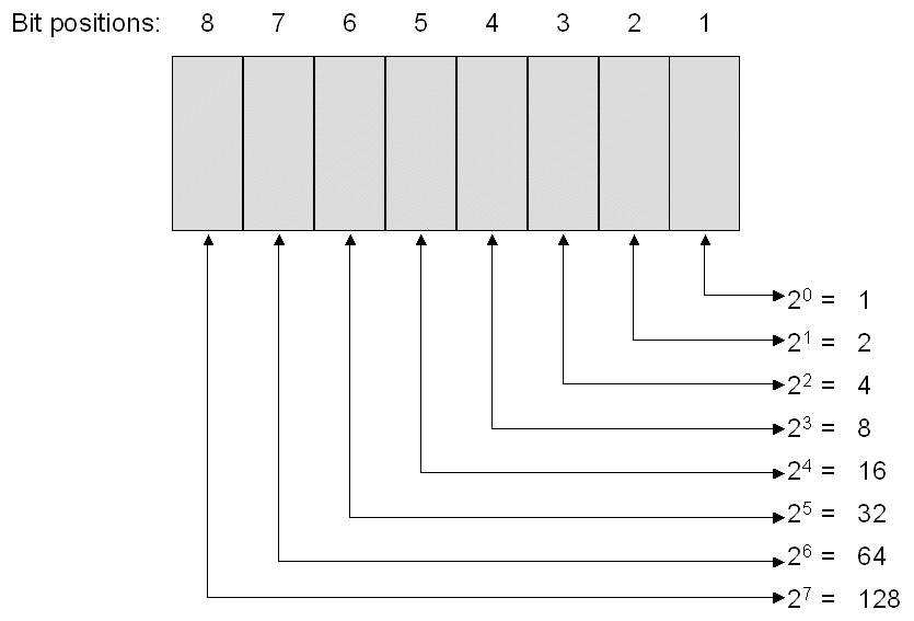
81 Bits and Bytes

82 Variables www3.ntu.edu.sg

83 Putting It Together Complete the sketch (program) below. What output will be generated by this program? What if the schematic were changed?
84 Good References
The Von Neumann Architecture. Designing Computers. The Von Neumann Architecture. CMPUT101 Introduction to Computing - Spring 2001
 The Von Neumann Architecture Chapter 5.1-5.2 Von Neumann Architecture Designing Computers All computers more or less based on the same basic design, the Von Neumann Architecture! CMPUT101 Introduction
Designing Computers. The Von Neumann Architecture. The Von Neumann Architecture. The Von Neumann Architecture
 Chapter 5.1-5.2 Designing Computers All computers more or less based on the same basic design, the Von Neumann Architecture! Von Neumann Architecture CMPUT101 Introduction to Computing (c) Yngvi Bjornsson
CMPUT101 Introduction to Computing - Summer 2002
 7KH9RQ1HXPDQQ$UFKLWHFWXUH Chapter 5.1-5.2 Von Neumann Architecture 'HVLJQLQJ&RPSXWHUV All computers more or less based on the same basic design, the Von Neumann Architecture! CMPUT101 Introduction to Computing
The Von Neumann Architecture Odds and Ends. Designing Computers. The Von Neumann Architecture. CMPUT101 Introduction to Computing - Spring 2001
 The Von Neumann Architecture Odds and Ends Chapter 5.1-5.2 Von Neumann Architecture CMPUT101 Introduction to Computing (c) Yngvi Bjornsson & Vadim Bulitko 1 Designing Computers All computers more or less
CMPUT101 Introduction to Computing - Summer 2002
 7KH9RQ1HXPDQQ$UFKLWHFWXUH 2GGVDQG(QGV Chapter 5.1-5.2 Von Neumann Architecture CMPUT101 Introduction to Computing (c) Yngvi Bjornsson & Vadim Bulitko 1 'HVLJQLQJ&RPSXWHUV All computers more or less based
CS 265. Computer Architecture. Wei Lu, Ph.D., P.Eng.
 CS 265 Computer Architecture Wei Lu, Ph.D., P.Eng. Part 3: von Neumann Architecture von Neumann Architecture Our goal: understand the basics of von Neumann architecture, including memory, control unit
Computer Architecture (part 2)
") Computer Architecture (part 2) Topics: Machine Organization Machine Cycle Program Execution Machine Language Types of Memory & Access 2 Chapter 5 The Von Neumann Architecture 1 Arithmetic Logic Unit (ALU)
Computer Architecture (part 2) Topics: Machine Organization Machine Cycle Program Execution Machine Language Types of Memory & Access 2 Chapter 5 The Von Neumann Architecture 1 Arithmetic Logic Unit (ALU)
FUNCTIONS For controlling the Arduino board and performing computations.
 d i g i t a l R e a d ( ) [Digital I/O] Reads the value from a specified digital pin, either HIGH or LOW. digitalread(pin) pin: the number of the digital pin you want to read HIGH or LOW Sets pin 13 to
Arduino Prof. Dr. Magdy M. Abdelhameed
 Course Code: MDP 454, Course Name:, Second Semester 2014 Arduino What is Arduino? Microcontroller Platform Okay but what s a Microcontroller? Tiny, self-contained computers in an IC Often contain peripherals
COMPUTER SYSTEM. COMPUTER SYSTEM IB DP Computer science Standard Level ICS3U. COMPUTER SYSTEM IB DP Computer science Standard Level ICS3U
 C A N A D I A N I N T E R N A T I O N A L S C H O O L O F H O N G K O N G 5.1 Introduction 5.2 Components of a Computer System Algorithm The Von Neumann architecture is based on the following three characteristics:
CS1004: Intro to CS in Java, Spring 2005
 CS1004: Intro to CS in Java, Spring 2005 Lecture #10: Computer architecture Janak J Parekh janak@cs.columbia.edu HW#2 due Tuesday Administrivia Mass Storage RAM is volatile Not useful for permanent storage,
Introduction to Arduino. Wilson Wingston Sharon
 Introduction to Arduino Wilson Wingston Sharon cto@workshopindia.com Physical computing Developing solutions that implement a software to interact with elements in the physical universe. 1. Sensors convert
Chapter 5 12/2/2013. Objectives. Computer Systems Organization. Objectives. Objectives (continued) Introduction. INVITATION TO Computer Science 1
 Introduction. INVITATION TO Computer Science 1") Chapter 5 Computer Systems Organization Objectives In this chapter, you will learn about: The components of a computer system Putting all the pieces together the Von Neumann architecture The future: non-von
Chapter 5 Computer Systems Organization Objectives In this chapter, you will learn about: The components of a computer system Putting all the pieces together the Von Neumann architecture The future: non-von
Computer Architecture
 Computer Architecture Topics: Machine Organization Machine Cycle Program Execution Machine Language Types of Memory & Access Von Neumann Design 1) Two key ideas 1) The stored program concept 1) instructions
Chapter 5: Computer Systems Organization. Invitation to Computer Science, C++ Version, Third Edition
 Chapter 5: Computer Systems Organization Invitation to Computer Science, C++ Version, Third Edition Objectives In this chapter, you will learn about: The components of a computer system Putting all the
Chapter 5: Computer Systems Organization
 Objectives Chapter 5: Computer Systems Organization Invitation to Computer Science, C++ Version, Third Edition In this chapter, you will learn about: The components of a computer system Putting all the
Arduino Part 2. Introductory Medical Device Prototyping
 Introductory Medical Device Prototyping Arduino Part 2, http://saliterman.umn.edu/ Department of Biomedical Engineering, University of Minnesota More Arduino Programming Digital I/O (Read/Write) Analog
Lab 01 Arduino 程式設計實驗. Essential Arduino Programming and Digital Signal Process
 Lab 01 Arduino 程式設計實驗 Essential Arduino Programming and Digital Signal Process Arduino Arduino is an open-source electronics prototyping platform based on flexible, easy-to-use hardware and software. It's
The CPU and Memory. How does a computer work? How does a computer interact with data? How are instructions performed? Recall schematic diagram:
 The CPU and Memory How does a computer work? How does a computer interact with data? How are instructions performed? Recall schematic diagram: 1 Registers A register is a permanent storage location within
More Arduino Programming
 Introductory Medical Device Prototyping Arduino Part 2, http://saliterman.umn.edu/ Department of Biomedical Engineering, University of Minnesota More Arduino Programming Digital I/O (Read/Write) Analog
CMPUT 101 with Solutions Quiz 2 (50 minutes) August 7, 2002
 August 7, 2002") CMPUT 101 with Solutions Quiz 2 (50 minutes) August 7, 2002 Last Name: First Name: Section: Instructor: B1 I. E. Leonard Instructions: Read carefully before proceeding. No calculators, books or other aids
CMPUT 101 with Solutions Quiz 2 (50 minutes) August 7, 2002 Last Name: First Name: Section: Instructor: B1 I. E. Leonard Instructions: Read carefully before proceeding. No calculators, books or other aids
FUNCTIONS USED IN CODING pinmode()
") FUNCTIONS USED IN CODING pinmode() Configures the specified pin to behave either as an input or an output. See the description of digital pins for details on the functionality of the pins. As of Arduino
FUNCTIONS USED IN CODING pinmode() Configures the specified pin to behave either as an input or an output. See the description of digital pins for details on the functionality of the pins. As of Arduino
CMPUT 101 with Solutions Quiz 2 (50 minutes) November 16, 2000
 November 16, 2000") CMPUT 101 with Solutions Quiz 2 (50 minutes) November 16, 2000 Last Name: First Name: Section: Instructor: A6 Yngvi Bjornsson Instructions: Read carefully before proceeding. No calculators, books or other
CMPUT 101 with Solutions Quiz 2 (50 minutes) November 16, 2000 Last Name: First Name: Section: Instructor: A6 Yngvi Bjornsson Instructions: Read carefully before proceeding. No calculators, books or other
Arduino Uno Microcontroller Overview
 Innovation Fellows Program Arduino Uno Microcontroller Overview, http://saliterman.umn.edu/ Department of Biomedical Engineering, University of Minnesota Arduino Uno Power & Interface Reset Button USB
IME-100 Interdisciplinary Design and Manufacturing
 IME-100 Interdisciplinary Design and Manufacturing Introduction Arduino and Programming Topics: 1. Introduction to Microprocessors/Microcontrollers 2. Introduction to Arduino 3. Arduino Programming Basics
A Review of Chapter 5 and. CSc 2010 Spring 2012 Instructor: Qian Hu
 A Review of Chapter 5 and Chapter 6 Chapter 5 Computer Systems Organization Von Neumann Architecture 4 Components Memory Input/output ALU Control Unit Two major features Stored program concept Sequential
TANGIBLE MEDIA & PHYSICAL COMPUTING INTRODUCTION TO ARDUINO
 TANGIBLE MEDIA & PHYSICAL COMPUTING INTRODUCTION TO ARDUINO AGENDA ARDUINO HARDWARE THE IDE & SETUP BASIC PROGRAMMING CONCEPTS DEBUGGING & HELLO WORLD INPUTS AND OUTPUTS DEMOS ARDUINO HISTORY IN 2003 HERNANDO
Note. The above image and many others are courtesy of - this is a wonderful resource for designing circuits.
 Robotics and Electronics Unit 2. Arduino Objectives. Students will understand the basic characteristics of an Arduino Uno microcontroller. understand the basic structure of an Arduino program. know how
Adapted from a lab originally written by Simon Hastings and Bill Ashmanskas
 Physics 364 Arduino Lab 1 Adapted from a lab originally written by Simon Hastings and Bill Ashmanskas Vithayathil/Kroll Introduction Last revised: 2014-11-12 This lab introduces you to an electronic development
Introduction to Microcontrollers Using Arduino. PhilRobotics
 Introduction to Microcontrollers Using Arduino PhilRobotics Objectives Know what is a microcontroller Learn the capabilities of a microcontroller Understand how microcontroller execute instructions Objectives
University of Portland EE 271 Electrical Circuits Laboratory. Experiment: Arduino
 University of Portland EE 271 Electrical Circuits Laboratory Experiment: Arduino I. Objective The objective of this experiment is to learn how to use the Arduino microcontroller to monitor switches and
IME-100 ECE. Lab 3. Electrical and Computer Engineering Department Kettering University. G. Tewolde, IME100-ECE,
 IME-100 ECE Lab 3 Electrical and Computer Engineering Department Kettering University 3-1 1. Laboratory Computers Getting Started i. Log-in with User Name: Kettering Student (no password required) ii.
Chapter 2 The Basic Functions
 Chapter 2 The Basic Functions 2.1 Overview The code you learn to write for your Arduino is very similar to the code you write in any other computer language. This implies that all the basic concepts remain
5 Computer Organization
 5 Computer Organization 5.1 Foundations of Computer Science ã Cengage Learning Objectives After studying this chapter, the student should be able to: q List the three subsystems of a computer. q Describe
Introduction to Arduino
 Introduction to Arduino Paco Abad May 20 th, 2011 WGM #21 Outline What is Arduino? Where to start Types Shields Alternatives Know your board Installing and using the IDE Digital output Serial communication
CS 101, Mock Computer Architecture
 CS 101, Mock Computer Architecture Computer organization and architecture refers to the actual hardware used to construct the computer, and the way that the hardware operates both physically and logically
CMPUT 101 with Solutions Quiz 2 (50 minutes) November 7, 2003
 November 7, 2003") CMUT 101 with Solutions Quiz 2 (50 minutes) November 7, 2003 Last Name: First Name: Section: Instructor: A1 I. E. Leonard Instructions: Read carefully before proceeding. No calculators, books or other
CMUT 101 with Solutions Quiz 2 (50 minutes) November 7, 2003 Last Name: First Name: Section: Instructor: A1 I. E. Leonard Instructions: Read carefully before proceeding. No calculators, books or other
 Chapter 1 Microprocessor architecture ECE 3120 Dr. Mohamed Mahmoud http://iweb.tntech.edu/mmahmoud/ mmahmoud@tntech.edu Outline 1.1 Computer hardware organization 1.1.1 Number System 1.1.2 Computer hardware
Computer Organization
 INF 101 Fundamental Information Technology Computer Organization Assistant Prof. Dr. Turgay ĐBRĐKÇĐ Course slides are adapted from slides provided by Addison-Wesley Computing Fundamentals of Information
Procedure: Determine the polarity of the LED. Use the following image to help:
 Section 2: Lab Activity Section 2.1 Getting started: LED Blink Purpose: To understand how to upload a program to the Arduino and to understand the function of each line of code in a simple program. This
arduino programming notebook brian w. evans revised by Paul Badger
 arduino programming notebook brian w. evans revised by Paul Badger Arduino Programming Notebook Written and compiled by Brian W. Evans With information or inspiration taken from: http://www.arduino.cc
Dec Hex Bin ORG ; ZERO. Introduction To Computing
 Dec Hex Bin 0 0 00000000 ORG ; ZERO Introduction To Computing OBJECTIVES this chapter enables the student to: Convert any number from base 2, base 10, or base 16 to any of the other two bases. Add and
Information Science 1
 Information Science 1 -Basic Concepts of Computers: Opera4on, Architecture, Memory- Week 02 College of Information Science and Engineering Ritsumeikan University Today s lecture outline l Recall the previous
Robotics/Electronics Review for the Final Exam
 Robotics/Electronics Review for the Final Exam Unit 1 Review. 1. The battery is 12V, R1 is 400 ohms, and the current through R1 is 20 ma. How many ohms is R2? ohms What is the voltage drop across R1? V
Diskrečioji matematika
 Diskrečioji matematika www.mif.vu.lt/~algis Basic structures Introduction program euclid (input, output); var x,y: integer; function gcd (u,v: integer): integer; var t: integer; begin repeat if u
Level 2: The Hardware World Chapters 4 and 5 (topics of other cs courses)
") Level 2: The Hardware World Chapters 4 and 5 (topics of other cs courses) Invitation to Computer Science, Java Version, Third Edition Chapter 4: The Building Blocks: Binary Numbers, Boolean Logic, and
Level 2: The Hardware World Chapters 4 and 5 (topics of other cs courses) Invitation to Computer Science, Java Version, Third Edition Chapter 4: The Building Blocks: Binary Numbers, Boolean Logic, and
Machine Architecture. or what s in the box? Lectures 2 & 3. Prof Leslie Smith. ITNP23 - Autumn 2014 Lectures 2&3, Slide 1
 Machine Architecture Prof Leslie Smith or what s in the box? Lectures 2 & 3 ITNP23 - Autumn 2014 Lectures 2&3, Slide 1 Basic Machine Architecture In these lectures we aim to: understand the basic architecture
Smart Objects. SAPIENZA Università di Roma, M.Sc. in Product Design Fabio Patrizi
 Smart Objects SAPIENZA Università di Roma, M.Sc. in Product Design Fabio Patrizi 1 What is a Smart Object? Essentially, an object that: Senses Thinks Acts 2 Example 1 https://www.youtube.com/watch?v=6bncjd8eke0
Fall Harris & Harris
 E11: Autonomous Vehicles Fall 2011 Harris & Harris PS 1: Welcome to Arduino This is the first of five programming problem sets. In this assignment you will learn to program the Arduino board that you recently
5 Computer Organization
 5 Computer Organization 5.1 Foundations of Computer Science Cengage Learning Objectives After studying this chapter, the student should be able to: List the three subsystems of a computer. Describe the
The Arduino Briefing. The Arduino Briefing
 Mr. Yee Choon Seng Email : csyee@simtech.a-star.edu.sg Design Project resources http://guppy.mpe.nus.edu.sg/me3design.html One-Stop robotics shop A-Main Objectives Pte Ltd, Block 1 Rochor Road, #02-608,
CN310 Microprocessor Systems Design
 CN310 Microprocessor Systems Design Microcontroller Nawin Somyat Department of Electrical and Computer Engineering Thammasat University Outline Course Contents 1 Introduction 2 Simple Computer 3 Microprocessor
Arduino 101 AN INTRODUCTION TO ARDUINO BY WOMEN IN ENGINEERING FT T I NA A ND AW E S O ME ME NTO R S
 Arduino 101 AN INTRODUCTION TO ARDUINO BY WOMEN IN ENGINEERING FT T I NA A ND AW E S O ME ME NTO R S Overview Motivation Circuit Design and Arduino Architecture Projects Blink the LED Switch Night Lamp
Lecture Objectives. Introduction to Computing Chapter 0. Topics. Numbering Systems 04/09/2017
 Lecture Objectives Introduction to Computing Chapter The AVR microcontroller and embedded systems using assembly and c Students should be able to: Convert between base and. Explain the difference between
CPU ARCHITECTURE. QUESTION 1 Explain how the width of the data bus and system clock speed affect the performance of a computer system.
 CPU ARCHITECTURE QUESTION 1 Explain how the width of the data bus and system clock speed affect the performance of a computer system. ANSWER 1 Data Bus Width the width of the data bus determines the number
Arduino Uno. Power & Interface. Arduino Part 1. Introductory Medical Device Prototyping. Digital I/O Pins. Reset Button. USB Interface.
 Introductory Medical Device Prototyping Arduino Part 1, http://saliterman.umn.edu/ Department of Biomedical Engineering, University of Minnesota Arduino Uno Power & Interface Reset Button USB Interface
CS 31: Intro to Systems Digital Logic. Kevin Webb Swarthmore College February 3, 2015
 CS 31: Intro to Systems Digital Logic Kevin Webb Swarthmore College February 3, 2015 Reading Quiz Today Hardware basics Machine memory models Digital signals Logic gates Circuits: Borrow some paper if
CS 31: Intro to Systems Digital Logic. Kevin Webb Swarthmore College February 2, 2016
 CS 31: Intro to Systems Digital Logic Kevin Webb Swarthmore College February 2, 2016 Reading Quiz Today Hardware basics Machine memory models Digital signals Logic gates Circuits: Borrow some paper if
EE 3170 Microcontroller Applications
 EE 3170 Microcontroller Applications Lecture 4 : Processors, Computers, and Controllers - 1.2 (reading assignment), 1.3-1.5 Based on slides for ECE3170 by Profs. Kieckhafer, Davis, Tan, and Cischke Outline
CC411: Introduction To Microprocessors
 CC411: Introduction To Microprocessors OBJECTIVES this chapter enables the student to: Use number { base 2, base 10, or base 16 }. Add and subtract binary/hex numbers. Represent any binary number in 2
CN310 Microprocessor Systems Design
 CN310 Microprocessor Systems Design Micro Architecture Nawin Somyat Department of Electrical and Computer Engineering Thammasat University 28 August 2018 Outline Course Contents 1 Introduction 2 Simple
Arduino Programming and Interfacing
 Arduino Programming and Interfacing Stensat Group LLC, Copyright 2017 1 Robotic Arm Experimenters Kit 2 Legal Stuff Stensat Group LLC assumes no responsibility and/or liability for the use of the kit and
CREATED BY M BILAL & Arslan Ahmad Shaad Visit:
 CREATED BY M BILAL & Arslan Ahmad Shaad Visit: www.techo786.wordpress.com Q1: Define microprocessor? Short Questions Chapter No 01 Fundamental Concepts Microprocessor is a program-controlled and semiconductor
BASIC COMPUTER ORGANIZATION. Operating System Concepts 8 th Edition
 BASIC COMPUTER ORGANIZATION Silberschatz, Galvin and Gagne 2009 Topics CPU Structure Registers Memory Hierarchy (L1/L2/L3/RAM) Machine Language Assembly Language Running Process 3.2 Silberschatz, Galvin
Introduction to Computers - Chapter 4
 Introduction to Computers - Chapter 4 Since the invention of the transistor and the first digital computer of the 1940s, computers have been increasing in complexity and performance; however, their overall
ASSEMBLY LANGUAGE MACHINE ORGANIZATION
 ASSEMBLY LANGUAGE MACHINE ORGANIZATION CHAPTER 3 1 Sub-topics The topic will cover: Microprocessor architecture CPU processing methods Pipelining Superscalar RISC Multiprocessing Instruction Cycle Instruction
Microcontrollers. Microcontroller
 Microcontrollers Microcontroller A microprocessor on a single integrated circuit intended to operate as an embedded system. As well as a CPU, a microcontroller typically includes small amounts of RAM and
IME-100 ECE. Lab 4. Electrical and Computer Engineering Department Kettering University. G. Tewolde, IME100-ECE,
 IME-100 ECE Lab 4 Electrical and Computer Engineering Department Kettering University 4-1 1. Laboratory Computers Getting Started i. Log-in with User Name: Kettering Student (no password required) ii.
A B C ((NOT A) AND B) OR C
 AND B) OR C") chapter5 pg 184 1,2,6 1 Assuming that x=1 and y=2, determine the value of each of the following Boolean expressing: (x=1) AND(y=3) (x1) Not[(x=1) AND (y=2)] Answer: False True False 2 Assume
chapter5 pg 184 1,2,6 1 Assuming that x=1 and y=2, determine the value of each of the following Boolean expressing: (x=1) AND(y=3) (x1) Not[(x=1) AND (y=2)] Answer: False True False 2 Assume
Advanced Parallel Architecture Lesson 3. Annalisa Massini /2015
 Advanced Parallel Architecture Lesson 3 Annalisa Massini - 2014/2015 Von Neumann Architecture 2 Summary of the traditional computer architecture: Von Neumann architecture http://williamstallings.com/coa/coa7e.html
EXPERIMENT 7 Please visit https://www.arduino.cc/en/reference/homepage to learn all features of arduino before you start the experiments
 EXPERIMENT 7 Please visit https://www.arduino.cc/en/reference/homepage to learn all features of arduino before you start the experiments TEMPERATURE MEASUREMENT AND CONTROL USING LM35 Purpose: To measure
Computer Architecture 2/26/01 Lecture #
 Computer Architecture 2/26/01 Lecture #9 16.070 On a previous lecture, we discussed the software development process and in particular, the development of a software architecture Recall the output of the
Summary of Computer Architecture
 Summary of Computer Architecture Summary CHAP 1: INTRODUCTION Structure Top Level Peripherals Computer Central Processing Unit Main Memory Computer Systems Interconnection Communication lines Input Output
COMPUTER STRUCTURE AND ORGANIZATION
 COMPUTER STRUCTURE AND ORGANIZATION Course titular: DUMITRAŞCU Eugen Chapter 4 COMPUTER ORGANIZATION FUNDAMENTAL CONCEPTS CONTENT The scheme of 5 units von Neumann principles Functioning of a von Neumann
BASIC ARDUINO WORKSHOP. Mr. Aldwin and Mr. Bernardo
 BASIC ARDUINO WORKSHOP Mr. Aldwin and Mr. Bernardo 1 BASIC ARDUINO WORKSHOP Course Goals Introduce Arduino Hardware and Understand Input Software and Output Create simple project 2 Arduino Open-source
4Serial SIK BINDER //77
 4Serial SIK BINDER //77 SIK BINDER //78 Serial Communication Serial is used to communicate between your computer and the RedBoard as well as between RedBoard boards and other devices. Serial uses a serial
Workshop on Microcontroller Based Project Development
 Organized by: EEE Club Workshop on Microcontroller Based Project Development Presented By Mohammed Abdul Kader Assistant Professor, Dept. of EEE, IIUC Email:kader05cuet@gmail.com Website: kader05cuet.wordpress.com
Chapter 2 Data Manipulation
 Chapter 2 Data Manipulation Dr. Farzana Rahman Assistant Professor Department of Computer Science James Madison University 1 What the chapter is about? 2.1 Computer Architecture 2.2 Machine Language 2.3
ARDUINO. By Kiran Tiwari BCT 2072 CoTS.
 ARDUINO By Kiran Tiwari BCT 2072 CoTS www.kirantiwari.com.np SO What is an Arduino? WELL!! Arduino is an open-source prototyping platform based on easy-to-use hardware and software. Why Arduino? Simplifies
Computer Systems. Binary Representation. Binary Representation. Logical Computation: Boolean Algebra
 Binary Representation Computer Systems Information is represented as a sequence of binary digits: Bits What the actual bits represent depends on the context: Seminar 3 Numerical value (integer, floating
Von Neumann Architecture
 Von Neumann Architecture Assist lecturer Donya A. Khalid Lecture 2 2/29/27 Computer Organization Introduction In 945, just after the World War, Jon Von Neumann proposed to build a more flexible computer.
Computer Organization
 Objectives 5.1 Chapter 5 Computer Organization Source: Foundations of Computer Science Cengage Learning 5.2 After studying this chapter, students should be able to: List the three subsystems of a computer.
Chapter One. Introduction to Computer System
 Principles of Programming-I / 131101 Prepared by: Dr. Bahjat Qazzaz -------------------------------------------------------------------------------------------- Chapter One Introduction to Computer System
Microcontrollers and Interfacing week 8 exercises
 2 HARDWARE DEBOUNCING Microcontrollers and Interfacing week 8 exercises 1 More digital input When using a switch for digital input we always need a pull-up resistor. For convenience, the microcontroller
Computer System Overview OPERATING SYSTEM TOP-LEVEL COMPONENTS. Simplified view: Operating Systems. Slide 1. Slide /S2. Slide 2.
 BASIC ELEMENTS Simplified view: Processor Slide 1 Computer System Overview Operating Systems Slide 3 Main Memory referred to as real memory or primary memory volatile modules 2004/S2 secondary memory devices
COSC 122 Computer Fluency. Computer Organization. Dr. Ramon Lawrence University of British Columbia Okanagan
 COSC 122 Computer Fluency Computer Organization Dr. Ramon Lawrence University of British Columbia Okanagan ramon.lawrence@ubc.ca Key Points 1) The standard computer (von Neumann) architecture consists
Serial.begin ( ); Serial.println( ); analogread ( ); map ( );
; Serial.println( ); analogread ( ); map ( );") Control and Serial.begin ( ); Serial.println( ); analogread ( ); map ( ); A system output can be changed through the use of knobs, motion, or environmental conditions. Many electronic systems in our world
Control and Serial.begin ( ); Serial.println( ); analogread ( ); map ( ); A system output can be changed through the use of knobs, motion, or environmental conditions. Many electronic systems in our world
Counter & LED (LED Blink)
") 1 T.R.E. Meeting #1 Counter & LED (LED Blink) September 17, 2017 Contact Info for Today s Lesson: President Ryan Muller mullerr@vt.edu 610-573-1890 Learning Objectives: Learn how to use the basics of Arduino
1 T.R.E. Meeting #1 Counter & LED (LED Blink) September 17, 2017 Contact Info for Today s Lesson: President Ryan Muller mullerr@vt.edu 610-573-1890 Learning Objectives: Learn how to use the basics of Arduino
Computer System Overview
 Computer System Overview Operating Systems 2005/S2 1 What are the objectives of an Operating System? 2 What are the objectives of an Operating System? convenience & abstraction the OS should facilitate
ECE2049: Embedded Computing in Engineering Design A Term Fall Lecture #9: Exam Review w/ Solutions
 ECE2049: Embedded Computing in Engineering Design A Term Fall 2018 Lecture #9: Exam Review w/ Solutions Reading for Today: Review all reading and notes, Davies Ch 1, 2, 4,7, MSP430 User's Guide Ch 6.1,
<Table of content> <Parts and description> <Circuit board Guide> <Pins> <Basics of Coding> <Intro to Arduino> <Intro> <Downloading Arduino IDO>
 http://www.arduino.cc/
Arduino 07 ARDUINO WORKSHOP 2007
 ARDUINO WORKSHOP 2007 PRESENTATION WHO ARE WE? Markus Appelbäck Interaction Design program at Malmö University Mobile networks and services Mecatronics lab at K3, Malmö University Developer, Arduino community
ArdOS The Arduino Operating System Quick Start Guide and Examples
 ArdOS The Arduino Operating System Quick Start Guide and Examples Contents 1. Introduction... 1 2. Obtaining ArdOS... 2 3. Installing ArdOS... 2 a. Arduino IDE Versions 1.0.4 and Prior... 2 b. Arduino
COMP2121: Microprocessors and Interfacing. Instruction Set Architecture (ISA)
") COMP2121: Microprocessors and Interfacing Instruction Set Architecture (ISA) http://www.cse.unsw.edu.au/~cs2121 Lecturer: Hui Wu Session 2, 2017 1 Contents Memory models Registers Data types Instructions
COMP2121: Microprocessors and Interfacing Instruction Set Architecture (ISA) http://www.cse.unsw.edu.au/~cs2121 Lecturer: Hui Wu Session 2, 2017 1 Contents Memory models Registers Data types Instructions
Show how to connect three Full Adders to implement a 3-bit ripple-carry adder
 Show how to connect three Full Adders to implement a 3-bit ripple-carry adder 1 Reg. A Reg. B Reg. Sum 2 Chapter 5 Computing Components Yet another layer of abstraction! Components Circuits Gates Transistors
Introduction to Microcontrollers
 Introduction to Microcontrollers Embedded Controller Simply an embedded controller is a controller that is embedded in a greater system. One can define an embedded controller as a controller (or computer)
Latches. IT 3123 Hardware and Software Concepts. Registers. The Little Man has Registers. Data Registers. Program Counter
 IT 3123 Hardware and Software Concepts Notice: This session is being recorded. CPU and Memory June 11 Copyright 2005 by Bob Brown Latches Can store one bit of data Can be ganged together to store more
COMPUTER ORGANISATION CHAPTER 1 BASIC STRUCTURE OF COMPUTERS
 Computer types: - COMPUTER ORGANISATION CHAPTER 1 BASIC STRUCTURE OF COMPUTERS A computer can be defined as a fast electronic calculating machine that accepts the (data) digitized input information process
A3 Computer Architecture
 A3 Computer Architecture Engineering Science 3rd year A3 Lectures Prof David Murray david.murray@eng.ox.ac.uk www.robots.ox.ac.uk/ dwm/courses/3co Michaelmas 2000 1 / 1 2: Introduction to the CPU 3A3 Michaelmas
1 Digital tools. 1.1 Introduction
 1 Digital tools 1.1 Introduction In the past few years, enormous advances have been made in the cost, power, and ease of use of microcomputers and associated analog and digital circuits. It is now possible,