EasyBuild- Assembly Manual. Enclosure for Desktop CNC /3D Systems STEPCRAFT 600/ 840
|
|
|
- Delilah Baker
- 6 years ago
- Views:
Transcription
1 EasyBuild- Assembly Manual Enclosure for Desktop CNC /3D Systems STEPCRAFT 600/ 840 Original assembly manual date of


. Stepcraft has taken extreme care to ensure the correctness of the information contained in this manual.")

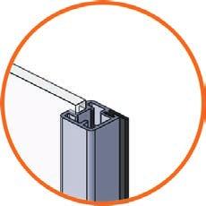
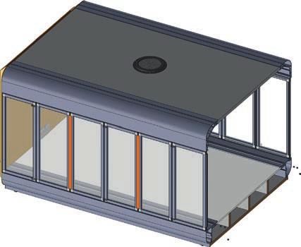
2 Dear customer, thank you very much for purchasing our high-quality kit of an enclosure of your Stepcraft Desktop CNC /3D System. This manual will take you through every step of the assembly. Please read the entire manual carefully before starting assembly. This way, you obtain an overview of the steps require which will help you avoid unneccessary mistakes. Please take care to use the the correct parts in the correct orientation as some parts differ only minimally. Please let a second person assist you in the assembly. Before beginning the assembly process, please verify that you have all of the required parts in your kit using the list below. Stepcraft provides video support with certain assembly steps. Simply scan the related QR code with your smartphone. If you do not have a smartphone, please enter the following URL in your web browser: (replace xx-xx with the number under the QR code). Stepcraft has taken extreme care to ensure the correctness of the information contained in this manual. We accept no liability for damage in materials or injury to persons caused by assembling the enclosure. You are responsible for the safe operation of your Stepcraft Desktop CNC /3D System and its accessories. Content of the construction kit (illustrations are not true to scale) 1 enclosure front panel 2 3 enclosure rear panel upper profile 2x lower profile front door profile bottom/ top lateral pane profile vertical without handle 413 mm 2x 2x 18x 7 lateral pane profile vertical with handle 411 mm 8 lateral pane profile horizontal 9 front pane profile vertical without handle 374 mm 600: 114 mm 840: 157 mm 6x 24x 6x

 2x 600: 95 mm 840: 140 mm")
 13")


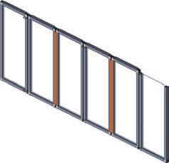
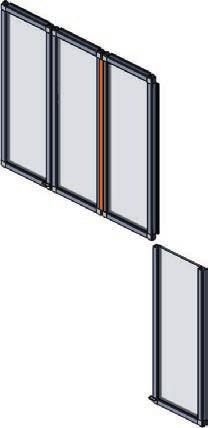
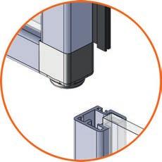
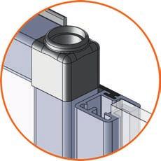
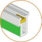
3 front pane profile vertical with handle 372 mm front pane profile horizontal rubber seal (silicone) 2x 600: 95 mm 840: 140 mm 8x 600: 6,00 m 840: 7,50 m connection profile (silicone) 13 orange 600: 2,1 m 840: 2,1 m 14 side pane 15 front pane black 600: 3,4 m 840: 3,4 m 600: 420 x 121 mm 840: 420 x 164 mm 12x 600: 381 x 102 mm 840: 381 x 147 mm 4x base plate 600: 583 x 898,5 mm 840: 763 x 1156,5 mm base plate partition 600: 2x 840: 3x machine table 600: 454 x 898,5 mm 840: 634 x 1156,5 mm top plate 600: 435 x 898,5 mm 840: 615 x 1156,5 mm plastic corner circular brush 70x strip brush cable outlet slot nut, lockable slot nut, loose slot nut, loose external pivot pin 6x 10x 6x 32x


4 door handle pressure pin plastic foot socket head screw, M6 x 30 mm socket head screw, M5 x 30 mm 16x 16x 4x 4x 6x flange screw, M5 x 12 mm flange screw, M6 x 20 mm set screw, M4 x 5 mm locking nut, M5 spacer M3 x 10 mm 2x 20x 6x 6x 2x spacer, M5 x 50 mm button head cap screw, M3 x 6 mm wooden dowel cam lock screw cam screw 4x 600: 4x 840: 6x 600: 4x 840: 6x 600: 4x 840: 6x end switch with cable supply cable conduit 6/4 mm emergency switch emergency switch cable controller board 3x 600: 3,30 m 840: 4,30 m 600: 1,11 m 840: 1,35 m hole plug 8 mm hole plug 36 mm 15 pin Sub-D cable wood screw 3,5 x 15 mm grounding cable set incl. serrated lock washer 3x

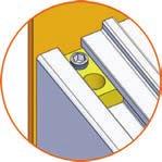
5 Explanation of symboles and details: 1 = assembly phase A = assembly group 1 = work step = view of assembly phase = required parts for this work step = larger detailed view/ pre-assembly of parts = Tighten the screw. = Engage the screw, but do not tighten. = Caution Work particularly careful. = Tighten clockwise. = Remove protection film and affix self-adhesive part. = Fasten part with superglue, use sparingly, must not get on bearing or running surface. = Deburring. = Apply dish liquid as shown in picture. Required tools and materials: - Needle file (supplied) - Spanner 5,5 mm - Allen wrench 2,0 mm - Spanner 8 mm - Allen wrench 3,0 mm - Rubber mallet - Allen wrench 4,0 mm - Crosstip screwdriver - Allen wrench 5,0 mm - Superglue Differences in the assembly size 300 and 420: The illustrations in this assembly manual are exemplary and are based on the enclosure for size 840. Please pay attention to the different dimensions of the individual parts

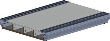
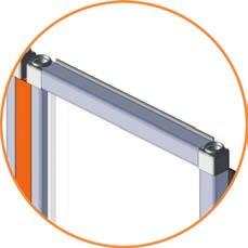
6 1 Base frame A x 2x Size 600: Please produce 2x Size 840: Please produce 2x : 4x 840: 6x


7 1.2 A 600: 2x 840: 3x x x 4x

8 B B


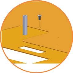
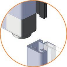
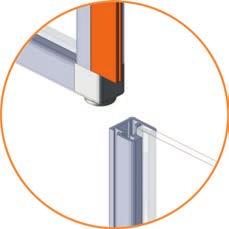
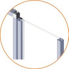
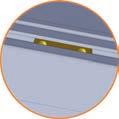
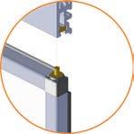
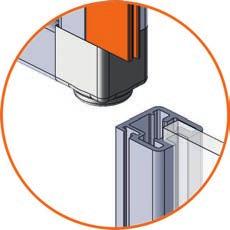
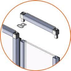
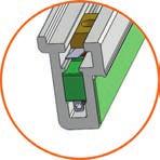
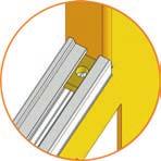
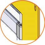
9 1.6 B B 33 6x Preparatory steps for all doors: Before attaching the plastic corners it is especially important that the leading edges of all profiles are deburred with the supplied needle file in order to avoid blocking due to plastic chips.


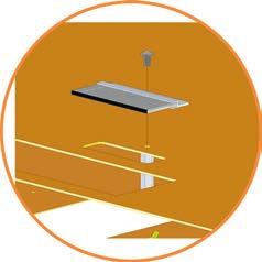
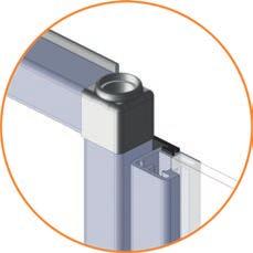
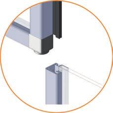
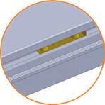
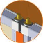
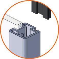
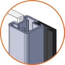
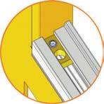
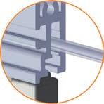
10 C : 114 mm 840: 157 mm Please pay attention to the correct length 114/ 157 mm For an easier assembly of the plastic corners, please turn the profile and use the rubber mallet to fix it to the corner C : 114 mm 840: 157 mm C2 20 Please produce 24x


11 D 27 C mm Please pay attention to the correct length 411 mm D mm Please pay attention to the correct length 413 mm D2 14 Please produce 2x


12 E C mm Please pay attention to the correct length 413 mm E mm Please pay attention to the correct length 413 mm E2 14 Please produce 2x


13 F C mm Please pay attention to the correct length 413 mm F mm Please pay attention to the correct length 413 mm F2 14 Please produce 2x


14 G C mm Please pay attention to the correct length 413 mm G mm Please pay attention to the correct length 411 mm G2 14 Please produce 2x
15 H C mm Please pay attention to the correct length 413 mm H mm Please pay attention to the correct length 413 mm H2 14 Please produce 2x

16 I C mm Please pay attention to the correct length 413 mm I mm Please pay attention to the correct length 411 mm I2 14 Please produce 2x
 2.1 D 12 415 mm 2.")
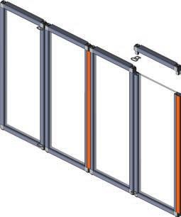
17 2 2 x D E F G H I Side doors (produce 2x) 2.1 D mm mm
18 2.3 C E mm
19 2.6 C 2.7 F mm


20 2.9 C 2.10 G mm


21 2.12 C 2.13 H mm


22 2.15 C 2.16 I mm

23 2.18 C x 3x x 3x Please produce 2x


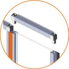
24 3 Upper frame x 3.2 2


25 x x


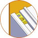
26 3.6 Please repeat worksteps 3.1 to 3.5 for the right of the enclose in a mirror-inverted way Please pay attention to the dimension of the top plate x
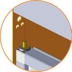
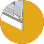
27 J : 95 mm 840: 140 mm Please pay attention to the correct length 95/ 140 mm For an easier assembly of the plastic corners, please turn the profile and use the rubber mallet to fix it to the corner J : 96 mm 840: 141 mm J2 20 Please produce 8x
28 K 27 J mm Please pay attention to the correct length 372 mm K mm Please pay attention to the correct length 374 mm K2 14
29 L J mm Please pay attention to the correct length 374 mm L mm Please pay attention to the correct length 374 mm L2 14
30 M J mm Please pay attention to the correct length 374 mm M mm Please pay attention to the correct length 374 mm M2 14
31 N J mm Please pay attention to the correct length 374 mm N mm Please pay attention to the correct length 372 mm N2 14
32 4 K L M N Front door 4.1 K mm mm


33 4.3 J L mm


34 4.6 J 4.7 M mm


35 4.9 J 4.10 N mm


36 4.12 J x 2x x 2x


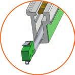
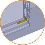
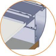
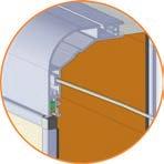
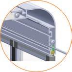
37 O P P1 Guide the cable end firstly through the cable conduit and afterwards carefully through the profile : 1450 mm 840: 1950 mm


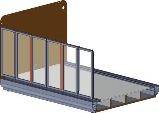
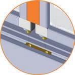
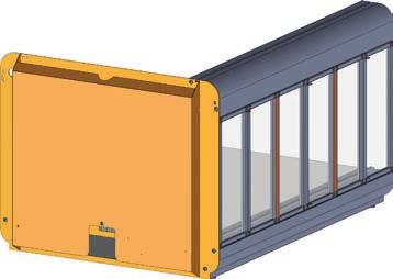
38 5 Enclosure front O Please degrease the surface first


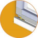

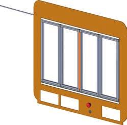
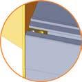
39 5.3 P 4 Please degrease the surface first


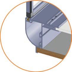
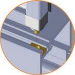
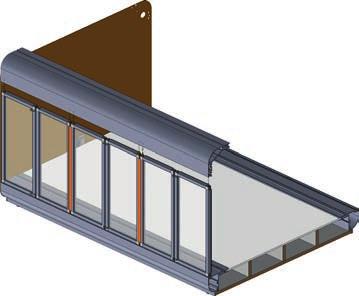
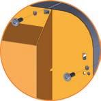
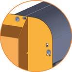
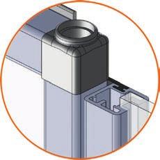
40 6 Final assembly x Guide the cable end firstly through the cable conduit and afterwards carefully through the profile. 2x 600: 898 mm 840: 1156 mm

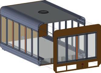
41 x


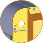
 LED Switch (opt.")
42 x 2x 6.7 Insertion tool/ Switch-Box Emergency stop Desktop CNC /3D System LED Power (opt.) LED Switch (opt.) 12V Power (opt.) Door right Coor left Door front


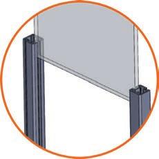
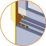
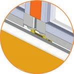
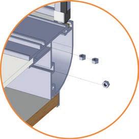
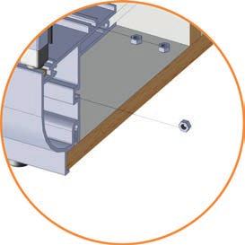
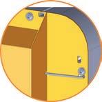
43 x x With the socket head screws M5 x 30 mm the Stepcraft Desktop CNC /3D System, control units or the Switch-Box and drawers can be fixed in their final position in the enclosure.
44 Stepcraft GmbH & Co. KG An der Beile Menden Germany Tel: +49 (2373) Fax: +49 (2373) info@stepcraft-systems.com Stepcraft 2017
EasyBuild- Assembly Manual. Enclosure for Desktop CNC /3D Systems STEPCRAFT 300/ 420
 EasyBuild- Assembly Manual Enclosure for Desktop CNC /3D Systems STEPCRAFT 300/ 420 Original assembly manual date of 01.07.2017 Dear customer, thank you very much for purchasing our high-quality kit of
Assembly and Setup Manual
 M-11 Series Copyboard/C-11 Series Captureboard Assembly and Setup Manual This is the installation and assembly manual for the M-11 series/c-11 series. To the Customer Specialized techniques are required
INSTALLATION INSTRUCTIONS
 INSTALLATION INSTRUCTIONS 19 20 21 01 07 22 23 13 10 12 08 17 18 11 02 14 15 04 03 16 WELCOME PARTS LIST Thank you for purchasing this HealthPoint Technology Cabinet from Humanscale! Before you begin installing
TABLE OF CONTENTS SECTION 1 TABLETOP CONFIGURATION SECTION 2 TABLETOP CONFIGURATION ACCESSORIES SECTION 3 SLIDE CONFIGURATION
 S6 USER S MANUAL TABLE OF CONTENTS SECTION 1 TABLETOP CONFIGURATION SECTION 2 TABLETOP CONFIGURATION ACCESSORIES SECTION 3 SLIDE CONFIGURATION SECTION 4 SLIDE CONFIGURATION ACCESSORIES SECTION 5 RACK MOUNT
Description: Detailed procedure on removing old bushing and installing new Brake Bushing Replacement Kit 10447
 Procedure: BRAKE BUSHING REPLACEMENT PROCEDURE Product: Document #: Rev: Page: MODEL 7000, 7000A, & 8000 GYRO 078 1 1 of 14 Description: Detailed procedure on removing old bushing and installing new Brake
INSTRUCTIONS FOR THE INSTALLATION OF THE INFINITY "L" DISPLAY HOOD (INTO PREVIOUSLY INSTALLED INFINITY "L" SYSTEMS)
") Doc. 6001025 Rev B INSTRUCTIONS FOR THE INSTALLATION OF THE INFINITY "L" DISPLAY HOOD (INTO PREVIOUSLY INSTALLED INFINITY "L" SYSTEMS) Rev. B Doc. 6001025 Page 1 of 13 IMPORTANT NOTICE This document covers
Doc. 6001025 Rev B INSTRUCTIONS FOR THE INSTALLATION OF THE INFINITY "L" DISPLAY HOOD (INTO PREVIOUSLY INSTALLED INFINITY "L" SYSTEMS) Rev. B Doc. 6001025 Page 1 of 13 IMPORTANT NOTICE This document covers
C764i Integrated LCD Screen Option. Cardio Theater Integrated Bracket Assembly Instructions
 C764i Integrated LCD Screen Option Cardio Theater Integrated Bracket Assembly Instructions Table of Contents 1 2 3 4 5 6 7 Before You Begin... 3 Obtaining Service... 3 Unpacking the Equipment... 3 Important
Outdoor PTZ. Mounting on the Ceiling Using Pendant Mount. Installation Guide. For Models: I93, I94, I95, I96, KCM /12/03
 Outdoor PTZ Mounting on the Ceiling Using Pendant Mount For Models: I93, I94, I95, I96, KCM-8211 2013/12/03 Table of Contents Mounting Solutions... 3 Straight Tube Installation Procedures... 4 Step 1:
IBM. Rack Installation Instructions
 IBM Rack Installation Instructions Review the documentation that comes with your rack cabinet for safety and cabling information. When installing your server in a rack cabinet, consider the following:
Q2 XBee Handheld Controller Assembly Guide
 Q2 XBee Handheld Controller Assembly Guide Copyright Quantum Robotics Inc. Q2 Controller V1.0 1 Parts List: The kit comes with 14 individual bags. 1. Case Top and Bottom 2. Case Screw Package containing:
G12/G12x USER S MANUAL
 G12/G12x USER S MANUAL TABLE OF CONTENTS SECTION 1 SLIDE CONFIGURATION SECTION 2 SLIDE CONFIGURATION ACCESSORIES SECTION 3 TABLETOP CONFIGURATION SECTION 4 TABLETOP CONFIGURATION ACCESSORIES SECTION 5
Installation Guide Philips MP20/30/40/50/60/70 IntelliVue M-Series Arm Rail Mount Kit
 Installation Guide Philips MP20/30/40/50/60/70 IntelliVue M-Series Arm Rail Mount Kit The purpose of this guide is to: 1. Describe attachment of Table Top Mount to Mounting Adapter on Arm (page 2). 2.
Installation Guide for DV8 Off-Road Tailgate-Mounted Tire Carrier (18-19 Jeep Wrangler JL)
") Installation Guide for DV8 Off-Road Tailgate-Mounted Tire Carrier (18-19 Jeep Wrangler JL) Installation Time: 1 Hour Tools Required Trim removal tool (plastic or wood to prevent scratches on the paint)
Installation Guide for DV8 Off-Road Tailgate-Mounted Tire Carrier (18-19 Jeep Wrangler JL) Installation Time: 1 Hour Tools Required Trim removal tool (plastic or wood to prevent scratches on the paint)
Treadmill Integrated LCD Screen Option. Cardio Theater Integrated Bracket Assembly Instructions
 Treadmill Integrated LCD Screen Option Cardio Theater Integrated Bracket Assembly Instructions Table of Contents 1 2 3 4 5 6 Before You Begin... 4 Obtaining Service... 4 Unpacking the Equipment... 4 Important
PDC / ECIS. Display Update update with conversion kit Display Update. Contents. General information. Important notes.
 US Toll Free: 800.BODE.TEC BodeTechnicalServices.com Display Update PDC / ECIS Display Update update with conversion kit 535268 Contents General information Important notes Requirements Conversion instructions
CHAPTER 5 UNIT MAINTENANCE INSTRUCTIONS
 FPU SYSTEMS OPERATION MANUAL (INCLUDING REPAIR PARTS & SPECIAL TOOL LIST) STANDARD AND SPECIALIZED FPU MODULES BOH FPU Field Pack-up Units CHAPTER 5 UNIT MAINTENANCE INSTRUCTIONS BOH-PM-0-5 06 BOH Environmental
Assembly Manual for Mobile X-ray
 Suitable for Kodak 2000, Kodak 2100, Kodak 2200 and Trophy Elytis - 12 th January 2011 William Green Page 1 of 8 Printed 12/01/2011, 2:07:42 PM Mobile X-ray Parts List 1. 6 x M10 x 65mm UNB CAP Bolts 2.
CLIMB2 DUAL MONITOR SIT/STAND WORKSTATION
 CLIMB2 DUAL MONITOR SIT/STAND WORKSTATION CLIMB2 Rev A 3/17 Model CLIMB2-SLV ASSEMBLY AND ADJUSTMENT CLIMB2 PARTS AND TOOLS PLEASE REVIEW these instructions before beginning the assembly and adjustment
Warning Before Installation
 Warning Before Installation English Power off the Network Camera as soon as smoke or unusual odors are detected. Refer to your user's manual for the operating temperature. Contact your distributor in the
Tech Tub Premium: Holds Up to 10 Tablets
 TEC1000 Tech Tub Premium: Holds Up to 10 Tablets Assembly Guide TEC1000_2017_A Check out our other products online at www.copernicused.com For assistance, please contact us: 1-800-267-8494 Email info@copernicused.com
Floppy Disk To USB. Converter Installation and. Operation Manual
 Floppy Disk To USB Converter Installation and Operation Manual Kit Price $125.00 Plus Shipping Why Should I Change My Floppy Drive To A USB Drive? You won't ever need floppies anymore and yet you'll be
Cycles Integrated LCD Screen Option. Cardio Theater Integrated Bracket Assembly Instructions
 Recumbent Upright Cycles Integrated LCD Screen Option Cardio Theater Integrated Bracket Assembly Instructions Table of Contents 1 2 3 4 5 6 7 Before You Begin... 4 Obtaining Service... 4 Unpacking the
Ultra short throw lens installation
 Ultra short throw lens installation The ultra short throw lens 0.36 UST GS (P/N: 140-133108-XX) allows you to position your projector as close as possible to your screen or display. Unless otherwise indicated,
INSTALLATION GUIDE 02-ES ESTC
 02-ES7341-47 01-140316-01 01-140251-01 01-140162-01 01-140296-01 01-140220-01 01-ESTC01-02 01-140305-01 3.0mm Galvanised Fixed Strap M8 x 35mm Broaching Stud Z/P M8 x 25mm x 1.6mm washer Z/P M8 Nylon Insert
INSTALLATION MANUAL. LO SIDE BOX ADD-ON KIT For driver or passenger side configurations TRUCK STORAGE SOLUTIONS FOR THE WAY YOU WORK
 TRUCK STORAGE SOLUTIONS FOR THE WAY YOU WORK INSTALLATION MANUAL LO SIDE BOX ADD-ON KIT For driver or passenger side configurations Model: QDKSBDO1 -or- QDKSBP01 Part No. 24-0327 Rev. A ECN 5430 ATTENTION:
Installation Instructions
 Second Kit for the GrandSTAR Jukebox Kit #26694913 Purpose: These instructions outline the procedures to install a second 1000W into the GrandSTAR jukebox with the AV controller (shown) or the 4 Channel
DIGITAL Server Rackmount Installation Guide
 DIGITAL Server Rackmount Installation Guide Part Number: ER-PCSRA-IA. E01 Digital Equipment Corporation December 1997 The information in this document is subject to change without notice and should not
Charging Cabinet Owner s Manual
 by edugear Charging Cabinet Owner s Manual Before using, please read these operating instructions carefully. They contain important advice concerning the use and safety of your Charging Cabinet. The Charging
Replacing the Encoder Strip
 6-1-11. Replacing the Encoder Strip The following describes the procedure for replacing the Encoder Strip. Refer to the diagram below for identifying the parts and their positions. (The numbers shown in
I/O Expansion Board. Control Made Simple
 ? Control Made Simple I/O Expansion Board West Coast Office 1263 El Camino Real Menlo Park, CA 94025 Phone (650) 853-1444? Fax (650) 853-1405 www.flashcutcnc.com Midwest Office 444 Lake Cook Road, Suite
E1135C PDU and Pod Upgrade Procedure
 E4030-90010 Rev. B 12/2003 In this Document... Tools Needed, 2 Contents of the Upgrade Kits, 2 Installation Procedures, 4 Verifying the Power Option of the New PDU, 4 Removing the PDU from the Support
Print Head Replacement and Adjustment Guide for the CD Printer Revision C
 Print Head Replacement and Adjustment Guide for the CD Printer 110488-001 Revision C Rimage is the trademark of the Rimage Corporation. Perfect Image is a registered trademark of the Rimage Corporation.
User Manual CARFIT Modular System Series CMB
 User Manual CARFIT Modular System Series CMB Table of contents Contents CARFIT Modular System CMB 3 Installation Instructions Example Multimedia Unit Cover 6 1 Mounting support 1 and support 2 7 2 Mounting
Assembly and Setup Manual
 M-12 Series Copyboard / C-12 Series Captureboard Assembly and Setup Manual This is the installation and assembly manual for the M-12 series Copyboard and C-12 series Captureboard. (The copyboard and/or
Project 8.1 Model A Button Maker
 Project 8.1 Model A Button Maker Introduction Interpreting dimensioned drawings is an important engineering skill. Using drawings to create a computer model of a part or product is also important. Communicating
Installation Guide for Mazak Mazatrol M - Plus, M-2, M32, T-Plus, T2
 1 Installation Guide for Mazak Mazatrol M - Plus, M-2, M32, T-Plus, T2 Tsubis Part Number: LCD12-0046 Power Down 1. Power down the controller. 2. Power down the complete machine by turning off the rear
INSTALLATION MANUAL DATAVAULT DATAVAULT - BARE JOBSITE STORAGE SOLUTIONS
 JOBSITE STORAGE SOLUTIONS ALWAYS ON THE JOB INSTALLATION MANUAL 118-01 DATAVAULT 118-02 DATAVAULT - BARE Werner Co. 724-588-2000 93 Werner Rd. 888-523-3371 toll free/ llamada gratuita Greenville, PA 16125
System Storage EXP3000 Rack Installation Instructions
 System Storage EXP3000 Rack Installation Instructions Review the documentation that comes with your rack cabinet for safety and cabling information. When you install the IBM System Storage EXP3000 in a
Flat Panel Static Wall Mount MSP-SS (GSM-210)
") INSTALLATION INSTRUCTIONS Flat Panel Static Wall Mount (GSM-2) The static wall mount fits most 23 to 30 displays. The mount was designed to adapt to the VESA 75mm/0mm, 0mm/0mm, and 200mm/0mm compliant
INSTALLATION INSTRUCTIONS Flat Panel Static Wall Mount (GSM-2) The static wall mount fits most 23 to 30 displays. The mount was designed to adapt to the VESA 75mm/0mm, 0mm/0mm, and 200mm/0mm compliant
CDCR 5020s SYSTEM. Service Manual. Ver
 CDCR 5020s SYSTEM Service Manual Ver. 040608 2 CR-Tech is marketing the CDCR5020s, an innovation in the field of compact desktop portable Computed Radiography Technologies designed for low-volume clinics.
Rack Installation Instructions
 Rack Installation Instructions Review the documentation that comes with your rack cabinet for safety and cabling information. When installing your server in a rack cabinet, consider the following: v Two
Probably the fastest enclosure in the world
 95 9 enclosure system Probably the fastest enclosure in the world Sample configuration tools required no no tools required Vitaro can be assembled within less than 60 seconds. 00:00 00:0 00:08 00: 00:5
FortiCam FD40 Mounting Guide
 FortiCam FD40 Mounting Guide 1 FORTINET DOCUMENT LIBRARY http://docs.fortinet.com FORTINET VIDEO GUIDE http://video.fortinet.com FORTINET BLOG https://blog.fortinet.com CUSTOMER SERVICE & SUPPORT https://support.fortinet.com
7" Touch Screen Display
 7" Touch Screen Display Installation Guide Contents Minimum Requirements...1 Select a Location...1 Initial Setup...2 Unboxing...2 Installation...3 Prepare the Panel...3 Install the Mounting Plate...3 Mount
3G Cell Modem Installation and User Guide
 3G Cell Modem Installation and User Guide For BaseStation 1000 & BaseStation 3200 Irrigation Controllers in X and XS Cabinets April 24, 2017 Customer Service 1-866-294-5847 Baseline Inc. www.baselinesystems.com
Ag Leader Technology Insight. Direct Command Installation Spra-Coupe 7000 Series
 Note: Indented items indicate parts included in an assembly listed above. Part Name / Description Part Number Quantity Direct Command Spra-Coupe 7000 Kit 4100531 1 Liquid Product Control Module 4000394
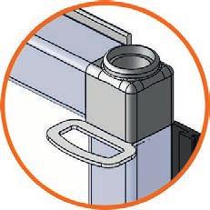
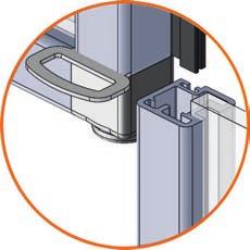
Accessories for control enclosures. BERNSTEIN attachment solutions. Double coupling head (console version with suspension system attachment)
") 25 Accessories for control enclosures BERNSTEIN attachment Single coupling head (suspended console version) Double coupling head (console version with suspension system attachment) 322.5 231 232 140 The
25 Accessories for control enclosures BERNSTEIN attachment Single coupling head (suspended console version) Double coupling head (console version with suspension system attachment) 322.5 231 232 140 The
Adapter Kit for PanelView 1200/1200e Touch Screen Terminal Cutout
 Installation Instructions Adapter Kit for PanelView 1200/1200e Touch Screen Terminal Cutout Catalog Numbers 2711-NR5T, 2711P-RAT12E2 Topic Page About This Publication 1 Important User Information 2 About
FE8171V. 3MP 360 Panoramic View Vandal-proof
 FE8171V 3MP 360 Panoramic View Vandal-proof Warning Before Installation English Power off the Network Camera as soon as smoke or unusual odors are detected. Refer to your user's manual for the operating
Installation and Assembly: 2 x 2 Video Wall Ceiling Mount for 40" - 55" flat Panel Displays
 Installation and Assembly: 2 x 2 Video Wall Ceiling Mount for 40" - 55" flat Panel Displays Model: DS-VWT955-2X2 EXTENSION COLUMN (SOLD SEPARATELY) COMPATIBILITY Display width must be a minimum of 36"
MK-212 SERIES PARTS LIST MODELS: MK Part # MK SPCL Part # SPCL MK Part #
 www.mkdiamond.com MK-1 SERIES PARTS LIST MODELS: MK-1- Part # 191 MK-1--SPCL Part # 191-SPCL MK-1-6 Part # 16 MK-1- Part # 191 MK-1-6 Part # 16 Revision 100 1.016 Manual Part No. 196-PM Caution: Read all
Installing a Power over Ethernet injector
 Installing a Power over Ethernet injector AlphaEclipse StreetSmart and RoadStar signs The instructions in this document explain how to install/replace a Power over Ethernet (PoE) injector in a StreetSmart
Warning Before Installation. Package Contents EN - 1. Refer to your user's manual for the operating temperature.
 510000221G Warning Before Installation English Power off the Network Camera as soon as smoke or unusual odors are detected. Do not place the Network Camera on unsteady surfaces. Do not insert sharp or
ANIxx. Installation Manual.
 ANIxx Installation Manual www.audac.eu Introduction WaveDynamics Dante audio network interface The ANIxx are Dante audio network interfaces for use with WaveDynamics supporting amplifiers, supporting two
LARGE S URGE-PROTECTOR S HELTER
 LARGE S URGE-PROTECTOR S HELTER The weather-resistant Large Surge-Protector Shelter (simply referred to as the shelter in this manual) provides protection from the elements for Surge Protectors (not included)
Quick Start Guide V5.1.
 Quick Start Guide V5.1 1 Quick Start Guide Table of Content 1. Package Contents...1 2. Cautions... 1 3. System Requirements... 1 4. Hardware Overview... 2 4.1 Mini Dome Network Camera...2 4.2 IR Mini
Digital Menu Board Wall Mount Installation Instructions
 Digital Menu Board Wall Mount Installation MDSWMB2T4249 MDSWMB3T4249 www.microndisplaysolutions.com Table of Contents Important Safety... 3 Models and Specifications... 4 Package Contents... 5 Step 1 Two(2)
Assembly Instructions for #5630 Medication PalWOW
 Assembly Instructions for #5630 Medication PalWOW Before assembling, please familiarize yourself with all the parts and check to make sure you have all the parts as listed below. A B A & B - The box in
TECHKNOW, INC. Kiosk Order Confirmation System INSTALLATION MANUAL. Revision Date: July 11, 2012 Part # Version 3.2
 document Page 1 of 18 TECHKNOW, INC Kiosk Order Confirmation System INSTALLATION MANUAL Revision Date: July 11, 2012 Part # Version 3.2 Techknow, Inc. 393 Mayfield Road Duncan, SC 29334 www.gotechknow.com
Warning Before Installation. Package Contents EN - 1. Refer to your user s manual for the operating temperature.
 5000020G Warning Before Installation English Power off the Network Camera as soon as smoke or unusual odors are detected. Do not place the Network Camera on unsteady surfaces. Do not insert sharp or tiny
Dual TV/Monitor Desk Mount Stand (Duplex Series) Model: DE9E2S-S
 Model: DE9E2S-S") Dual TV/Monitor Desk Mount Stand (Duplex Series) Model: DE9E2S-S Instruction Manual Images may different from actual product Disclaimer It is Dyconn s intention to have all the correct information represented
Dual TV/Monitor Desk Mount Stand (Duplex Series) Model: DE9E2S-S Instruction Manual Images may different from actual product Disclaimer It is Dyconn s intention to have all the correct information represented
INSTALLATION INSTRUCTIONS:
 INSTALLATION INSTRUCTIONS: Part # SV-5600 PC-F Full Frame Type (Black or Chrome) Part # SV-5500 PC-B Top Bar Type (Black or Chrome) Part # SV- PK Kits with PlateCam and 3.5 LCD monitor FEATURES: Revolutionary
DI-ACRO #24 HAND SHEAR INSTRUCTION MANUAL
 DI-ACRO #24 HAND SHEAR INSTRUCTION MANUAL REV. G 6/12 1 TABLE OF CONTENTS A. SAFETY INFORMATION PG. 3 B. SET UP PROCEDURE PG. 3 C. MAINTENANCE PG. 3 D. TECHNICAL DATA PG. 3 E. OPERATING PROCEDURES PG.
Assembly Guide. LEDs. With these assembly instructions, you can easily build your own SWT16. All required components are included in this kit.
 Assembly Guide With these assembly instructions, you can easily build your own SWT16. All required components are included in this kit. You need the following tools: soldering iron, wire cutter and solder.
SEQUEL 6051/6052 LIFT DESK
 SEQUEL 6051/6052 customerservice@ OWNER S MANUAL Product Registration Registering your new BDI product allows us to send you important product updates, service information and helpful hints related to
AirLink GX Series X-Card Installation Guide
 This installation is to be performed only by certified Sierra Wireless AirLink distributors. If it is performed by anyone other than the certified AirLink distributor, the terms of the warranty agreement
Printhead Replacement and Adjustment Guide for the CD Printer Revision B
 Printhead Replacement and Adjustment Guide for the CD Printer 110553-001 Revision B Rimage Corporation 7725 Washington Avenue South Minneapolis, MN 55439 FAX: (952) 946-4578 Service:(800) 382-8436 (North
A-dec 570L Dental Light on a DCS System INSTALLATION GUIDE
 A-dec 570L Dental Light on a DCS System INSTALLATION GUIDE C ONTENTS Choose an Installation Guide...... Before You Begin.............. 3 Disconnect the Light Cable........ 3 Cut the Light Cable............
EV Charging Pole EVT EVT ground mounted
 RAK 85 20.4.202 EV Charging Pole EVT60. EVT60.2 ground mounted EG Installation instruction ME04 ESTO EECTRIC VEHICE CHARGIG POE GROUD MOUTED BEFORE ISTAATIO Remove the components that are put inside the
P F
 12430 55 TH ST N OAK PARK HEIGHTS, MN 55082 P 651-342-1756 F 651-342-1293 INFO@DIACRO.COM Copyright 2014 REV. 9-MAY-2014 1 SAFETY INFORMATION PG. 3 SET-UP PROCEDURE PG. 3 MAINTENANCE PG. 3 TECHNICAL DATA
CDRPanP. Installation. Instructions for Instrumentarium OP-100 FOR PANORAMIC SYSTEMS. Schick Technologies, Inc. Avenue
 P P Avenue CDRPanP FOR PANORAMIC SYSTEMS Installation Instructions for Instrumentarium OP-100 Schick Technologies, Inc. th 31-00 47P Long Island City, New York 11101 (718) 937-5765 (718) 937-5962 (FAX)
TH ST N OAK PARK HEIGHTS, MN P F
 12430 55 TH ST N OAK PARK HEIGHTS, MN 55082 P 651-342-1756 F 651-342-1293 INFO@DIACRO.COM SAFETY INFORMATION PG. 3 SET UP PROCEDURE PG. 3 MAINTENANCE PG. 3 TECHNICAL DATA PG. 3 OPERATING PROCEDURES PG.
Rack Installation Instructions
 Rack Installation Instructions For System Storage EXP2512 and EXP2524 Express Storage Enclosures Use the instructions in this document to install an IBM System Storage EXP2512 Express Storage Enclosure
SNOWBOARD RACK KIT P/N APPLICATION BEFORE YOU BEGIN KIT CONTENTS. Instr Rev Page 1 of 25
 SNOWBOARD RACK KIT P/N 2881251 APPLICATION Pro Ride RMK 155 and 163, Axys RMK 155, 163, and 174 BEFORE YOU BEGIN Read these instructions and check to be sure all parts and tools are accounted for. Please
267/269 Additional Instructions. Assembly of DAC eco
 267/269 Additional Instructions Assembly of DAC eco IMPORTANT READ CAREFULLY BEFORE USE KEEP FOR FUTURE REFERENCE All rights reserved. Property of Dürkopp Adler AG and protected by copyright. Any reuse
Microscopic Imaging Research Station (MIRS) Assembly Guide. Version 1.0.0
 Assembly Guide. Version 1.0.0") Microscopic Imaging Research Station (MIRS) Assembly Guide www.adsyscontrols.com Adsys Controls, Inc.2012 Version 1.0.0 I. Assembly of the Adsys Controls MIRS system This document explains the assembly
Microscopic Imaging Research Station (MIRS) Assembly Guide www.adsyscontrols.com Adsys Controls, Inc.2012 Version 1.0.0 I. Assembly of the Adsys Controls MIRS system This document explains the assembly
Navigator II INstallatIoN MaNUal For static and PaN/tIlt configurations
 Navigator II Installation MANUAL For Static and Pan/Tilt Configurations Document Number: 432-0001-00-12, rev 100 FLIR Systems, Inc., 2008. All rights reserved worldwide. No parts of this manual, in whole
Zero Gravity Rig Operating Instructions
 Welcome to our new top-of-the-line shoulder support system for cameras up to 15 lbs - the ZG Rig. In addition to its totally unique vertical balancing mechanism, this system is designed to be configurable
Megatouch FORCE Monitor Chassis Board Replacement
 Megatouch FORCE Monitor Chassis Board Replacement Visit the Merit Industries, Inc. Web site http://www.meritind.com merit industries, inc. PM0337-01 Rev C Table of Contents FORCE Classic Monitor Chassis
Arecont Vision HSG2 Installation Manual
 0 P age HSG2 Installation Manual A. Arecont Vision HSG2 Housing B. Flat washer C. Spring washer D. Machine screw E. Two (2) rubber plugs F. RJ45 Cable G. Two-sided hexagonal wrench 2. Open the HSG2 housing
Mounting on the Ceiling Using Flush Mount (Face Down)
") Mounting on the Ceiling Using Flush Mount (Face Down) Installation Guide 2014/02/14 Table of Contents Safety Information... 3 Installation Procedures... 5 Step 1: Drill a Hole on the Ceiling... 5 Step
Mounting on the Ceiling Using Flush Mount (Face Down) Installation Guide 2014/02/14 Table of Contents Safety Information... 3 Installation Procedures... 5 Step 1: Drill a Hole on the Ceiling... 5 Step
FIELD MODIFICATION INSTRUCTION. CryoICE BOX Option For AtriCure ORLab ASC1 (400mm) Carts P B
 Carts P B") FIELD MODIFICATION INSTRUCTION CryoICE BOX Option For AtriCure ORLab ASC1 (400mm) Carts P000843.B CAUTION: Federal (U.S.A.) law restricts this device to sale by or on the order of a physician. Information
FIELD MODIFICATION INSTRUCTION CryoICE BOX Option For AtriCure ORLab ASC1 (400mm) Carts P000843.B CAUTION: Federal (U.S.A.) law restricts this device to sale by or on the order of a physician. Information
CS50 Chain Saw UT B Page 1 of 17 Accessories
 CS50 Chain Saw UT-10710-B Page 1 of 17 Accessories CS50 Chain Saw UT-10710-B Page 2 of 17 Accessories A02177 1 BUMPER SPIKE KIT 7031099 1 S RUBBER TUBING (10') 18453 1 /P GREASE-Multi-Purpose (Sprocket
Cone Beam Volumetric Tomography and Panoramic Dental Imaging System
 Installation Manual Installation Manual Installation Manual Installation Manual Installation Manual Cone Beam Volumetric Tomography and Panoramic Dental Imaging System Gendex CB-500 Installation Manual
DIGITAL OBSERVATION GUARD LOW PROFILE PAN TILT KIT USER MANUAL
 DIGITAL OBSERVATION GUARD LOW PROFILE PAN TILT KIT USER MANUAL Version 2.1 June 4, 2013 0 Table of Contents Low Profile Pan Tilt Kit Description... 3 Low Profile Pan Tilt Unit Basic Operation... 4 Mounting
Macintosh PowerBook 165c Motherboard Replacement
 Macintosh PowerBook 165c Motherboard Replacement This guide will demonstrate how to replace the Macintosh PowerBook 165c Motherboard. Written By: John ifixit CC BY-NC-SA www.ifixit.com Page 1 of 15 INTRODUCTION
How to assemble and disassemble Anafi
 How to assemble and disassemble Anafi Prerequisites The best way to repair ANAFI is to use Parrot official drones repair kit. You will need the cruciform as well as the Torx 5 (T5) in order to carry out
PT Teleprompter
 Features you need, Prices you want. PT3000 15 Teleprompter User Guide 3903 Stoney Brook Dr. Houston TX 77063 Tel: 1.713.272.8822 Fax: 1.713.995.4994 www. support@ 2009 ikan Corporation. All right reserved.
WORKSHOP EQUIPMENT. Engineers Stud. Flanged Nut. T-Slot Nut. Step Block. Extension Nut. Step Clamp
 GROUP Indexa T-Slot Clamping Kits Designed to save set up time and solve most T-Slot clamping problems. All components are manufactured from S45C (JIS)/CK45 (DIN) grade non-alloy carbon steel, heat treated
* IMPORTANT * REGISTERING YOUR MACHINE
 * IMPORTANT * REGISTERING YOUR MACHINE Thank you for your purchase of the Keyline 994 Laser. Before continuing with machine setup and use, please complete the following; COMPLETE PRODUCT REGISTRATION FORM
N3150 Installation and Setup Instructions
 IBM System Storage N350 Installation and Setup Instructions Covering the N350 model GC27-426-0 Notices Mail comments to: IBM Corporation Attention Department GZW 9000 South Rita Road Tucson, AZ 85744-000
Installation Guide Philips MP60/70 IntelliVue VHM Arm Rail Mount Kit
 Installation Guide Philips MP60/70 IntelliVue VHM Arm Rail Mount Kit The purpose of this guide is to: 1. Describe attachment of Table Top Mount to Mounting Adapter (page 2) 2. Describe attachment of Down
Installation Guide Mounting Kit for Mounting Philips Avalon CTS Cordless Fetal Transducer System on Wall, 2'' Post, Rail, or Slide-on Mounting Plate
 Installation Guide Mounting Kit for Mounting Philips Avalon CTS Cordless Fetal Transducer System on Wall, 2'' Post, Rail, or Slide-on Mounting Plate The purpose of this guide is to: 1. Describe mounting
Installing the Camera
 CHAPTER 2 This chapter provides information and instructions for installing the Cisco Video Surveillance PTZ IP camera, and includes the following topics: Installation Guidelines, page 2-1 Warnings Before
Holz-Her Sliding Table Saw Kit Installation Instructions: For 1243 Rip Kits
 Holz-Her Sliding Table Saw Kit Installation Instructions: For 1243 Rip Kits Please note this installation kit is designed solely for installation on Holz-Her Sliding Panel Saws, Model 1243 (may also fit
AMERICA S PREMIER EXERCISE EQUIPMENT RAB-336. Abdominal / Back Bench. TuffStuff Fitness Equipment, Inc. 46" 61 3/4" 44 1/4"
 A S S E M B L Y I N S T R U C T I O N S 46" 44 1/4" 61 3/4" RAB-336 Abdominal / Back Bench TuffStuff Fitness Equipment, Inc. 25 E. Franklin Avenue Pomona, CA 91766, USA Ph: 909-629-1600 Fax: 909-629-4967
IBM Systems. Quick start guide for IBM System p5 505 ( )
") IBM Systems Quick start guide for IBM System p5 505 (9115-505) 1 Before you begin This Quick start guide contains an abbreviated set of setup instructions designed to help you quickly unpack and set up
IBM Systems Quick start guide for IBM System p5 505 (9115-505) 1 Before you begin This Quick start guide contains an abbreviated set of setup instructions designed to help you quickly unpack and set up
CDRPan. Installation. Instructions for Planmeca / PM 2002 CC / EC FOR PANORAMIC SYSTEMS
 CDRPan FOR PANORAMIC SYSTEMS Installation Instructions for Planmeca / PM 2002 CC / EC Schick Technologies, Inc. 31-00 47 th Avenue Long Island City, New York 11101 (718) 937-5765 (718) 937-5962 (FAX) Part
INSTALLATION MANUAL DATAVAULT DATAVAULT - BARE JOBSITE STORAGE SOLUTIONS
 JOBSITE STORAGE SOLUTIONS ALWAYS ON THE JOB INSTALLATION MANUAL 118-01 DATAVAULT 118-02 DATAVAULT - BARE Werner Co. 724-588-2000 93 Werner Rd. 888-523-3371 toll free/ llamada gratuita Greenville, PA 16125
LANCER / LANCER EVOLUTION (2008 ) REAR VIEW CAMERA MZ380462EX INSTALLATION AND HANDLING INSTRUCTIONS
 REAR VIEW CAMERA MZ380462EX INSTALLATION AND HANDLING INSTRUCTIONS") LANCER / LANCER EVOLUTION (2008 ) REAR VIEW CAMERA MZ380462EX INSTALLATION AND HANDLING INSTRUCTIONS Navigation (MMCS) unit Camera Thank you for purchasing the Mitsubishi Genuine Accessory. To install
LANCER / LANCER EVOLUTION (2008 ) REAR VIEW CAMERA MZ380462EX INSTALLATION AND HANDLING INSTRUCTIONS Navigation (MMCS) unit Camera Thank you for purchasing the Mitsubishi Genuine Accessory. To install