BLDA-1 & 2 Water Leak Detection Manual. CMR Electrical Ltd Bolton House Five Chimneys Lane Hadlow Down East Sussex TN22 4DX Tel:
|
|
|
- Blaze Sanders
- 5 years ago
- Views:
Transcription


1 BLDA-1 & 2 Water Leak Detection Manual CMR Electrical Ltd Bolton House Five Chimneys Lane Hadlow Down East Sussex TN22 4DX Tel:
2 Contents 1) System Overview 2) Installation 3) Wiring 4) Water Solenoid Valve (If Required) 5) Relay Outputs 6) Remote Repeat Alarm 7) Housing Size 8) Push Button Description 9) Display Screens 10) Right hand side push button functions 11) Setting up the system Overview 12) Setting up and Meter 2 Pulses per Litre 13) Setting up High and Low maximum allowable litres and time period 14) BLDA-2 Only; Setting up the Boundary Loss 15) Setup the Clock 16) Set the Alarm and Shutdown Override timer 17) Set if a shutdown valve is fitted or not 18) Set the High Flow time periods for the day of the week 19) Useful Information 20) Water meters 21) Water meter Installation 2


3 1) System Overview Being fully programmable to suite users requirements, both units are connected to water meters installed to the main incoming water supply pipework and optional shut off valves. The meters can be existing but must be fitted with a devise that will give a pulse output proportional to the flow rate and can be either 1, 10 or 100 litres per pulse. The BLDA-1 system uses only an internal meter whereas the BLDA-2 system uses meters both internally and externally to the building. Both systems monitor the flow of water through the buildings internal meter and on the BLDA-2 system the additional external meter. This monitoring raises an alarm and can if required shut of the water supply when a continuous flow of water passes through the internal meter that exceeds a preset maximum amount of allowable water for a preset period of time. The BLDA-2 system has the addition of monitoring both the internal and external (boundary) water flows, again for a continuous flow that exceeds both volume and time period. By setting realistic flows and time periods any increase above the user defined settings will be detected and can be dealt with thereby saving water and limiting damage caused by a major leak. 2) Installation THIS EQUIPMENT SHOULD ONLY BE CONNECTED AND WORKED ON BY A QUALIFIED ELECTRICIAN. To mount the unit to a wall, first open the front door to expose the internal equipment. In the bottom and top corners of the housing is a fixing point. Cable access into the box should be via cable glands which can be positioned anywhere around the enclosure or on the inside for back entry. Care should be taken not to damage the internal equipment when drilling the enclosure. A 230VAC power supply should be run from a fused spur to the units internal terminal block marked L, E & N. The fuse within the fused spur should be rated at 5 Amps. The BLDA units are linked to the pulsed water meters by a 1mm² conductor 2 core screened cable up to a maximum 400 meters away. Pulsed water meters usually have BSP thread connections up to 50mm, above 50mm PN16 flanged connections are used. If shutoff valves are required they should be installed just after the water meter(s) and cabled in a flexible 3 core 230VAC cable rated at 3amps. Input Power OPTIONAL Shutdown Valve OPTIONAL Meter 2 Shutdown Valve Water Meter No.1 High Flow Alarm to BMS output pulses to BMS Water Meter No.2 Low Flow Alarm to BMS Boundary Loss Alarm to BMS 3) Wiring Detail 3 output pulses to BMS
4 System BLDA-1 Meter 2 High Flow Low Flow Boundary Valve Alarm Alarm Alarm LEN Valve Meter 2 Pulse Pulse Pulse Pulse Input Output Input Output Volt Free Output to BMS Outputs to BMS Water Optional 230VAC Soleniod Valve System BLDA-2 Outputs to BMS Meter 2 High Flow Low Flow Boundary Valve Alarm Alarm Alarm LEN Valve Meter 2 Pulse Pulse Pulse Pulse Input Output Input Output Water Optional 230VAC Soleniod Valve Optional 230VAC Meter 2 Soleniod Valve 4 Volt Free Output to BMS Volt Free Output to BMS Water Meter 2


 High Flow alarm, contacts rated at 30VDC 1A b) Low Flow alarm, contacts rated at 30VDC 1A c) High Boundary alarm, contacts rated at 30VDC 1A d) output proportional pulses for onward")

5 4) Water Solenoid Valves If required, appropriate sized water solenoid valves can be provided to stop the water flow at the intake to the building or outside the building at the utilities source. If Valves are required, they will need adding in the setup routine as outlined below. See below to override a valve shutdown. Specification Manufacture Type Coil Voltage Buren Operation Controlled fluid temperature Maximum pressure ½ ¾ 10 bar 10 bar SHAKO Servo-Assisted 230VAC 18VA Powered Open, Slam Shut -10 to 90 C 1 10 bar 1 ½ 10 bar 2 10 bar Please Note; The water valves MUST be installed with the arrow on the valve pointing in the direction of the flow. 5) Relay outputs Volt free contacts have been provided for the following and can be found within the unit on the main PCB. a) High Flow alarm, contacts rated at 30VDC 1A b) Low Flow alarm, contacts rated at 30VDC 1A c) High Boundary alarm, contacts rated at 30VDC 1A d) output proportional pulses for onward indication e) Meter 2 output proportional pulses for onward indication 6) Remote Repeat Alarm To connect this item to the system, using a low voltage 3 core cable, connect in the following way. Wire this terminal block to all Outstations in Belden 9502 cable BLDA Unit Remote alarm +V to +V (wire 1) 0V to 0V (wire 2) Sig to Sig (wire 3) This item has an audible warning device and Mute push button. Once muted, the alarm will self reset one the alarm has been removed. Please note, this unit will NOT activate for system faults. 5
6 7) Housing Size BLDA-1 & 2 6

7 8) Push Button Description Change Value Used ONLY in Setup Mode to change the current displayed value Next Screen Used ONLY in Setup mode to move to the next setup screen if NO change is required View Screens Use to change the current displayed screen Move Curser Used ONLY in Setup Mode to move the curser to the next digit Mute Use to silence the audible warning OK Press the OK button First followed at the same time by the Mute button to reset an alarm OK Use to accept changed parameters Setup Press for 5 seconds to enter the setup mode Override Use to stop the system alarming and turning off the water for a period of time as set in the Setup routine 7 Water On Press the OK button first then water On at the same time to override a valve shutdown


 Reading Max/Min recorded High Flow reading Max/Min recorded Low Flow")

8 9) Display Screens Main screen, unless in setup mode, the system will revert back to this screen after two and a half minutes. Day Date and Time Current Flow Watch Type Low or High High Flow Normal or in Alarm High Flow Normal or in Alarm Press the View Screen. Button once, the following window will appear. Total (internal) Reading Max/Min recorded High Flow reading Max/Min recorded Low Flow reading Press the View Screen. Button once, the following window will appear. Last Hours Reading Maximum recorded flow per Hour Press the View Screen. Button once, the following window will appear on the BLDA-2 system only. Boundary Loss Normal or in Alarm Current Boundary Loss if any Maximum recorded boundary Loss 8


9 Press the View Screen. Button once, the following window will appear. Shutdown Valve open, Closed or Not Fitted Press the View Screen. Button once, the following window will appear. High Flow; Remaining alarm timeout period time. Blank if not the current flow type Low Flow; Remaining alarm timeout period time. Blank if not the current flow type Boundary; Remaining alarm timeout period time. BLDA-2 system only Override; Remaining NO alarm timeout period time. Blank if Override not operated Press the View Screen. Button once, the following window will appear. High flow times for today are 10:00 to 10:30 so Low flow will be from 10:31 to 09:59 Press the View Screen. Button once more to go back to the beginning. 10) Right hand side push button functions Push Button View Mute Override OK Water On OK and Mute OK and Water On Function Change the display window as outlined above Cancel the audible warning Start a No alarm No shutdown period as set in Setups Used at the same time as other push buttons for various functions Used at the same time as other push buttons for various functions Will reset all existing alarms but NOT open the shutoff valve Will open the shutdown valves if fitted 9
10 11) Setting up the system Overview IMPORTANT The Leak Detection System will not work correctly until it has setup and commissioned as detailed below. You will need to nominate a person responsible for the operation and understanding of the system. This must include how to setup the system, keeping records and being aware what the alarms mean and their implications. Water consumption is unique for each installation, therefore it is important to establish Low and High flow periods i.e. when the building is occupied or unoccupied. An initial investigation will be required to establish the weekly / daily patterns of water consumption. Further investigation should be undertaken at regular intervals to understand the overall usage including fluctuations such as filling water tanks. Setting up the system will require; 1) Set or confirm the Pulse/L ratio for & Meter 2 for BLDA-2 system 2) Set or confirm the approximate high and low water usage and timeout period. 3) On BLDA-2 systems only, Set or confirm the approximate boundary loss and timeout period. 4) Confirm or set the Time and Date 5) Set or confirm the alarm/shutdown override period 6) Set or confirm if any water shutoff valves are fitted 7) Set the High Flow times between Monday to Sunday this is the occupied (day time) period Setup procedure 1 If the setup parameters as detailed above are known, enter them using the following procedures. Once the system has been initially setup, let the system run for at least a week ignoring any generated alarms. At the end of this period, re-enter setups and adjust the maximum High & Low flow water volume and time periods based on the readings from the maximum Litres displayed on screen two and three. Setup procedure 2 If setup parameters are not known, enter setups and set both the high and low flow timers (see 13 below) to 00:00. This will stop the unit from alarming and shutting off the water supply. Run for at least a week, at the end of this period, re-enter setups and adjust the maximum High & Low flow water volume and time periods based on the readings from the maximum Litres displayed on screen two and three. To Start setting up the system or changing a pre-set parameter, press the Setup push button for 5 seconds, the display will change to the pulse rate setup page. Three buttons are associated with setting up the system being; How to enter the Setup Routine When you press the setup push button the internal sounder will rapidly pulse. This is to help stop persons from inadvertently altering the setup parameters. You MUST keep the Setup button pressed ignoring the pulsing horn until the display changes to the screen shown in (12) below at which time the pulsing horn will stop. Please note; YOU WILL ONLY HAVE 5 MINUITES TO CHANGE THE SETINGS BEFORE THE SYSTEM WILL EXIT SETUPS WITHOUT SAVING ANY CHANGES. 10

11 Push Button Next Screen Change Value Move Cursor OK Function Each press of this button will move to the next parameter setup screen without any changes to the current screen. To exit Setups Keep pressing this button until one of the screens in section 9 appears. With the curser flashing over a parameter or digit, press this button to change the parameter or digit to the next value. If you make a mistake, keep pressing the button until the correct value is displayed. Use this button to move the curser to the next digit in a parameter. If you keep pressing this button it will rotate the flashing cursor through all the digits back to the most significant digit. If you want to move to a specific parameter on a page you will need to keep pressing this button until the cursor is flashing over your selection. Then use the Change Value and Move Cursor buttons. You MUST press this button to save the changes made. 12) Setting up and Meter 2 Pulses per Litre Note; If the OK button is not pressed the new setting will NOT be saved. The system can be set to 1, 10 or 100 litres per pulse Set to 1, 10 or 100 Litres per pulse Set to 1, 10 or 100 Litre per pulse NOTE; On the BLDA-1 unit only will be displayed, on the BLDA-2, Meter 2 refers to the outside the boundary meter. Actions required; a) To move on to the High & Low flow screen below, without making any changes to the pulse rate press the Next Screen button. b) Press the OK button to accept s litre per pulse or; c) Press the Change Value button, each press will change litres per pulse to 001, or 010 or 100 then back to 001 on the next press. When the correct litre per pulse is displayed press the OK button to accept, this will save the change and move the cursor to the most significant Meter 2 pulses per litre digit. d) Repeat steps a, b and c above to move on or adjust Meter 2 pulse rate. 11

 To move on to the Boundary screen (BLDA-2) or Clock setup screen (BLDA-1) below, without making any changes to the High or Low Flow maximum litres or alarm timer press the Next")
12 13) Setting up High and Low maximum allowable litres and time period Note; If the OK button is not pressed the new setting will NOT be saved. The maximum litres can be set to between and litres, the time setting can be set between 00:00 to 24:00 hours High Flow set for 2000L for 30 Mins The above screen show that the High Flow alarm is set for 2000 litres for a period of 30 minutes and the Low Flow alarm is for 50 litres for a period of 10 minutes. Actions required; a) To move on to the Boundary screen (BLDA-2) or Clock setup screen (BLDA-1) below, without making any changes to the High or Low Flow maximum litres or alarm timer press the Next Screen button. b) Press the OK button to accept High Flow litres and move onto the High Flow alarm timer or; c) Press the Change Value button, each press will change the most the significant digits between 0 and 9 and back again to 0. When the correct number is displayed press the Move Cursor to move to the next digit or the OK button to save the new setting and move on to the High Flow timeout period timer. By repeated presses of the Move Cursor button, the cursor will rotate through the number back to the most significant digit of the number. d) With the cursor flashing on the most significant hours digit, repeat steps a, b and c above to move to the next screen, adjust the High Flow timer of move on to the Low Flow maximum litres. e) With the cursor flashing on the most significant Low Flow maximum litres digit, repeat steps a, b and c above to move to the next screen, adjust the Low Flow maximum litres or move on to the Low Flow timer. f) With the cursor flashing on the most significant hours digit, repeat steps a, b and c above to move to the next screen or adjust the Low Flow timer. 14) BLDA-2 Only; Setting up the Boundary Loss Note; If the OK button is not pressed the new setting will NOT be saved. The maximum litres can be set to between and litres, the time setting can be set between 00:00 to 24:00 hours Max flow difference is 100 litres For a 5 minute period The above screen shows that the maximum boundary loss alarm is set to 100 litres for a period of 5 minutes. 12
 Press the OK button to accept Max M1-M2 litres and move onto the alarm timer or; c) Press the Change Value button, each press will change the most significant digits between 0 and 9 and back to 0")
13 Actions required; a) To move on to the Clock setup screen below, without making any changes to the Boundary alarm set points press the Next Screen button. b) Press the OK button to accept Max M1-M2 litres and move onto the alarm timer or; c) Press the Change Value button, each press will change the most significant digits between 0 and 9 and back to 0 again. When the correct number is displayed press the Move Cursor to move to the next digit or the OK button to save the new setting and move on to the alarm timeout period timer. By repeated presses of the Move Cursor button, the cursor will rotate through the number back to the most significant digit of the number. d) With the cursor flashing on the most significant hours digit, repeat steps a, b and c above to move to the next screen or adjust the alarm timer. 15) Setup the Clock NOTE; The time format only allows for a maximum hours and NOT 24:00 If the OK button is not pressed the new setting will NOT be saved. Day, Month, Year and 24 hour time Day of the week You will only be allowed to enter a valid day, date and times. If you try to exceed the normal clock format the display will automatically display the minimum for that parameter i.e. if the display shows the time as 23:00 with the cursor flashing over the 2, one more press on the Change Value button will result in the display showing 20:00. Actions required; a) To move on to the Shutdown Override Timer screen below, without making any changes to the clock press the Next Screen button. b) Press the OK button to accept the displayed Day, Month, Year, Time and move to the day of the week setting. c) Press the Change Value button, each press will change the digits between 0 and its maximum and back to 0 again. When the correct number is displayed press the Move Cursor to move to the next digit or the OK button to save the new setting and move on to the Day of the week setting. By repeated presses of the Move Cursor button, the cursor will rotate through all of the day, month, year and time digits until its back to the most significant day digit. If a mistake is made, keep pressing the Move Cursor button until over the required digit again. d) With the cursor flashing on the day of the week, press the Change Value button until the correct day is displayed. Once correct, press the OK button to move to the next setup screen. 13

 Press the Change Value button, each press will change the digits between 0 and its maximum and back to 0 again.")
14 16) Set the Alarm and Shutdown Override timer Note; If the OK button is not pressed the new setting will NOT be saved. The time setting can be set between 00:00 to 24:00 hours Override Time period This is used to set the period of time that the system will ignore what the water flow is. It can be invoked by pressing the Override button then the OK button. Actions required; a) To move on to the Set Valve Presence screen below, without making any changes press the Next Screen button. b) Press the Change Value button, each press will change the digits between 0 and its maximum and back to 0 again. When the correct number is displayed press the Move Cursor to move to the next digit or the OK button to save the new setting and move to the Set Valve Presence screen below. By repeated presses of the Move Cursor button, the cursor will rotate through all of the time digits until its back to the most significant hour digit. If a mistake is made, keep pressing the Move Cursor button until over the required digit again. 17) Set if a shutdown valve is fitted or not Note; If the OK button is not pressed the new setting will NOT be saved. Valve FITTED, NOT FITTED Valve FITTED, NOT FITTED Use this setup page if 1 or both (BLDA-2 only) water shutdown valves are fitted. If a valve is fitted it will not open until set to FITTED Actions required; a) To move on to the High Flow times screen for Monday below, without making any changes press the Next Screen button. b) Press the OK button to accept s Fitted or Not fitted statement or; c) Press the Change Value button, each press will change to Fitted then back to Not Fitted on the next press. When the correct valve presence statement is displayed press the OK button to accept, this will save the change and move the cursor to Meter 2 statement. d) Repeat steps a and c above to move to the next screen on or adjust Meter 2 (Boundary) Presence. 14

15 18) Set the High Flow time periods for the day of the week Note; If the OK button is not pressed the new setting will NOT be saved. The time setting can be set between 00:00 to 24:00 hours Start to Stop Times You will need to set the high flow period for each day of the week starting at Monday. This time period would normally be when the building is occupied i.e. an office block could be 07:00 to 18:30. Monday to Friday, 07:00 to 12:00 Saturday and 00:00 to 00:00 for Sunday, unoccupied on Sunday. Actions required; a) To move on to the next High Flow screen, without making any changes press the Next Screen button. b) Press the OK button to accept and save the displayed start time and move to the off time or; c) Press the Change Value button, each press will change the digits between 0 and its maximum and back to 0 again. When the correct number is displayed press the Move Cursor to move to the next digit or the OK button to save the new start time and move on to the stop time. By repeated presses of the Move Cursor button, the cursor will rotate through both hour digits until its back to the most significant digit. If a mistake is made, keep pressing the Move Cursor button until over the required digit again. d) Repeat steps a and c above to adjust the stop time. With the next High Low Times screen on display, repeat steps a) through d) for all the days of the week. You MUST press OK or Next Screen after setting up Sundays High Flow period to finish setting up the system and displaying the main screen. 19) Useful Information a) The system will NOT alarm or turn off a shutdown valve if the high, low flow time period are set to 00:00 i.e. High Flow set to for 00:00 time. This also applies to the Boundary alarm on the BLDA-2 system. b) The display will automatically change to the first screen shown in item 9 above after 5 minutes. c) The system will automatically exit setups after 5 minutes. 15

16 20) Water meters 16
17 17
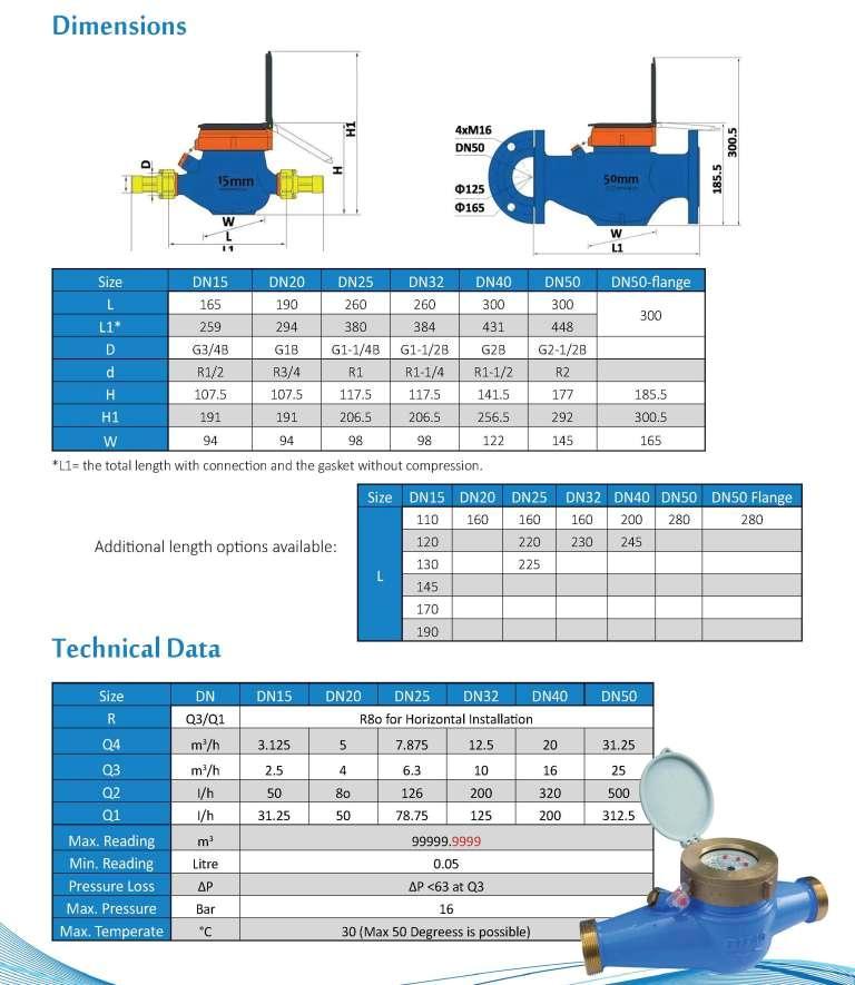
18 20) Water meter Installation Before installing the water meter, make sure that the meter has been chosen correctly. Check that the nominal diameter, flow rate, working temperature and pressure are compatible with actual installation conditions. 1. It is recommended that a straight length of pipe the same diameter as the meter and equivalent in length to 10 times the meter diameter is fitted immediately prior to the meter inlet and 5 times the meter diameter after the meter. 2. Before installing the meter make sure that the two sections of cut pipe are positioned correctly and supported where necessary, clean them carefully (especially if the pipes are empty) and allow water to flow for some time using a section of pipe instead of the meter, to remove any scale/debris leftover from the disturbance to the pipe. 3. Install the meter in a place protected from frost if possible (insulate with lagging materials during the winter months) and locate in the lowest part of the pipe work in order to avoid accumulation of air within the measuring chamber. 4. Install the meter in a position where it can be easily read, but is not accessible for tampering. Locate the meter where it will be safe from disturbance and damage from passing objects. 5. Install the meter so that the water is flowing in the same direction as the arrow shown on the body and in the position recommended by the manufacturer, following any indications on the dial. For guaranteed performance according to ISO 4064, meters should be installed in a perfectly horizontal plain. Accuracy may be reduced if installed in a vertical orientation. 6. It is advisable to install isolation valves upstream and down stream of the meter, in order to make the maintenance or verification of the meter possible. The installation of an internal or external non-return valve is also recommended. 7. There should be no restriction of the pipe at the meter inlet, and flange joints where used, should not obstruct the flow of water into the meter body. Any regulation of the flow should be carried out on the outlet side of the meter. IMPORTANT: Before putting in to operation, it is necessary to purge the pipe and meter of air (for this operation it may be necessary to rotate the meter) Valves must be opened slowly so as not to allow any air present within the pipe work to damage the meter by over running it s internal measuring mechanism. 18
ACCX Air Conditioning
 ACCX Air Conditioning CMR Electrical Ltd Bolton House Five Chimneys Lane Hadlow Down East Sussex TN22 4DX Tel: 01825 733600 Run / Stand-by changeover Controller Installation and operation Manual 1 Two
Manual Simatek Control Unit GFC 32
 Manual Simatek Control Unit GFC 32 Original instructions 1400004_GB Ver. 2014.01.09 Index 1. Main features 3 2. Technical features 3 3. Installation guidelines 4 4. Preliminary checks 5 5. Electrical connections
Manual Control Unit GFC 32
 Manual Control Unit 1400004_EN/05.2017 Index 1. Main features 3 2. Technical features 3 3. Installation guidelines 4 4. Preliminary checks 5 5. Electrical connections 5 6. Settings 6 7. Remote control
Basic User and Installation Manual
 HERON ELECTRIC COMPANY LTD Basic User and Installation Manual Mi-4 Mi-8 Mi-12 Mi-16 Mi-144 Multi -Wire Controller Doc ref. Mi Multi Wire Basic November 2008 TABLE OF CONTENTS 1. About This Controller...
Manual Control Unit GFC 16
 Manual Control Unit 1400003_EN/04.2017 Index 1. Main features 3 2. Tekniske data 3 3. Installation guidelines 4 4. Preliminary checks 5 5. Electrical connections 5 6. Settings 5 7. Remote 7 8. Shut down
INSTRUCTION MANUAL STATION CONTROLLER SC1000 MOTOR PROTECTION ELECTRONICS, INC.
 INSTRUCTION MANUAL STATION CONTROLLER SC1000 MOTOR PROTECTION ELECTRONICS, INC. 2464 Vulcan Road, Apopka, Florida 32703 Phone: (407) 299-3825 Fax: (407) 294-9435 Revision Date: 9-11-08 Applications: Simplex,
Model: TM-1 / TM1-N. 1 Time Clock Series
 Model: TM-1 / TM1-N Model: TM-1 / TM1-N 1 Time Clock Series Table of Contents Product Image Table of Contents Installation Procedure LCD Display Operating Modes Setting the Operating Mode Setting the Clock
Manual Control Unit GFCD 16
 Manual Control Unit 1400002_EN/04.2017 Index 1. Main features 3 2. Technical features 3 3. Installation guidelines 4 4. Preliminary checks 5 5. Electrical connections 5 6. Filter taps 5 7. Settings 6 8.
FCU-4 FAN COIL CONTROLLER
 FCU-4 FAN COIL CONTROLLER BACnet Enabled Description The FCU-4 is designed to provide complete control of fan coil units. The FCU-4 incorporates all the inputs and outputs to ensure that this advanced
FCU-4 FAN COIL CONTROLLER
 FCU-4 FAN COIL CONTROLLER BACnet Enabled Description The FCU-4 is designed to provide complete control of fan coil units. The FCU-4 incorporates all the inputs and outputs to ensure that this advanced
STC7D. Digital Time Clock for TRC500 & TRC800. Installation, Operation, and Maintenance Manual
 STC7D Digital Time Clock for TRC500 & TRC800 Installation, Operation, and Maintenance Manual READ AND SAVE THESE INSTRUCTIONS The purpose of this manual is to aid in the proper installation and operation
Solenoid Valves PN16 for gas flow interception
 s 7 684 INTELLIGAS Solenoid Valves PN16 for gas flow interception E... 2 way solenoid valves, threaded or flanged connections, brass or bronze body. 12V DC or 230V AC coil with manual reset. Normally Open
SS2200 Remote Controller
 SS2200 Remote Controller General Purpose, DC Voltage General The SS2200 Remote Controller is a microprocessor-based programmable controller specifically designed to control single line and dual line centralized
DAS 250L CONTROL COMMUNICATOR INSTALLATION MANUAL
 DAS 250L CONTROL COMMUNICATOR INSTALLATION MANUAL TABLE OF CONTENTS 1. GENERAL DESCRIPTION... P.2 2. STANDARD AND OPTIONAL PARTS LIST..... P.2 3. FEATURE DEFINITIONS... P.3 4. TERMINAL DRAWING AND SPECIAL
CDD Carbon Dioxide Transmitter
 Introduction The OSA CO2 transmitter uses Infrared Technology to monitor CO2 levels within a range of 0 2000 ppm and outputs a linear 4-20 ma or 0-5/0-10 Vdc signal. The enclosure is designed to operate
Model: Available in : Sapphire Black and Glacier White
 Model: Available in : Sapphire Black and Glacier White 1 Table of Contents Product Image 1 Locking/Unlocking the SmartStat 20 Table of Contents 2 Standby/Away Mode 21 What is a Programmable Room Thermostat?
Application program: description and examples
 F a n C o i l U n i t C o n t r o l l e r F a n C o i l 4 9 5 5 1 Application program: description and examples Woertz AG Electrotechnical accessories, installation systems Hofackerstrasse 47, P.O. Box
WDC200 series ELECTRONIC CONTROL for Basins/Baths, Showers and WC s Product Manual
 WDC200 series ELECTRONIC CONTROL for Basins/Baths, Showers and WC s Product Manual Ltd. tel: +44 (0) 1722 744594 Crow Lane, Wilton, fax: +44 (0) 1722 742096 Salisbury, Wiltshire, email: service@wallgate.com
EMP1 OPERATING & INSTALLATION INSTRUCTIONS
 468 Liberty Drive Wittenberg, WI 54499 U.S.A. Tel: 715-253-2801 Ver.11-01-2008 Fax: 715-253-2811 Web: www.solar.imcinstruments.com REV. 5-15-10 EMP1 OPERATING & INSTALLATION INSTRUCTIONS EMP1-0200 PILOT
Installation Manual for D244X Series 24-volt Power Supplies
 Installation Manual for D244X Series 24-volt Power Supplies D2441-B D2441-C D2443-B D2443-C D2445-B D2445-C D2400 Series 1A 24 volts 1A 24 volts 3A 24 volts 3A 24 volts 5A 24 volts 5A 24 volts Dycon Power
ENERGY MANAGER INSTALLATION & USER GUIDE
 ENERGY MANAGER INSTALLATION & USER GUIDE NetThings Ltd 14 New Mart Road Edinburgh EH14 1RL UK E: info@netthings.co.uk T: +44 (0) 131 331 5445 Document 200SM075 Version 2.0 INSTALLATION OVERVIEW 3 INSTALLATION
AMBIFLEX MF626 - USER GUIDE
 AMBIFLEX MF626 - USER GUIDE CONTENTS Page No Product Overview 2 Features 3 Standby Display 4 User Facilities 5 Status Display Mode 6 Measured Temperatures 6 Time Channel Information 7 What is happening
BEP 600-ACSM AC SYSTEMS MONITOR. Installation and Operating Instructions. Page 1
 BEP 600-ACSM AC SYSTEMS MONITOR Installation and Operating Instructions Page 1 This page has been deliberately left blank Page 2 Table of Contents 1. BASICS 4 WARNING AND CAUTION 4 WARNING 4 CAUTION 4
DIGITAL PUMP CONTROLLER. Model Version October 24, 2011
 DIGITAL PUMP CONTROLLER Model 9954-1 Version October 24, 2011 9954-1 Controller Interconnection Diagram PROGRAMMABLE VOLT-FREE CONTACT (10A 240vAC) (FACTORY FITTED OPTION) FOR REMOTE SIGNALLING CONTROL
TOUCHLOCK compact. Master code: Paxton Access Ltd. ins TOUCHLOCK compact kit. Document Contents. Instructions for the following:
 ins-016 160499 TOUCHLOCK compact 100-050 TOUCHLOCK compact kit Instructions for the following: 526-886 TOUCHLOCK compact keypad 100-050 TOUCHLOCK compact kit Master code: Document Contents About this product...2
MAXIMA+ Series Rotary Level Indicator
 MAXIMA+ Series Rotary Level Indicator BinMaster: Division of Garner Industries 7201 N. 98th St., Lincoln, NE 68507 402-434-9102 email: info@binmaster.com www.binmaster.com OPERATING INSTRUCTIONS PLEASE
Touchpad User Guide. National Sales. Product Support. Freecall: Ph:
 Touchpad User Guide National Sales Ph: 1300 306 125 sales@ias.net.au Product Support Freecall: 1800 354 434 support@ias.net.au Designed and Manufactured in Australia by: Innovative Air Systems Pty Ltd.
Manual. NanoTron Dual Timer. Installation Maintenance Repair Manual
 Manual NanoTron Dual Timer Installation Maintenance Repair Manual Advantage Controls P.O. Box 1472 Muskogee, OK 74402 Phone: 800-743-7431 Fax: 888-686-6212 www.advantagecontrols.com email: support@advantagecontrols.com
Instruction Manual Digital socket box timer
 Instruction Manual Digital socket box timer Grässlin UK Vale Rise Tonbridge/Kent TN9 TB Tel. (0 ) 98 88 Fax (0 ) www.tfc-group.co.uk OK page Safety precautions, short description, wiring diagram... Installation...
FP735Si Electronic 3-Channel Full Programmer for Heating and Hot Water with Service Interval Timer. Installation Guide MAKING MODERN LIVING POSSIBLE
 MAKING MODERN LIVING POSSIBLE FP735Si Electronic 3-Channel Full Programmer for Heating and Hot Water with Service Interval Timer Danfoss Heating Installation Guide For a large print version of these instructions
Safety Control Relay Product Catalog
 Product Catalog Wall Mount for use with Safety Mats Safety Edges Safety Bumpers Safety Sensors 2 wire Safety Sensors 4 wire DIN Rail Mount Intrinsically Safe Explosion Proof Wall Mount Introduction The
SOLARIMMERSION IV Advanced Installation Manual v1.9
 SOLARIMMERSION IV Advanced Installation Manual v1.9 1 Contents 1. Overview 2. Technical Specifications 3. Installation Mounting Electrical Installation Clamp Installation Wiring Diagrams 4. Installation
Model: Available in : Sapphire Black and Glacier White
 1 Model: Available in : Sapphire Black and Glacier White 1 Table of Contents Product Image 1 Locking/Unlocking the SmartStat 20 23 Table of Contents 2 Standby/Away Mode Mode 21 24 What is a Programmable
Scanner 2000 Steam Mass Flow Transmitter
 3352051/2 IM-P335-24 MI Issue 2 Scanner 2000 Steam Mass Flow Transmitter Installation and Maintenance Instructions 1. Safety information 2. Mechanical installation 3. Configuring software 4. Wiring procedures
Data Sheet A200 Series Electric Actuators
 Data Sheet Series Electric Actuators Series Electric Actuators Description Trend series actuators are used with Trend VB and SVG valves. Self stroking design minimises commissioning time and improves the
ACTsmart2 Product Range Operating and Installation Instructions
 ACTsmart2 Product Range Operating and Installation Instructions 18-00045 Contents ORDERING INFORMATION......4 INSTALLATION NOTES......5 IMPORTANT......5 PRODUCT SPECIFICATION......5 30 SECOND PROGRAMMING
SERIES CMT CARBON MONOXIDE GAS TRANSMITTER
 SERIES CMT CARBON MONOXIDE GAS TRANSMITTER INSTALLATION OPERATION AND MAINTENANCE MANUAL DWYER INTRUMENTS, INC. PO BOX 373, MICHIGAN CITY, IN. 46360 USA PHONE: 800-872-9141 FAX: 219-872-9057 Web: www.dwyer-inst.com
Manual. NanoTron Dual Timer. Installation Maintenance Repair Manual
 Manual NanoTron Dual Timer Installation Maintenance Repair Manual Advantage Controls P.O. Box 1472 Muskogee, OK 74402 Phone: 800-743-7431 Fax: 888-686-6212 www.advantagecontrols.com email: support@advantagecontrols.com
Actuators for modulating control AME 55, AME 56
 Data sheet Actuators for modulating control AME 55, AME 56 Description Features: Self stroking function Load related Switch off function that prevents overloading Diagnostic LED The actuators are used
ME3 Mobile Cabinet Three Phase Frequency Converter, Operation and Maintenence.
 29-30 Brunel Road, Churchfields Industrial Estate, St. Leonards-on-Sea East Sussex. TN38 9RT. United Kingdom Sales & Service : 01424 853 013 All Other Departments : 01424 853 464 Fax : 01424 852 268 magnuspower.sales@akersolutions.com
GSM AD05 Slave GSM Auto Dialer- Instruction Manual
 GSM AD05 Slave GSM Auto Dialer- Instruction Manual Please read these instructions before you start the installation Features LCD display Programmable 9 x 32 digit phone numbers for each trigger. 10 second
CDD4 Duct Carbon Dioxide Transmitter
 Drill or punch a 1-1/8 or 1-1/4 hole in the duct at the preferred location and insert the probe into the hole to mark the enclosure mounting holes. Remove the unit and drill the four mounting holes. Clean
Easy Flow Indicator Magnetisch-Induktiver Durchflussmesser. Type 8024 For Insertion Fittings. Analog Flow Rate Indicator, 1/2"-16"; P=87 PSI
 Analog Flow Rate Indicator, 1/2"-16"; P=87 PSI Advantages / Benefits Reduced costs of ownership up to 6% Economic integration in pipe systems without any additional piping Shows flow rate with a clear,
TABLE OF CONTENTS INTRODUCTION. 3. Analog Input Analog Output Digital Input Digital Output OPERATIONAL DESCRIPITON.. 7 PROGRAMMING AND INITIAL SETUP.
 DIVERSIFIED HEAT TRANSFER SERIES 700 STEAM GENERATOR CONTROLLER INSTRUCTION MANUAL VISIT OUR WEBSITE AT SIGMACONTROLS.COM SERIES 700 DHT STEAM GENERATOR MANUAL 042514 2 TABLE OF CONTENTS INTRODUCTION.
MAXIMA + Series ROTARY LEVEL CONTROL
 Price $5.00 MAXIMA + Series ROTARY LEVEL CONTROL OPERATING INSTRUCTIONS PLEASE READ CAREFULLY Division of Garner Industries 7201 North 98th Street Lincoln, NE 68507-9741 (402) 434-9102 925-0268 Rev. A
DG2100S Operating Instructions
 DG2100S Operating Instructions STARTUP The DG2100S controller will start automatically when plugged in. The factory settings are: First Stage: When temperature is above 78 o F, water is on 1 minute, off
Nivotec 1. Table of contents. Level monitoring system NT 3500 Technical information / Instruction manual. Page
 Nivotec 1 Table of contents Page Safety notes / Technical support G ------------------------------------------------------------------------------------------------------ Overview G ------------------------------------------------------------------------------------------------------
Ratio Feeder Series J+ Advanced Pumper Controller
 UNPACKING Figure 1 J Plus Controller Please open and inspect your package upon receipt. Your package was packed with great care and all the necessary packing materials to arrive to you undamaged. If you
GSM Communicator GJD710 PLEASE READ THESE INSTRUCTIONS CAREFULLY BEFORE YOU START THE INSTALLATION
 GSM Communicator GJD710 PLEASE READ THESE INSTRUCTIONS CAREFULLY BEFORE YOU START THE INSTALLATION THIS EQUIPMENT WILL NOT WORK ON THE FEATURES NETWORK LCD display showing text in any of 8 different languages
FANCOIL CONTROLLER UNIT TC17B01KNX. Product Handbook
 FANCOIL CONTROLLER UNIT TC17B01KNX Product Handbook Product: TC17B01KNX Description: FANCOIL CONTROLLER UNIT Document Version: 1.2 Date: 09/09/2016 1/37 INDEX 1. General Introduction... 4 2. Product and
Installation, Operation
 Installation, Operation and RENEWAL PARTS IDENTIFICATION 4 (Supersedes PN400-2) MAY, 1986 Type RST and RSTO Unitary Electric Immersion Heaters RST PN400-3 161-049178-001 3 Schedule 40 Steel Pipe Immersed
Model 332 Differential Pressure Transmitter
 Model Differential Pressure Transmitter USERS GUIDE Please read carefully before using. Manufactured by: FURNESS CONTROLS LIMITED Beeching Road, Bexhill, East Sussex, TN9 LJ, England. Telephone (044) 706
PROCESS ANALYSERS. SERVOTOUGH FluegasExact Gas Analyser. QuickStart Manual. Part Number: D Revision: 1 Language: UK English
 PROCESS ANALYSERS SERVOTOUGH FluegasExact Gas Analyser QuickStart Manual Part Number: 02700003D Revision: 1 Language: UK English This page intentionally blank TABLE OF CONTENTS 1. INTRODUCTION............................................
Phoebe LED Spectrum 10W RGB/Tuneable White downlight INSTALLATION AND APP INSTRUCTIONS
 Phoebe LED Spectrum 10W RGB/Tuneable White downlight INSTALLATION AND APP INSTRUCTIONS Contents 1. Product Installation...4 2. Space Requirements & Wiring Diagram...6 3. App Set-up & Adding Lights...7
installation quick guide integrated access control & environmental monitoring
 installation quick guide integrated access control & environmental monitoring Introduction This Installation Quick Guide is suitable for standard wallmountable AX300 controllers. Illustrative technical
Irrigation Control. Quick Start Guide Version 2c. Using Soil Moisture Sensors. Delta-T Devices Ltd
 Irrigation Control Using Soil Moisture Sensors Quick Start Guide Version 2c Delta-T Devices Ltd Overview Irrigation Timer GP1 Solenoid Valve Moisture Content Timer control Sensor control Potential benefits
Wise HP33 THREE PHASE HIGH PRECISION AVR SURVO-MOTOR AUTOMATIC VOLTAGE STABILIZER
 Wise HP33 THREE PHASE HIGH PRECISION AVR SURVO-MOTOR AUTOMATIC VOLTAGE STABILIZER LEN.MAN.STA.111 Rev.4.00/2010 CONTENTS 1. SAFETY INSTRUCTIONS 1 2. INTRODUCTION 2 3. FRONT PANEL AND CONNECTION BOARD 3
MAXIMA + Series ROTARY LEVEL CONTROL
 Price $5.00 MAXIMA + Series ROTARY LEVEL CONTROL OPERATING INSTRUCTIONS PLEASE READ CAREFULLY Division of Garner Industries 7201 North 98th Street Lincoln, NE 68507-9741 (402) 434-9102 925-0268 TABLE OF
7 Day Digital Programmer 2 Channel Surface Mount
 7 Day Digital Programmer 2 Channel Surface Mount Model: TRT036N Installation & Operating Instructions 1. General Information These instructions should be read carefully and retained for further reference
TraceTek Leak Detection Master Module Installation Instructions TOOLS REQUIRED STORAGE
 TTDM-128 TraceTek Leak Detection Master Module Installation Instructions TRACETEK APPROVALS AND CERTIFICATIONS TYPE NM General Signaling Equipment 76LJ GENERAL INFORMATION Please read these instructions
Nokeval. FD100 series. User Manual
 Nokeval FD100 series User Manual Contents Document information... 2 FD100A4 and FD100A6 field displays... 3 Power supply connection... 4 Configuring... 5 Specifications... 7 Document information Device
BlueWave ~ Intelligent Energy Control. Installation and User Manual for BW2/C and BW3/C versions. Quick Guide
 BlueWave ~ Intelligent Energy Control Installation and User Manual for BW2/C and BW3/C versions Quick Guide Press button to override or activate Channel 1 Press button to override or activate Channel 2
Sigma XT Ancillary Board (K588)
") Sigma XT Ancillary Board (K588) Operation and Maintenance Manual Man-1095 Issue 04 October 2009 Index Section Page 1. Introduction... 3 2. Safety and mounting... 3 3. Technical specification... 4 4. Connecting
Sigma XT Ancillary Board (K588) Operation and Maintenance Manual Man-1095 Issue 04 October 2009 Index Section Page 1. Introduction... 3 2. Safety and mounting... 3 3. Technical specification... 4 4. Connecting
Non-communicating room controllers
 3 881 DESIO RXA on-communicating room controllers For fan-coil systems RXA20.1 RXA21.1 RXA22.1 The RXA20.1, RXA21.1 and RXA22.1 room controllers are used for temperature control in individual rooms. For
Model: Touchpad (TFT) Model: TFT
 Model: TFT") Model: Touchpad (TFT) Model: TFT 1 Model: Touchpad TFT Table of Contents Set-Up Product Image Table of Contents Installation Procedure Initial Setup Setting the Clock LCD Display My System Locking the
Model: Touchpad (TFT) Model: TFT 1 Model: Touchpad TFT Table of Contents Set-Up Product Image Table of Contents Installation Procedure Initial Setup Setting the Clock LCD Display My System Locking the
Electronic Dosing Systems Ltd
 Electronic Dosing Systems Ltd Telephone 01299 825 656 Email info@electronicdosingsystems.co.uk Cooling Tower Systems Touch Series Controllers TOUCH series multifunction parameter systems with touch screen
Modulating controlled actuator AME 11
 Data sheet Modulating controlled actuator AME 11 Description In addition to basic function such as manual control and position indication, the actuators are also equipped with force sensitive switch-off
7 Day Digital Programmer 1 Channel Surface Mount
 7 Day Digital Programmer 1 Channel Surface Mount Model: TRT034N Installation & Operating Instructions 1. General Information These instructions should be read carefully and retained for further reference
User Manual. Item no.: Otto Graf GmbH Carl-Zeiss-Str. 2-6 Tel.: +49(0) Kunststofferzeugnisse D Teningen Fax: +49(0)
 Kunststofferzeugnisse D Teningen Fax: +49(0)") User Manual AquaControl + Rainwater System Controller Item no.: 351027 Otto Graf GmbH Carl-Zeiss-Str. 2-6 Tel.: +49(0)7641-5890 Kunststofferzeugnisse D-79 331 Teningen Fax: +49(0)7641-58950 Page 1 Figure
User Manual AquaControl + Rainwater System Controller Item no.: 351027 Otto Graf GmbH Carl-Zeiss-Str. 2-6 Tel.: +49(0)7641-5890 Kunststofferzeugnisse D-79 331 Teningen Fax: +49(0)7641-58950 Page 1 Figure
SONOMETER TM 500 Ultrasonic compact energy meter
 Data sheet SONOMETER TM 500 Ultrasonic compact energy meter Description/Application MID examination certificate No.: DE-13-MI004-PTB011 The SONOMETER 500 is an ultrasonic static compact energy meter designed
MOD. KBC HEAD KONTAX BATCH CONTROLLER
 MOD. KBC HEAD KONTAX BATCH CONTROLLER THE INSTRUMENT DESCRIBED IN THIS MANUAL COMPLIES WITH STANDARDS EMC LIKE ESTABLISHED FROM DIRECTIVE THE EEC AND THE 89/336 DIRECTIVE LOW TENSION THE EEC 73/23 2/2/27
MiG2 CONTROLLERS. 2 & 4 Stage General Purpose Controllers, with Air-conditioning Facilities
 MiG2 CONTROLLERS 2 & 4 Stage General Purpose Controllers, with Air-conditioning Facilities The MiG2 controllers incorporate: 2 Inputs (Configurable as Resistive, 0 10V, 0 20mA or 4 20mA) 2 or 4 Relay Outputs
ASI Systems ML5740A Series
 ML5740A Series Electric Linear Valve Actuators Non-Spring Return APPLICATION The ML5740A series actuators operate standard ASI Systems valves in heating, ventilating and air conditioning (HVAC) applications.
Instruction Sheet Board Style Low Water Cutoff
 Instruction Sheet Board Style Low Water Cutoff 102-305 SUPERSEDES: REVISION E DATED December 12, 2007 #5401173-REV F PLANT ID 001-3902 US Patents 6,904,800, 7,243,540, and 7,317,993 Other Patents Pending
ASI Systems ML5720A Series
 ML5720A Series Electric Linear Valve Actuators Non-Spring Return APPLICATION The ML5720A series actuators operate standard ASI Systems valves in heating, ventilating and air conditioning (HVAC) applications.
Table of Contents. Model: -hw. -hw. Series. Available in : Sapphire Black and Glacier White. Product Image. 16 Table of Contents
 -hw -hw 1 Model: -hw Available in : Sapphire Black and Glacier White Table of Contents Product Image 1 Optional features explained 16 Table of Contents 2 Optional settings features table 16 Installation
DFx Series 1e Controller Instruction Manual
 DFx Series 1e Controller Instruction Manual www.dfxtech.co.uk/cooler 1. Welcome..... 3 2. Series 1e Schematic...3 3. Important Information........ 3 4. Parts List..... 4 5. Specifications..... 5 6. Key
 1373-1-8645 23.09.2014 Operating Instructions Comfort timer control element for blind, light, and relay control 6455-101-500 6455-101-509 1 Safety... 4 2 Intended use... 4 3 Environment... 4 4 Setup and
Badger Meter Europa GmbH. INSTRUCTION MANUAL Deluxe LCD display for the MN series. September Version MN-Deluxe LCD display-09/01-e
 Badger Meter Europa GmbH INSTRUCTION MANUAL Deluxe LCD display for the MN series September 2001 Version MN-Deluxe LCD display-09/01-e Content Content Page 1. To the owner 1 2. Important information 1 3.
BACVIEW MANUAL Software Version 3.06 INSTALLATION AND OPERATION MANUAL
 BACVIEW MANUAL Software Version 3.06 INSTALLATION AND OPERATION MANUAL 641-K31 1 BACVIEW INSTALLATION AND OPERATION IMPORTANT: This manual is for use with controller ZONE I/O 560 FHP part number 641-224
HLS34 Modbus FCU/VAV Controllers installation instructions
 HLS34 Modbus FCU/VAV Controllers installation instructions The HLS34 is specifically designed for individual room temperature and zone control applications. The controllers have built-in RS-485 channel
Installing Keypad and Backplate
 Installing Keypad and Backplate Fig.1 Positioning of Fixing Holes and Cable Outlet Cable Outlet, Drill Diameter 10mm for Cable Access Remove the back plate, which is fitted to rear of the keypad, using
Saturn Mini CT (SS9000/SS9007) Product and Driver Installation Guide. Revision: 3.0 Date: Monday, July 10, 2017 Authors: Gareth Sanders, Alan Chow
 Product and Driver Installation Guide. Revision: 3.0 Date: Monday, July 10, 2017 Authors: Gareth Sanders, Alan Chow") Saturn Mini CT (SS9000/SS9007) Product and Driver Installation Guide Revision: 3.0 Date: Monday, July 10, 2017 Authors: Gareth Sanders, Alan Chow Contents Overview... 3 Section 1: Device Installation...
Saturn Mini CT (SS9000/SS9007) Product and Driver Installation Guide Revision: 3.0 Date: Monday, July 10, 2017 Authors: Gareth Sanders, Alan Chow Contents Overview... 3 Section 1: Device Installation...
DSTHM-2 COMBINED T AND RH DUCT TRANSMITTER. Mounting and operating instructions
 Mounting and operating instructions Table of contents SAFETY AND PRECAUTIONS 3 PRODUCT DESCRIPTION 4 ARTICLE CODES 4 INTENDED AREA OF USE 4 TECHNICAL DATA 4 STANDARDS 4 OPERATIONAL DIAGRAMS 5 WIRING AND
RAIN BIRD RC-4Bi, RC-7Bi, RC-1260Bi SERIES INSTRUCTION MANUAL
 RAIN BIRD RC-4Bi, RC-7Bi, RC-1260Bi SERIES INSTRUCTION MANUAL DESCRIPTION OF CONTROLS Refer to Figure 1 Figure 1 A. HOUR DIAL with 23 CYCLE START PINS The HOUR dial contains 23 pins for rescheduling automatic
High Performance Tension Controller HPTC Electrical Connection Manual
 High Performance Tension Controller HPTC Electrical Connection Manual TTS Systems Limited 14, Highpoint Business Village, Henwood, Ashford, Kent, TN24 8DH Contents Electrical Overview... 3 Power Supply
DESIGO RX Individual room controllers. for fan-coil systems, chilled ceilings and radiators, with LONMARK-compatible bus communications
 3 834 DESIO RX Individual room controllers for fan-coil systems, chilled ceilings and radiators, with MARK-compatible bus communications RXC20.1 RXC21.1 The RXC20.1 and RXC21.1 controllers are used for
Temperature and humidity regulator H3020 H3021 H3023 H3027. Instruction Manual
 Temperature and humidity regulator H3020 H3021 H3023 H3027 Instruction Manual Table of content 1. GENERAL SAFETY RULES... 3 2. GENERAL DESCRIPTION... 4 3. REGULATOR MOUNTING AND CONNECTION... 4 4. DESCRIPTION
LC-5 Level Controller & Flow Monitor
 The Level Controller and Flow Monitor provides a fully integrated Duplex Controller supporting both analog and discrete (float switch) level detection. The unit allows collecting 'rate of flow' information
Touchpad User Guide (Model: C-LCD-122-TL)
") MESSAGE LIBRARY Refer to BBP-5 Instal Guide for information on input triggers. The same message may be linked to more than one trigger. ABBREVIATED VERSION DISPLAYED IN SELECTION SCREEN MESSAGE DISPLAYED
MESSAGE LIBRARY Refer to BBP-5 Instal Guide for information on input triggers. The same message may be linked to more than one trigger. ABBREVIATED VERSION DISPLAYED IN SELECTION SCREEN MESSAGE DISPLAYED
UPGRADE PROGRAM. V70 Series Pumps vs V81T Series Pumps
 VARIAN vacuum technologies UPGRADE PROGRAM V70 Series Pumps vs V81T Series Pumps Technical Memo Technical Memo - 1 - V70 series vs V81-T INDEX Outline drawings ISO63 3 Outline drawings CF2-¾ 4 Outline
CDD4 Series Room CO2 Transmitter Installation Instructions
 CDD4 Series Room CO2 Transmitter Installation Instructions Introduction The CO2 transmitter uses Infrared Technology to monitor CO2 levels and outputs a linear 4-20 ma or 0-5/0-10 Vdc signal. Options include
Model HM-535 Power Supply Installation and Service Instructions
 Model HM-535 Power Supply Installation and Service Instructions 430-535 0104 2004 Heritage MedCall, Inc SENTRY INSTALLATION & SERVICE INSTRUCTIONS POWER SUPPLY UNIT Model HM-535 IMPORTANT SAFETY INSTRUCTIONS
LF1-400 Frequency Converter, Operation and Maintenance
 Vision House, 41 Brunel Road, Churchfields Industrial Estate, St. Leonards-on-Sea East Sussex. TN38 9RT. United Kingdom Sales & Service : 01424 856 172 magnuspower.sales@akersolutions.com magnuspower.service@akersolutions.com
Instruction Manual. M Pump Motor Controller. For file reference, please record the following data:
 Instruction Manual M Pump Motor Controller For file reference, please record the following data: Model No: Serial No: Installation Date: Installation Location: When ordering replacement parts for your
Temperature control unit
 Temperature control unit 5739 18/19 Installation manual Part. U3582A - 12/08-01 PC Contents 1 - Introduction 5 1.1 - Warnings and tips 5 1.2 - Contents of package 5 2 - Description of the Control unit
LC-1 Level Controller & Flow Monitor
 The Level Controller and Flow Monitor provides a fully integrated Duplex Controller. The unit allows collecting 'rate of flow' information and the verification of the run time characteristics of the external
J Do not fit rechargeable batteries. j Keep the Duet II away from. L For use in a dry, indoor. J It is not necessary for you to
 Duet II User manual Duet II User manual Safety information Welcome to geo s energy management service. You ve taken that all important first step towards complete control of your home energy use. Your
DM-918 OPERATIONS MANUAL AUTORANGING MULTIMETER
 DM-918 OPERATIONS MANUAL AUTORANGING MULTIMETER SAFETY INFORMATION The following safety information must be observed to ensure maximum personal safety during the operation of this meter: This meter is
RVL470. Heating controller. G2522en. Installation Instructions. 1 Installation. 2 Commissioning Wall mounting DIN rail mounting
 G2522en Heating controller Installation Instructions RVL470 1 Installation 1.1 Place of installation In a dry room, e.g. the boiler room Mounting choices: In a control panel (on the inner wall or on a