Second Revision No. 1-NFPA [ Global Comment ]
|
|
|
- Nigel Austin
- 6 years ago
- Views:
Transcription
1 Second Revision No. 1-NFPA [ Global Comment ] *************GLOBAL INSTRUCTION - COMP: See Mark's note for clarity*************** Remove all parenthetical terms of (plug/socket) and any variation of (plug and socket outlets)etc. in Sections , (1), (2), 6.4.2(5), , , , , , , , , , , , (4), and A The parenthetical terms to remove are (plug/socket), (plug/socket combination), (plugs)- (socket outlets), (socket-outlets) and (plug and socket outlets) in the body of the document. Delete "Attachment Plug (Plug Cap) (Plug)" and "Receptacle." Additionally, the Committee removes the definition of the term socket and the associated note from Chapter 3, and the annex information in A and A Remove completly A.3.3.9, A Delete "Attachment Plug (Plug Cap) (Plug)" and "Receptacle." Submittal Date: Tue Jan 10 12:46:45 EST 2017 Committee The Committee removes the parenthetical terms (plug/socket), (plug/socket combination), Statement: (plugs)-(socket outlets), (socket-outlets) and (plug and socket outlets) from the body of the document. Additionally the Committee removes the definition of the term socket and the associate note from Chapter 3, the annex information in A and A and the symbols and descriptions related to plug and socket in Figure D.1q. Also Delete "Attachment Plug (Plug Cap) (Plug)" and "Receptacle." These actions are consistent with the actions taken in the 2015 cycle and during the First Draft to remove the parenthetical terms from the body of the document and provide correlation information in Annex J. See the actions taken in SR 1. Public Comment No. 39-NFPA [Section No. A.3.3.9] Public Comment No. 49-NFPA [Section No ] Public Comment No. 52-NFPA [Section No ] Public Comment No. 54-NFPA [Section No. A ] Public Comment No. 59-NFPA [Section No ] Public Comment No. 58-NFPA [Section No ] Public Comment No. 53-NFPA [Section No. A ]
2 Public Comment No. 45-NFPA [Section No ] Public Comment No. 47-NFPA [Section No ] Public Comment No. 48-NFPA [Section No ] Public Comment No. 50-NFPA [Section No ] Public Comment No. 60-NFPA [Section No ] Second Revision No. 59-NFPA [ Global Comment ] The term 'plainly' should be removed before 'visible' throughout the standard. Submitter Full Name: Sonia Barbosa Submittal Date: Fri Mar 17 11:31:55 EDT 2017 Committee When there is a visibility requirement within a section it must be judged based on the particular Statement: application. Using either 'plainly' before 'visible' or 'clearly' before 'visible' does not help with enforcing or interpreting a visibility requirement. Whether something is 'visible' can only be judged on the specific application. Second Revision No. 54-NFPA [ Detail ] ********INSTRUCTION******** This detail is on SR-53 Section to revise Exception No. 1 Exception No.1: An interlock forwithin the control enclosure shall not be required where devices other than the handles of circuit breakers or switches are guarded by a dead-front cover and the use of a key or tool is necessaryrequired for opening the supply circuit disconnecting means enclosure to access exposed live parts. A safety sign shall be provided in accordance with Section 16.2.
3 Submittal Date: Wed Jan 18 15:11:22 EST 2017 Committee The revised text clarifies the required construction of the equipment to use this exception. Statement: This detail is on SR-53 Section to revise Exception No.1. Public Comment No. 31-NFPA [Section No ] Public Comment No. 19-NFPA [Section No ] Second Revision No. 55-NFPA [ Detail ] *************INSTRUCTION********** This detail is to revise the text in Section (3) on SR (3) Be provided with a permanent means permitting it to be locked in the off (open) position only (e.g., by padlocks), independent of the door or cover position. that also prevents When so locked, remote as well as local closing into the ( on ) position shall be prevented. Submittal Date: Wed Jan 18 15:18:58 EST 2017 Committee The Committee restores "when so locked" to more clearly indicate that the preventing of Statement: closing only occurs when locked. This is a ballotable detail on Section (3) for SR-53.
4 Public Comment No. 62-NFPA [Section No ] Second Revision No. 56-NFPA [ Detail ] ***************INSTRUCTION**************** This detail is to revise Section (4) for SR-53 (4) Circuits supplying equipment that arerequiredneed to remain energized for satisfactory operation [e.g., temperature-controlled measuring devices, product (work in progress) heaters, program storage devices, inputs, non-motion outputs, and displays and safety interlocks.] Submittal Date: Wed Jan 18 15:22:22 EST 2017 Committee The TC agreed to add "and safety interlocks" to item "(4)" which are another example of Statement: circuits that may need to remain energized to ensure proper operation of a machine. This ballotable detail is to revise Section (4) for SR-53. Public Comment No. 63-NFPA [Section No ] Second Revision No. 9-NFPA [ Section No ] The provisions of this standard shall apply to the electrical/electronic equipment, apparatus, or systems of industrial machines operatingsupplied from a nominal voltage of 1000 volts or less, and commencing at the point of connection of the supply circuit conductors to the electrical equipment of the machine.
5 Submittal Date: Mon Jan 16 17:23:12 EST 2017 Committee The Technical Committee replaced "operating" with "supplied" which clarifies the voltage Statement: requirement is in regards to the supply voltage not the operating voltage. Public Comment No. 73-NFPA [Section No ] Second Revision No. 57-NFPA [ Section No. 2.4 ] 2.4 References for Extracts in Mandatory Sections. NFPA 70, National Electrical Code, 2017 edition. NFPA 70E, Standard for Electrical Safety in the Workplace, edition. Organization: National Fire Protection Assoc Submittal Date: Wed Jan 25 13:11:13 EST 2017 : Update to the next edition of NFPA 70 E (2018) that will be issued before NFPA 79 is issued. Second Revision No. 14-NFPA [ Section No ] * Basic Protection (Protection From Direct Contact). Protection against electric shock under fault-free conditions.
6 Submittal Date: Tue Jan 17 10:08:56 EST 2017 Committee The TC removes the parenthetical term "Protection From Direct Contact" because this is Statement: explained in the Annex note. The TC gave further consideration to the ballot comments during voting in FR 20. NFPA 70E primarily addresses work practices where NFPA 79 primarily applies to the design and installation of equipment of industrial machinery. There are no similar or equivalent terms in 70E that address this. Public Comment No. 41-NFPA [Section No ] Public Comment No. 7-NFPA [Section No ] Second Revision No. 15-NFPA [ Section No ] * Fault Protection (Protection From Indirect Contact). Protection against electric shock under single-fault conditions. Submittal Date: Tue Jan 17 10:17:08 EST 2017 Committee The TC removes the parenthetical term "Protection from Indirect contact" because this is Statement: explained Annex J. The TC gave consideration to the ballot comments during the voting on FR 20. NFPA 70E primarily addresses work practices where NFPA 79 primarily applies to the design and installation
7 of equipment of industrial machinery. There are no similar or equivalent terms in 70 E that address this. Public Comment No. 8-NFPA [Section No ] Public Comment No. 42-NFPA [Section No ] Second Revision No. 39-NFPA [ New Section after ] Machine Supply Circuit. The conductors between the premises wiring and the machine disconnecting means or terminals. Submittal Date: Wed Jan 18 09:43:03 EST 2017 Committee Add a new definition Machine Supply Circuit. The definition is being added as a companion Statement: comment to comment number 31 and is intended to assist with clarifying what is the supply circuit to the machine. There is a need to differentiate between the requirements for the source(s) of supply for the machine and the downstream disconnects and enclosures. This is not new material based on ballot comments during voting. Public Comment No. 33-NFPA [New Section after ] Second Revision No. 4-NFPA [ Section No ] Visible, Plainly. Able to be seen without the movement or unmounting of surrounding equipment.
8 Submittal Date: Mon Jan 16 16:01:11 EST 2017 Committee The definition was removed as it did not add clarity or usability to the document as not all Statement: possible situations that could occur were considered. When there is a visibility requirement within a section it must be judged based on the particular application. Using either plainly before visible or clearly before visible does not help with enforcing or interpreting a visibility requirement. Whether something is visible can only be judged on the specific application. Public Comment No. 32-NFPA [Section No ] Public Comment No. 13-NFPA [Section No ] Second Revision No. 10-NFPA [ New Section after 4.2 ] 4.3 Installation and Use of Listed or Labeled Equipment. Listed or labeled equipment shall be installed and used in accordance with any instructions included in the listing or labeling. Submittal Date: Mon Jan 16 17:53:06 EST 2017 Committee The TC adds this requirement to clarify that listed or labeled equipment shall be installed and Statement: used in accordance with any instructions included in the listing and labeling. NFPA 79 should not rely on 1.5 to refer users to NEC 110.3(B). This is re-located to Chapter 4 in the new location as a new section after 4.2 as 4.3 as it is more appropriate under the general requirements as opposed to administration in Chapter 1.
9 Public Comment No. 87-NFPA [New Section after 1.6] Second Revision No. 49-NFPA [ Section No ] Circuits Supplied From Power Conversion Equipment. Electrical conductors and equipment supplied by power conversion equipment as part of adjustable speed drive systems and servo drive systems shall be listed flexible motor supply cable marked type RHH, RHW, RHW-2, XHH, XHHW, or XHHW-2 or selected based on the electrical power characteristics involved and the equipment manufacturer s instructions. Submittal Date: Wed Jan 18 12:57:08 EST 2017 Committee Listed flexible motor supply cable marked type RHH, RHW,RHW-2, XHH, XHHW or XHHW-2 will Statement: provide protection against damage which may occur in applications of variable frequency drives subjected to nonlinear power distortions. Use of these cables provides an alternate solution to following the equipment manufacturer s instructions The reference to electrical power characteristics involved is deleted as it is vague and unenforceable (unclear to users of the standard). Deletion of this text addresses Public Comment No. 14, CC Note # 9. Public Comment No. 14-NFPA [Section No ] Public Comment No. 2-NFPA [Section No ] Second Revision No. 13-NFPA [ Section No ] 4.5.2* Electromagnetic Compatibility (EMC). Transient suppression, isolation, or other appropriate means shall be provided where the equipment of an industrial machine generates electrical noise or transients, which can affect the operation of equipment that is on or part of the industrial machine.
10 Submittal Date: Tue Jan 17 09:12:45 EST 2017 Committee The committee statement for FR 14 indicates that: Statement: The effects on other equipment within the surrounding area must be considered but the machine is not required to have noise suppression for other such equipment. The TC has clarified the text and considered the negative comments as directed by the CC. Public Comment No. 15-NFPA [Section No ] Public Comment No. 61-NFPA [Section No ] Public Comment No. 51-NFPA [Section No ] Second Revision No. 50-NFPA [ Section No. 4.8 ] 4.9 Available Fault Current. The available fault current at the point of supply to each industrial control panel of a machinemachine supply circuit disconnecting means shall not be greater than the shortcircuit current rating marked on the machine industrial control panel nameplate. Submittal Date: Wed Jan 18 13:44:09 EST 2017
11 Committee The revised text addressed the concerns of the negative comment during voting as directed Statement: by the CC and is consistent with changes made to address the machine supply circuit. Available fault current is the most consistent term for the amount of current available during a short circuit.. Public Comment No. 16-NFPA [Section No. 4.8] Second Revision No. 40-NFPA [ Chapter 5 [Title Only] ] Supply Circuit Terminations and Disconnecting Means Submittal Date: Wed Jan 18 10:01:44 EST 2017 Committee This revised title indicates that the means for disconnecting power to a machine s supply circuit Statement: conductor terminations and/or other permitted circuit conductors associated with machine equipment are located in this chapter. This simplification will better assist readers of the document which chapter of the standard to refer to for disconnecting means. The TC reconsidered the ballot comments as directed by the CC during revision of the title. Public Comment No. 12-NFPA [Chapter 5 [Title Only]] Public Comment No. 17-NFPA [New Section after 5.1.1] Second Revision No. 53-NFPA [ Sections 5.1, 5.2, 5.3, 5.4, 5.5 ] 5.1 IncomingMachine Supply Circuit Conductor Terminations * Where practicable, the electrical equipment of a machine shall be connected to a single power supply circuit. Where it is necessary to use another supply circuit for certain parts of
12 the equipment (e.g., electronic circuits, electromagnetic clutches), that supply circuit shall, as far as is practicable, be derived from devices (e.g., transformers, converters) forming part of the electrical equipment of the machine The incoming supply circuit conductors shall be terminated at the supply circuit disconnecting means, where practicable. Connections to terminal blocks ahead of the disconnecting means shall be permitted for excepted circuits according to or where the incoming supply circuit conductors are other than those identified for the supply circuit disconnecting means. Terminals for more than one conductor shall be so identified * Where a grounded conductor is used, it shall be clearly indicated in the technical documentation of the machine, such as in the installation diagram and in the circuit diagram. A separate insulated terminal shall be provided for the grounded conductor All terminals for each incoming supply circuit shall be legibly marked and correspond with markings on the technical documentation The wire bending space provided between the terminals of the supply circuit disconnecting means (or terminals described in 5.1.2) and the wall of the enclosure shall not be less than required by Section (B) of NFPA 70. Space shall be determined by the maximum wire size of incomingthe supply circuit conductors or not smaller than the conductors required by Section 670.4(A) of NFPA 70. When the wire bending space is based on more than one conductor per phase, the intended conductor size and number shall be so identified on interconnection diagrams as in Each set of incoming supply circuit conductors on the line side of the disconnecting means shall be separated from all other internal conductors, including conductors of other supply circuits by either of the following: (1) Mounting the supply circuit disconnect as near as practicable to the top of the enclosure with dedicated wire bending space as in (2) Mounting the supply circuit disconnect other than at the top of the enclosure and by separating the supply circuit conductors from other internal conductors by the use of a barrier All live parts on the line side of the supply circuit disconnecting means shall be protected from unintentional direct contact by use of insulation or obstacle(s) when the disconnecting means is in the open (off) position and the enclosure door is open. 5.2* Machine Supply Circuit Grounding Terminal. A grounding terminal shall be provided for each incoming supply circuit. 5.3 Machine Supply Circuit Disconnecting (Isolating) Means General. The following general requirements in through apply to through A supply circuit disconnecting means shall be provided for the following:
13 (1) Each supply circuit connecting to a machine (2) Each supply circuit connecting to a feeder system using collector wires, collector bars, slip-ring assemblies, or flexible cable systems (reeled, festooned) to a machine or a number of machines (3) Each on-board power source (e.g., generators, uninterruptible power supplies) Exception: Communication, remote control, and signaling circuits of less than 50 volts shall not be required to be provided with a supply circuit disconnecting means * Each supply circuit disconnecting means required by shall be legibly marked to indicate the equipment it disconnects A mainsupply circuit disconnecting means shall be marked as main if multiple Machine Supply Circuit Disconnect if additional disconnecting means are supplied from the mainsupply circuit disconnecting means Where a machine is supplied by more than one supply circuit, a marking shall be installed at each supply circuit disconnect location denoting the location of all other supply circuit disconnects The supply circuit disconnecting means shall disconnect (isolate) the electrical equipment of the machine, including all control circuits, from the supply circuit when required (e.g., for work on the machine, including the electrical equipment). Circuits that are not required to be disconnected by the supply circuit disconnecting means shall comply with Each supply circuit disconnecting means other than attachment plugs and receptacles shall be mounted within the control enclosure or immediately adjacent thereto. Exception No. 1: Externally mounted supply circuit disconnecting means, whether interlocked or not interlocked with the control enclosure, supplying machines totaling 2 hp or less shall be permitted to be mounted up to 6 m (20 ft) away from the control enclosure, provided the control enclosure is marked to indicate the location of the supply circuit disconnecting means and the supply circuit disconnecting means complies with all the following: (1) Is in sight of the control enclosure it supplies (2) Is readily accessible (3) Is marked in accordance with Exception No. 2: A supply circuit disconnecting means mounted in a separate enclosure and interlocked in accordance with with the control enclosure(s) it supplies shall be permitted to be mounted up to 6 m (20 ft) away from the control enclosure, provided the control enclosure is marked to indicate the location of the supply circuit disconnecting means and the supply circuit disconnecting means complies with all the following: (1) Is in sight of the control enclosure it supplies (2) Is readily accessible
14 (3) Is marked in accordance with Each supply circuit disconnecting means mounted within or adjacent to the control enclosure shall be interlocked with the control enclosure in accordance with Detail SR-54 Exception No. 1: An interlock withinfor the control enclosure shall not be required where devices other than the handles of circuit breakers or switches are guarded by a deadfront cover and the use of a key or tool is requirednecessary for opening the supply circuit disconnecting means enclosure to access exposed live parts. A safety sign shall be provided in accordance with Section Exception No. 2: Where a supply circuit disconnecting means supplying machines totaling 2 hp or less is not located within or adjacent to the control enclosure it supplies, the control enclosure shall comply with or Where a supply disconnecting means is an attachment plug and receptacle, the control enclosure it supplies shall comply with Where compliance with is required, a safety sign shall be provided in accordance with Section Where two or more supply circuit disconnecting means are provided within the control enclosure for multiple supply circuits, they shall be grouped in one location where practicable. Protective interlocks for their correct operation shall be provided where a hazardous condition or damage to the machine or to the work in progress can occur Type. The supply circuit disconnecting device shall be one of the following types: (1) A listed motor circuit switch (switch disconnector) rated in horsepower (2) A listed molded case circuit breaker (3) A listed molded case switch (4) An instantaneous trip circuit breaker that is part of a listed combination motor controller limited to single motor applications (5) A listed self-protected combination controller limited to single motor applications (6) An attachment plug and receptacle (plug/socket combination) for cord connection Requirements * Where the supply circuit disconnecting device is one of the types in 5.3.2(1) through 5.3.2(5), the device shall fulfill all of the following requirements: Detail SR-55 (1) Isolate the electrical equipment from the supply circuit and have one off (open) and one on (closed) position only. Circuit breakers, instantaneous trip circuit breakers, molded-case switches, and self-protected combination motor controllers are permitted to have a reset (tripped) position between off (open) and on (closed). (2) Have an external operating means (e.g., handle) that complies with
15 * Exception: Power-operated switchgear need not be operable from outside the enclosure where there are other means to open it. (3) Be provided with a permanent means permitting it to be locked in the off (open) position only (e.g., by padlocks), independent of the door or cover position, that also prevents. When so locked, remote as well as local closing into the (on)on position shall be prevented. (4) Simultaneously disconnect all ungrounded conductors of the power supply circuit. (5) Be operable by qualified persons independent of the door or cover position without the use of accessory tools or devices. (6) Be rated for the application as follows: (a) With an ampere rating at least 115 percent of the sum of the full-load currents required for all equipment that is in operation at the same time under normal conditions of use (b) Where rated in horsepower, with a horsepower rating at least equal to that which is defined by Table (B) of NFPA 70 for a locked rotor current equal to the largest sum resulting from the locked rotor currents of any combination of motors that can be started simultaneously and the full-load currents of the remaining motor and non-motor loads that can be operated at that time (c) With a voltage rating at least equal to the nominal supply circuit voltage (7) Be of a type that plainly indicates whether it is in the off (open) or on (closed) position. When the supply circuit disconnecting device is an attachment plug and receptacle (plug/socket combination), it shall fulfill all of the following requirements: Global SR-1 (1) Have a load-break rating or be interlocked with a switching device that is load-break rated and complies with (6) (2) Be listed as a switch-rated plug and receptacle (plug/socket combination) rated greater than 20 amperes or 2 hp (3) Be of such a type and be so installed as to prevent unintended contact with live parts at any time, even during insertion or removal of the connectors (4) Have a first-make, last-break electrical grounding contact (5) Have a retaining means to prevent unintended or accidental disconnection where rated at more than 20 amperes (6) Be located within sight from the operator station and be readily accessible
16 In addition to the requirements in , an additional switching device on the machine shall be provided for routine power switching operations of the machine on and off Operating Handle The center of the grip of the operating handle of the supply circuit disconnecting means, when in its highest position, shall be not more than 2.0 m (6 ft 7 in.) above the servicing level. A permanent operating platform, readily accessible by means of a permanent stair or ladder, shall be considered the servicing level for the purpose of this requirement An operating handle of the supply circuit disconnecting means required by shall meet the following criteria: (1) Be readily accessible with doors in the open or closed position (2) Maintain the environmental rating of the enclosure to the degree necessary for the application when installed through the control enclosure (3) Not be restricted by the enclosure door when the door is in the open position Excepted Circuits Detail SR-56 The following circuits shall not be required to be disconnected by the mainmachine supply circuit disconnecting means: (1) Lighting circuits for lighting needed during maintenance or repair (2) Attachment plugs and receptacles (plug and socket outlets) for the exclusive connection of repair or maintenance tools and equipment (e.g., hand drills, test equipment) (3) Undervoltage protection circuits that are only used for automatic tripping in the event of supply circuit failure (4) Circuits supplying equipment that are requiredneed to remain energized for satisfactory operation [e.g., temperature-controlled measuring devices, product (work in progress) heaters, program storage devices, inputs, nonmotion outputs, and displays, and safety interlocks] The supplyexcepted circuits for excepted circuits shall be provided with all of the following: (1) A disconnecting means, isolating transformer, and overcurrent protection mounted in an enclosure adjacent to the main control enclosure or within the control enclosure, adjacent to the main supply circuit disconnecting means (2) Line side (of the supply circuit disconnect) supply circuit conductors, when internal to the control enclosure, that are separate from and do not share a raceway with other conductors and that are encased in rigid or flexible conduit if longer than 460 mm (18 in.) The control interlocking circuits shall be capable of being disconnected at the control panel from which they are sourced.
17 Where the excepted circuits are not disconnected by the supply circuit disconnecting means, all of the following requirements shall be met: (1) Permanent safety sign(s) shall be placed adjacent to the supply circuit disconnecting operating handle(s), indicating that it does not de-energize all exposed live parts when it is in the open (off) (isolated) position as in (2) A statement containing the information from shall be included in the machine documentation. (3) A permanent safety sign shall be placed on a nonremovable part inside the control enclosure in proximity to each excepted circuit, or shall be identified by color as defined in Means for Removal of Power for Prevention of Unexpected Start-Up Means for removal of power shall be provided when prevention of unexpected start-up is required (e.g., during maintenance where the unexpected start-up of a machine or part of the machine results in a hazardous situation). Such means shall be as follows: (1) Appropriate for the intended use, and (2) Conveniently located, and (3) Readily identifiable as to their function and purpose, and (4) Provided with permanent means for locking in the off position only Removal of power shall be accomplished by the use of one of the following: 5.4.3* (1) The machine supply circuit disconnecting means (2) Additional devices conforming to or (3) Other means (e.g., a contactor switched off by a control circuit) that meet the requirements of and Where other means of removal of power are used, a single failure of any of its components shall not result in an inadvertent or unexpected start-up Other means of removal of power shall be employed only for situations that include the following: (1) Routine exchange of work pieces, fixtures, and tools requiring no significant dismantling of the machine (2) Work on the electrical equipment where all of the following conditions exist: (a) There is no hazard arising from electric shock and burn. (b) The switching off means cannot be negated by the work. (c) The work is of a minor nature (e.g., replacement of plugin devices without disturbing existing wiring).
18 (d) There is no hazard arising from the unexpected energizing or de-energizing of circuits. 5.5 Devices for Disconnecting (Isolating) Electrical Equipment Devices shall be provided for disconnecting (isolating) electrical equipment to enable work to be performed when it is de-energized and isolated The machine supply circuit disconnecting devicemeans(see Section 5.3) shall be permitted to fulfill this requirement where there is no need for disconnecting individual portions of the electrical circuit Where it is expected that it will be necessary to work on separately operable parts of a machine, a disconnecting means shall be permitted for the electrical equipment of each such part of the machine requiring separate disconnection The following devices shall be permitted to fulfill the isolating function of 5.5.3: (1) Devices described in (2) A manual motor controller marked suitable as motor disconnect and in compliance with UL 508, Standard for Industrial Control Equipment, where located on the load side of the last short-circuit protective device (in the branch) (3) System isolation equipment that incorporates control lockout stations and is listed for disconnection purposes where located on the load side of the main supply circuit disconnecting means and overcurrent protection Each operating means of the isolation devices in shall be as follows: (1) Readily accessible and complies with Exception: Switches and circuit breakers installed adjacent to motors, appliances, or other equipment that they supply shall be permitted to be accessible by portable means. (2) Within sight of the part of the machine requiring disconnection (3) Readily identifiable as an isolating means and marked to identify the equipment that is disconnected (4) For other than attachment plugs, provided with permanent means for locking in the off position only
19 Submittal Date: Wed Jan 18 14:55:40 EST 2017 Committee The concept to replace the term incoming with machine clarifies the machine s supply circuit Statement: is the one that originates from the premises wiring. Adding the word machine before the words supply circuit clarifies to the users of the document which requirements apply to circuits supplying the machine and which requirements apply to other permitted circuits originating from the machine (load side of the machine supply circuit disconnecting means). Other changes were made as necessary so the requirements read correctly and align with the new definition of a "Machine Supply Circuit." In "show markup" The parenthetical term "plug/socket", and the term "plainly" were also deleted to be consistent with their deletion in other sections. Section (6) (a), (b), and (c) were incorrectly renumbered and underlined and must be restored. Section (2) (a), (b), (c) and (d) were incorrectly renumbered and underlined and must be restored. Revise Exception No. 1 to Section as a separate ballotable detail SR-54 Revise text to Section (3) as a separate ballotable detail SR-55 Revise Section (4) as a separate ballotable detail SR-56 Public Comment No. 30-NFPA [Section No ] Public Comment No. 56-NFPA [Section No ] Public Comment No. 46-NFPA [Section No ] Public Comment No. 44-NFPA [Section No ] Public Comment No. 18-NFPA [Section No [Excluding any Sub-Sections]] Second Revision No. 17-NFPA [ Section No ] * Each motor controller and its associated wiring shall be protected as an individual branch circuit by a short-circuit protective device (SCPD) as specified by the controller manufacturer. The maximum rating of the designated SCPD shall be as shown in Table Exception No. 1: Table shall not apply to Design B energy efficient motor circuits. The provisions of NFPA 70 shall be observed for Design B energy efficient motor circuits.
20 Exception No. 2: Where the controller is an adjustable speed drive that is listed and marked Suitable for Output Conductor Protection, the maximum rating of the designated SCPD shall be permitted to be determined by replacing the full-load current in Table with the drive s rated input current. The SCPD shall not exceed the rating marked on the adjustable speed drive or in the manufacturer s instructions. Table Maximum Rating or Setting of Fuse and Circuit Breakers: Motor, Motor Branch Circuit, and Motor Controller Full-Load Current (%) Fuse Class with Non Time Delay AC-2 AC-3 AC-4 R CF or J CC T Type of Application 2 a Fuse Class with Time Delay 1b AC-2 AC-3 AC-4 RK-5 3c RK CF or J CC Instantaneous trip circuit breaker 4d Inverse trip circuit breaker 5e Note: Where the values determined by this table do not correspond to the standard sizes or ratings, the next higher standard size, rating, or possible setting shall be permitted. 2a Types of starting duty are as follows: (a)(1) AC-2: All light-starting duty motors, including slip-ring motors; starting, switching off (b)(2) AC-3: All medium starting duty motors including squirrel-cage motors; starting, switching off while running, occasional inching, jogging, or plugging but not to exceed 5 operations per minute or 10 operations per 10 minutes and all wye-delta and two-step autotransformer starting motors (c)(3) AC-4: All heavy starting duty motors including squirrel-cage motors; starting, plugging, inching, jogging 1b Where the rating of a time-delay fuse (other than CC type) specified by the table is not sufficient for the starting of the motor, it shall be permitted to be increased but shall in no case be permitted to exceed 225 percent. The rating of a time-delay Class CC fuse and non time-delay Class CC, J, CF, or T fuse shall be permitted to be increased but shall in no case exceed 400 percent of the full-load current. 2 Types of starting duty are as follows: (a) AC-2: All light-starting duty motors, including slip-ring motors; starting, switching off (b) AC-3: All medium starting duty motors including squirrel-cage motors; starting, switching off while running, occasional inching, jogging, or plugging but not to exceed 5 operations per minute or 10 operations per 10 minutes and all wye-delta and two-step autotransformer starting motors (c) AC-4: All heavy starting duty motors including squirrel-cage motors; starting, plugging, inching, jogging 3c Unless a motor controller is listed for use with RK-5 fuses, Class RK-5 fuses shall be used only with NEMA-rated motor controllers.
21 4d Instantaneous trip circuit breakers shall be permitted to be used only if they comply with all of the following: (a)(1) They are adjustable. (b)(2) Part of the combination controller has motor-running protection, short-circuit protection, and ground-fault protection in each conductor. (c)(3) The combination is especially identified for use. (d)(4) It is installed per any instructions included in its listing or labeling. (e)(5) They are limited to single motor applications; circuit breakers with adjustable trip settings are to be set at the controller manufacturer's recommendation, but not greater than 1300 percent of the motor full-load current. 5e Where the rating of an inverse time circuit breaker specified in this table is not sufficient for the starting current of the motor, it shall be permitted to be increased but in no case exceed 400 percent for full-load currents of 100 amperes or less or 300 percent for fullload currents greater than 100 amperes A listed self-protected combination controller shall be permitted in lieu of the devices specified in Table for branch circuit and overload protection of a single motor circuit Where a listed self-protected combination controller has an adjustable, instantaneous trip setting, the setting shall not exceed 1300 percent of full-load motor current for other than Design B energy efficient motors and not more than 1700 percent of full-load motor current for Design B energy efficient motors. Submittal Date: Tue Jan 17 11:09:47 EST 2017 Committee The text has been revised to clarify that the exception is permitted to be used but not Statement: required. The TC has considered the comments as directed by the CC and determined that no additional revisions are required. Public Comment No. 21-NFPA [Section No ]
22 Second Revision No. 20-NFPA [ Section No ] Several motors, each not exceeding 1 hp in rating, shall be permitted on a nominal 120- volt branch circuit protected at not over 20 amperes or a 600-volt 1000-volt nominal or less branch circuit, protected at not over 15 amperes, where all of the following conditions are met: (1) The full-load rating of each motor does not exceed 6 amperes. (2) The rating of the branch-circuit short-circuit and ground-fault protective device marked on any of the controllers is not exceeded. The short-circuit and ground-fault protection is provided by a single inverse time circuit breaker or single set of fuses. (3) Individual overload protection conforms to Section 7.3. Submittal Date: Tue Jan 17 11:23:53 EST 2017 Committee This comment is an output of the 1000V NFPA79 Task Group. The revised change aligns Statement: with (A) in the 2017 NEC. Public Comment No. 74-NFPA [Section No ] Second Revision No. 16-NFPA [ Section No ] Two or more motors, or one or more motor(s) and other load(s), and their control equipment shall be permitted to be connected to a single branch circuit where short-circuit and ground-fault protection is provided by a single inverse time circuit breaker or a single set of fuses, provided the following conditions under (1) and either (2) or (3) are met: (1) Each motor controller and overload device is either listed for group installation with specified maximum branch-circuit protection or selected such that the ampere rating of the motor branch short-circuit and groundfault protective device does not exceed that permitted by for that individual motor controller or overload device and corresponding motor load.
23 .. (2) The rating or setting of the branch short-circuit and ground-fault protection device does not exceed the values in Table for the smallest conductor in the circuit. Exception: Where a controller is an adjustable speed drive that is listed and marked Suitable for Output Conductor Protection, the conductors from the drive to the motor shall not applybe required to be used when determining the smallest conductor in the circuit. The conductors from the drive to the motor shall have an ampacity in accordance with Sections 12.5 and (3) The rating or setting of the branch short-circuit and ground-fault protection does not exceed the value specified in for the highest rated motor connected to the branch circuit plus an amount equal to the sum of the fullload current ratings of all other motors and the ratings of other loads connected to the circuit. Where this calculation results in a rating less than the ampacity of the branch circuit conductors, it shall be permitted to increase the maximum rating of the fuses or circuit breaker to a value not exceeding that permitted by Sections 12.5 and Overcurrent protection for loads other than motor loads shall be in accordance with 7.2.3, 7.2.4, and Where 16 AWG or 18 AWG conductors are used for branch circuit conductors or tap conductors under , the rating and type of the branch short-circuit and ground-fault protection shall be in accordance with Table Relationship Between Conductor Size and Maximum Rating or Setting of Short-Circuit Protective Device for Power Circuits Group Installations Conductor Size. (AWG) Maximum Rating. Fuse or Inverse Time* Circuit Breaker (amperes) 18 See footnote. 16 See footnote / / /0 800 *Maximum ratings and type of branch short-circuit and ground-fault protective devices for 16 AWG and 18 AWG shall be determined in accordance with
24 Submittal Date: Tue Jan 17 10:59:52 EST 2017 Committee The Technical Committee has revised the text in exception No. 2 for clarity for application of a Statement: single branch circuit supplying two or more motors, or one or more motor(s) and other load(s), and their control equipment. Public Comment No. 22-NFPA [Section No ] Second Revision No. 18-NFPA [ Section No ] For group installations described in (3), the conductors of any tap supplying a single motor shall not be required to have an individual branch-circuit short-circuit and ground-fault protective device, provided they comply with one of the following: (1) No conductor to the motor shall have an ampacity less than that of the branch-circuit conductors. (2) No conductor to the motor shall have an ampacity less than one-third that of the branch-circuit conductors, with a minimum in accordance with Sections 12.5 and 12.6, the conductors to the motor overload device being not more than 7.5 m (25 ft) long and being suitably protected from physical damage in accordance with Chapter 13. (3) Conductors from the point of the tap from the branch-circuit short-circuit and ground-fault protective device to a listed manual motor controller additionally marked Suitable for Tap Conductor Protection in Group Installations or to a branch circuit protective device shall be permitted to have an ampacity not less than 1/10 the rating or setting of the branch-circuit short-circuit and ground-fault protective device. The conductors from the controller to the motor shall have an ampacity in accordance with Sections 12.5 and The conductors from the branch-circuit short-circuit and ground-fault protective devicepoint of the tap to the controller shall (1) be enclosed either by an enclosed controller or by a raceway and be not more than 3 m (10 ft) long or (2) have an ampacity not less than that of the branch-circuit conductors.
25 Submittal Date: Tue Jan 17 11:15:46 EST 2017 : The TC has revised the text to correlate with (D)(3) of NFPA Public Comment No. 64-NFPA [Section No ] Second Revision No. 41-NFPA [ Section No ] Restarting. Upon restoration of the voltage or upon switching on the incomingmachine supply circuit, automatic or unintentional restarting of the machine shall be prevented when such a restart causes a hazardous condition. Submittal Date: Wed Jan 18 12:04:36 EST 2017 Committee Revising the text so it reads machine supply circuit clarifies the machine s supply circuit Statement: originates from the premises wiring. This clarification will assist readers of the document with determining which requirements apply to the circuit supplying the machine and which requirements apply to circuits originating from the machine (load side of the machine supply circuit disconnecting means).
26 Second Revision No. 58-NFPA [ Section No ] Surge ProtectionProtective Devices (SPDs). SPDs shall be permitted to be provided for industrial machinery with safety interlock circuits to protect against the effects of overvoltages due to lightning or switching surges. Organization: National Fire Protection Assoc Submittal Date: Wed Jan 25 13:24:41 EST 2017 Committee The technical committee revised the existing requirement in to require an appropriate SPD Statement: for protection of industrial machinery with safety interlock circuits to correlate with NFPA The manufacturer of the industrial machinery can determine what specific type of SPD is to be used to provide the needed protection based on the installation and equipment design. Second Revision No. 21-NFPA [ Section No. 7.9 ] 7.9 Power Factor Correction Capacitor Overcurrent Protection. Where capacitors are installed for motor power factor correction on circuits of volts, nominal, and under, overcurrent protection for the conductors shall be provided. Each capacitor cell or capacitor bank shall be protected against rupture of the individual cells. Protection included as a part of the capacitor assembly shall be permitted. Submittal Date: Tue Jan 17 11:25:32 EST 2017
27 Committee The proposed change increases the voltage to 1000V to include all equipment covered by Statement: the revised scope change. Public Comment No. 75-NFPA [Section No. 7.9] Second Revision No. 38-NFPA [ Section No ] Connections. Except at either the source or first disconnecting means of a grounded separately derived system, grounded conductors shall not be connected to the equipment grounding conductor. Submittal Date: Tue Jan 17 18:11:29 EST 2017 Committee The first use of the term grounded is unnecessary since an ungrounded separately derived Statement: system does not contain a grounded conductor. This change improves clarity. The TC reviewed the CC comments as directed by the CC. Public Comment No. 84-NFPA [Section No ] Public Comment No. 23-NFPA [Section No ] Second Revision No. 23-NFPA [ Section No ] Effective Ground FaultGround-Fault Current Path. All parts of thethe effective ground faultground-fault current path shall be capable of withstanding the highest thermal and mechanical stress that can be caused by fault currents in that part of the circuitsafely carrying the maximum ground-fault current likely to be imposed on it from any point where a ground fault could occur from the point of connection of the supply circuit conductors to the electrical equipment of the machine.
28 Submittal Date: Tue Jan 17 12:41:43 EST 2017 Committee The language accepted in the FR could be misunderstood. The proposed language is Statement: consistent with the same requirement in of NFPA 70. Public Comment No. 83-NFPA [Section No ] Second Revision No. 24-NFPA [ Section No ] Where electrical devices are mounted on metal mounting panels that are located within nonmetallic enclosures, the metal mounting panels shall be effectively grounded. Where electrical devices are mounted on metal mounting panels that are located within nonmetallic enclosures, the metal mounting panels shall be connected to an equipment grounding conductor or bonding jumper. Submittal Date: Tue Jan 17 14:26:42 EST 2017 Committee This is an editorial change to address an inadvertent addition of a duplicate sentence Statement: during the transition to TerraView. Public Comment No. 80-NFPA [Section No ]
29 Second Revision No. 25-NFPA [ Section No ] For each machine supply circuit, an equipment grounding conductor terminal shall be provided in the vicinity of the associated phase conductor terminals and shall be connected to the equipment grounding conductor. Submittal Date: Tue Jan 17 14:28:50 EST 2017 Committee Shall be is added to improve readability of the text. And "machine" is added Revising the text Statement: so it reads machine supply circuit clarifies the machine s supply circuit originates from the premises wiring. This clarification will assist readers of the document with determining which requirements apply to the circuit supplying the machine and which requirements apply to circuits originating from the machine (load side of the machine supply circuit disconnecting means). Public Comment No. 81-NFPA [Section No ] Second Revision No. 26-NFPA [ Section No ] Where an auxiliary grounding electrode is specified, theby the industrial machinery manufacturer or provider, a terminal shall accommodate this additional grounding electrode conductor. Submittal Date: Tue Jan 17 14:34:46 EST 2017
30 Committee For other than custom built industrial machinery, the industrial machinery manufacturer has no Statement: way of knowing if the installer or user will specify something. This will clarify that the additional terminal requirement is only necessary to be provided by the industrial machinery manufacturer if they specify an auxiliary grounding electrode. Public Comment No. 82-NFPA [Section No ] Second Revision No. 27-NFPA [ Section No ] Removing a device shallequipment grounding conductors and bonding jumpers shall be installed in a manner such that removal of a wiring device, such as a receptacle or switch, does not interrupt the continuity of the equipment grounding conductor or bonding jumperconductor. Submittal Date: Tue Jan 17 14:53:04 EST 2017 Committee Pressure connectors and terminal bars are devices and removing them would interrupt the Statement: continuity of the equipment grounding conductor. The intent of the requirement is to ensure that devices that are likely to be replaced, can be removed and replaced without losing the effective ground fault path. The sentence is restructured to improve readability. Public Comment No. 78-NFPA [Section No ] Second Revision No. 28-NFPA [ Section No ] Raceways, wireways, and cable trays shall not be used as equipment grounding or bonding conductors.equipment containing energized conductors shall be provided with a separate wire-type equipment grounding conductor or bonding jumper.
31 Submittal Date: Tue Jan 17 14:59:35 EST 2017 Committee The structure of the language is revised to avoid leaving other types of equipment, such as an Statement: auxiliary gutters, from the list and instead provides the intended requirement in positive text. Public Comment No. 79-NFPA [Section No ] Second Revision No. 30-NFPA [ Section No ] The source of supply for all control circuits shall be taken from the load side of the supply disconnecting means. Exception: The power supply circuit to controlcontrol circuits meeting the requirements of excepted circuits in (4)shall be permitted to be taken from the line side of the supply disconnecting means or other power source. Submittal Date: Tue Jan 17 15:50:49 EST 2017 : The TC removes the phrase "The power supply circuit to" from the exception for clarity.
32 Public Comment No. 25-NFPA [Section No ] Second Revision No. 31-NFPA [ Section No ] Stop by De-Energization. Except for cycle stop commands (stop by energization), stop functions shall be initiated by de-energization, not energization of a device or as a command to a programmable logic controller (PLC). Submittal Date: Tue Jan 17 16:09:19 EST 2017 Committee The new requirement has been deleted because it is unclear as to the extent of stop commands Statement: it covers and in its reference to the use of Safety PLC's for issuing of stop commands. Stopping by de-energization is presently mentioned in Annex H.2 as one component for minimizing the probability of control function failure. Public Comment No. 65-NFPA [Section No ] Second Revision No. 42-NFPA [ Section No ] Emergency switching off shall be accomplished by disconnecting the incomingmachine supply circuit of the machine effecting a Category 0 stop. Where the machine cannot tolerate the Category 0 stop, it shall be necessary to provide other protection (e.g., against direct contact), so that emergency switching off is not necessary.
33 Submittal Date: Wed Jan 18 12:13:32 EST 2017 Committee Revising the text so it reads machine supply circuit clarifies the machine s supply circuit Statement: originates from the premises wiring. This clarification will assist readers of the document with determining which requirements apply to the circuit supplying the machine and which requirements apply to circuits originating from the machine (load side of the machine supply circuit disconnecting means). Second Revision No. 32-NFPA [ Section No ] Busbars shall be securely fastened in place and the. The minimum spacing between uninsulated parts of busbars, busbar terminals, and other bare metal parts for busbars in feeder circuits shall not be less than specified in Table (D) of NFPA 70. Submittal Date: Tue Jan 17 16:29:00 EST 2017 Committee The requirement has been revised to indicate the increased spacing is only required for Statement: busbars located in feeder circuits. Public Comment No. 66-NFPA [Section No ] Second Revision No. 33-NFPA [ Section No ]
34 When this is not practicable, itit shall be permissible to place a pocket that is suitable for the environment outside the door of the control enclosure or compartment in a wellidentified location. Submittal Date: Tue Jan 17 16:54:23 EST 2017 Committee Statement: The TC removes "When it is practicable" to allow the print pocket to be located elsewhere. Someone should not need to open an enclosure, possibly exposing themselves to hazards. Public Comment No. 89-NFPA [Section No ] Second Revision No. 34-NFPA [ Section No [Excluding any Sub-Sections] ] Access and working space for control cabinets and compartments operating at volts, nominal, or less to ground and likely to require examination, adjustment, servicing, or maintenance while energized shall comply with the provisions of Chapter 11. Sufficient access and working space shall be provided and maintained around all control cabinets and compartments to permit ready and safe operation and maintenance of such control cabinets and compartments. Working space for cabinets and compartments that contain supply conductors to industrial machinery that are covered by Article 670 of NFPA 70 shall be in accordance with the NEC. Submittal Date: Tue Jan 17 17:06:43 EST 2017
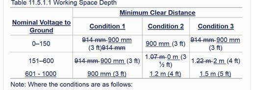
35 Committee The TC changed the requirement to increase the voltage to 1000V to include all equipment Statement: covered by the revised scope change and aligns with the 2017 edition of NFPA 70. Public Comment No. 76-NFPA [Section No [Excluding any Sub-Sections]] Second Revision No. 35-NFPA [ Section No ] The depth of the working space in the direction of access to live parts shall not be less than indicated in Table Distances shall be measured from the control cabinet or compartment front or opening. Table Working Space Depth Minimum Clear Distance Nominal Voltage to Ground Condition 1 Condition 2 Condition mm (3 ft) mm (3 ft) mm (3 ft) mm (3 ft) m (31 2 ft) m (4 ft) mm (3 ft) 1.2 m (4 ft) 1.5 m (5 ft) Note: Where the conditions are as follows: Condition 1 Exposed live parts on one side and no live or grounded parts on the other side of the working space, or exposed live parts on both sides effectively guarded by insulating materials. Insulated wire or insulated busbars operating at not over 300 volts to ground shall not be considered live parts. Condition 2 Exposed live parts on one side and a grounded surface on the other side. Concrete, brick, or tile walls shall be considered as grounded. Condition 3 Exposed live parts on both sides of the working space (not guarded as provided in Condition 1) with the operator between. Exception No. 1: Working space shall not be required in back or sides of control cabinets or compartments, where there are no renewable or adjustable parts on the back or sides and where all connections are accessible from locations other than the back or sides. Where rear access is required to work on de-energized parts on the back of enclosed control cabinet and compartment, a minimum working space of 762 mm (2 1 2 ft) horizontally shall be provided. Exception No. 2: By special permission, working space clearance depth of 762 mm (2 1 2 ft) or less shall be permitted where all uninsulated parts are at a voltage no greater than 50 volts rms ac or 60 volts dc. Exception No. 3: Condition 2 working clearance depth shall be permitted between control cabinets or compartments located across the aisle from each other or across from nonmachinery-associated switchgear, panelboards, or motor control centers where conditions of maintenance and supervision ensure that written procedures have been adopted to prohibit the affected equipment doors on both sides of the aisle from being open at the same time and qualified persons who are authorized will service the installation.
36
37 Exception No. 4: Condition 1 working clearance depth shall be permitted between control cabinets or compartments located across the aisle from each other, or across from a grounded surface, where all associated control cabinet or compartment devices and equipment operating at greater than 50 volts rms ac or 60 volts dc are separately enclosed, guarded, or constructed so that openings to live parts of the devices and equipment will not permit the entry of a 12.5 mm (0.5 in.) diameter rod. Exception No. 5: By special permission, the minimum working space clearance depth of 762 mm (2 1 2 ft) shall be permitted where all of the following conditions are met: (1) The control cabinet or compartment is operating at not over 150 volts lineto-line or line-to-ground. (2) The conditions of maintenance and supervision ensure that only qualified persons will service the installation. (3) The control cabinet and compartment require a tool to open. (4) Where only diagnostic troubleshooting and testing on live parts are involved. (5) The door(s) of the control cabinet and compartment open at least 90 degrees or are removable. Supplemental Information File Name Description Approved _screen_shot_table.jpg table updated Submittal Date: Tue Jan 17 17:12:59 EST 2017 Committee This comment is an output of the 1000V NFPA 79 Task Group. The proposed change increases Statement: the voltage to 1000V to include all equipment covered by the revised scope change and aligns with the 2017 NEC changes to Table (A)(1). One issue the task group identified to be addressed is if the working distances apply to the incoming source voltage or to any working voltage present in the panel including DC voltages. Public Comment No. 77-NFPA [Section No ]
38 Second Revision No. 19-NFPA [ Section No ] Conductors supplying a single motor or multiple motors shall be permitted to be sized based on 125 percent of the highest rated motor at demand factors based on the loading or application of the motors. Submittal Date: Tue Jan 17 11:20:08 EST 2017 Committee Statement: The TC has considered the negative comments expressed during voting as directed by the CC and deleted the requirement as it can result in smaller unprotected conductors. Public Comment No. 67-NFPA [Section No ] Public Comment No. 27-NFPA [New Section after ] Second Revision No. 48-NFPA [ Section No ] * The color GREEN with or without one or more YELLOW stripes shall be used to identify the equipment grounding conductor where insulated or covered. This color identification shall be strictly reserved for the equipment grounding conductor. GREEN shall be the predominant color when used in combination with one or more YELLOW stripes. Exception No. 1: Conductors with green insulation or insulation that is green with one or more yellow stripes shall be permitted to be used for other than equipment grounding purposes where all of the following conditions are met: (1) The conductor is part of a multiconductor cable. (2) The multiconductor cable containing the conductor contains only circuits supplied from a source limited to less than 50 volts. (3) The multiconductor cable containing the conductor contains only circuits supplied from a source limited to no more than a power-limited Class 2 energy level.
39 (4) The conductor is reidentified at all accessible locations, or the multiconductor cable is part of a listed assembly. Exception No. 2: It shall be permitted to use conductors of any color, provided the insulation or cover is appropriately identified at all points of access. Exception No. 3: For grounded control circuits, use of a GREEN insulated conductor with or without one or more YELLOW stripes or a bare conductor from the transformer terminal to a grounding terminal on the control panel shall be permitted. Submittal Date: Wed Jan 18 12:47:15 EST 2017 Committee This action reinstates and revises Exception 1 that was removed in the First Revision Meeting. Statement: The revision addresses the concerns that low-energy equipment supplied from an ungrounded source should not place a restriction on the use of the green conductor in a multiconductor cable. The changes correlate with the language in Section of NFPA 70 as directed by the CC. The changes provide necessary restrictions on use of green conductors to address the substantiation for removing the exception in FR 39. Public Comment No. 28-NFPA [Section No ] Public Comment No. 90-NFPA [New Section after ] Public Comment No. 68-NFPA [Section No ] Second Revision No. 5-NFPA [ Section No ] 14.8 Direction Arrow. Where reverse rotation produces an unsafe condition or causes damage to connected equipment, a direction arrow shall be installed. The arrow shall be adjacent to the motor and plainly visible.
40 Submittal Date: Mon Jan 16 16:33:01 EST 2017 Committee Using the term plainly before visible does not help with enforcing or interpreting a visibility Statement: requirement nor does it add any clarity to the requirement. Whether something is visible can only be judged based on the specific application. Public Comment No. 34-NFPA [Section No. 14.8] Second Revision No. 36-NFPA [ New Section after 14.9 ] Motor Controllers. Motor controllers shall be provided in accordance with Article 430, Part VII, of NFPA 70. Submittal Date: Tue Jan 17 17:38:39 EST 2017 Committee Presently, specific guidance on selecting motor controllers is missing in NFPA 79. Motor overload Statement: protection is specified to be provided using Article 430 of NFPA 70, Part III in NFPA Transformer protection is required to be provided using NEC Article 450, Part IV in NFPA Motor controllers should have a similar more specific reference other than NFPA which sends you back to NFPA 70. Public Comment No. 55-NFPA [New Section after 14.9] Second Revision No. 11-NFPA [ Sections , ]
41 Safety signs shall be plainly visible on the enclosure door or cover * Electrical equipment for industrial machines, such as industrial control panels and the enclosures of disconnecting devices, shall be marked with a safety sign in accordance with ANSI Z535.4, Product Safety Signs and Labels, to warn qualified persons of potential electric shock and arc flash hazards The marking shall be located so as to be plainly visible to qualified persons before examination, adjustment, servicing, or maintenance of the equipment It shall be permitted to omit safety signs where the size of the enclosure precludes placement of the label on the enclosure (e.g., operator machine interfaces, control stations, position sensors). Submittal Date: Mon Jan 16 18:28:39 EST 2017 Committee Using the term plainly before visible does not help with enforcing or interpreting a visibility Statement: requirement nor does it add any clarity to the requirement. Whether something is visible can only be judged based on the specific application. Public Comment No. 36-NFPA [Section No ] Public Comment No. 35-NFPA [Section No ] Second Revision No. 12-NFPA [ Section No ] Control equipment shall be legibly and durably marked in a way that is plainly visible after the equipment is installed. A nameplate giving the following information shall be attached to the outside of the enclosure, or on the machine immediately adjacent to the enclosure: (1) Name or trademark of supplier (2) Model, serial number, or other designation
42 (3) *Rated voltage, number of phases and frequency (if ac), and full-load current for each supply (4) Ampere rating of the largest motor or load (5) Maximum ampere rating of the short-circuit and ground-fault protective device, where provided (6) Short-circuit current rating of the industrial control panel (7) Electrical diagram number(s) or the number of the index to the electrical drawings Submittal Date: Mon Jan 16 18:35:27 EST 2017 Committee Using the term plainly before visible does not help with enforcing or interpreting a visibility Statement: requirement nor does it add any clarity to the requirement. Whether something is visible can only be judged based on the specific application. Public Comment No. 37-NFPA [Section No ] Second Revision No. 37-NFPA [ Section No ] The full-load current shown on the nameplate shall not be less than the full-load currents for all motors and other equipment that can be in operation at the same time under normal conditions of use, design load, and duty cycle. Where unusual loads or duty cycles require oversized conductors, the required capacity shall be included in the full-load current specified on the nameplate.
43 Submittal Date: Tue Jan 17 18:04:38 EST 2017 Committee The proposed text addresses the concerns expressed in PI 113 without always requiring Statement: measurement of input current. Public Comment No. 72-NFPA [Section No ] Second Revision No. 43-NFPA [ Section No ] Where more than one incomingmachine supply circuit is to be provided, the nameplate shall state the information in for each circuit. Submittal Date: Wed Jan 18 12:14:51 EST 2017 Committee Revising the text so it reads machine supply circuit clarifies the machine s supply circuit Statement: originates from the premises wiring. This clarification will assist readers of the document with determining which requirements apply to the circuit supplying the machine and which requirements apply to circuits originating from the machine (load side of the machine supply circuit disconnecting means). Second Revision No. 7-NFPA [ Section No ] Where only a single motor or motor controller is used, the motor nameplate shall be permitted to serve as the electrical equipment nameplate where it is plainly visible.
44 Submittal Date: Mon Jan 16 17:05:40 EST 2017 Committee Using the term plainly before visible does not help with enforcing or interpreting a visibility Statement: requirement nor does it add any clarity to the requirement. Whether something is visible can only be judged based on the specific application. Public Comment No. 38-NFPA [Section No ] Second Revision No. 29-NFPA [ Sections 18, 18 ] Chapter 18 Testing and Verification 18.1* General. The verification of the continuity of the equipment grounding circuiteffective ground-fault current path shall be conducted and documented. When the electrical equipment is modified, the requirements in Section 18.7 shall apply. Applicable tests shall be performed where deemed necessary in accordance with the references in the following list: (1) Verification that the electrical equipment is in compliance with the technical documentation (see Chapter 17) (2) Insulation resistance test (see Section 18.3) (3) Voltage test (see Section 18.4) (4) Protection against residual voltages test (see Section 18.5) (5) Functional test (see Section 18.6) 18.2* Continuity of the Equipment Grounding CircuitEffective Ground-Fault Current Path. One of the following methods shall be used to verify the continuity of the equipment grounding circuiteffective ground-fault current path: (1) UseUsing an impedance measuring device, take into account any impedance in the measuring circuit. The measured impedance shall be 0.1 ohm or less. (2) Apply a current of at least 10 amperes, 50 Hz or 60 Hz, derived from aan SELV source. The tests are to be made between the equipment grounding terminal and relevant points that are part of the equipment grounding
45 . circuiteffective ground-fault current path; the measured voltage between the equipment grounding terminal and the points of test is not to exceed the values given in Table Table 18.2 Verification of Continuity of the Equipment Grounding CircuitEffective Ground- Fault Current Path Minimum Equipment Grounding Conductor Cross-Sectional Area of the Branch Under Test. (AWG) *Values are given for a test current of 10 amperes Insulation Resistance Tests. Maximum Measured. Voltage Drop* (V) >8 1.0 The insulation resistance measured at 500 volts dc between the power circuit conductors and the equipment grounding circuiteffective ground-fault current path shall not be less than 1 megohm. The test shall be permitted to be made on individual sections of the machine. 18.4* Voltage Tests. The machine shall withstand without breakdown a test voltage gradually applied from 0 volts to 1500 volts ac or 2121 volts dc and held at the maximum value for a period of at least 1 second between the conductors of all primary circuits and the equipment grounding circuiteffective ground-fault current path. The test voltage shall be supplied from an isolated power supply with a minimum rating of 500 volt amperes. Components that are not rated to withstand the test voltage shall be disconnected during testing Protection Against Residual Voltages. Residual voltage tests shall be performed to ensure compliance with Section Functional Tests. The functions of electrical equipment, particularly those related to safety and safeguarding, shall be tested Retesting. Where a portion of the machine and its associated equipment is changed or modified, that portion shall be reverified and retested as appropriate.
46 The linked image cannot be displayed. The file may have been moved, renamed, or deleted. Verify that the link points to the correct file and location. Submittal Date: Tue Jan 17 15:20:20 EST 2017 Committee Statement: The changes in terms made in Chapter 8 during the first revision meeting with FR 29, placed the terminology in Chapter 18 in conflict. These changes make the document consistent. Public Comment No. 85-NFPA [Sections 18, 18] Second Revision No. 44-NFPA [ Section No ] 19.4 Contactor. Where a contactor is installed ahead of the incoming supply conductors to the servo drive, the contactor current rating shall not be less than 115 percent of the maximum servo drive nameplate rating or shall be sized in accordance with the manufacturer's specifications. Submittal Date: Wed Jan 18 12:16:03 EST 2017 : The TC removed the term "incoming" to be consistent with other sections. Second Revision No. 45-NFPA [ Section No. A ] A For large complex machinery comprising a number of widely spaced machines working together in a coordinated manner, more than one incomingmachine supply circuit might be needed, depending upon the site supply circuit arrangements (see 5.3.1).
47 The linked image cannot be displayed. The file may have been moved, renamed, or deleted. Verify that the link points to the correct file and location. Submittal Date: Wed Jan 18 12:22:31 EST 2017 Committee Revising the text so it reads machine supply circuit clarifies the machine s supply circuit Statement: originates from the premises wiring. This clarification will assist readers of the document with determining which requirements apply to the circuit supplying the machine and which requirements apply to circuits originating from the machine (load side of the machine supply circuit disconnecting means). Second Revision No. 46-NFPA [ Section No. A.11.5 ] A.11.5 Figure A.11.5 identifies the requirements for determining the working spaces for electrical equipment associated with industrial machinery. Figure A.11.5 Clarification of Working Space Requirements at the Termination Location of IncomingMachine Supply Circuit Conductors.

48 The left side of Figure A.11.5 depicts a situation where the incomingmachine supply circuit disconnecting means, required by , is located in the industrial machine control panel or compartment. The right side of Figure A.11.5 depicts a situation where the incomingmachine supply circuit disconnecting means, required by , is externally mounted to the industrial machine control cabinet or the compartment it supplies. Submittal Date: Wed Jan 18 12:23:44 EST 2017 Committee Revising the text so it reads machine supply circuit clarifies the machine s supply circuit Statement: originates from the premises wiring. This clarification will assist readers of the document with determining which requirements apply to the circuit supplying the machine and which requirements apply to circuits originating from the machine (load side of the machine supply circuit disconnecting means).
49 Second Revision No. 47-NFPA [ Section No. B.1 ] B.1 It is recommended that the information in Figure B.1 be provided by the intended user of the equipment. It facilitates an agreement between the user and supplier on basic conditions and additional user requirements to ensure proper design, application, and utilization of the electrical equipment of the machine (see Section 4.1). Figure B.1 Inquiry Form for the Electrical Equipment of Machines.
50 DELETED
51
52
53 Submittal Date: Wed Jan 18 12:29:32 EST 2017 Committee Revising the text so it reads machine supply circuit clarifies the machine s supply circuit Statement: originates from the premises wiring. This clarification will assist readers of the document with determining which requirements apply to the circuit supplying the machine and which requirements apply to circuits originating from the machine (load side of the machine supply circuit disconnecting means). Second Revision No. 51-NFPA [ Section No. D.1 ] D.1 Figure D.1(a) through Figure D.1(q) are not intended to be (design) guidelines. They are included only to illustrate documentation methods. Figure D.1(a) Cover Sheet and Sheet Index.
54 Figure D.1(b) System Layout and Installation Diagram. DELETED
55 Figure D.1(c) Block (System) Diagram. Figure D.1(d) Interconnection Diagram.
56 Figure D.1(e) Elementary Schematic. Figure D.1(f) PLC Input Diagram.
57
58 Figure D.1(g) PLC Output Diagram.
59
60 Figure D.1(h) Sample Enclosure Layout Interior.
61 Figure D.1(i) Sample Enclosure Layout Exterior. Figure D.1(j) Sequence of Operations Graphical.
 Sequence of Operations")
62 Figure D.1(k) Sequence of Operations Descriptive Graphical.
63 Figure D.1(l) Sample Servo Diagram.
64 Figure D.1(m) Sample PLC Network Station Layout.
65
66 Figure D.1(n) Sample Operator Station.
67
 ISO (A2) Drawing Standard Framework.")
68 Figure D.1(o) Sample Parts List. Figure D.1(p) ISO (A2) Drawing Standard Framework.
 Page 1 of 149 First Revision No. 50-NFPA 79-2012 [ Global Input ] Delete the parenthetical terms used to describe IEC terms that follow terms used in NFPA 79 such as "protective bonding". Add information
Page 1 of 176. Public Input No. 140-NFPA [ Global Input ] Statement of Problem and Substantiation for Public Input
![Page 1 of 176. Public Input No. 140-NFPA [ Global Input ] Statement of Problem and Substantiation for Public Input](/thumbs/90/101376721.jpg "Page 1 of 176. Public Input No. 140-NFPA [ Global Input ] Statement of Problem and Substantiation for Public Input") of 164 4/22/2016 1:06 PM Public Input No. 140-NFPA 79-2016 [ Global Input ] Type your content here...globably change "cableless" to "wireless" 9.2.5.1.2 9.2.7 9.2.7.1 9.2.7.2 9.2.7.3.1 9.2.7.3.1(2) 9.2.7.3.1(4)
of 164 4/22/2016 1:06 PM Public Input No. 140-NFPA 79-2016 [ Global Input ] Type your content here...globably change "cableless" to "wireless" 9.2.5.1.2 9.2.7 9.2.7.1 9.2.7.2 9.2.7.3.1 9.2.7.3.1(2) 9.2.7.3.1(4)
SECTION DISCONNECT SWITCHES
 SECTION 16440 DISCONNECT SWITCHES PART 1 - GENERAL 1.01 RELATED DOCUMENTS A. Drawings and general provisions of the Contract, including General and Supplementary Conditions and other Division 01 Specification
Understanding SCCR. THE BEST ELECTRICAL CONTROLS BUSINESS ON THE PLANET! Unmatched Service Superior Product Quality Advantage Pricing
 Understanding SCCR What is SCCR? When it comes to industrial machinery, it s critical to ensure that electrical panels are designed and built with the proper SCCR to maintain the system, eliminate downtime
SECTION ENCLOSED SWITCHES AND CIRCUIT BREAKERS
 SECTION 262816 - ENCLOSED SWITCHES AND CIRCUIT BREAKERS PART 1 - GENERAL 1.1 RELATED DOCUMENTS A. Drawings and general provisions of the Contract, including General and Supplementary Conditions and Division
Spring Test 13 due 06/14/2013
 Spring Test 13 due 06/14/2013 Multiple Choice Identify the choice that best completes the statement or answers the question. 1. The power supply to the mobile home shall be a feeder assembly consisting
Application Techniques CENTERLINE 2100 Motor Control Centers
 POWER SYSTEM CONSIDERATIONS FOR PRODUCT SELECTION Application Techniques CENTERLINE 2100 Motor Control Centers Power System Considerations for Product Selection i Power System Considerations for Product
DANGER DANGER: is used in this manual to warn of high voltages capable of causing shock, burns, or death.
 Installation/Operation Manual TABLE OF CONTENTS Page UNPACKING AND INSTALLATION Unpacking and Preliminary Inspection...2, 3 Model Number...9 LOCATION CONSIDERATIONS Environment, Equipment Performance,
Bulletin Installation of solar photovoltaic systems Rules , , , , and
 Bulletin 64-5-0 Installation of solar photovoltaic systems Rules 64-060, 64-200, 64-214, 84-020, 84-024 and 84-030 Scope (1) Introduction (2) Disconnecting means (a) Disconnecting means for solar photovoltaic
Standards Update Notice (SUN) Issued: April 25, 2017
 Issued: April 25, 2017") Standard Information Standard Number: UL 1951 Standard Name: Electric Plumbing Accessories Standard Edition and Issue Date: 2 nd Edition Dated July 22, 2011 Date of Revision: February 21, 2017 Date of
Standard Information Standard Number: UL 1951 Standard Name: Electric Plumbing Accessories Standard Edition and Issue Date: 2 nd Edition Dated July 22, 2011 Date of Revision: February 21, 2017 Date of
National Fire Protection Association. 1 Batterymarch Park, Quincy, MA Phone: Fax:
 National Fire Protection Association 1 Batterymarch Park, Quincy, MA 02169-7471 Phone: 617-770-3000 Fax: 617-770-0700 www.nfpa.org M E M O R A N D U M TO: Members of the NEC-Code Making Panel 11 FROM:
Spring Test 5 due 4/26/2013
 Spring Test 5 due 4/26/2013 Multiple Choice Identify the choice that best completes the statement or answers the question. 1. Where fixed multioutlet assemblies are employed, each feet or fraction thereof
SECTION (16410) - ENCLOSED SWITCHES AND CIRCUIT BREAKERS
 - ENCLOSED SWITCHES AND CIRCUIT BREAKERS") SECTION 26 28 16 (16410) - ENCLOSED SWITCHES AND CIRCUIT BREAKERS PART 1 GENERAL 1.01 SUMMARY A. Section Includes: 1. Individually Mounted Switches and Circuit Breakers Used for the following: a. Service
SECTION 26 28 16 (16410) - ENCLOSED SWITCHES AND CIRCUIT BREAKERS PART 1 GENERAL 1.01 SUMMARY A. Section Includes: 1. Individually Mounted Switches and Circuit Breakers Used for the following: a. Service
SECTION PANELBOARDS
 SECTION 16450 PART 1 - GENERAL 1.01 DESCRIPTION A. Section includes requirements for panelboards providing fault interrupting capability and overcurrent protective devices. 1.02 REFERENCE STANDARDS A.
1510 MOTOR CONTROLLERS
 SECTION 262913- MOTOR CONTROLLERS PART 1 - GENERAL 1.1 RELATED DOCUMENTS A. Drawings and general provisions of contract, including general and supplementary conditions and Division 1 specification section,
(1986; Rev. 1989) Molded Case Circuit Breakers and Molded Case Switches. (1985; Rev. 1988) Enclosures for Electrical Equipment (1000 Volts Maximum)
 Molded Case Circuit Breakers and Molded Case Switches. (1985; Rev. 1988) Enclosures for Electrical Equipment (1000 Volts Maximum)") Section 16306 50/60-HERTZ (HZ) SOLID STATE FREQUENCY CONVERTER Index PART 1 GENERAL PART 2 PRODUCTS 1.1 References 2.1 Frequency Converters 1.2 Factory Tests 2.2 Conduit and Fittings 1.3 Submittals 2.3
Section 16306 50/60-HERTZ (HZ) SOLID STATE FREQUENCY CONVERTER Index PART 1 GENERAL PART 2 PRODUCTS 1.1 References 2.1 Frequency Converters 1.2 Factory Tests 2.2 Conduit and Fittings 1.3 Submittals 2.3
Standards Update Notice (SUN) Issued: January 11, 2016
 Issued: January 11, 2016") Standard Information Standard Number: UL 962A Standard Name: Furniture Power Distribution Units Standard Edition and Issue Date: 3 rd Edition Dated September 29, 2014 Date of Revision: September 8, 2015
Standard Information Standard Number: UL 962A Standard Name: Furniture Power Distribution Units Standard Edition and Issue Date: 3 rd Edition Dated September 29, 2014 Date of Revision: September 8, 2015
Standards Update Notice (SUN) Issued: July 28, 2017
 Issued: July 28, 2017") Standard Information Standard Number: CSA C22.2 No. 107.1 Standard Name: Power conversion equipment Standard Edition and Issue Date: 4 th Edition Dated June 2016 Date of Issue: June 2016 Date of Previous
Standard Information Standard Number: CSA C22.2 No. 107.1 Standard Name: Power conversion equipment Standard Edition and Issue Date: 4 th Edition Dated June 2016 Date of Issue: June 2016 Date of Previous
SECTION 16450: NON-AUTOMATIC TRANSFER SWITCH / QUICK CONNECT GENERATOR SWITCHBOARD <S> <OM>
 SECTION 16450: NON-AUTOMATIC TRANSFER SWITCH / QUICK CONNECT GENERATOR SWITCHBOARD PART 1 - GENERAL 1.1 RELATED DOCUMENTS A. Drawings and general provisions of the Contract, including General
FORM FOR PROPOSAL FOR 2014 NATIONAL ELECTRICAL CODE
 FORM FOR PROPOSAL FOR 2014 NATIONAL ELECTRICAL CODE INSTRUCTIONS PLEASE READ CAREFULLY Type or print legibly in black ink. Use a separate copy for each proposal. Limit each proposal to a SINGLE section.
Meter Enclosure and Equipment Standards
 Meter Enclosure and Equipment Standards (a) (b) General Requirements: CITY OF OCALA UTILITY SERVICES METER ENCLOSURE AND EQUIPMENT STANDARDS: (1) To avoid the costs associated with having to replace unacceptable
1. Coordination of series-rated devices is permitted where indicated on Drawings.
 SECTION 16055 - OVERCURRENT PROTECTIVE DEVICE COORDINATION PART 1 - GENERAL 1.1 RELATED DOCUMENTS A. Drawings and general provisions of the Contract, including General and Supplementary Conditions and
Applying branch circuit breakers and supplementary protectors in North America
 Product Application AP01102005E WMZT WMZS Applying branch circuit breakers and supplementary protectors in North America Introduction Eaton offers two types of miniature circuit breakers for use in North
Document C0. Use for:
 Date: July 27, 2015 Document C0 Use for: Connection of Electric Generation that will operate with an Open Transition (Category 1) between the Ameren System and the Generator or operate with a Synchronized
Electrical Integration of PV Systems. Ridha Hamidi, Ph.D.
 Electrical Integration of PV Systems Ridha Hamidi, Ph.D. 1 Many articles in the NEC are applicable to the electrical integration of a PV system, particularly Article 690. 2 The NEC defines the various
R-LB R-LX Series Installation, Operation & Maintenance Manual
 Installation, Operation & Maintenance Manual WARNINGS Safety First Hazardous Voltage & Shock Hazard Only qualified licensed electricians should install or service SPDs Hazardous voltages exist within SPDs
Great Western Painting Assured Equipment Grounding Conductor Program OR Ground Fault Circuit Interrupter (GFCI)
") Assured Equipment Grounding Conductor Program OR Ground Fault Circuit Interrupter (GFCI) GROUND FAULT CIRCUIT INTERRUPTERS Wiring design and protection. - 1926.404 Our company uses ground fault circuit
Assured Equipment Grounding Conductor Program OR Ground Fault Circuit Interrupter (GFCI) GROUND FAULT CIRCUIT INTERRUPTERS Wiring design and protection. - 1926.404 Our company uses ground fault circuit
Installation Manual. APEX Series. Silicon and MOV Panel Protection. APEX Series
 Installation Manual APEX Series Silicon and MOV Panel Protection APEX Series APEX Series Installation Guide 2 Table of Contents Mechanical Installation 3 Table One - Application Rating 3 Figure 1 - Mounting
Liebert AccuVar (ACV Series) Surge Protective Device (SPD) (With Noise Filtering) GUIDE SPECIFICATIONS for a Parallel Surge Suppression System
 Surge Protective Device (SPD) (With Noise Filtering) GUIDE SPECIFICATIONS for a Parallel Surge Suppression System") Liebert AccuVar (ACV Series) Surge Protective Device (SPD) (With Noise Filtering) GUIDE SPECIFICATIONS for a Parallel Surge Suppression System Part 1 General 1.01 Summary A. These specifications describe
Liebert AccuVar (ACV Series) Surge Protective Device (SPD) (With Noise Filtering) GUIDE SPECIFICATIONS for a Parallel Surge Suppression System Part 1 General 1.01 Summary A. These specifications describe
IEC H.P. Rated Pin and Sleeve Sequential contacts engagement during mating and un-mating IEC configurations specific to each voltage and
 IEC 60309 H.P. Rated Pin and Sleeve Sequential contacts engagement during mating and un-mating IEC configurations specific to each voltage and amperage to prevent interchangeability of voltages Watertight
Solar Combiner Enclosure
 Installation Instructions Solar Combiner Enclosure Catalog Numbers 1000-SB006, 1000-SB012 Topic Page Description 1 Important Safety Instructions 3 Nameplate Data 4 Planning for Installation 4 Install the
Applying branch circuit breakers and supplementary protectors in North America
 Supersedes June 2017 FAZ-NA-L FAZ-NA FAZ Applying branch circuit breakers and supplementary protectors in North America Introduction Eaton offers three types of miniature circuit breakers for use in North
Spring Test 17 due 06/14/2013
 Spring Test 17 due 06/14/2013 Multiple Choice Identify the choice that best completes the statement or answers the question. 1. The NEC defines cable as a cylindrical assembly composed of a conductor centered
HUBBELL SPIKESHIELD Wired-In Branch Panels Surge Protective Device (SPD)
") HUBBELL SPIKESHIELD Wired-In Branch Panels Surge Protective Device (SPD) Instruction Bulletin 8222-0513B Retain for future use. SPIKESHIELD Wired-In Branch Panels 8222-0513B 05/2012 Table of Contents Precautions...
HUBBELL SPIKESHIELD Wired-In Branch Panels Surge Protective Device (SPD) Instruction Bulletin 8222-0513B Retain for future use. SPIKESHIELD Wired-In Branch Panels 8222-0513B 05/2012 Table of Contents Precautions...
Designing with Thermally Protected TCMOV Varistors for Type 1 and Type 2 UL1449 3rd Edition Applications
 TCMOV Varistors for Type 1 and Type What is UL 1449? Underwriters Laboratories standard UL 1449 has become the primary safety standard for surge protective devices (SPDs). It describes the materials and
Standards Update Notice (SUN) Issued: August 11, 2017
 Issued: August 11, 2017") Standard Information Standard Number: UL 621 Standard Name: Ice Cream Makers Standard Edition and Issue Date: 7 th Edition Dated May 7, 2010 Date of Revision: February 15, 2017 Date of Previous Revision
Standard Information Standard Number: UL 621 Standard Name: Ice Cream Makers Standard Edition and Issue Date: 7 th Edition Dated May 7, 2010 Date of Revision: February 15, 2017 Date of Previous Revision
NEC 2008 Code Changes Top 20 Revisions. By: Rafi Wartan, PE, LEED AP
 NEC 2008 Code Changes Top 20 Revisions By: Rafi Wartan, PE, LEED AP #1 Article 210.4 MULTIWIRE BRANCH CIRCUITS The rule on simultaneous disconnecting means requirements for multiwire branch circuits was
GE Digital Energy. Power Quality
 GE Digital Energy Power Quality INSTALLATION, OPERATION AND MAINTENANCE MANUAL GE TRANQUELL Enhanced Thermal Protection (ETP) Series Wall Mounted Medium and High Exposure Surge Protective Devices (SPDs)
Electrical Components and Equipment for General Use Self Inspection Checklist
 Name of School: Optional Information Date of Inspection: Vocational Program/Course/Room: Signature of Inspector: Electrical Components and Equipment for General Use Self Inspection Checklist Guidelines:
AIR COOLED MODULAR RECTIFIER
 CONTROLLED POWER COMPANY SPECIFICATIONS AIR COOLED MODULAR RECTIFIER Spc1800a1 5JAN1999 SPECIFICATION S-1800-A MODULAR (REMOVABLE AND NON-REMOVABLE MODULES) AIR COOLED RECTIFIER Standard output power range:
SECTION VARIABLE FREQUENCY MOTOR CONTROLLERS (VFD)
") SECTION 26 29 23 VARIABLE FREQUENCY MOTOR CONTROLLERS (VFD) PART 1 -GENERAL 1.1 SYSTEM DESCRIPTION A. Definitions: The Variable Speed AC Motor Drive (hereafter referred to as "VFD") shall be designed to
SECTION 26 29 23 VARIABLE FREQUENCY MOTOR CONTROLLERS (VFD) PART 1 -GENERAL 1.1 SYSTEM DESCRIPTION A. Definitions: The Variable Speed AC Motor Drive (hereafter referred to as "VFD") shall be designed to
Introduction to the Inspection Checklist for Rooftop Solar Photovoltaic (PV) Systems in Goshen, IN
 Systems in Goshen, IN") Introduction to the Inspection Checklist for Rooftop Solar Photovoltaic (PV) Systems in Goshen, IN This Inspection Checklist for Rooftop Photovoltaic (PV) Systems is based on the Model Inspection Checklist
Introduction to the Inspection Checklist for Rooftop Solar Photovoltaic (PV) Systems in Goshen, IN This Inspection Checklist for Rooftop Photovoltaic (PV) Systems is based on the Model Inspection Checklist
Fall Test 21 due 12/11/2012
 Fall Test 21 due 12/11/2012 Multiple Choice Identify the choice that best completes the statement or answers the question. 1. Emergency system transfer equipment, including automatic transfer switches,
SECTION SURGE PROTECTION DEVICES. A. Section includes Surge Protection Devices for low-voltage power, control, and communication equipment.
 SECTION 26 43 00 SURGE PROTECTION DEVICES PART 1 - GENERAL 1.1 SUMMARY A. Section includes Surge Protection Devices for low-voltage power, control, and communication equipment. 1.2 DEFINITIONS A. ATS:
National Fire Protection Association. 1 Batterymarch Park, Quincy, MA Phone: Fax:
 National Fire Protection Association 1 Batterymarch Park, Quincy, MA 02169-7471 Phone: 617-770-3000 Fax: 617-770-0700 www.nfpa.org M E M O R A N D U M TO: Members of the NEC-Code Making Panel 13 FROM:
STANDARD SUBMITTAL PACKAGE
 STANDARD SUBMITTAL PACKAGE SBP1000-51( ) FTA1000 Full Voltage Starting Electric Fire Pump Controllers Product Description Description Firetrol FTA1000 Full Voltage Fire Pump Controllers are intended for
Spring Test 9 due 05/11/2013
 Spring Test 9 due 05/11/2013 Multiple Choice Identify the choice that best completes the statement or answers the question. 1. A grounding electrode is. a. a solid conductor b. a circuit conductor that
The City of Winnipeg Dry Type Transformers up to 600 V Primary Section Bid Opportunity No Page 1 of 2
 The City of Winnipeg Dry Type Transformers up to 600 V Primary Section 26121601 Bid Opportunity No. 1196-2014 Page 1 of 2 Part 1 General 1.1 RELATED REQUIREMENTS.1 Section 26 05 01 - Common Work Results
FAQ about Drives Technology
 FAQ about Drives Technology Power supply systems MICROMASTER 4 SINAMICS G120 ID: 25220071 Warranty, liability and support We do not accept any liability for the information contained in this document.
Electrical Demand Specification (Reference SOP: )
") Project: Equipment Description: Location: Equipment No.: Project No: Protocol No.: Content Index 1. GENERAL...3 Design Standards...3 1.1. Standards...3 2. DESIGN...3 2.1. Safety...3 2.2. Circuit protection...3
Project: Equipment Description: Location: Equipment No.: Project No: Protocol No.: Content Index 1. GENERAL...3 Design Standards...3 1.1. Standards...3 2. DESIGN...3 2.1. Safety...3 2.2. Circuit protection...3
MV Network Switchgear, Protection and Control
 MV Network Switchgear, Protection and Control Ravinder Negi Manager, Services Execution INDIA Schneider Electric, New Delhi. Agenda An Overview MV Network Basic Definitions Circuit breaker Switchgear Control
Model 2460-KIT. Screw Terminal Connector Kit. Description / September 2014 *P * 1
 Keithley Instruments 28775 Aurora Road Cleveland, Ohio 44139 1-800-935-5595 http://www.keithley.com Model 2460-KIT Screw Terminal Connector Kit Description The Model 2460-KIT Screw Terminal Connector Kit
SRI LANKA STANDARD CODE OF PRACTICE FOR GRID CONNECTED PHOTOVOLTAIC POWER SYSTEMS SLS 1522:2016
 SRI LANKA STANDARD CODE OF PRACTICE FOR GRID CONNECTED PHOTOVOLTAIC POWER SYSTEMS SLS 1522:2016 BY H S W Karunaratne Assistant Director - Engineering Sri Lanka Standards Institution. 1 DEFINITIONS Ac module:
PowerFlex 400 AC Drive Guide Specification
 PowerFlex 400 AC Drive Guide Specification Adjustable Frequency Drives with Bypass 3.0 50HP @ 208V AC 3.0 350HP @ 480V AC PART 1 GENERAL 1.01 Quality Assurance A. The manufacturer shall have minimum 5
Surge Protective Devices. STV100K Series. Instruction Manual
 Surge Protective Devices STV100K Series Instruction Manual Contents 1.0 Installation... 4 1.1 Environment... 4 1.2 Mounting... 4 1.3 Proper Connection of SPDs... 4 1.4 Mechanical Dimensions... 5 1.5 Voltage
National Fire Protection Association. 1 Batterymarch Park, Quincy, MA Phone: Fax:
 National Fire Protection Association 1 Batterymarch Park, Quincy, MA 02169-7471 Phone: 617-770-3000 Fax: 617-770-0700 www.nfpa.org M E M O R A N D U M TO: NEC Code-Making Panel 14 FROM: Kimberly Shea,
Stalking the Elusive and Somewhat Strange PV System
 A series of articles on photovoltaic (PV) power systems and the National Electrical Code by John Wiles PERSPECTIVES ON PV Stalking the Elusive and Somewhat Strange PV System Photo 1. Framed PV modules
Surge Protective Devices. STV100K Series. Instruction Manual
 Surge Protective Devices STV100K Series Instruction Manual Contents 1.0 Installation... 4 1.1 Environment... 4 1.2 Mounting... 4 1.3 Proper Connection of SPDs... 4 1.4 Mechanical Dimensions... 5 1.5 Voltage
SECTION SWITCHBOARDS
 SECTION 26 24 13 PART 1 - GENERAL 1.1 SUMMARY A. Work Included: 1. Switchboards 2. Commercial Metering Switchboards 3. Non-Utility Power Meters (Microprocessor-Based Metering Equipment) PART 2 - PRODUCTS
SECTION TRANSIENT VOLTAGE SUPPRESSION FOR LOW-VOLTAGE ELECTRICAL POWER CIRCUITS
 SECTION 264313 - TRANSIENT VOLTAGE SUPPRESSION FOR LOW-VOLTAGE ELECTRICAL POWER CIRCUITS PART 1 - GENERAL 1.1 RELATED DOCUMENTS A. Drawings and general provisions of the Contract, including General and
National Fire Protection Association. 1 Batterymarch Park, Quincy, MA Phone: Fax:
 National Fire Protection Association 1 Batterymarch Park, Quincy, MA 02169-7471 Phone: 617-770-3000 Fax: 617-770-0700 www.nfpa.org M E M O R A N D U M TO: Members of the NEC-Code Making Panel 13 FROM:
Entry Level Assessment Blueprint Electrical Occupations
 Entry Level Assessment Blueprint Electrical Occupations Test Code: 3029 / Version: 01 Specific Competencies and Skills Tested in this Assessment: Safety Apply shop safety rules and ergonomics Explain fire
Installation and Operation Manual
 Installation and Operation Manual APC 2X Series Hardwire Products PMP2X-A PMF2X-A PMG2X-A PMH2X-A APC hardwired products are designed to provide specification-grade performance at the service entrance,
SECTION WIRING DEVICES PART 1 - GENERAL. A. Drawings and Division 1 Specification Sections, apply to this Section.
 SECTION 16140 WIRING DEVICES 1.01 RELATED DOCUMENTS PART 1 - GENERAL A. Drawings and Division 1 Specification Sections, apply to this Section. 1.02 SUMMARY A. This Section includes receptacles, connectors,
SECTION OVERCURRENT PROTECTIVE DEVICE COORDINATION STUDY
 SECTION 26 05 73 OVERCURRENT PROTECTIVE DEVICE PART 1 - GENERAL 1.1 SUMMARY A. Section includes computer-based, fault-current and overcurrent protective device coordination studies. Protective devices
INSTALLATION, OPERATION AND MAINTENANCE MANUAL GE TRANQUELL Series Wall Mounted Low and Medium Exposure Surge Protective Devices (SPDs)
") ga GE Digital Energy Power Quality INSTALLATION, OPERATION AND MAINTENANCE MANUAL GE TRANQUELL Series Wall Mounted Low and Medium Exposure Surge Protective Devices (SPDs) 2020005003 (12/09) Page 1 of 18
ga GE Digital Energy Power Quality INSTALLATION, OPERATION AND MAINTENANCE MANUAL GE TRANQUELL Series Wall Mounted Low and Medium Exposure Surge Protective Devices (SPDs) 2020005003 (12/09) Page 1 of 18
1. Section Lightning Protection for lightning protection system. D. The installation shall be in conformance with NEC Article 285.
 SECTION 26 04 75 - SURGE PROTECTION DEVICES PART 1 - GENERAL 1.1 SUMMARY A. Applicable provisions of the General Conditions, Supplementary General Conditions and Special Conditions shall govern work performed
FAZ Supplementary Protectors, FAZ Miniature Circuit Breakers, P2 Disconnect Switches Overview
 FAZ Supplementary Protectors, FAZ Miniature Circuit Breakers, P2 Disconnect Switches Overview Supplementary Protectors / Miniature Circuit Breakers Page System overview 10/003 10/001 Supplementary protectors
.2 Section General Commissioning (Cx) Requirements. .3 Section Common Work Requirements - Electrical
 Requirements. .3 Section Common Work Requirements - Electrical") Issued for Review Section 26 28 16.01 Air Circuit Breakers Page 1 of 7 PART 1 GENERAL 1.1 GENERAL.1 This specification serves to define requirements for a replacement of low voltage circuit breaker of
Issued for Review Section 26 28 16.01 Air Circuit Breakers Page 1 of 7 PART 1 GENERAL 1.1 GENERAL.1 This specification serves to define requirements for a replacement of low voltage circuit breaker of
More Questions from Inspectors Numerous PV Systems Pose Issues
 Perspectives on PV More Questions from Inspectors Numerous PV Systems Pose Issues by John Wiles 76 IAEI NEWS March. April 2012 www.iaei.org Photovoltaic (PV) systems prices continue to drop and inspectors
White Paper Surge Protective Devices in Automatic Transfer Switches
 White Paper Surge Protective Devices in Automatic Transfer Switches Standby power systems provide emergency power, legally required power, or optional standby AC power during utility outages. Standby AC
GENERAL UL th EDITION DESIGN-BUILD SPEC: SURGE PROTECTIVE DEVICES Prepared by THOR SYSTEMS, INC.
 [Refer to Engineering Notes at End of Spec] Section [16XXX] [264XXX] - SURGE PROTECTIVE DEVICES (SPDs) PART 1 - GENERAL 1.1 SCOPE A. This section includes Surge Protective Devices (SPDs) for low-voltage
Instructions for Operation of S&C Test Accessory Catalog Number TA-2669
 S&C Micro-AT Source-Transfer Controls Instructions for Operation of S&C Test Accessory Catalog Number TA-2669 This publication contains instructions for operation of the S&C Test Accessory Catalog Number
Mitigating Arc Flash Hazards
 1910DB1402 / March, 2015 by Antony Parsons, Ph.D., P.E. and Reza Tajali, P.E. Schneider Electric Engineering Services Make the most of your energy SM Contents 1.0 Introduction... 3 2.0 What is Arc Flash
Hubbell Surge Protective DeviceS
 Hubbell Surge Protective DeviceS Hubbell Modular Panel Products Surge Protective Devices (SPD) The Hubbell Modular Panel Product Surge Protective Devices (SPD) are designed to provide protection at the
3a. IEM Indoor Metal Clad Medium Voltage Switchgear 25KV a. Section INDOOR METAL CLAD MEDIUM VOLTAGE SWTICHGEAR (Std.
 3a. IEM Indoor Metal Clad Medium Voltage Switchgear 25KV 16346-1 3a. Section 16346 INDOOR METAL CLAD MEDIUM VOLTAGE SWTICHGEAR (Std. Relays) Part 1 General 1.1 CONDITIONS AND REQUIREMENTS: A. Refer to
Bulletin Installation of Solar Photovoltaic Systems Section 50; Rules: , , ; Tables 11 and 19 Issued July 2010
 Ontario Electrical Safety Code - Bulletins 50-1-0 Bulletin 50-1-0 Installation of Solar Photovoltaic Systems Section 50; Rules: 84-020, 84-024, 84-030; Tables 11 and 19 Issued July 2010 Scope (1) Introduction
TRI-SERVICE ELECTRICAL WORKING GROUP (TSEWG) 07/16/08 TSEWG TP-3: SURGE PROTECTOR PERFORMANCE AND EVALUATION CRITERIA
 07/16/08 TSEWG TP-3: SURGE PROTECTOR PERFORMANCE AND EVALUATION CRITERIA") TSEWG TP-3: SURGE PROTECTOR PERFORMANCE AND EVALUATION CRITERIA SURGE PROTECTION DESIGN. Parallel Versus Series Protection. Surge protectors within the scope of this UFC should normally be of the parallel
TSEWG TP-3: SURGE PROTECTOR PERFORMANCE AND EVALUATION CRITERIA SURGE PROTECTION DESIGN. Parallel Versus Series Protection. Surge protectors within the scope of this UFC should normally be of the parallel
GENERAL UL th EDITION BID SPEC: SURGE PROTECTIVE DEVICES Prepared by THOR SYSTEMS, INC.
 [Refer to Engineering Notes at End of Spec] Section [16XXX] [264XXX] - SURGE PROTECTIVE DEVICES (SPDs) PART 1 - GENERAL 1.1 SCOPE A. This section includes Surge Protective Devices (SPDs) for low-voltage
Electrical Plan Review
 Electrical Plan Review Overcurrent Protection and Devices, Short-Circuit Calculations, Component Protection, Selective Coordination, and Other Considerations Table of Contents Part I: Overcurrent Protection
Technical Requirements for High-voltage DC Power Feeding Interfaces of ICT equipment
 Technical Requirements for High-voltage DC Power Feeding Interfaces of ICT equipment TR No. 176002 1.1.EDITION April 1st, 2015 Nippon Telegraph and Telephone Corporation Introduction This document describes
File E Project 08NK November 24,2009 REPORT TRANSIENT VOLTAGE SURGE SUPPRESSORS (VZCA/VZCA7)
") File E3456 Project 08NK10151 November 24,09 REPORT ON TRANSIENT VOLTAGE SURGE SUPPRESSORS (VZCA/VZCA7) *********************************************************** Complementary Product Category ELECTROMAGNETIC
File E3456 Project 08NK10151 November 24,09 REPORT ON TRANSIENT VOLTAGE SURGE SUPPRESSORS (VZCA/VZCA7) *********************************************************** Complementary Product Category ELECTROMAGNETIC
National Fire Protection Association. 1 Batterymarch Park, Quincy, MA Phone: Fax:
 National Fire Protection Association 1 Batterymarch Park, Quincy, MA 02169-7471 Phone: 617-770-3000 Fax: 617-770-0700 www.nfpa.org M E M O R A N D U M TO: Code-Making Panel 5 FROM: Kimberly Shea DATE:
Installation, Testing, and Operating Procedures 30 AMP PORTABLE AND PERMANENT SERIES GFCI SINGLE and MULTIPHASE
 IMPORTANT! Please read all the information on this sheet. SAVE THESE INSTRUCTIONS! NOTICE BEFORE USING READ INSTRUCTIONS COMPLETELY. TO BE INSTALLED BY A QUALIFIED ELECTRICIAN IN ACCORDANCE WITH NATIONAL
Explosion-Protected Arc-Fault Protection ExAFCI Arc-Fault Circuit Interrupter
 Installation, Operation & Maintenance Sheet Explosion-Protected Arc-Fault Protection ExAFCI Arc-Fault Circuit Interrupter > Contents 1 Contents 1 Contents...2 2 General Information...2 2.1 Manufacturer...2
National Fire Protection Association. 1 Batterymarch Park, Quincy, MA Phone: Fax:
 National Fire Protection Association 1 Batterymarch Park, Quincy, MA 02169-7471 Phone: 617-770-3000 Fax: 617-770-0700 www.nfpa.org M E M O R A N D U M TO: Members of the NEC-Code Making Panel 3 FROM: Jean
The power behind competitiveness. Delta Infrasuite Power Management. Power Distribution Unit. User Manual.
 The power behind competitiveness Delta Infrasuite Power Management Power Distribution Unit User Manual www.deltapowersolutions.com Save This Manual This manual contains important instructions and warnings
SURGE PROTECTION USER MANUAL. Surge Protection Device PORTABLE POWER DISTRIBUTION SURGE PROTECTION DEVICE (SPD) B
 B") SURGE PROTECTION PORTABLE POWER DISTRIBUTION SURGE PROTECTION DEVICE (SPD) USER MANUAL Surge Protection Device B 01 156 9000 This Surge Protection Device is intended for professional use only Read this
SURGE PROTECTION PORTABLE POWER DISTRIBUTION SURGE PROTECTION DEVICE (SPD) USER MANUAL Surge Protection Device B 01 156 9000 This Surge Protection Device is intended for professional use only Read this
White Paper. UL Standards for Power Control System Equipment
 White Paper UL Standards for Power Control System Equipment UL Standards for Power Control System Equipment An Introduction to UL 891 and UL 1558 Commercially available Power Controls Systems (PCS) can
JK Series POWER DISTRIBUTION. Solid State Starters Medium Voltage A
 POWER DISTRIBUTION JK Series Solid State Starters Medium Voltage 200-400-600-720A SOLID STATE STARTER JKSSS4+ Series The JKSSS Series of motor starter is the result of extensive research and development.
Spring Test 16 due 06/14/2013
 Spring Test 16 due 06/14/2013 Multiple Choice Identify the choice that best completes the statement or answers the question. Figure 234.142 1. Refer to the information shown in Figure 234.142. Motor 1
Surge Protective Devices Installation, Operation and Maintenance Manual. LoadTrack LTL
 LoadTrack LTL Surge Protective Devices Installation, Operation and Maintenance Manual P.O. Box 3760 Winter Park, FL 32790 USA TEL: 800-647-1911 www.tpssurge.com LOADTRACK LTL INSTALLATION, OPERATION AND
Installation Notes TII Model 341 Protector
 Installation Notes TII Model 341 Protector (ATT-IS PEC 32918) for MERLIN Communications System In Range Out of Building (IROB) Station Installation By Trained Technician Only WARNING: Failure to follow
3 Design of the electrical installation protection system
 J - Protection against voltage surges in LV 3 Design of the electrical To protect an electrical installation in a building, simple rules apply for the choice of b (s); b its protection system. 3.1 Design
SEM3 - Embedded Micro Metering Module
 SEM - Embedded Micro Metering Module Quick Reference Guide and Installation Instructions Scan QR Code for more information usa.siemens.com/sem Installation! DANGER Hazardous Voltage. Will cause death or
Model KEP. Transfer Switch Standard Features. Automatic Transfer Switches Service Entrance Rated. Enclosed Contact Power Switching Units.
 Model KEP Automatic Transfer Switches Service Entrance Rated Controller D Decision-Makerr MPAC 1500 Ratings Power Switching Device Current Voltage, Frequency Molded case (MCCB) Insulated Case (ICCB) 200
1. Distribution panelboards. 2. Lighting and appliance branch-circuit panelboards. 3. Load centers. 4. Electronic-grade panelboards.
 SECTION 26 24 16 - PANELBOARDS PART 1 - GENERAL 1.1 RELATED DOCUMENTS A. Drawings and general provisions of the Contract, including General and Supplementary Conditions and Division 01 Specification Sections,
C C CIRCUIT-BREAKERS Moulded-case (MCCB), general. 1. Introduction. 2. General description
, general. 1. Introduction. 2. General description") CIRCUIT-BREAKERS C C81-21 CIRCUIT-BREAKERS - Contents 1. Introduction 2. General description 3. Rated voltages 3.1 Rated operational voltage (U e ) 3.2 Rated impulse withstand voltage (U imp ) 3.3 Rated
CIRCUIT-BREAKERS C C81-21 CIRCUIT-BREAKERS - Contents 1. Introduction 2. General description 3. Rated voltages 3.1 Rated operational voltage (U e ) 3.2 Rated impulse withstand voltage (U imp ) 3.3 Rated
Bulletin 290/291 ArmorStart LT Distributed Motor Controllers Specifications
 Power Circuit Control Circuit (External Source) Control Circuit (Internal Source) Short Circuit Current Rating (SCCR) Application Electrical Ratings Three-phase Number of Poles 3 Input Power Terminals
Model KEP. Transfer Switch Standard Features. Automatic Transfer Switches Service Entrance Rated. Enclosed Contact Power Switching Units.
 Model KEP Automatic Transfer Switches Service Entrance Rated Controller D Decision-Makerr MPAC 1500 Ratings Power Switching Device Molded case (MCCB) Insulated Case (ICCB) Current Voltage, Frequency 200