Introduction. About DinoCapture 2.0
|
|
|
- Raymond Nash
- 6 years ago
- Views:
Transcription
1 Introduction (Ref No ) About DinoCapture 2.0 The DinoCapture 2.0 software from AnMo Electronics Corporation is a free software program that is compatible and included only with products manufactured by AnMo Electronics Corporation. Based on customer feedback, we have included many new features that give users a superior experience with a digital handheld microscope. With the DinoCapture 2.0 software; you can add text, draw arrows, circles, and use other great drawing tools right on live video or on taken pictures and delete or edit the results if required. The DinoCapture 2.0 software also allows you to easily customize the drawing color and size giving you the proper look you want. On certain models, the DinoCapture 2.0 offers a very powerful analysis tool which lets you measure on pictures as well as on live video. Measurements as well as text can be edited, reorganized, and deleted. The measurements can also be exported to Excel. For assured accuracy, you can also calibrate the measurements with some of our Dino-Lite models. The interface is organized and easy to use allowing multiple user windows as well as the ability to use multiple Dino-Lite s on one computer! The DinoCapture 2.0 software is a product created by AnMo Electronics Corporation dedication on providing a high quality, competitively priced, and versatile digital microscopy experience for professionals and casual users alike. To get help on a topic, click on the highlighted words below. Menu Bar- Describes the buttons on the menu bar. Image List Tools- Describes the buttons on the tool bar. Preview Window Management Bar- Describes the features and functions of the preview window management bar. Tool Bar- Describes the buttons on the tool bar. Preview Window Tools- Describes the buttons on the preview window. How to Steps- Gives step-by step direction on common tasks.
2 Keyboard Controls- Describes keyboard functions. Mouse Controls- Describes mouse functions. Measurement Properties- Describes the measurement properties window. Camera Adjustment- Describes the controls to adjust camera settings. Picture Adjust- Describes the controls to adjust picture settings. Folder Manager- Describes the folder manager window. Menu Bar Folder New -Displays the New Folder window that allows you to create a new folder to save pictures/videos. If no folders are created, the New Folder window will automatically pop up. See Also: How to create a new folder Folder Manager -Displays the Folder Manager window, which allows you import, create, open, delete, as well as change the sorting order of folders. See Also: Folder Manager Window


3 Folder Properties -Displays the Folder Property window. Allows you to see the properties of the current save folder and also allows changing the name and edit notes about the current save folder. Exit DinoCapture -Exits DinoCapture 2.0 software. Folder dropdown box Below the Folder menu, there is the folder dropdown box. With it, easily create a new folder by typing a name in the box and then press the New Folder button. Also switch folders from the folder dropdown box. Files
4 Open -Opens a selected picture or video to be viewed on the main view window. Copy -Copies the selected picture or video to be pasted into another folder or program. Copy to -Copy selected pictures to a different save folder. Move to -Move selected pictures to a different save folder. Save As -Opens the Save as window, which allows you to save your files into the desired folder and file format. Delete -Allows you to delete selected pictures or videos. You will be prompted to confirm your decision. See also: Delete Key
5 Send -Allows you to send selected pictures through your default account. Slideshow -Starts a slideshow from the pictures in the Image List. See Also: How to start a slideshow Show Image List Slide Show Print -Displays the Print window, which allows you to print the selected picture. Close All Opened Files -Closes all open pictures or videos in the picture management bar. Setting Show Image List -Check for the image list to appear. Uncheck to hide the image list.
6 Show Tool Bar -Check to show the tool bar. Uncheck to hide the tool bar. Show Status Bar -Check to show the status bar. Uncheck to hide the status bar. Sound Effects -The sound effects give you audio feedback aiding in the use of the DinoCapture 2.0 software. The sound effects can be enabled and disabled with this checkbox. Language -The language selection allows you to select the DinoCapture interface language. Default Full Screen Mode -Set the way the preview window maximizes. Maximize (with tools) = Maximizes the preview window with tool bar available. Full Screen (no tools) = Will maximize the preview window to the whole monitor. Default Picture Format -Change the default picture format from BMP to JPG and vice versa and also set the default picture DPI settings to 96, 180, 240, or 300. Default Flicker Reduction -Set the flicker reduction frequency to 60Hz or 50Hz.
7 Camera Sleep -Set the time it takes the Dino-Lite to sleep when idle from never to 5 / 10 / 20 / 30 minutes. MicroTouch -When the MicroTouch is triggered you can set it to do one of three actions: To take picture. To start/stop recording a video To read barcode To switch LED You can also set the MicroTouch to trigger with a single touch, double touch, or disable it. Foot Pedal -If the Dino-Lite foot pedal accessory is connected (SW-F1 Foot Pedal). You can set the foot pedal to do one of the three actions: To take picture. To start / stop recording a video. To freeze/ unfreeze frame. To maximize/restore window To switch LED Knob Motor - When the KM-01 is connected, it can open the knob motor control window. When open, mouse over the Knob motor window and use the left and right mouse buttons to control the rotation of the KM-01.

8 Measurement Properties -The measurement properties selection allows reopening the measurement property window when closed. It will only be active when the preview window is in measurement mode. Snap Mode - When making a new measurement, snap mode is used for quickly locating the endpoints of a line, midpoints of a line, and the center of a circle of a previous measurement. With snap mode enabled when doing a measurement, a light blue box with a dot in the middle indicates the mouse is near one of the endpoints, midpoints, or center of a circle over a previous measurement. When the point is detected, clicking the mouse would snap the measurement point directly onto that point. Line Measurement Circle Measurement Snap mode will also detect when the mouse pointer is ON the line of a distance measurement or the circumference of a circle measurement, indicated when a light blue circle with a dot in the middle shows up on the mouse pointer. Line Measurement

9 Circle Measurement Lock Drawing & Meas. The full name of this feature is Lock Drawing & Measurements. It allows the user to set if drawings and measurements can be moved or changed. None- The size and position of drawings/ measurements can be freely moved. Size- The size of drawings/ measurements is locked in place but its position can be changed. Position- The position of drawings/ measurements is locked in place. Scale -The measurement scale can be displayed or hidden on the live preview window for measurement capable models. You can also change the color of the scale from this menu. Drawing Mode Be able to change the quality of drawings, text, and measurements between Normal and High Quality mode. The difference between Normal and High Quality mode is that using Normal consumes less system resources with simple design. Using High Quality mode to achieve smoother lines and adds capability to adjust opacity found under the Measurement Properties window.
10 Connect to Dino-Lite or Dino-Eye -Manage or connect to a remote DinoCapture 2.0 user over the internet or intranet. New- Creates a new connection Recent- Connect to a recently interacted IP Dino-Lite or Dino-Eye Open- Lets you open or modify existing contacts. See Also: IP Camera Mode Setup Barcode Recognition setting -You can enable or disable as well as change the settings of the barcode recognition system for the DinoCapture 2.0 software Detection Enable- When checked, it enables barcode detection Barcode Reader Settings- The settings for barcode reading

11 External GPS -Open the GPS Setting window so you can setup the external GPS and also view its status. -Pictures taken with the GPS active will have an location icon on the bottom right corner of the picture window.

12 Note: You can use an external GPS device that connects to your computer such as with Bluetooth or USB. Setup the GPS by: linking the external GPS to your computer, select the correct COM port, and then press Connect. When connected properly, GPS information will start showing in the GPS Setting window. See also: Geotagging Photo Auto-Update -Toggles the DinoCapture 2.0 auto-update capabilities. With auto-update checked, the DinoCapture 2.0 software will automatically search the web for updates once the software starts.
13 Help User s Guide -Opens the User s Guide that will help you to understand functions and features of the DinoCapture 2.0 software. About DinoCapture 2.0 -Opens the About page pop-up for DinoCapture 2.0. To exit click on the pop-up and the window will disappear. License Agreement -Opens the license agreement PDF file Image List Tools Image List icons Open The open icon allows you to open a highlighted picture in the image list.
14 Once an image thumbnail is selected, press the Open button to open the picture to the main window. Copy The copy icon allows you to copy a selected file and paste the image into a different location such as Microsoft Word. Save As Opens the Save As window so you can save the file or files into the desired file format or folder. See Also: Ctrl+A Shift and Left Mouse Button Ctrl and Left Mouse Button The icon allows you to selected pictures without exiting the DinoCapture 2.0 software. Selecting the icon will open your default client. Print

15 The Print icon allows you to print the selected picture. This make it easy for users to save a printed copy of the image selected. Slide Show The Slide Show icon starts a slideshow of selected pictures in the Image List. See Also: How to start a slideshow Show Image List Slideshow Delete The Delete icon allows you to delete certain pictures from the image library. This is very useful to clean up the image thumbnail list of any unwanted pictures. See Also: Delete consecutive pictures Delete multiple pictures Delete key Search Box The Search Box is to help find images in the image list with desired text that where written in the Annotation Block at the bottom of the preview windows.
16 To search, type in the Search Box then press. When the search is complete, the image list will display the relative images with the text of that search. To cancel the search or to see all images in the image list again, click on. Preview Window Management bar Multiple Dino-Lite The DinoCapture 2.0 software can use multiple Dino-Lite Digital Handheld Microscopes simultaneously. Simply select which camera to turn on indicated by the number located on the preview window management bar. Opened pictures and video will also be displayed on this bar. See also: Starting a live video feed Closing a Window On the preview window management bar located on the top of the main window, you can close an open picture by right clicking on the picture and select Close window. See Also: Ctrl and Left Mouse Button
17 Closing all Windows On the preview window management bar located on the top of the main window, you can close an open picture by right clicking on the picture and select Close all. Tool Bar The tool bar is easily accessible under the preview window management bar and allows you to annotate images, do measurement and calibration (model specific), and also allows you to edit the line and font settings. Draw Tools The draw tool set allows you to write text and draw on the images. The bar is located below the preview window management bar.

18 Text The text tool lets you write text anywhere on the picture. Simply create the text box and then the area within the text box is ready to write in. To start a new text line, press ENTER. When done, left click out of the text box to finish. Tip: You can edit the text by selecting the text icon and then clicking on the text you want to edit. See also: How to resize the text box Line The line tool allows you to draw lines on the picture. Simply click and drag to draw the desired line.
19 Arrow The arrow tool allows you to draw arrows on the picture. Simply left click and drag your mouse to the place you want the arrow to point to.

20 Freelance The freelance tool allows you to draw a line freely on the image. Simply left click the mouse once to start and click again to finish the drawing.

21 Rectangle The rectangle tool allows you to draw rectangles on the image. Simple left click and drag out to create the size of the rectangle and click again to finish.
22 Oval The oval tool allows draw ovals on the image. Simply left click to start the oval and click again to finish.
23 Measurement Tools Notice: The measurement and calibration feature is only available for certain models. Please contact a local sales representative for further information. Line Measurement The line measurement allows you to measure the linear distance between two points. Simply left click and drag to the desired length, and click again to finish.
24 Continuous Line Measurement The continuous line function allows measurement of the distance between multiple connecting lines. Simply click and drag to form one section of distance, click again to start another section. Continue until the total desired distance is measured. Double click to finish.
25 Point to Line Measurement The point to line measurement feature allows measurement of a line 90 degrees from a certain line. Simply create a line to represent the base (e.g. the light blue line in the sample picture below) by clicking once to start, drag, and then click again to set the endpoint. Branch off from the base line to start measuring the line that is 90 degrees from the base line and a final click to finish the measurement.

26 Polygon Measurement The polygon measurement feature allows measurement of a polygon. Simply click and drag to form the desired length, and click again to start the next section. When finished, double click to finish the polygon measurement.

27 Radius of Circle Measurement The radius of circle measurement allows you to measure the circumference, area, and radius of a circle. Simply click and extend out to the desired radius.

28 Diameter of Circle Measurement The diameter of a circle measurement allows you to measure the circumference, area, and radius of a circle. Simply click and extend out to the desired diamter.

29 Three Point Circle Measurement The three point circle measurement allows the measurement of the circumference, area, and radius of a circle. Simply click on any three points on the circle you wish to measure.
30 Three Point Arc Measurement The three point arc measurement allows a measurement of an arc. Click on three consecutive points on an arc to measure.
31 Three Point Angle Measurement The three point angle measurement allows the measurement of an angle. Start at the pivot point and extend out to start measuring an angle.
32 Four Points Angle Measurement The four point angle measurement allows the measurement of an angle by selecting four points. Simply select two points from one line segment and another two points from another line segment to complete the angle measurement.
33 Center Distance After drawing at least two circles, you can select this measurement tool to measure the distance between the centers of two circles. Simply select the icon and then select two circles that you want to measure the center distance of. The mouse pointer will change to a pointing finger for selectable circles. Click on each and the software will measure the distance
34


35 Gridlines You can add gridlines to the live video or images. The pitch will match the magnification inputted. Right click on the grid image and select Gridlines setting for changing either in colors, types or pitches at will.


36 Circle Grid You can add circle grid to the live video or images. The pitch will match the magnification inputted. Right click on the grid image and select Circle Grid setting for changing either in colors or pitches at will.
37 Crosshair You can add a crosshair to the live video or images. The crosshair XY position can be moved when you select it. The cursor position is the location of the mouse pointer and location 0,0 is the center coordinates of the crosshair.

38 Scale Crosshair You can add a scale crosshair to the live video or images. The crosshair XY position can be moved when you select it.

39 Fixed Length Fixed length is a measurement tool where you type the desired length and the length can be rotated and moved without changing the length of the measurement otherwise intentionally by double clicking on the measurement results and typing in the new length.
40 Lasso Lasso is a measurement tool for freehand tracing a selection outline around an image. As you trace, the length (mm) and area (mm 2 ) of the selection outline will update. Color Average Color Average is a tool that measures average RGB color values within selected image regions. Color values are displayed in hex triplet format. Example: For the CLA0 image region (the area within the blue rectangle in the image


41 below) the average RGB color value is 68563d. Text and Line edit You can easily access line and text properties on the tool bar. The line and text can be customized to fit your needs. Line Color Press the line format icon expand for you to choose a line color. and then select the color icon. The color list will


42 Line Style Allows you to change the width of the lines you create. Line Width Allows you to change the width of the lines you create. Font Clicking on the button opens the font window where you can change everything from size to color of the text represented on the images you write on.

43 Measurement properties window Clicking on the window. icon allows you to show or hide the measurement properties Measurement Properties window
44 See Also: About the measurement property window Notice: The measurement and calibration feature is only available for certain models. Please contact a local sales representative for further information. Magnifier Allow you to digitally enlarge the area around your mouse pointer for more details and accurate measurements. Hint: Use the arrow keys on your keyboard for pixel by pixel movement. Measurement Tools If you have a measurement or measurement and calibration capable model, the magnification, units of measure and calibration will be available. Notice: The measurement and calibration feature is only available for certain models. Please contact a local sales representative for further information. Magnification Input the magnification in the blue box. The magnification can be read from the dial on the microscope. Once the image is in focus with the Dino-Lite, insert the magnification you see on the dial into the magnification box to start using the measurement tools.

45 See Also: How to measure Units The drop down box allows you to select the unit of measure. inch- inches mil- mil mm- millimeter um- microns Calibration menu
46 No calibration: Use the default measurement settings. New Calibation Profile: Create a new calibration profile. Open Calibration Folder: Opens the folder where your calibration settings are located. From that window, you can select already created calibration profiles or delete them. See Also: How to calibrate measurements Notice: The calibration feature is only available for certain models. Please contact a local sales representative for further information. Barcode Reader Toggle Click on the icon to enable and disable barcode detection Preview Window Tools MicroTouch -The MicroTouch tool is activated when you touch the MicroTouch trigger after starting the DinoCapture 2.0 software. After the software recognized that the Dino-Lite has the MicroTouch feature, you can activate or deactivate the MicroTouch controls with this button.
47 The MicroTouch was designed to minimize image blur while taking a picture with the microscope. Great for those moments when you need to take a picture, but having a hard time reaching the computer. Notice: Not all models include the MicroTouch feature. Please check your local sales representative for more details. White Balance Mode White Balance is a color correction function to adjust white color accurately on the image. When the white balance is corrected properly, colors on the image would look natural on human eyes, even under variety of light source with different color temperature. There are three choices: Default White Balance When the built in LEDs are used, this mode is suitable in most cases. Auto White Balance (AWB) It searches white area on the image to adjust WB automatically, similar function of which can be found in general digital cameras. This mode can be used when LEDs are turned off, or there is mixture of light sources. Custom White Balance It specifies white area manually to force the white balance using that spot. When you do not get desired color balance with other modes, this mode would be the choice to try for better result. Notice: White Balance (WB) control EXCLUSIVELY for the Dino-Lite Edge series to the live preview window.
 = The default setting for normal light conditions and general use.")
48 Auto Exposure -The Auto Exposure (AE) setting allows you to change the exposure or turn off auto exposure. Sliding the luma bar to the right increases the exposure and vice versa. Lighting controls exposure time for Dino-Lite Premier series: - Std (standard) = The default setting for normal light conditions and general use. - Low =Increases exposure time for low light conditions. - Lowest= Further increase exposure time for lowest light conditions improving low light exposure. The auto exposure can be turned off. When auto exposure is turned off, the icon will show. Histogram Added gray-level Histogram to the AE (Auto Exposure) control to help determine the exposure level. LED Control

 allows you to switch the build-in LED in 4")

49 -Allow you to control the LED s. Dino-Lite. Let you turn ON/OFF or switch LED s on the Notice: The AM211, AM2011 and AM2111 do not have LED control. Flexible LED Control The Flexible LED Control (FLC) allows you to switch the build-in LED in 4 different quadrant directions and to adjust 6 intensity levels. Left clicking on 1-4 quadrant direction buttons or multiple combination of it for switching different choices of illumination as illustrated in the figure below. Sliding the LED Brightness bar to the right to increases the intensity and vice versa. An illustrated FLC demonstration below:

50 (The effectiveness of brightness control is largely determined by the ambient light.) Notice: The Flexible LED Control only operates with 5 MP Dino-Lite Edge series. Setting -The Setting icon allows you to open the Setting window. The setting window allows you to control the camera settings. Maximize -Allows you to maximize the preview window. While the window is maximized, you can still measure and annotate. To exit from the maximized window click on to restore the window down to normal size. Close Window

51 -The Close Window icon allows you to close the current window. If too many windows are open or you just don t need to see the current picture anymore, you can simply press the Close Window icon and it will be removed from the main screen. Magnification -For models that have measurement capabilities, the magnification box is where you see the magnification that is being used for measurement. Unit -Shows what unit of measure is selected for the active child window. Resolution -There are multiple resolutions you can set the Dino-Lite to. Certain models have a maximum resolution of 1280x1024 giving very clear images at any magnification. Folder - When using multiple cameras, each one can designate different existing folder to store the captured picture or video for the current user session. The folders can be selected from the top of the preview window.
52 Annotation You can write annotations on the bottom of the preview window. Click on the gray bar on the bottom of the preview window and the annotation box will expand. Write text within this box and press ENTER to start a new row. When done, left click anywhere in the preview window to save the annotation and exit the annotation box. How to Steps How to measure 1. Input magnification that is read from the microscope into the magnification box. Magnification value on Dino-Lite 2. Select a measurement tool.

53 3. Select a unit of measure. 4. For example: we would measure distance. 5. Left click your mouse once to start the measurement. 6. Left click you mouse once more to end the measurement. Hint: For more accurate measurements, click on the magnify icon. While using the magnify feature, use the arrow keys on your keyboard for pixel per pixel movement. When set to a desired location, click the left mouse button or press Enter on the keyboard to set the desired endpoint. See also: Using the magnifier See also: How to calibrate measurements Notice: The measurement feature is only available for certain models. Please contact a local sales representative for further information. How to calibrate measurements 1. In the live video window select the Calibration drop down menu (or click on the calibration button. 2. Select New Calibration Profile. 3. A small window will pop up. Give the profile a name.


54 4. Click Continue Calibration when done naming the profile. 5. In the new menu. Press F8 or Freeze button to freeze the calibration object. 6. Enter the magnification that can be read from the Dino-Lite. Press Enter when finished. 7. A red bar with two blue dotes will appear with pink guidance lines, you are now ready to calibrate. 8. Click on one of the blue dots to start moving the blue dot to your desired location. 9. Click again to stop. 10. Click on the other blue dot to start setting the other end point. 11. Click on the left mouse button again to stop. 12. When the correct distance is measured, enter the known distance. 13. Enter the unit of measure by selecting the Unit dropdown box. 14. Press Finish when done. Hint: You can create multiple calibration profiles for different Dino-Lite models.
55 Notice: The measurement and calibration feature is only available for certain models. Please contact a local sales representative for further information. See also: How to measure How to adjust measurements and drawings 1. When no tools are selected move your mouse over to the measurement you want to adjust. The mouse pointer would become a pointing finger. 2. When the mouse becomes a pointing finger over a line or result, click on it once. 3. Now move your mouse over an endpoint. It will be accentuated with a blue square at adjustable points. The cursor will change to a moving cursor to notify that you can select and move the endpoint. 4. Click on the adjustable and move the end point to the desired location. 5. Click again to set the new endpoint. Notice: The measurement and calibration feature is only available for certain models. Please contact a local sales representative for further information. How to move the text box and measurement results to a different location 1. When no tools are selected move our mouse over the text box, measurement, or drawing that you want to move. The mouse pointer will become a pointing finger. 2. When the pointer becomes a pointing finger. Click on the item you want to move to select it.
56 3. Once selected, the pointer will become an open hand when it is over a movable object. 4. When the pointer is an open hand, left click, and the hand will grab indicating that the item is now movable. 5. Move the text or measurement results with the mouse to the desired location. 6. Left click again to set the text or measurement results onto its new location. Tip: When an item is selected, you can delete it by pressing the Delete key on the keyboard. How to move only the measurement text 1. When no tools are selected move your mouse over the text box, measurement, or drawing that you want to move. The mouse pointer will become a pointing finger. 2. When the pointer becomes a pointing finger, click on the item you want to move to select it. 3. Move your mouse over a measurement result text. The mouse will become an open hand allowing for selection. 4. Left click on the measurement result once to release it from its current location. 5. Left click again to set it to its new location. See also: location How to move the text box and measurement results to a different Using the magnifier
57 Click on the magnifier to open a window with a digitally zoomed image. You can move the mouse pointer pixel by pixel by using the arrow keys on the keyboard. Left click, or press Enter to set an endpoint if using a measurement or draw tool. Deleting a measurement 1. On the measurement properties window select the measurement you want to delete. 2. Select Delete. See Also: Deleting consecutive pictures Deleting multiple pictures Delete Key Notice: The measurement and calibration feature is only available for certain models. Please contact a local sales representative for further information. Deleting consecutive pictures To delete multiple pictures in a row, hold down the SHIFT key and highlight the pictures you want to delete. Press the trash button to delete. You will be prompted to confirm. Deleting multiple pictures To delete certain pictures at the same time hold down the CTRL key while selecting the pictures you wish to delete. Press the trash button to delete. You would be prompted to confirm. Hint: Ctrl+A selects all pictures on the image list.

58 Recording a video 1. In the active live video window, click on the icon to start a video. 2. A red record dot will start flashing when recording. 3. Click the video record button again to stop recording. 4. Select the Video tab to check the recorded video. How to record a time-lapsed video 1. Press the time-lapsed button on the active preview window. 2. In the Setting section, set the Duration of the recording and the Interval DinoCapture 2.0 will take pictures. 3. Under Information select the radial dial to Video to create a time-lapsed video or select Photo for DinoCapture 2.0 to automatically take pictures with the set parameters from step Press Start to start recording 5. Press Stop if you would like to stop the recording before the set duration.

59 How to create a new folder 1. Click the Folder icon on the top left corner of the main window. 2. Select New to open the New Folder pop up window. 3. In the New Folder window give the new file a name by filling in the text box next to Folder name. 4. Press Change if you want to change the directory of the new folder. 5. When finished, press Select and the new folder is ready to use. Note: If no Directory is specified, DinoCapture 2.0 will automatically create a Digital Microscope folder in Documents or My Documents folder. Full Screen 1. Press to preview in full screen. 2. Press Esc key or right click to exit full screen. Tip: You can double click the mouse to take a picture when in full screen.
60 How to Draw 1. Click on a draw tool on the tool bar. 2. For example we will draw a line. 3. Click the left mouse button to start the line. 4. Click the left mouse button again to stop the line. How to add text 1. Select the Text tool to start adding text. The icon will be located on the top left of the tool bar. 2. First create the window size for the text box. 3. Once the box is drawn, you are ready to input text into the text box. 4. Click outside the text box to stop. Hint: Press ENTER to start a new line. See Also: How to adjust measurements and drawings How to move the text box and measurement results to a different location How to start a slideshow 1. Highlight the pictures you want to see in a slideshow with ctrl+ left mouse button. 2. After the desired pictures are selected, press the slideshow button.

61 3. Left-click to see the next picture or press Esc on the keyboard to cancel. See Also: Slide Show How to move the preview windows 1. When the mouse pointer turns into the move icon hold the left mouse button. 2. While the left mouse button is pressed, drag the window to your desired location. 3. Release the left mouse button to set the window in its new location. Note: The preview windows stack on top of each other when opened. The amount of preview windows opened will be displayed on the Preview Window Management Bar. How to clear drawings 1. Right click on an active window when the cursor is in move window mode. 2. A menu will pop up. Select clear. 3. You can select to clear all drawing, measurements, or both at the same time.

62 See also: Deleting a measurement Clear all measurements and drawing Delete Key Tip: To delete one drawing or measurement. Simply select it and press Delete on the keyboard. How to resize the text box 1. When no tools are selected, mouse over to the text that you want to resize. The mouse pointer will become the move object pointer. 2. Left click and the pointer will become an open hand. 3. Move the mouse to the blue square and the mouse will turn into. Left click the mouse and the text box will be resizable. 4. Left click again to set the new location. How to create parallel and horizontal lines Hold down the Shift key on the keyboard while drawing a line allows you to easily create vertical or horizontal lines by allowing the line to move only 90 degrees.
. For example at the end of: \"C:\Program Files (x86)\dinocapture 2.0\DinoCapture.exe\". 5.")
63 Relocating the default save/ calibration profile folder 1. Create a shortcut for DinoCapture.exe 2. Right click on the shortcut and select Properties 3. Locate the Target: section. 4. Move the input text blinker to the very end of the target location (after the ). For example at the end of: "C:\Program Files (x86)\dinocapture 2.0\DinoCapture.exe". 5. At the end of the target location, add the following text: -f (Make sure there is only ONE space before and after the -f). For example it should look something like this: "C:\Program Files (x86)\dinocapture 2.0\DinoCapture.exe" f 6. After the f, input the location of the desired folder in quotations. For example: C:\DinoLite (Make sure there is only ONE space before and after the -f). When completed, the link should look something like this: "C:\Program Files (x86)\dinocapture 2.0\DinoCapture.exe" f C:\DinoLite

64 7. You are now ready to use DinoCapture 2.0 How to measure distance between the center of two circles After drawing at least two circles, you can select center circle measurement tool to measure the distance between the centers of two circles. Select the icon and then select two circles that you want to measure the center distance of. The mouse pointer will change to a pointing finger for selectable circles. Click on each and the software will measure the distance between the centers of two circles.

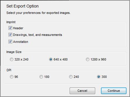
65 How to export images

66 1. Check the boxes that you want to imprint into the exported picture. 2. Select the image size you want. 3. Select image DPI. 4. Then Click Continue to proceed to the save as window to set name and folder for the image, to , or go to print menu. Selecting Cancel will stop the process. How to import and export drawings You can import and export drawings between pictures in the software. 1. Draw on an image using the draw tools. 2. Right click and select Export drawing. 3. Create a file name and press Save.

67 4. Open a new image and select Import Drawing


68 5. Locate the drawing you want to import then press Open.(eg. we will import Sample 1.atd) 6. The drawing is now imported onto the new image.

69 Auto Distance Measurement Quick Guide How to create auto distance measurement on DinoCapture 2.0. Step 1: Input a magnification, and then create the detection path for the edge detection indicator squares to travel by holding down the Ctrl key while using the Line measurement tool. Remember to release the Ctrl key when done drawing the line. Step 2: When the detection path is created, the Edge Detection Criteria window will pop up. Set the edge detection criteria for the edge detection indicator squares to follow.

70 Optional: Set validation rules for pass and fail analysis. Step 1: Click* on the detection path to select it, then right click on the detection path and select Validation Rule on the menu.
71 * When the mouse pointer becomes a pointing finger it means the item can be selected. Click on the item then the pointing finger will become an open hand and ready for editing (If it can t be selected, make sure NO draw or measurement tools are selected and try again). The item is also available for editing if changes need to be made after the first setup. Step 2: In the Measurement Data Validation window, set the data ranges and pictures** that indicate the data range. Three data ranges can be created while 1 is first priority.


72 **Show Picture window is selected from the Measurement Data Validation window and clicking on button under Show Picture column. IP Camera Mode Setup in DinoCapture 2.0 You can allow other people to remotely see your Dino-Lite or Dino-Eye by switching your live preview window into IP camera mode and also be able to view a remote Dino-Lite or Dino-Eye with the DinoCapture 2.0 software if they are in this mode too. IP camera mode is the live preview window of the Dino-Lite or Dino-Eye turned into a mode that allows others to see the live video feed in your local area network* or through the World Wide Web*. It is useful for situations where privacy is needed, as
73 the only way to connect to a remote Dino-Lite or Dino-Eye is to know the others IP address. It can be used for professions such as doctors who require doctor/ patient confidentiality, education where the teacher can see what the students are examining right away, and more. Switch to IP Camera Mode for others to see your Dino-Lite or Dino-Eye Turning your live preview window into IP camera mode allows remote DinoCapture 2.0 users to be able to view the live video feed of your Dino-Lite or Dino-Eye. Switching to IP Camera Mode: 1. Right click the live preview window 2. Select IP Camera Mode 3. Your live preview window will now change into IP camera mode and is now ready for remote DinoCapture 2.0 users to view your live video feed from your Dino-Lite or Dino-Eye. In this mode you can take pictures, add a password for additional security, and turn on/off the LED s on the Dino-lite. You can also see your LAN and WAN** IP address on the top left corner of the window to easily

74 identify your IP address for remote users (others) to connect to your Dino-Lite or Dino-Eye that has its live preview window in IP camera mode. If you are behind a firewall, please check the If behind a Firewall section of this instruction sheet. 4. When asking someone to connect to your Dino-Lite or Dino-Eye with its live preview window in IP camera mode through the internet*, have them type the WAN** IP address instead of the LAN** address when attempting to connect. When connecting through the intranet*, use the LAN IP address when connecting to other Dino-Lite or Dino-Eye that has its live preview window in IP camera mode. How to connect to a remote Dino-Lite or Dino-Eye You can connect to a remote Dino-Lite or Dino-Eye when its live preview window in IP Camera mode, which allows you to view the live video feed of a Dino-Lite or Dino-Eye over the internet or intranet with the DinoCapture 2.0 software. Connect to remote Dino-Lite or Dino-Eye: 1. Ensure the remote Dino-Lite or Dino-Eye you want to connect to have switched its live preview window into IP camera mode. 2. Select Settings 3. Move your mouse over to Connect to IP Dino-Lite or Dino-Eye
.")
. If you do not know which TCP Port are used already, you may want to use the default number. Camera No.")
75 4. Then click on New 5. The New Connection window will pop up where you can fill in information to connect to the remote Dino-Lite or Dino-Eye. Alias: Create a name for the remote Dino-Lite or Dino-Eye (When done, the name will be displayed in Recent ). IP: Enter the IP of the remote Dino-Lite or Dino-Eye that has its live preview window is in IP Camera mode. Port: Port reffers to TCP Port***. The default is but you can create your own number ( ). If you do not know which TCP Port are used already, you may want to use the default number. Camera No.: The assigned number of the Dino-Lite or Dino-Eye that has its live preview window in IP Camera mode (server). If only 1 Dino-Lite is connected normally 1 is the camera number.
76 Password: Enter password if a password was created. Connect: Connect to see if it works. If not connected, you will only see a black screen. Save: Save the settings of the remote Dino-Lite or Dino-Eye that can be recalled later on in Recent. Cancel: Cancel connection setup. If behind a Firewall The Dino-Lite or Dino-Eye whose live preview window is in IP camera mode cannot be detected by other DinoCapture 2.0 over the internet* if the router has a firewall. Set the router firewall to do Port Forwarding which is like a man made hole in the firewall that only exists if you create it. When behind a firewall, port forwarding will allow people to connect to YOUR Dino-Lite or Dino-Eye whose live preview window is in IP camera mode. Setup Port Forwarding: 1. First figure out your LAN** IP address and TCP Port***. Turn the live preview window into IP Camera Mode. The LAN and Port can be found on the top left corner of the window. 2. Set an IP address instead of a roaming IP address Change the Local Area Network Properties to use a set IP address instead of automatically obtaining a random IP address when connecting to the internet. 3. Set your router to port forward to the desired computer with the set IP address. Enter your router settings and have the router forward incoming internet traffic to your local computer while still be behind a firewall. 4. People can now connect to your Dino-Lite or Dino-Eye live preview window that is in IP camera mode.
77 Additional Information If one remote Dino-Lite or Dino-Eye has a password when in IP camera mode, then the other will also need to set a password to be able to connect. If you do not desire to use the default Port, you can change the TCP Port *** after creating a new connection. Simply double click to change it or change it in the Connection list. Amount of IP camera s you can connect to depend on your internet setting and system specification. For example 10/100mb internet speed connection allows you to connect to about 5 Dino-Lite or Dino-Eye in IP camera mode. If having trouble controlling the LED s on the Dino-Lite or Dino-Eye live preview window in IP Camera mode. Try disabling other video devices such as a built-in webcam and try again. If you have multiple IP addresses on one computer, the IP displayed in IP camera mode may not be correct. If so, you may find your IP address by searching it in Windows CMD: In Windows go to Run >Type: cmd > Type: ipconfig > under the section: Ethernet adapter Local Area Connection you can find your IP Address. You can open saved or recent remote Dino-Eye or Dino-Eye Connections. Recent: Selecting recent allows you to select or view the latest Dino-Lite or Dino-Eye that you have recently connected to. Open:
78 Selecting open allows you to modify the information stored regarding the remote Dino-Lite or Dino-Eye (Eg. password, port, and etc.), connect to the remote Dino-Lite/Dino-Eye, or delete the remote Dino-Lite/Dino-Eye from your list. Notes: *Intranet. An intranet is like a private network shared only with computers that are within that organization. Internet: The internet is the World Wide Web of interconnected computer networks with billions of users worldwide. ** LAN- local area network (IP created by router for local computers). WAN- wide area network (Real IP to connect to the World Wide Web). ***Port =TCP Port= Transmission Control Protocol Port. See Fig.1. Fig.1 Transparency Mode Up to four pictures can be changed into transparency mode. To enter the mode, right click an open picture and select Transparency Mode. To exit, right click again and select Exit. Use Ctrl + UP/DOWN or the mouse wheel to increase and decrease opacity when in transparency mode.

79 How to rename measurements You can rename a measurement by selecting a measurement. Then right click and click Rename.


80 Then a window will pop up allowing you to edit the name. Geotagging Photo You can add GPS coordinates on pictures taken or edit coordinates on pictures that already have GPS location. Click on an open image and select Geotagging photo, after that the Location Editor will pop up for you to enter GPS coordinates. When done, you can see the location by pressing the show location icon on bottom right side of the image.

81 See Also: External GPS How to use EDR (Extended Dynamic Range) In the active live video window, click on EDR it finished processing. and do not move the target until Information about EDR: EDR is a capture tool for the Dino-Lite Edge AM4815 series that when used, can improve visible information on subjects that varies greatly in brightness levels. It works by capturing and stacking 2-3 images with different exposure and help equalize the hard contrasts for a more natural image with less extremes for a more clear and detailed image. How to use EDOF (Extended Depth of Field) EDOF (Extended depth of field) is an image capture tool for the Dino-Lite Edge AM4815 series that improves images of uneven surfaces by taking a series of images at different focal depths and then automatically (or manually) stacking them in a single composite image. EDOF (Automatic) 1. Place the mouse pointer over the EDOF button.
 1. Place the mouse pointer over the EDOF button. 2.")
82 2. Scroll the mouse wheel to the desired amount of focal depth. (The more bars shown, the greater the focal depth). 3. Click the mouse to start the EDOF process. Do not touch the Dino-Lite microscope or specimen during this process. EDOF (Manual) 1. Place the mouse pointer over the EDOF button. 2. Scroll the mouse wheel until the focal depth bars are replaced by the word MANUAL. 3. Click the mouse and the EDOF-manual mode window will open. 4. Capture multiple (up to 11) images at different focal points. Change the focus using the Focus bar slider or the Increment button. Clicking the Increment button changes the focus by the number of points shown in the Increment box. 5. Click on the Start processing button to start the EDOF process. Do not touch the Dino-Lite microscope or specimen during this process. Viewing an EDOF image View the image with extended depth or by holding the Ctrl key on the keyboard, the EDOF image will show the original best focused image at the mouse cursor s position before stacking, and the mouse wheel can also be used for finding the upper or
83 lower image layer. This feature would allow the user to recover the 3D feeling which is lost by the stacked image. The image taken by EDOF should be found in the image list noted EDOF in the header. Like a normal picture, the EDOF image can have annotation and drawing, but not measurements (because the magnification is varied with focus). How to use Manual and Automatic Refocus The Manual and Automatic Refocus for the Dino-Lite Edge AM4815 Series is for brief observations or captures on points of interest near the proximity of the initial focused depth. Below describes how they are used: Automatic Refocus Hold the Ctrl key, then click on an area of interest in the live preview and the camera will attempt to focus at the selected depth. Releasing the Ctrl key to reverts back to the original focused depth. Manual Refocus Hold the Ctrl key, and then scroll the mouse wheel when in the live preview window to focus at depths above or below the initial focus. back to the original focused depth. Releasing the Ctrl key reverts Update: A new way of using EDOF refocus mode is now provided by pressing the scroll wheel during either live video or EDOF image preview as an alternative to CTRL+left clicks. To leave the refocus mode, simply left-clicking the mouse. - The activation of EDOF refocus mode can be identified by the appearance of cursor or the text of Refocus Mode at the lower-right corner. - Under EDOF refocus mode, the Focus Shift information is shown on EDOF image which displays the focal difference between the refocused and original focus positions. The Focus Shift may vary with the entered magnification rate and it is provided as reference for the depth information.


84 How to add a camera label 1. Right click on a live preview window. 2. Input the label for the camera then press OK. 3. The label will be displayed next to the name of the Dino-Lite. Notice: The camera label displays only on the USB port the label was created. Keyboard Controls Keyboard Controls Keyboard controls provide more ease and practicality with the DinoCapture 2.0 experience.
85 Delete key You can delete pictures on the image list simply by pressing the Delete key. You can also delete selected or active annotations and measurements with the Delete key. F6 Key Holding down the F6 key on the keyboard allows to continuously taking pictures until the button is decompressed. F7 Key Pressing the F7 on the keyboard opens the time-lapsed window. F8 Key Pressing F8 freezes the live video feed of all Dino-Lite. F9 Key Pressing F9 simultaneously takes a snapshot with all live Dino-Lite. F10 Key Pressing the F10 on the keyboard to enters full screen mode. Press F10 again to exit. F11 Key Pressing the F11 on the keyboard takes a snapshot of the specimen in the active video window.
86 F12 Key Pressing the F12 key on the keyboard lets you start recording a video. Pressing the F12 key again stops the recording. Ctrl+A Pressing Ctrl+A selects all files on the image list. Ctrl+W Next window on preview window management bar becomes active window. Ctrl+Z Undo last drawing or measurement. Ctrl+F4 Close a preview window. Ctrl+Tab Next window on preview window management bar becomes active window. Alt+F4 Exits DinoCapture 2.0.
87 Esc Abort using tools. Shift and Left Mouse Button Holding the Shift key and clicking on the first and last images desired; highlights the group of images. See Also: Deleting consecutive pictures Ctrl and Left Mouse Button Highlight desired pictures by holding the Ctrl key and select desired pictures or video by pressing the left mouse button. See Also: Deleting multiple pictures Arrow keys With the magnifier active, use the arrow keys to move the cursor pixel by pixel for precision movement. See Also: Magnifier Mouse Controls
88 Opening a picture To open a picture, you can simply DOUBLE click its thumbnail. Moving a window When you hold down the left mouse button on a child window, you can drag the window anywhere within the main window. Stopping continuous line and polygon measurements DOUBLE left clicking stops the continuous line and polygon measurements. Starting a live video feed Double clicking the camera icon on the preview window management bar starts a live video feed. For example if one Dino-Lite is plugged in, double click the thumbnail and the live video will start. See also: Preview Window Management Bar Taking a picture You can also DOUBLE left click to take a picture in the live video window other than the picture button. Digital 2x Zoom Scroll the mouse wheel to digitally zoom-in/ out when the pointer is in a live preview or image with resolution higher than 1280 x 960.
89 Measurement Properties About the measurement property window The measurement property window organizes and shows the status of all the measurements as well the ability to adjust how the results are shown on the image. Notice: The measurement and calibration feature is only available for certain models. Please contact a local sales representative for further information. The Tabs The DinoCapture 2.0 software separates each type of measurements into tabs helping you to organize your measurements. Line The Line tab shows all the properties of the line measurements as well as the ability to select what information is shown on the image, ability to delete, change units of measurement, and also export data to excel.
90 Polygon The Polygon tab shows all the properties of the polygon measurements. As well as the ability to select what information is shown on the image, ability to delete, change units of measurement, and also export data to excel. Circle The Circle tab shows all the properties of the circle measurements. As well as the ability to select what information is shown on the image, ability to delete, change units of measurement, and also export data to excel. Arc The Arc tab shows all the properties of the arc measurements. As well as the ability to select what information is shown on the image, ability to delete, change units of measurement, and also export data to excel. Angle The Angle tab shows all the properties of the angle measurements. As well as the ability to select what information is shown on the image, ability to delete, change units of measurement, and also export data to excel. Categories
91 Show -The show checkbox let you see the measurement results for the selected measurement on the image. Deselecting the checkbox hides the selected measurement results. Name -Displays the name of the measurement. Length -Displays the length of the measurement (L). Area - Displays the area of the measurement (A). Radius -Displays the radius of the measurement (r). Angle (deg) -Displays the angle of the measurement ( ). Unit -Displays the unit of measure on the picture
92 Display The display check boxes control what you would be able to see on the picture. Only the values that are relevant to the type of measurement are available for selection, the others are grayed out. Un-checking and checking the boxes controls all measurements of the same type. Name -Display the name of the measurement. Length - Display the length of a measurement. Area -Display the area of a measurement. Radius -Display the radius/diameter of a measurement.
 - Available when using High Quality drawing mode, this")
 - Added adjustable opacity to the measurement text box under High Quality drawing mode.")
93 Angle -Display the angle of a measurement. Unit -Display the unit of measure next to the results Opacity (alpha) - Available when using High Quality drawing mode, this controls the amount of opacity for the displayed measurements and drawings. The higher the number, the less transparent it is. Background Opacity (alpha) - Added adjustable opacity to the measurement text box under High Quality drawing mode. It can be adjusted by changing the Background Opacity (alpha) value in the Measurement Properties window.

94 Buttons Decimals Select the decimal places to be shown on measurements. 1= 1 decimal places= = 2 decimal places = =3 decimal places = =4 decimal places = Delete Select a measurement and click on Delete to remove the measurement. Clear all measurements and drawing Clear all measurements and drawings on the active window. Export to excel Exports data from the active window to Excel.
95 Close The X on the top right corner closes the measurement properties window. Go to settings and select Measurement Properties to reopen the window. Camera Adjustment About Camera Adjustment Press the button on the video preview window to open the camera adjustment window. The camera adjustment window controls the live video settings. The buttons on the bottom of the camera adjustment window allow you to Import or Export video settings, or restore Default settings. There is also an option to Load the current setting on startup. Once you have made your selections, click the OK button to confirm and close this window.

96 Camera Adjustment Window Note: The camera adjustment window settings vary depending on the model. For example Dino-Lite Premier Series can export or import your settings so you can save the setting for anther time by exporting the setting or importing a setting from a previous time.

97 Camera Color Adjustment Settings Monochrome Setting This setting applies a grayscale effect, as shown in the pictures below. Monochrome setting disabled Monochrome setting enabled

98 Negative Setting This setting applies a color negative effect, as shown in the pictures below. Negative setting disabled Negative setting enabled
99 Microtouch controls The MicroTouch (touch sensitive static sensor) feature on the handheld digital microscope gives users the option of taking a picture right from the microscope itself. The MicroTouch tool is activated when you touch the MicroTouch trigger after starting the DinoCapture 2.0 software. After the software recognized that the Dino-Lite has the MicroTouch feature, you can activate or deactivate the MicroTouch controls with this button. The MicroTouch was designed to minimize image blur while taking a picture with the microscope. Great for those moments when you need to take a picture, but have a hard time reaching the computer Notice: Not all models have the MicroTouch feature. Please contact a local sales representative for more information. Picture Adjust About the picture adjust window The picture adjust window allows you to change the picture colors and qualities. To open the picture adjust window, press the setting button when the active window is a picture.

100 Picture Adjust Adjust the color properties of the selected picture. Contrast You can adjust the contrast of the picture. Brightness You can adjust the brightness of the picture. Saturation You can adjust the saturation of the picture.
101 Hue You can adjust the hue of the picture. Gamma You can adjust the gamma of the picture. Sharpness Allows you to adjust the sharpness of the selected picture. Range You can change the range of the sharpness. Strength You can adjust the strength of the pixel. Picture Adjust Buttons Default Resets the picture settings back to default. Save

102 Saves the adjusted picture settings and closes the picture adjust window. Cancel Closes the picture adjust window without saving changes. Folder Manager Folder Manager You can create, import previous, or delete save folders in the Folder Manager window. See also: Import Folder How to create a new folder New Allows creation of a new save folder for DinoCapture 2.0.
DINOCAPTURE 2.0. Legacy updates, fixes & release notes JULY 21, Visual & Optical Solutions
 DINOCAPTURE 2.0 Legacy updates, fixes & release notes JULY 21, 2017 WWW.DINOLITE.SG Visual & Optical Solutions DinoCapture 2.0 version 1.5.22.C Release Notes (2017-07-10) Added display of coverage map
DinoCapture Additional Software Instructions for Measurement models
 DinoCapture Additional Software Instructions for Measurement models Window tools Microtouch: The microtouch is a touch sensitive area on the dome that connects to the USB Cable. It functions as a button
DinoCapture Additional Software Instructions
 DinoCapture Additional Software Instructions Window tools Microtouch: The microtouch is a touch sensitive area on the dome that connects to the USB Cable. It functions as a button that lets you take pictures
ezimagex2 User s Guide Version 1.0
 ezimagex2 User s Guide Version 1.0 Copyright and Trademark Information The products described in this document are copyrighted works of AVEN, Inc. 2015 AVEN, Inc. 4595 Platt Rd Ann Arbor, MI 48108 All
Motic Images Plus 3.0 ML Software. Windows OS User Manual
 Motic Images Plus 3.0 ML Software Windows OS User Manual Motic Images Plus 3.0 ML Software Windows OS User Manual CONTENTS (Linked) Introduction 05 Menus and tools 05 File 06 New 06 Open 07 Save 07 Save
This guide will help you with many of the basics of operation for your Epson 485wi BrightLink Projector with interactive functionality.
 This guide will help you with many of the basics of operation for your Epson 485wi BrightLink Projector with interactive functionality. If you need further assistance with questions, you can refer to the
SI-100 Digital Microscope. User Manual
 SI-100 Digital Microscope User Manual Read this manual before use Keep for future reference Content 1 Introduction... 3 1.1 About The SI-100... 3 1.2 Advantage of SI-100... 3 1.3 Product Specification...
Dino-Lite Digital Microscope User Manual. User Manual
 User Manual Dino-Lite Digital Microscope User Manual Table of Contents Chapter 1 - Getting Started 1.1 Installation Instructions for Windows XP...1 1.2 Instructions for Windows Vista Users...8 Chapter
Contents escope Software Guide Execute Software Calibration and Measurement escope Software Interface Instructions Main Interface
 Contents escope Software Guide Execute Software...3 Capture Photo...3 Capture Video...3 Time-lapsed Picture / Video...4 Picture / Video Save as...4 Calibration and Measurement Calibration...5 Measurement...7
End User Guide. 2.1 Getting Started Toolbar Right-click Contextual Menu Navigation Panels... 2
 TABLE OF CONTENTS 1 OVERVIEW...1 2 WEB VIEWER DEMO ON DESKTOP...1 2.1 Getting Started... 1 2.1.1 Toolbar... 1 2.1.2 Right-click Contextual Menu... 2 2.1.3 Navigation Panels... 2 2.1.4 Floating Toolbar...
Quick Guide for Photoshop CC Basics April 2016 Training:
 Photoshop CC Basics Creating a New File 1. Click File > New 2. Keep Default Photoshop Size selected in the Preset drop-down list. 3. Click OK. Showing Rulers 1. On the Menu bar, click View. 2. Click Rulers.
Microsoft PowerPoint 2013 Beginning
 Microsoft PowerPoint 2013 Beginning PowerPoint Presentations on the Web... 2 Starting PowerPoint... 2 Opening a Presentation... 2 File Tab... 3 Quick Access Toolbar... 3 The Ribbon... 4 Keyboard Shortcuts...
CS Multimedia and Communications REMEMBER TO BRING YOUR MEMORY STICK TO EVERY LAB! Lab 02: Introduction to Photoshop Part 1
 CS 1033 Multimedia and Communications REMEMBER TO BRING YOUR MEMORY STICK TO EVERY LAB! Lab 02: Introduction to Photoshop Part 1 Upon completion of this lab, you should be able to: Open, create new, save
Vision Pointer Tools
 Vision Pointer Tools Pointer Tools - Uses Pointer Tools can be used in a variety of ways: during a Vision Demo to annotate on the master station s screen during a Remote Control session to annotate on
DinoXcope User Manual
 DinoXcope User Manual Contents 1 System Requirements 1 Installation 2 Adding a time stamp to the live view 3 Capturing an image 4 Creating a real time movie 5 Creating a time-lapse movie 6 Drawing on an
Keynote 08 Basics Website:
 Website: http://etc.usf.edu/te/ Keynote is Apple's presentation application. Keynote is installed as part of the iwork suite, which also includes the word processing program Pages and the spreadsheet program
Acrobat X Professional
 Acrobat X Professional Toolbar Well Page Navigations/Page Indicator Buttons for paging through document Scroll Bar/box page indicator appears when using the scroll button to navigate. When you release
OnPoint s Guide to MimioStudio 9
 1 OnPoint s Guide to MimioStudio 9 Getting started with MimioStudio 9 Mimio Studio 9 Notebook Overview.... 2 MimioStudio 9 Notebook...... 3 MimioStudio 9 ActivityWizard.. 4 MimioStudio 9 Tools Overview......
XnView Image Viewer. a ZOOMERS guide
 XnView Image Viewer a ZOOMERS guide Introduction...2 Browser Mode... 5 Image View Mode...14 Printing... 22 Image Editing...26 Configuration... 34 Note that this guide is for XnView version 1.8. The current
StickFont Editor v1.01 User Manual. Copyright 2012 NCPlot Software LLC
 StickFont Editor v1.01 User Manual Copyright 2012 NCPlot Software LLC StickFont Editor Manual Table of Contents Welcome... 1 Registering StickFont Editor... 3 Getting Started... 5 Getting Started...
XnView 1.9. a ZOOMERS guide. Introduction...2 Browser Mode... 5 Image View Mode...15 Printing Image Editing...28 Configuration...
 XnView 1.9 a ZOOMERS guide Introduction...2 Browser Mode... 5 Image View Mode...15 Printing... 22 Image Editing...28 Configuration... 36 Written by Chorlton Workshop for hsbp Introduction This is a guide
Using IPACS Webserver:
 Using IPACS Webserver: Logging On: The IPACS Webserver can be accessed from any PC with internet connectivity. 1. Open Internet Explorer or your internet service provider. 2. Type the IPACS web address
Libraries. Multi-Touch. Aero Peek. Sema Foundation 10 Classes 2 nd Exam Review ICT Department 5/22/ Lesson - 15
 10 Classes 2 nd Exam Review Lesson - 15 Introduction Windows 7, previous version of the latest version (Windows 8.1) of Microsoft Windows, was produced for use on personal computers, including home and
SeeSnake HQ User Guide
 SeeSnake HQ User Guide SeeSnake HQ Version 1.53.85.1426 23 May 2010 About SeeSnake HQ 3 Digital Technology 3 Installation and Updates 5 Windows XP 5 Windows Vista 5 Windows 7 5 The Home Window 6 Home Toolbar
The Fundamentals. Document Basics
 3 The Fundamentals Opening a Program... 3 Similarities in All Programs... 3 It's On Now What?...4 Making things easier to see.. 4 Adjusting Text Size.....4 My Computer. 4 Control Panel... 5 Accessibility
HYPERSTUDIO TOOLS. THE GRAPHIC TOOL Use this tool to select graphics to edit. SPRAY PAINT CAN Scatter lots of tiny dots with this tool.
 THE BROWSE TOOL Us it to go through the stack and click on buttons THE BUTTON TOOL Use this tool to select buttons to edit.. RECTANGLE TOOL This tool lets you capture a rectangular area to copy, cut, move,
Keynote Basics Website:
 Keynote Basics Website: http://etc.usf.edu/te/ Keynote is Apple's presentation application. Keynote is installed as part of the iwork suite, which also includes the word processing program Pages. If you
User Manual Version 1.1 January 2015
 User Manual Version 1.1 January 2015 - 2 / 112 - V1.1 Variegator... 7 Variegator Features... 7 1. Variable elements... 7 2. Static elements... 7 3. Element Manipulation... 7 4. Document Formats... 7 5.
Designer Reference 1
 Designer Reference 1 Table of Contents USE OF THE DESIGNER...4 KEYBOARD SHORTCUTS...5 Shortcuts...5 Keyboard Hints...5 MENUS...7 File Menu...7 Edit Menu...8 Favorites Menu...9 Document Menu...10 Item Menu...12
Introduction to Microsoft Office PowerPoint 2010
 Introduction to Microsoft Office PowerPoint 2010 TABLE OF CONTENTS Open PowerPoint 2010... 1 About the Editing Screen... 1 Create a Title Slide... 6 Save Your Presentation... 6 Create a New Slide... 7
AutoCAD 2009 User InterfaceChapter1:
 AutoCAD 2009 User InterfaceChapter1: Chapter 1 The AutoCAD 2009 interface has been enhanced to make AutoCAD even easier to use, while making as much screen space available as possible. In this chapter,
How To Capture Screen Shots
 What Is FastStone Capture? FastStone Capture is a program that can be used to capture screen images that you want to place in a document, a brochure, an e-mail message, a slide show and for lots of other
W-E
 Signage Suite V2.20 User Guide 605220-02-01-W-E-051613-02 Trademarks Windows XP, Windows Vista, Windows 7, and Microsoft are registered trademarks of Microsoft Corporation. All other trademarks are the
After completing this lesson, you will be able to:
 LEARNING OBJECTIVES After completing this lesson, you will be able to: 1. Create a template. 2. Understand the AutoCAD Window. 3. Understand the use of the function keys. 4. Select commands using the Pull-down
MINT Interactive User s Guide
 MINT Interactive User s Guide MINT Interactive is very powerful board software including rich functions and gallery software, which are very useful for lecture environment. It will be continuously upgraded
Chaos Culture. Multiclip Editor / Multiclip Note preview 1.5. Edited by Jason Cowling
 Chaos Culture Introduction... 2 Important stuff... 2 Setup... 3 Editing clips... 4 Using the editor... 5 Settings... 9 Workflow settings... 10 Performance... 13 Future updates... 13 Editor 1.6.61 / Note
Welcome to MicroStation
 Welcome to MicroStation Module Overview This module will help a new user become familiar with the tools and features found in the MicroStation design environment. Module Prerequisites Fundamental knowledge
OpenForms360 Validation User Guide Notable Solutions Inc.
 OpenForms360 Validation User Guide 2011 Notable Solutions Inc. 1 T A B L E O F C O N T EN T S Introduction...5 What is OpenForms360 Validation?... 5 Using OpenForms360 Validation... 5 Features at a glance...
Digital Microscopes Zoomy 2.0 Digital Microscope What software/devices will I need to use a Zoomy? Connecting Zoomy 2.0
 Digital Microscopes Zoomy 2.0 Digital Microscope Zoomy 2.0 is a handheld digital microscope that children can use to examine objects. Zoomy plugs into a computer using a built in USB cable. The computer
Impress Guide Chapter 11 Setting Up and Customizing Impress
 Impress Guide Chapter 11 Setting Up and Customizing Impress This PDF is designed to be read onscreen, two pages at a time. If you want to print a copy, your PDF viewer should have an option for printing
Numbers Basics Website:
 Website: http://etc.usf.edu/te/ Numbers is Apple's new spreadsheet application. It is installed as part of the iwork suite, which also includes the word processing program Pages and the presentation program
Working with PDF s. To open a recent file on the Start screen, double click on the file name.
 Working with PDF s Acrobat DC Start Screen (Home Tab) When Acrobat opens, the Acrobat Start screen (Home Tab) populates displaying a list of recently opened files. The search feature on the top of the
INSERVICE DAY - 11/11/11 TECHNOLOGY
 INSERVICE DAY - 11/11/11 TECHNOLOGY Converting PowerPoints into Movies (examples using imovie& Windows MovieMaker) (More detailed tutorials with pictures can be found at http://www.whsd.net/olc/teacher.aspx?s=1452).
How To Capture Screen Shots
 What Is FastStone Capture? FastStone Capture is a program that can be used to capture screen images that you want to place in a document, a brochure, an e-mail message, a slide show and for lots of other
Chaos Culture. MIDI Modulators / Multiclip Note preview 1.6. Edited by Jason Cowling
 Chaos Culture Introduction... 2 Important stuff... 2 Setup... 3 Editing clips... 4 Using the editor... 5 Modulators... 8 Settings... 9 Work$ow settings... 10 Performance... 13 Future updates... 13 1.8.99
Colony Counting User Manual A D I V I S I O N O F S Y N O P T I C S L T D
 ProtoCOL Colony Counting User Manual S Y N B I O S I S A D I V I S I O N O F S Y N O P T I C S L T D All possible care has been taken in the preparation of this publication, but Synoptics Limited accepts
Microsoft PowerPoint 2007 Beginning
 Microsoft PowerPoint 2007 Beginning Educational Technology Center PowerPoint Presentations on the Web... 2 Starting PowerPoint... 2 Opening a Presentation... 2 Microsoft Office Button... 3 Quick Access
Bombardier Business Aircraft Customer Services. Technical Publications. SmartPubs Viewer 3.0 User Guide. Updated January 2013 [2013]
![Bombardier Business Aircraft Customer Services. Technical Publications. SmartPubs Viewer 3.0 User Guide. Updated January 2013 [2013]](/thumbs/90/103657167.jpg "Bombardier Business Aircraft Customer Services. Technical Publications. SmartPubs Viewer 3.0 User Guide. Updated January 2013 [2013]") Bombardier Business Aircraft Customer Services Technical Publications SmartPubs Viewer 3.0 User Guide Updated January 2013 [2013] Table of Contents Application Views... 5 Collection View... 5 Manual View...
Bombardier Business Aircraft Customer Services Technical Publications SmartPubs Viewer 3.0 User Guide Updated January 2013 [2013] Table of Contents Application Views... 5 Collection View... 5 Manual View...
User Manual. pdoc Pro Client for Windows. Version 2.1. Last Update: March 20, Copyright 2018 Topaz Systems Inc. All rights reserved.
 User Manual pdoc Pro Client for Windows Version 2.1 Last Update: March 20, 2018 Copyright 2018 Topaz Systems Inc. All rights reserved. For Topaz Systems, Inc. trademarks and patents, visit www.topazsystems.com/legal.
Microsoft PowerPoint 2010 Beginning
 Microsoft PowerPoint 2010 Beginning PowerPoint Presentations on the Web... 2 Starting PowerPoint... 2 Opening a Presentation... 2 File Tab... 3 Quick Access Toolbar... 3 The Ribbon... 4 Keyboard Shortcuts...
GOM Cam User Guide. Please visit our website (cam.gomlab.com) regularly to check out our. latest update.
 regularly to check out our. latest update.") GOM Cam User Guide Please visit our website (cam.gomlab.com) regularly to check out our latest update. From screen recording to webcam video and gameplay recording GOM Cam allows you to record anything
GOM Cam User Guide Please visit our website (cam.gomlab.com) regularly to check out our latest update. From screen recording to webcam video and gameplay recording GOM Cam allows you to record anything
1 ZoomBrowser EX Software User Guide 5.0
 1 ZoomBrowser EX Software User Guide 5.0 Table of Contents (1/2) Chapter 1 Chapter 2 Chapter 3 What is ZoomBrowser EX? What Can ZoomBrowser EX Do?... 4 Guide to the ZoomBrowser EX Windows... 5 Task Buttons
Photoshop tutorial: Final Product in Photoshop:
 Disclaimer: There are many, many ways to approach web design. This tutorial is neither the most cutting-edge nor most efficient. Instead, this tutorial is set-up to show you as many functions in Photoshop
CAPTURE. USER GUIDE v1
 CAPTURE USER GUIDE v1 INTRODUCTION About The Logitech Capture app makes creating content with your webcam as easy as lights, camera, Capture. Start recording high-quality videos the second you plug in
2. To change the view of the pictures, click the Thumbnail View button.
 1 2 3 4 5 7 6 8 9 1. Click the down arrow to find your picture(s). 2. To change the view of the pictures, click the Thumbnail View button. 3. If you are only resizing ONE picture: Click on the picture
PowerPoint 2016 Building a Presentation
 PowerPoint 2016 Building a Presentation What is PowerPoint? PowerPoint is presentation software that helps users quickly and efficiently create dynamic, professional-looking presentations through the use
[Not for Circulation] This document provides a variety of shortcuts for working in PowerPoint 2007.
![[Not for Circulation] This document provides a variety of shortcuts for working in PowerPoint 2007.](/thumbs/72/67772637.jpg "[Not for Circulation] This document provides a variety of shortcuts for working in PowerPoint 2007.") PowerPoint Shortcuts This document provides a variety of shortcuts for working in PowerPoint 2007. Using Slides from Other Presentations To add a slide from an existing presentation to the current presentation,
PowerPoint Shortcuts This document provides a variety of shortcuts for working in PowerPoint 2007. Using Slides from Other Presentations To add a slide from an existing presentation to the current presentation,
Getting Started. Microsoft QUICK Source 7
 Microsoft QUICK Windows Source 7 Getting Started The Windows 7 Desktop u v w x u Icon links to a program, file, or folder that is stored on the desktop. v Shortcut Icon links to a program, file, or folder
Mouse Navigation. Middle Button (wheel) Pan. Click + Drag. Re-Center View. Double-Click. Context Menu. Tool Operation. Click. Click. Multi-Select.
 Pan. Click + Drag. Re-Center View. Double-Click. Context Menu. Tool Operation. Click. Click. Multi-Select.") BLUEBEAM REVU KEYBOARD SHORTCUTS Mouse Navigation Middle Button (wheel) Pan Re-Center View Click + Drag Double-Click Left Button Right Button Tool Operation Click Context Menu Click Pan Click + Spacebar
BLUEBEAM REVU KEYBOARD SHORTCUTS Mouse Navigation Middle Button (wheel) Pan Re-Center View Click + Drag Double-Click Left Button Right Button Tool Operation Click Context Menu Click Pan Click + Spacebar
Using Flash Animation Basics
 Using Flash Contents Using Flash... 1 Animation Basics... 1 Exercise 1. Creating a Symbol... 2 Exercise 2. Working with Layers... 4 Exercise 3. Using the Timeline... 6 Exercise 4. Previewing an animation...
Vision MET/METCAD. 2D measurement system
 Vision MET/METCAD 2D measurement system September 2012 ~ Contents ~ 1 GENERAL INFORMATION:... 3 1.1 PRECISION AND RESOLUTION... 3 2 GETTING STARTED:... 5 2.1 USER IDENTIFICATION... 5 2.2 MAIN WINDOW OF
Outlook Web Access. In the next step, enter your address and password to gain access to your Outlook Web Access account.
 Outlook Web Access To access your mail, open Internet Explorer and type in the address http://www.scs.sk.ca/exchange as seen below. (Other browsers will work but there is some loss of functionality) In
BUCKVIEW Advanced. User Guide
 BUCKVIEW Advanced User Guide Inside This Manual I. Inside This Manual... 2 II. Viewing and Managing Your Images... 3 Manage Image Folders...5 Manage Sites...6 Manage Locations...10 Erase Memory Card...14
Kidspiration 3 Basics Website:
 Website: http://etc.usf.edu/te/ Kidspiration is the visual learning tool for K-5 learners from the makers of Inspiration. With Kidspiration, students can build graphic organizers such as webs, concept
SMART Meeting Pro PE 4.1 software
 Help us make this document better smarttech.com/feedback/170973 SMART Meeting Pro PE 4.1 software USER S GUIDE Product registration If you register your SMART product, we ll notify you of new features
VarioAnalyze. User Manual. JENOPTIK Group.
 VarioAnalyze User Manual JENOPTIK Group. Dear User Dear User You should carefully read these instructions before you start operating the VarioAnalyze Software. Editorial deadline: October 2005 Document
IMAGE STUDIO LITE. Tutorial Guide Featuring Image Studio Analysis Software Version 3.1
 IMAGE STUDIO LITE Tutorial Guide Featuring Image Studio Analysis Software Version 3.1 Notice The information contained in this document is subject to change without notice. LI-COR MAKES NO WARRANTY OF
CHAPTER 1 COPYRIGHTED MATERIAL. Getting to Know AutoCAD. Opening a new drawing. Getting familiar with the AutoCAD and AutoCAD LT Graphics windows
 CHAPTER 1 Getting to Know AutoCAD Opening a new drawing Getting familiar with the AutoCAD and AutoCAD LT Graphics windows Modifying the display Displaying and arranging toolbars COPYRIGHTED MATERIAL 2
Getting Started. In This Chapter
 Getting Started In This Chapter 2 This chapter introduces concepts and procedures that help you get started with AutoCAD. You learn how to open, close, and manage your drawings. You also learn about the
Edupen Pro User Manual
 Edupen Pro User Manual (software for interactive LCD/LED displays and monitors) Ver. 3 www.ahatouch.com Some services in Edupen Pro require dual touch capability. In order to use dual touch, your computer
Tutorial 1 Engraved Brass Plate R
 Getting Started With Tutorial 1 Engraved Brass Plate R4-090123 Table of Contents What is V-Carving?... 2 What the software allows you to do... 3 What file formats can be used?... 3 Getting Help... 3 Overview
Autodesk Inventor Design Exercise 2: F1 Team Challenge Car Developed by Tim Varner Synergis Technologies
 Autodesk Inventor Design Exercise 2: F1 Team Challenge Car Developed by Tim Varner Synergis Technologies Tim Varner - 2004 The Inventor User Interface Command Panel Lists the commands that are currently
Exercise Guide. Published: August MecSoft Corpotation
 VisualCAD Exercise Guide Published: August 2018 MecSoft Corpotation Copyright 1998-2018 VisualCAD 2018 Exercise Guide by Mecsoft Corporation User Notes: Contents 2 Table of Contents About this Guide 4
HAPPY HOLIDAYS PHOTO BORDER
 HAPPY HOLIDAYS PHOTO BORDER In this Photoshop tutorial, we ll learn how to create a simple and fun Happy Holidays winter photo border! Photoshop ships with some great snowflake shapes that we can use in
Table of Contents. Logos Imaging Application User s Manual Version Page 1
 Table of Contents About... 4 System Requirements... 5 Uninstall Previous Versions... 5 Install LIA 6.0... 6 Install the Device Drivers... 13 Register... 14 Getting Help... 14 Technical Support... 14 Workspace
HOW TO. In this section, you will find. miscellaneous handouts that explain. HOW TO do various things.
 In this section, you will find miscellaneous handouts that explain do various things. 140 SAVING Introduction Every time you do something, you should save it on the DESKTOP. Click Save and then click on
DDX-R Quick Start Guide
 DDX-R Quick Start Guide Imaging Support 1-855-726-9995 www.scilvet.com Contents USING DDX-R... 2 Opening a Patient File... 2 Opening a New Patient File... 3 Screen Layout... 3 ACQUIRING IMAGES ON A PATIENT...
ENVI Tutorial: Introduction to ENVI
 ENVI Tutorial: Introduction to ENVI Table of Contents OVERVIEW OF THIS TUTORIAL...1 GETTING STARTED WITH ENVI...1 Starting ENVI...1 Starting ENVI on Windows Machines...1 Starting ENVI in UNIX...1 Starting
Customisation and production of Badges. Getting started with I-Color System Basic Light
 Customisation and production of Badges Getting started with I-Color System Basic Light Table of contents 1 Creating a Badge Model 1.1 Configuration of Badge Format 1.2 Designing your Badge Model 1.2.1
Tutorial 01 Quick Start Tutorial
 Tutorial 01 Quick Start Tutorial Homogeneous single material slope No water pressure (dry) Circular slip surface search (Grid Search) Intro to multi scenario modeling Introduction Model This quick start
Automated Video Redaction User Guide
 Automated Video Redaction User Guide INTRODUCTION VIEVU s Automated Video Redaction (AVR) module is the next generation, fully-hosted, cloud evidence redaction system. This guide describes how to operate
Operating Instructions
 Providing presentation solutions V iewer Software Program Operating Instructions NIPPON AVIONICS CO., LTD. 1 This manual describes the functions and operations for conducting presentations using ip Viewer.
5.2. Click these tabs to jump to the Table of Contents, Index or start of each chapter.
 5.2 Click these tabs to jump to the, or start of each chapter. Click this button to advance to the next page. Click this button to return to the previous page. (Since this is the starting page, the [Back]
Vizit Pro User Manual
 Vizit Pro User Manual 1 Table of Contents Vizit Pro User Manual... 1 Using Vizit Pro... 3 The Vizit Pro User Interface... 3 Toolbars... 4 File Tab Toolbar... 4 Edit Tab Toolbar... 5 Annotations Tab Toolbar...
User s Guide. Valvova Oy
 User s Guide Valvova Oy June 21, 2017 CONTENTS Contents 1 Timeline 2 1.1 Program startup......................................... 3 1.2 Calendar............................................. 3 1.3 Go to
SMART Meeting Pro 4.2 personal license USER S GUIDE
 smarttech.com/docfeedback/170973 SMART Meeting Pro 4.2 personal license USER S GUIDE Product registration If you register your SMART product, we ll notify you of new features and software upgrades. Register
Adobe photoshop Using Masks for Illustration Effects
 Adobe photoshop Using Masks for Illustration Effects PS Preview Overview In this exercise you ll see a more illustrative use of Photoshop. You ll combine existing photos with digital art created from scratch
The Department of Construction Management and Civil Engineering Technology CMCE-1110 Construction Drawings 1 Lecture Introduction to AutoCAD What is
 The Department of Construction Management and Civil Engineering Technology CMCE-1110 Construction Drawings 1 Lecture Introduction to AutoCAD What is AutoCAD? The term CAD (Computer Aided Design /Drafting)
K e y b o a r d s h o rt c ut s
 Keyboard shortcuts Mouse navigation Middle button (wheel) Click + drag = pan Double-click = re-center view Left button Click = tool operation Click + spacebar = pan Shift + click + drag = multi-select
40. Sim Module - Common Tools
 HSC Sim Common Tools 15021-ORC-J 1 (33) 40. Sim Module - Common Tools Table of Contents 40.1. Drawing flowsheets and adding tables to flowsheets... 2 40.1.1. Drawing units... 2 40.1.2. Drawing streams...
Using Masks for Illustration Effects
 These instructions were written for Photoshop CS4 but things should work the same or similarly in most recent versions Photoshop. 1. To download the files you ll use in this exercise please visit: http:///goodies.html
ENVI Classic Tutorial: A Quick Start to ENVI Classic
 ENVI Classic Tutorial: A Quick Start to ENVI Classic A Quick Start to ENVI Classic 2 Files Used in this Tutorial 2 Getting Started with ENVI Classic 3 Loading a Gray Scale Image 3 Familiarizing Yourself
Click Install View Touch. Installation starts. Click Next. Click Finish.
 1. Please read the instructions carefully. Improper installation may cause permanent damages, which may not be covered by the warranty. 2. Check all the parts in the package against the following parts
Virtual MODELA USER'S MANUAL
 Virtual MODELA USER'S MANUAL Virtual MODELA is a program that simulates the movement of the tool on the screen. Contents Contents Part 1 Introduction 1-1 System Requirements... 4 1-2 Overview of Virtual
LinkMotion and CorelDraw 9, 10, 11, 12, X3, X4, X5, X6, X7 and X8:
 LinkMotion and CorelDraw 9, 10, 11, 12, X3, X4, X5, X6, X7 and X8: After you install LinkMotion software and set up all settings launch CorelDraw software. Important notes: Solustan s LinkMotion driver
SolidWorks Intro Part 1b
 SolidWorks Intro Part 1b Dave Touretzky and Susan Finger 1. Create a new part We ll create a CAD model of the 2 ½ D key fob below to make on the laser cutter. Select File New Templates IPSpart If the SolidWorks
LIGHTCONVERSE TOOLS Interface Overview
 MANUAL 1 Contents Contents... 1 LIGHTCONVERSE TOOLS Interface Overview... 2 Tool Manager... 3 Mouse... 4 Mouse Control Operation:... 4 3D Space Area... 4 Modes... 5 Balance Calculator in Warehouse Mode...
Adobe Photoshop Sh S.K. Sublania and Sh. Naresh Chand
 Adobe Photoshop Sh S.K. Sublania and Sh. Naresh Chand Photoshop is the software for image processing. With this you can manipulate your pictures, either scanned or otherwise inserted to a great extant.
Configuring RUSHWORKS 3n1 for tracking using the Setup Utility
 Configuring RUSHWORKS 3n1 for tracking using the Setup Utility System Operation For best results, the camera should be positioned in the rear center of the room, between 30 and 50 from the front coverage
set for a fixed view. Install the PTZ camera and the stationary camera in close proximity of each other
 CHAPTER 3 3.1 Object Tracking and Zooming Object Tracking provides you the real-time tracking and automatic magnification of a single moving object by the combination of one PTZ camera and one stationary