Automation Technology Inc Mach3 mini Numerical Control Carving Machine manual
|
|
|
- Garry Ray
- 6 years ago
- Views:
Transcription
1 Automation Technology Inc Mach3 mini Numerical Control Carving Machine manual
2 Directory Part 1 Assembling... 3 Part 2. How to set the MACH3 software Setp One: Open the MACH 3 MILL Step Two: Config -- select Native Units Step Three: Set up Config--Ports and Pins Step Four: Check data Step Six: Setup the E-stop Step Seven: Setup the Limited Switches Step Eight: Setup the output signals Step Nine Setup the spindle Step Ten: Setup the stepper motor and A axis Part 3 Common problems How to setup Auto-checking tool function? Software setting Auto Tool Zero Offsets(Alt-5) Part 4 How to manual reset limit switch? Part 5 How to setup Starting point?... 31

3 Part 1 Assembling Tools and spare parts needed during assembly: 1.Waterpump *1 2.Spanner*2 3.USBcable *1 4.Millingbit *2,engraving bit *3 5.Clamp tool *6 6.Power cable *1 7.Stepper motors *3 8.Spindle *1


4 1. Open two cartons you received. The square box included the control box, accessories, the 4 th axis and the upper gantry of the machine. The other box is bottom base of the machine.


5 2. Then take out upper gantry of machine, Meanwhile take out bottom base of the machine. 3. Put upper gantry on bottom base, tight screws one by one as below. Following fixed the belt in one side of machine. At last the two red lines


6 are for limited switches. connect the red lines with the purple lines under the working table. 4. Install the step motors. 3 step motors are same for X Y Z Axis. At first, Put step motor to corresponding Axis. Tight the four screws and make sure tighten. Connected that corresponding cable.


7 Second, You can try to found the screw position before installation. Third, tight the screw of coupling, make sure ball screw and couple good contact. At last,the step motors installation finished.


8 5. Install spindle. First put spindle in spindle clamping, and then tight screws one by one as the first picture show. Second, put the water pipes to the top of the spindle and tight the screws. Then the spindle is assembled. 6.Controller box connection. Connect all lines from machine fram to controller box one by one, According to corresponding marks,the installation of the machine is finished.


9 7. Last step, Water pump connection. Connect pipes between water pump and spindle. And also connect power cable to controller box according to marks. Attention: The water pump can not put into the water, it s very dangerous. Just keep water pump outside of tank. If the water pump is wet, cut off the electricity and dry it.


10 Part 2. How to set the MACH3 software Setp One: Open the MACH 3 MILL After restarting the PC, choose the MACH 3 MILL icon on the desktop to start the Mach 3. Step Two: Config -- select Native Units Open the Config -- select Native Units menu, then choose the MM s


11 Step Three: Set up Config--Ports and Pins See as below,open Config--Ports and Pins to enter the setup. Step Four: Check data To check whether all the data is same as the following red big rectangle and then choose OK to continue.
. If you want to use the 4th axis(a axis), you can setup the A axis data as follows (2).")
12 Step Five: Click Motor Outputs Click Motor Outputs to setup the Pin of the stepper motor as follow This part is very important, please check your setup is as same as the data above. Even a small error will cause the machine working incorrectly. Do not forget to save the setup. Remark: (1). If you want to use the 4th axis(a axis), you can setup the A axis data as follows (2). Dir Low Active This choice is to set up the Direction of the motor, if you find the


13 running direction of the axis is inverse, you can choose the Dir Low Active to change the direction and then save the setup. As below picture: Step Six: Setup the E-stop The clients who bought the Control box from us, need to setup the E-stop signal, still in Ports and Pins menu to click Input Signals to find the Estop, then setup as follow, final Click Apply and then save.( Emergency setting )


14 Step Seven: Setup the Limited Switches Limited Switch Setting in Ports and Pins menu to click Input Signals and set X, Y, Z as below: Step Eight: Setup the output signals Output signals setting in Ports and Pins menu to click Output Signals, set as below, and then save.


15 Step Nine Setup the spindle Spindle setup in Ports and Pins menu to click Spindle Setup, set as below, and then save.


16 Step Ten: Setup the stepper motor and A axis The setup of the Stepper motor: Config-- Motor Tuning--- X Axis---setup the X axis as follows---then SAVEAXIS SETTINS, then setup the Y axis and Z axis,final click OK.X Axis, Y Axis, Z Axis parameters should the same.

17 If you need to use A axis, pls settp as below: The setup is over, Please close the Mach software that all data setup can be available. And then open it again to check whether all the data is correct otherwise can t run your machine well.


18 Part 3 Common problems How to setup Auto-checking tool function? Check the Tool Button Check whether your cables connect well as below?


19 To confirm actual height of probe,generally,it is 26mm. The offset is actual height +0.5mm. For example,the actual height is 26mm,The offset is =26.5mm.
 Click")

20 Software setting Diagnostics (Alt_7) Click Diagnostics (Alt_7) as below: Then you will see below page:


21 After that,below two buttons in red should be flashing,if not pls check again if your above cables didn t connect well.
,then click Operator and")

22 Program Run (Alt-1) Click Program Run (Alt-1),then click Operator and choose Edit Button Script Auto Tool Zero Click Auto Tool Zero,you will see below
 'Get the current settings, OEM DROs (818)=Feedrate DRO ZCurrent = GetOemDro(802) 'OEM DROs (802)=Z DRO GageH = GetOEMDRO(1001) 'OEMDRO(1001)=Gage")
23 Then pls copy below Codes to above place and then click save. Codes as below in blue: 'chengdu xhc tec. probe z surface macro FeedCurrent = GetOemDRO(818) 'Get the current settings, OEM DROs (818)=Feedrate DRO ZCurrent = GetOemDro(802) 'OEM DROs (802)=Z DRO GageH = GetOEMDRO(1001) 'OEMDRO(1001)=Gage Block Height ZNew = ZCurrent 'probe down 20 mm Code "G90F200" 'slow feed rate to 100 MM/MIN SetOemDRO(818,200) Rem Code "G4 P1" 'Pause 1 second to give time to position probe plate Code "G31 Z" &ZNew While IsMoving() Sleep(10)

24 Wend Call SetDro (2,GageH) 'DRO(2)=Z DRO FinalMove = GageH + 10 Code "G0 Z" &FinalMove Code "F" &FeedCurrent 'restore starting feed rate SetOemDRO(818,FeedCurrent)
,and change")

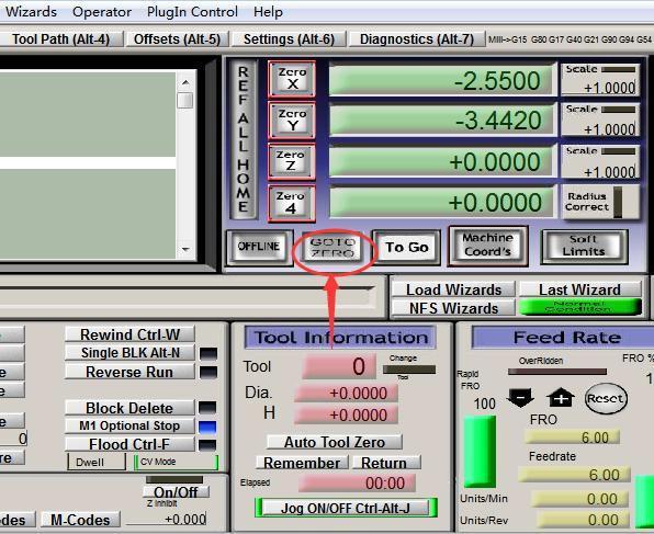
25 Offsets(Alt-5) Click Offsets(Alt-5),and change Gage Block Height to 26.5,as below: Then click Set Z or enter putton:


26 After that Click Auto Tool Zero as below: At last Click GO TO ZERO
27

28 Part 4 How to manual reset limit switch? When the software status show that the limited switch triggered as the picture attached. Then you need to reset the switches manually.


29 Please check Limit Switch triggered as below: First, find out which limited switch is triggered. Then loose the hat of the step motor as the picture below. The X Y Z axis are the same.
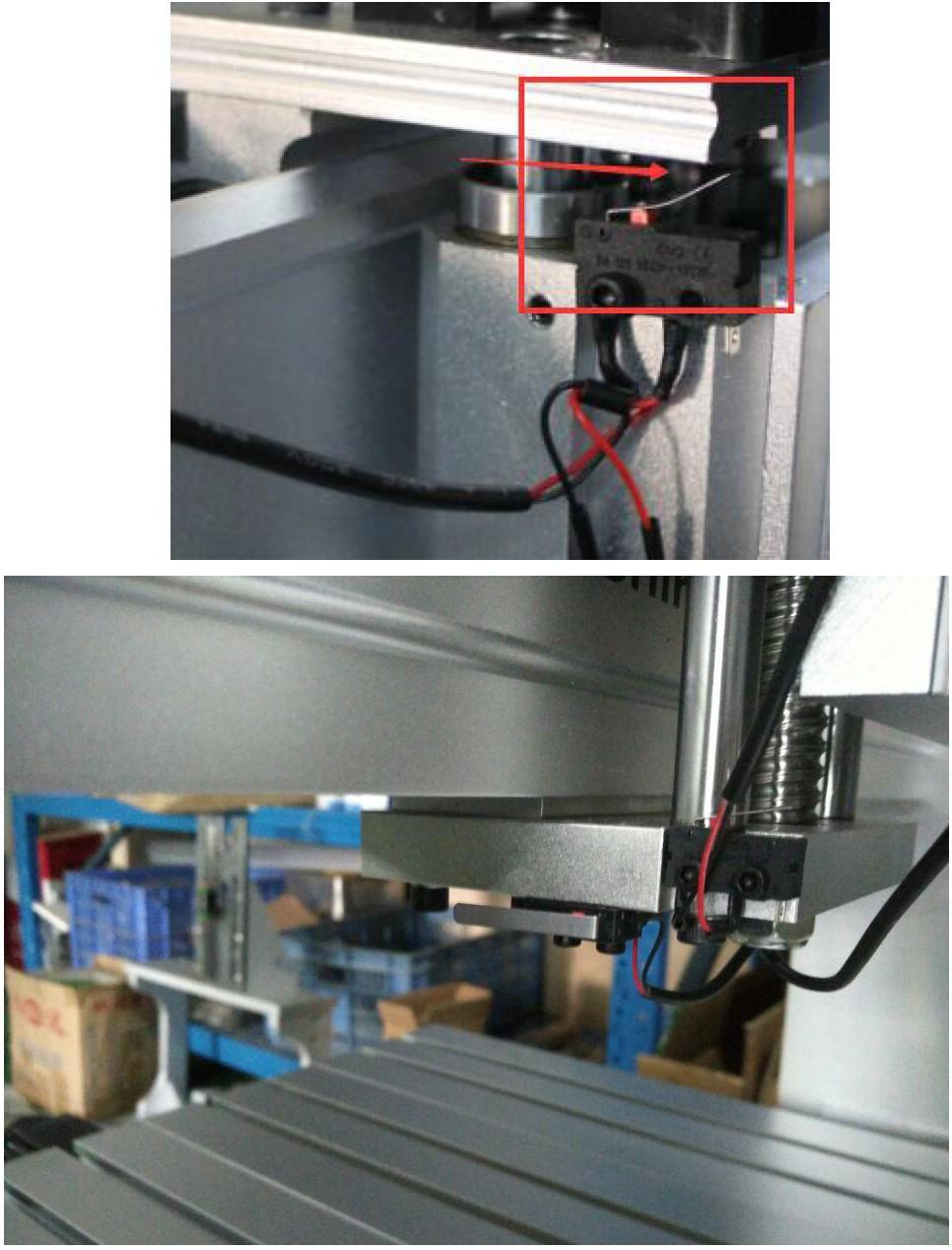
30
Move the cutting tools to the")

31 Part 5 How to setup Starting point? 1)Move the cutting tools to the starting engraving point, then Click Zero X,Zero Y,ZeroZ, Zero A as below to Reset.

32 After that,click Cycle Start as below
6040 mini Numerical Control Carving Machine manual -DSP version
 6040 mini Numerical Control Carving Machine manual -DSP version Shenzhen Scotle Technology Group Limited Chinacncnzone Address: 038-068 2F Handmade Culture Street, Phase III, Shuike Road, Bantian, Longgang,
Mach3 USB Motion Card Installation Manual
 Mach3 USB Motion Card Installation Manual Features: Fully supporting all Mach3 versions, including the Mach3 R3.043.066 version. Supporting Windows series, including Windows2000/XP/Vista/Win7/Win8/Win10.
CNC USB 6040 Engraving Machine User Manual
 CNC USB 6040 Engraving Machine User Manual Factory Address: 1st Floor, A Building, First Industrial Park, Bantian, Longgang District, Shenzhen, 518027, China Office address: 038-068 2F handmade culture
PP-BOB2-V2.0 PARALLEL PORT BREAKOUT BOARD
 PP-BOB2-V2 PARALLEL PORT BREAKOUT BOARD Document: Operation Manual Document #: T18 Document Rev: 1.0 Product: PP-BOB2-V2.0 Product Rev: 1.0 Created: October, 2015 THIS MANUAL CONTAINS INFORMATION FOR INSTALLING
Ultimate Screen Reference Guide
 MACHMOTION Ultimate Screen Reference Guide 8/11/2011 Everything you need to know to use and setup the MachMotion Ultimate Screen. MachMotion Version 1.0.2 2 P a g e Copyright 2011, MachMotion.com All rights
PraxProbe V1_0.zip is subdivided into two sets of folders; Metric and Imperial. Note that the bitmaps in each folder are identical.
 Installation Once downloaded, the installation of the macros, bitmaps and screensets is very simple. First you will need to note where is your Mach3 machine profile. For the following example, we will
Prepared by: Josh Mitchell of CORE CNCC.
 NcPod User Manual v2.0 Prepared by: Josh Mitchell of CORE CNCC www.corecnc.com Table of Contents 1. Description 2. Pinout 3. Common Connections 4. Mach Interfacing 5. Common Questions 6. Troubleshooting
PP-BOB2-V1.0 PARALLEL PORT BREAKOUT BOARD
 PP-BOB2-v1 PARALLEL PORT BREAKOUT BOARD Document: Operation Manual Document #: T17 Document Rev: 2.0 Product: PP-BOB2-v1.0 Product Rev: 1.0 Created: March, 2013 Updated: Dec, 2014 THIS MANUAL CONTAINS
imach III P3A and P3A-E CNC Control Pendant
 www.vistacnc.com - 1 - imach III P3A and P3A-E CNC Control Pendant www.vistacnc.com - 1 - imach III P3A Pendant Manual v. 3.4 www.vistacnc.com - 2 - PREFACE Any machine tool, including computer controlled
imach III P5A and P5A-E CNC Control Pendant
 www.vistacnc.com - 1 - imach III P5A and P5A-E CNC Control Pendant www.vistacnc.com - 1 - imach III P5A Pendant Manual v. 3.4.0 www.vistacnc.com - 2 - PREFACE Any machine tool, including computer controlled
User Manual. For 3rd Generation. 5 Axis Standard & Professional Breakout Board Set
 The 3 rd Generation 5 Axis Breakout Board Set User Manual For 3rd Generation 5 Axis Standard & Professional Breakout Board Set Attention: Please read the manual carefully before using the products! Email:
Ether-Mach THC Guide. Features. Ether-Mach THC Usage and Customization. Product Brief. Ether-Mach : Ethernet Motion Controller THC Guide : 1.
 Ether-Mach THC Guide Ether-Mach THC Usage and Customization Features Provides THC UP/DOWN control of the Z axis with anti-dive. Supports common THC controllers (ex, Proma THC 150) Includes free modification
Ether-Mach Mach3 Plugin Guide
 Ether-Mach Mach3 Plugin Guide Ethernet Motion Controller for Artsoft's Mach3 CNC. Features Connects over a dedicated 100 Mbps Ethernet connection. Smooth motion on 6 coordinated axes plus a spindle motor.
imach III P2-S CNC Control Pendant
 www.vistacnc.com - 1 - imach III P2-S CNC Control Pendant www.vistacnc.com - 1 - imach III P2-S Pendant Manual v. 3.3.0 www.vistacnc.com - 2 - PREFACE Any machine tool, including computer controlled machine
Turning your ideas into reality Novakon MPG Manual
 Novakon MPG Manual The E-STOP switch button on your Novakon CNC Control Pendant only provides Emergency STOP signal to Mach3 CNC application. For further protection in CNC operation, other emergency protection
COMMANDCNC UPDATING INSTRUCTIONS AND NOTES
 COMMANDCNC UPDATING INSTRUCTIONS AND NOTES REV 1.0.3 Page 1 FILE LOCATIONS FOR COMMANDCNC Root (/) --- home --- * --- Documents --- Manuals --- --- Downloads --- firmware ---
User Manual of 5Axis Breakout Board
 WWW.VALLDER.COM User Manual of 5Axis Breakout Board Safety Statement Vallder Ltd is not liable or responsible for any accidents, injuries, equipment damage, property damage, loss of money or loss of time
Manual 5 Axis-Series CNC Versions
 Manual 5 Axis-Series CNC 3040 6040 Versions Welcome Automation Technology Inc. is a supplier of motion control and CNC equipment. Featuring both the best of domestic American motion control brands, as
imach III M2 CNC Control Pendant
 www.vistacnc.com - 1 - imach III M2 CNC Control Pendant www.vistacnc.com - 1 - imach III M2 Pendant Manual v. 1.1 www.vistacnc.com - 2 - PREFACE Any machine tool, including computer controlled machine
Conversational Programming for 6000i CNC
 Conversational Programming for 6000i CNC www.anilam.com P/N 634 755-22 - Contents Section 1 - Introduction Section 2 - Conversational Mode Programming Hot Keys Programming Hot Keys... 2-1 Editing Keys...
TMC3in1 Torch & Motion Controller 3in1. Vol. 04: FAQ and Troubleshooting Guide
 TMC3in1 Torch & Motion Controller 3in1 Plasma THC - 5 Axis Breakout Board Spindle Controller Vol. 04: FAQ and Troubleshooting Guide For use with TMC3in1 Plugin Rev: 4.2.x.x Author: Randall L Ray Very Sr.
imach III P1A-S CNC Control Pendant
 www.vistacnc.com - 1 - imach III P1A-S CNC Control Pendant www.vistacnc.com - 1 - imach III P1A-S Pendant Manual v. 3.3.1 www.vistacnc.com - 2 - PREFACE Any machine tool, including computer controlled
E3 CNC Router Troubleshooting Guide
 Simple Cost Effective Designs. E3 CNC Router Troubleshooting Guide The purpose of this document is to give those new to CNC routing is a quick reference for the common issues of getting the E3 CNC router
USER S MANUAL. CNC Servo Stepper Motor Control Box CH4EV12-1 Rev. 1
 USER S MANUAL CNC Servo Stepper Motor Control Box CH4EV12-1 Rev. 1 January, 2013 i USER'S MANUAL TABLE OF CONTENTS Page # Contents 1.0 FEATURES... 1 2.0 SPECIFICATIONS... 2 3.0 SYSTEM REQUIREMENTS... 2
Apollo I Breakout Board User s Manual
 MACHMOTION Apollo I Breakout Board User s Manual 1/14/2012 Everything you need to know to set up and use your Apollo I Breakout Board. MachMotion Version 1.0.1 2 P a g e M a c h M o t i o n Copyright 2012,
Profi4 Main Board Manual
 Profi4 Main Board Manual A. Scope of application It is used to run the signal processing of the host computer ( LPT port ), with MACH 3 CNC system software, and the peripheral machine dynamic electrical.
E3 CNC Router Troubleshooting Guide
 Simple Cost Effective Designs. E3 CNC Router Troubleshooting Guide The purpose of this document is to give those new to CNC routing is a quick reference for the common issues of getting the E3 CNC router
Standard Mach4 Features included with Tangential:
 MACH4 TANGENTIAL Tangential takes place on one page: Program Run. The Tangential Profile is intended to operate Machinery equipped with a rotational axis independent of, but usually associated in, the
EC X17 - Installing guide
 EC X17 - Installing guide Features This 4 Axis CNC Stand-Alone stepper Controller ensures smooth and accurate fast motion Command and program loading is made from the EC Watch software via USB or Ethernet
2000 Series Mill / Router Operating Manual
 2000 Series Mill / Router Operating Manual 1. Introduction 1.1 Control Startup To open the control software double-click on the profile icon on the desktop. Control Icon 1.2 Overview This manual gives
Conversational Programming for 6000M, 5000M CNC
 Conversational Programming for 6000M, 5000M CNC www.anilam.com P/N 70000486F - Contents Section 1 - Introduction Section 2 - Conversational Mode Programming Hot Keys Programming Hot Keys... 2-1 Editing
Computer Aided Engineering Applications 3. Advanced Manufacturing 3.5 NC programming 3.6 Automated Manufacturing systems 3.7 Rapid prototyping
 Computer Aided Engineering Applications 3. Advanced Manufacturing 3.5 NC programming 3.6 Automated Manufacturing systems 3.7 Rapid prototyping Engi 6928 - Fall 2014 3.5 Part programming Structure of an
Geeetech Rostock mini G2 & G2s pro Quick Starter Manual
 Geeetech Rostock mini G2 & G2s pro Quick Starter Manual Please DO NOT rush to start your first printing after assembly, as this is a DIY kit, some parameters of the printer may be different from each other,
X CNC Control with Mitsubishi Drives and Servo Motors Setup Guide
 X15-350-04 CNC Control with Mitsubishi Drives and Servo Motors Setup Guide 2007 Mach Motion MachMotion X15-350-04 CNC Control with: Mitsubisi Drives Mitsubisi Motors 24V Power Supply IO6 Breakout Board
User Guide for 4 axis TB6560 driver board
 User Guide for 4 axis TB6560 driver board Product Features: Toshiba TB6560AHQ chip - High power, maximum 3.5A drive current chipset! 1-1/16 microstep setting - Higher accuracy and smoother operation than
OKUMA MACHINING CENTER OPERATORS GUIDE OSP P200M THiNC
 OKUMA MACHINING CENTER OPERATORS GUIDE OSP P200M THiNC OSP P200 Mill Training Rev1 1 OKUMA MACHINING CENTER OPERATORS GUIDE Scope 4 Section 1 Guide to Controls on Operation Panels 5 Section 2 Manual Tool
User Guide for 3 axis TB6560 driver boar d
 User Guide for 3 axis TB6560 driver boar d Product Features: Toshiba TB6560AHQ chip - High power, maximum 3.5A drive current chipset! 1-1/16 microstep setting - Higher accuracy and smoother operation than
EC X17 - CNC Ethernet Stepper Controller
 EC X17 - CNC Ethernet Stepper Controller Features This 4 Axis CNC Stand-Alone stepper Controller ensures smooth and accurate fast motion Command and program loading is made from the EC Watch software via
User Guide for 4 axis TB6560 driver board. *Important Note*: Please strictly follow the setting photos for configuration
 User Guide for 4 axis TB6560 driver board Settings of MACH3 *Important Note*: Please strictly follow the setting photos for configuration in Mach3! Fig.1 Open MACH3 software, select mach3mill, and then
4-axis parallel port encoder interface For Mach2/3 CNC control software. Closed loop operation for Servo and Stepper systems. General User s Guide
 Sound Logic Encoder Interface 4-axis parallel port encoder interface For Mach2/3 CNC control software Closed loop operation for Servo and Stepper systems General User s Guide Sound Logic James Cullins
CHANGZHOU WANTAI ELECTRICAL APPLIANCE CO., LTD. User Guide for 3 axis TB6560 driver board
 CHANGZHOU WANTAI ELECTRICAL APPLIANCE CO., LTD Product Features: User Guide for 3 axis TB6560 driver board Toshiba TB6560AHQ chip - High power, maximum 3.5A drive current chipset 1-1/16 microstep setting
Stepper Drive Setup Guide
 MACHMOTION Stepper Drive Setup Guide 1/21/2011 Everything you need to know to connect your stepper motors to the MachMotion stepper drives. MachMotion Version 1.0.1 2 P a g e Copyright 2011, MachMotion.com
OEM Buttons - MachCustomizeWiki
 Page 1 of 8 OEM Buttons From MachCustomizeWiki This list gives the codes to be used in calls of DoOEMButton. If you are using a version of Mach3 prior to 1.90 then to use bunttons in this list that are
User manual CCV Mini (Android)
") TABLE OF CONTENTS 1. PREPARING THE CCV MINI FOR USE... 4 1.1. List of items supplied... 4 1.2. Environmental factors that may affect the equipment s operation... 4 1.3. Step 1 - Charge the card reader...
TABLE OF CONTENTS 1. PREPARING THE CCV MINI FOR USE... 4 1.1. List of items supplied... 4 1.2. Environmental factors that may affect the equipment s operation... 4 1.3. Step 1 - Charge the card reader...
DMSF PCB ROUTER OPERATION GUIDE
 DMSF PCB ROUTER OPERATION GUIDE A. Preparation of NC files for PCB Router The input to the PCB router is NC file that contain commands and data being readable by the controller of the router s controller.
FlashCut CNC / Precix Router User s Guide v1.2 Brett Ian Balogh 31.October, Ensure the computer is plugged in. Do not plug the spindle in yet.
 FlashCut CNC / Precix Router User s Guide v1.2 Brett Ian Balogh 31.October, 2011 1. Ensure the computer is plugged in. Do not plug the spindle in yet. 2. Start the computer by pressing the on/off button
Stepper Systems. Chapter Four. Features Machine Specifications And Bid Proposals. Catalog Numbers
 Stepper Systems Features Machine Specifications And Bid Proposals Chapter Four Stepper 11x13: Stepper 21x19: Stepper 21x29: Stepper 21x39: Stepper 31x33: Stepper 49x41: Catalog Numbers HX33SBME01201505
HY-TB5 CNC Series Manual five axis
 HY-TB5 CNC Series Manual ------ five axis Thank you for choosing our products better and faster for you to use NC products, please read this manual, make sure the pump is started before the water-cooled
EGX-400/600 ADA Hardware and Software Setup Guide v1.0
 EGX-400/600 ADA Hardware and Software Setup Guide v1.0 EGX-400/600 ADA Hardware and Software Setup Guide This guide covers configuration of the Raster TM Braille Dot cutter and Character cutter. NOTES:
Running a Job on the Large Mill
 Running a Job on the Large Mill Digital Media Tutorial Written by Trevor Williams Turning On the Machine Flip the breaker switch on the front right of the lower part of the controller box to the ON position.
Panther. CNC Cape for Beaglebone Black. Users Manual. Version 1.2. Warning!
 Panther CNC Cape for Beaglebone Black Users Manual Version 1.2 Warning! The CNC Cape is intended to build a CNC control. As a CNC control is an electronic device which includes working with high voltages
Ballbar QC20-W - Analysis
 Haas Technical Documentation Ballbar QC20-W - Analysis Applies to machines built from: January, 2016 Scan code to get the latest version of this document Translation Available Ballbar QC20-W - Analysis
Volume BADOG CNC REVISION DOCUMENTS. Suppliment InfoSeries : Configuration of Ports for Badog CAD. Badog CNC Machine Extras
 Volume 7 BADOG CNC REVISION DOCUMENTS Suppliment InfoSeries : Configuration of Ports for Badog CAD Badog CNC Machine Extras X2, X3, FATDOG, PUP AND UNITS Badog CNC Machine Extras Badog CNC 2010 1Rue Aliénor
HDS Series Quick Start Guide.
 Techno-Osai Start Up Sequence HDS Series Quick Turn the Main power switch to the ON Position. 220 volts should have been attached to this switch by an electrician. Power On Button. Computer power ON. The
Motion Control Interface. Instruction Manual
 HyCNC-6L(6 Axis)USB Motion Control Interface Instruction Manual HyTechWorks 2013 FW 2.0.0.3 Cautions HyTechWorks provides its products and services as it is. HyTechworks accepts no responsibility for performance
Hardware Installation Manual MX Axis Stepper Drive with Breakout Board & I/O s
 Hardware Installation Manual MX3660 3-Axis Stepper Drive with Breakout Board & I/O s Version 1.0 11 / 2013 Hardware Manual for MX3660 3-Axis Stepper Drive with Breakout Board & I/O s ii Notice Read this
IO3-R2 BREAKOUT BOARD
 IO3-R2 BREAKOUT BOARD DESCRIPTION Breakout board IO3-R2 (Revision R2) has digital buffer for STEP/DIR/ENA command signals and as such it is particularly suitable for the connection up to 4 microstep drives
CNC Shield Guide V
 CNC Shield Guide V1.0 12 2018 Maker Group Global LLC 2018 Safety Statement The author of this document is not liable or responsible for any accidents, injuries, equipment damage, property damage, loss
Calibration Guide. Software Interface Introduction. In Control Pad Tab. Add: add print file. Setting: set parameters and calibrate
 Calibration Guide Software Interface Introduction In Control Pad Tab Add: add print file Setting: set parameters and calibrate Online: online / offline switch Home: carriage goes to home position Down
Manual 5 Axis CNC Interface Breakout Board Model#-DB25-1R5AM
 Manual 5 Axis CNC Interface Breakout Board Read this manual carefully before making connections to the board. Store this manual away for further reference. Safety Notes: The electronics of the control
Geeetech Duplicator 5 3D printer. User Manual
 Geeetech Duplicator 5 3D printer User Manual Contents Safety Instructions... 4 1.Software Resources... 5 1.1 Repetier-Host... 5 1.2 Driver... 5 1.3 Arduino IDE... 6 2.Connect the Printer... 6 3.Printer
USER S MANUAL. CNC Stepper Motor Control Box CS3EA4-1 Rev. 1
 USER S MANUAL CNC Stepper Motor Control Box CS3EA4-1 Rev. 1 April, 2012 USER'S MANUAL TABLE OF CONTENTS Page # Contents 1.0 FEATURES... 2 2.0 SPECIFICATIONS... 3 3.0 SYSTEM REQUIREMENTS... 3 4.0 WARNING...
Control Box Setup - PRSalpha
 888-680-4466 ShopBotTools.com Control Box Setup - PRSalpha Copyright 2016 ShopBot Tools, Inc. page 1 Copyright 2016 ShopBot Tools, Inc. page 2 Parts List: Hooking Up a PRSalpha Gantry Tool Powering the
CommandCNC 1.1 Release Notes
 CommandCNC 1.1 Release Notes What's new in 1.1 Auto-Set support for DTHC...2 Fixture Offsets...7 User Interface Rework...11 Output buttons can now be customized... 12 Support for two more axes...14 New
Ladybird Project - Vacuum Mould
 - Vacuum Mould Prerequisite Mould drawn and saved as STL file from Solidworks Focus of the Lesson On completion of this exercise you will have completed: Opening STL file Setting Machining Constraints
VISY-X. Technical Documentation. Subsequent installation of VISY-Density. Edition: Version: 2 Art. No.:
 Technical Documentation VISY-X Subsequent installation of VISY-Density Edition: 2016-08 Version: 2 Art. No.: 350063 FAFNIR GmbH Schnackenburgallee 149 c 22525 Hamburg Tel.: +49 / 40 / 39 82 07 0 Fax: +49
Mach4 Industrial Mill Operations Guide
 Mach4 Industrial Mill Operations Guide 1 Copyright 2014 Newfangled Solutions, Artsoft USA, All Rights Reserved The following are registered trademarks of Microsoft Corporation: Microsoft, Windows. Any
CPU5A Economy Series USBCNC software included. Features
 CPU5A Economy Series 125 KHz step frequency, 4 axes. Card size 100x100mm. USB 2.0 connection. 100 Mbit Ethernet connection (*). 5 Status LED's. Full 4 axes interpolation (*). 7 Standard CNC outputs. 0-10V
527F CNC. Retrofit controller for machines made by Fadal Machining Centers. Installation and set-up manual Calmotion LLC
 527F CNC Retrofit controller for machines made by Fadal Machining Centers Installation and set-up manual 2008-2018 Calmotion LLC Calmotion LLC 7536 San Fernando Road Sun Valley, CA 91352 www.calmotion.com
BURNER BREAKER USER MANUAL
 BURNER BREAKER USER MANUAL www.susteen.com CONTACT Susteen Inc. 18818 E Teller Ave., Suite 102 Irvine, CA 92612 sales@susteen.com Tel: + 1 949 341 0007 TABLE OF CONTENTS Introduction i Setting up USB Camera
Manual. Model#-DB25M-3R6A. 6 Axis CNC Interface Breakout Board. Lastest update : Feb Store this manual away for further reference.
 Manual 6 Axis CNC Interface Breakout Board Model#-DB25M-3R6A Lastest update : Feb 2016 Read this manual carefully before making connections to the board. Store this manual away for further reference. Safety
Apollo III INSTALLATION MANUAL
 Apollo III INSTALLATION MANUAL 2 P a g e 5/1/14 N0112 This manual covers the setup and configuration of the Apollo III motion controller connected to the control using Mach3. Formatting Overview: Menus,
Breakoutboard for ESS Smoothstepper
 Breakoutboard for ESS Smoothstepper Operation Manual All rights to these operating instructions remain with cnc-technics. Texts, information and illustrations of these operating instructions may not be
Challenge Is The Game LEVEL 10M ADVANCED GAMING SOFTWARE USER GUIDE. Tt esports LEVEL 10M ADVANCED Gaming Software User Guide
 Challenge Is The Game LEVEL 10M ADVANCED GAMING SOFTWARE USER GUIDE 01 CONTENTS Challenge Is The Game PAGE 04 Main Interface PAGE 05 PAGE 13 PAGE 14 PAGE 20 PAGE 22 PAGE 23 Key Assignment Macro Interface
527F CNC. Retrofit controller for machines made by Fadal Machining Centers. Installation and set-up manual Calmotion LLC
 527F CNC Retrofit controller for machines made by Fadal Machining Centers Installation and set-up manual 2008-2018 Calmotion LLC Calmotion LLC 7536 San Fernando Road Sun Valley, CA 91352 www.calmotion.com
CONUCON Software. User Guide. for Linion, Dora and Fresadora. Dezember 2018 CONUCON Software v
 CONUCON Software User Guide for Linion, Dora and Fresadora Dezember 2018 CONUCON Software v181216 1 Contents 1.First Steps...2 Installing Drivers...2 Connecting...4 Graphical User Interface...4 Safety
EASY MACH 3 SETUP & USER GUIDE
 EASY 4 STEPS SETUP: 1. Insert 2AA batteries into MPG 2. Plug USB to computer 3. Copy XHC-ShuttlePro.dll into C:\Mach3\PlugIns 4. Start Mach3 and MPG can be used. INSTRUCTION TO SET BUTTON To set up button
Novusun Controller Wiring and MACH3 Software Setup
 Novusun Controller Wiring and MACH3 Software Setup V1.0 01 2019 Open Source Mechatronics LTD 2019 Safety Statement The author of this document is not liable or responsible for any accidents, injuries,
9000 CNC 9000 CNC: THE NEW STANDARD OF CONTROL. INTUITIVE EFFICIENT PRODUCTIVE
 3D Solid Model Graphics Solid Model with Tool Path Overlay 9000 CNC 9000 CNC: THE NEW STANDARD OF CONTROL. At Milltronics we are constantly refining our controls to simplify operation, shorten setup times
GSK218M Milling Machine CNC System
 GSK218M Milling Machine CNC System GSK218M is widespread CNC system (matched with machining center and general milling machine) employed with 32-bit high performance CPU and super-large-scale programmable
3 axes Cnc driver kit User manual
 3 axes Cnc driver kit User manual Hardware Revision: 5.4.2 Firmware Revision: 5.0 User Manual Revision: 0.3 Main features Congratulations for buying 3 axes Cnc driver kit. The board you just bought, either
imach III P4-S and P4-SE CNC Control Pendant
 www.vistacnc.com - 1 - imach III P4-S and P4-SE CNC Control Pendant www.vistacnc.com - 1 - imach III P4-S Pendant Manual v. 4.0 www.vistacnc.com - 2 - PREFACE Any machine tool, including computer controlled
Using the PMDX-125/126 Mach3 Plug-In Ver
 Unless otherwise stated, this manual uses the term PMDX-125 generically to refer to both the PMDX-125 and PMDX-126 boards. The PMDX-125 Plug-In will work with either a PMDX-125 or PMDX-126 board. 1.0 Terms
Geeetech Aluminum Prusa I3. User Manual
 Geeetech Aluminum Prusa I3 User Manual 1 Safety Instructions Building the printer will require a certain amount of physical dexterity, common sense and a thorough understanding of what you are doing. We
Stepper. Manuals about stepper drives. Stepper Drive Wiring Diagram - Apollo Stepper Drive Setup Guide
 Stepper Manuals about stepper drives Stepper Drive Wiring Diagram - Apollo Stepper Drive Setup Guide Stepper Drive Wiring Diagram - Apollo Cont rol Connect or Signal PUL+ PUL DIR+ DIR EN+ EN Color Brown/White
RazorGage Inkjet Printer Changing the Character Aspect Ratio & Spacing
 RazorGage Inkjet Printer Changing the Character Aspect Ratio & Spacing RazorOptimal Software From the Main Screen Press Diagnostics From the Diagnostics Screen press Evolution Inkjet Autolist Software
Datasheet MX Axis Stepper Drive with Breakout Board & I/O s. Version1.0
 Datasheet MX3660 3-Axis Stepper Drive with Breakout Board & I/O s Version1.0 1. Features Power up to 3 stepper motors of NEMA 17, 23, 24, or 34 Sophisticated stepper motor control based on latest DSP technology
Setting up the Roland EGX-300 and EngraveLab to cut IkonicsMetal
 Setting up the Roland EGX-300 and EngraveLab to cut IkonicsMetal Setting Up the Roland EGX-300: 1. Power unit off 2. Remove any existing tools and install the 11/64 solid collet to the bottom of the spindle
This document shows you how to set the parameters for the ModuleWorks Material Removal Simulation.
 Table of Contents Introduction:... 3 Select Profile:... 4 Tool Table - Create Tool(s)... 5 Tool properties:... 5 Tool Color R/G/B:... 6 Simulation Configurations - create stock... 7 What if plugin is greyed
DeskCNC setup and operation manual
 DeskCNC setup and operation manual This document explains how to install, setup and cut foam shapes using DeskCNC 4 axis foam cutting software. The document will go through a step by step process of how
Computer Numerical Control for Windows Version 1.2. User s Guide
 Computer Numerical Control for Windows Version 1.2 User s Guide 1998 FlashCut CNC, Inc. 1263 El Camino Real, Suite W, Menlo Park, CA 94025 Phone (650) 853-1444 Fax (650) 853-1405 www.flashcutcnc.com Table
CNC4X35A 4 axis Stepper Motor Control Board
 CNC4X35A 4 axis Stepper Motor Control Board Just connect bipolar stepper motors, power and a parallel port signal source CNC4X35A 4 axis Stepper Motor Control Board Specs: Designed for easy construction/retrofit
Panther. CNC Cape for Beaglebone Black. Users Manual. Version 1.1. Warning!
 Panther CNC Cape for Beaglebone Black Users Manual Version 1.1 Warning! The CNC Cape is intended to build a CNC control. As a CNC control is an electronic device which includes working with high voltages
Introduction. Prerequisites. Ballbar - QC20-W - Analysis LAST UPDATED: 12/01/2018
 Ballbar - QC20-W - Analysis LAST UPDATED: 12/01/2018 Ballbar - QC20-W - Analysis Introduction This procedure tells you how to do a Renishaw QC20-W ballbar analysis. The QC20-W BallBar uses a Bluetooth
Operation Manual (B) KVR-2418 (24L) Fanuc OiMD CNC. KENT INDUSTRIAL (USA) INC Edinger Ave., Tustin, CA 92780
 KVR-2418 (24L) Fanuc OiMD CNC. KENT INDUSTRIAL (USA) INC Edinger Ave., Tustin, CA 92780") Operation Manual (B) KVR-2418 (24L) Fanuc OiMD CNC KENT INDUSTRIAL (USA) INC. 1231 Edinger Ave., Tustin, CA 92780 Tel: (714) 258-8526 Fax: (714) 258-8530 Internet: WWW.KENTUSA.COM KENT USA THE WAY TO AFFORDABLE
Operation Manual (B) KVR-2418 (24L) Fanuc OiMD CNC KENT INDUSTRIAL (USA) INC. 1231 Edinger Ave., Tustin, CA 92780 Tel: (714) 258-8526 Fax: (714) 258-8530 Internet: WWW.KENTUSA.COM KENT USA THE WAY TO AFFORDABLE
DaVinci Systems. Features Machine Specifications And Bid Proposals
 DaVinci Systems Features Machine Specifications And Bid Proposals Chapter Three Catalog Numbers DaVinci 8x8: HL33SBME242500 DaVinci 8x10: HL33SBME242510 DaVinci 10x12: HL33SBME242512 DaVinci 14x19: HX33VBME242201
Trucut SeriesOne/XT. Operators Manual. SeriesOne and XT machines running Mach4 Software
 Trucut SeriesOne/XT Operators Manual SeriesOne and XT machines running Mach4 Software Table Of Contents Overview 1 1 Mach4 User Interface 2 1.1 Primary Function Screens 2 1.1.1 Program Run 3 1.1.2 Diagnostics
Mach4 CNC Controller Software Installation and Configuration Guide Version 1.0
 Mach4 CNC Controller Software Installation and Configuration Guide Version 1.0 1 Of 27 Copyright 2014 Newfangled Solutions, Artsoft USA, All Rights Reserved The following are registered trademarks of Microsoft
Z Spindle. Revision 1.2. Copyright Newing-Hall, Inc Monroe Street. Toledo, Ohio, NH Part # Last Update July 2003
 Z Spindle Revision 1.2 Copyright 1998-1999 Newing-Hall, Inc. 2019 Monroe Street Toledo, Ohio, 43624 NH Part #2511013 Last Update July 2003 This manual is subject to change without notice. Table Of Contents
Our thanks go to: Puppy Linux, RTAI, EMC, axis, all the kernel developers and big mama thornton.
 CoolCNC Linux First Steps This manual is a step by step introduction for the installation of the CoolCNC Linux Live CD. Its intent is to lead to a better understanding of the current processes. This document