Service Manual. Zenis POS Series
|
|
|
- Erika Lorin Scott
- 6 years ago
- Views:
Transcription

1 Service Manual Zenis POS Series Version 1.0 Copyright Fametech Inc. (TYSSO) 2010 i
2 Table of Contents I Part List A. Explode... 1 B. Cables & Connectors... 3 II Flash/Update BIOS... 7 III System Disassembly A. Separate Front Panel from Base B. Disassemble Panel Kit Table of Figures Figure 1 Explode of the System... 1 Figure 2 Cables... 3 Figure 3 Mainboard Layout... 4 Figure 4 I/O Board Layout... 5 Figure 5 Inverter Layout... 5 Figure 6 Touch Control Board Layout... 5 ii
3 I Part List A. Explode Figure 1 Explode of the System 1
4 No. Part No. Description Price(USD) 1 JP-POS-3000-FRONT-COVER-W Front Cover(White) 12 2 CP-CBL-POS-7000-LED-PW Power Indicator 1 3 JP-POS-5050-RUBBER Touch Panel Rubber 3 4 BP-PART-CUBIC-QF117V1 Inverter 12 5 LC-LG-LM150X08 LCD Panel KP-POS-5700-LCD LCD Panel Chassis 10 7 LT-HT-150F-5RA-G01N-18R-200FH Touch Panel 50 8 KP-POS BRKT Power Switch Bracket 3 9 NS-POS-5000-HIT Speakers 5 10 KP-POS-5715-PWR-SW-BRKT Power Switch Bracket 3 11 CP-CBL-POS-5700-SW-B15CM Power Switch 2 12 BP-PART-THPCBA-COMBO-R5W-3100C Touch Control Board BP-PCBA-POS-5700-CONN PS2 Board BP-PART-POS-3000-MB-PCBA Mainboard KP-POS-5715-MB-COVER Mainboard Cover 8 16 KP-POS-6000-HD-HOLDER HDD Holder 2 17 BP-PART-SATA-2.5HDD-80G-5400 HDD JP-POS-3000-MSR-RIGHT-Cover-W MSR Cover BP-SEMI-POS-3000-MSR-KP-W MSR Kit JP-POS-3000-REAR-COVER-W Rear Cover 15 *19-1 JP-POS-3000-ANTENNA-PLUG-W Plug JP-POS-3000-HD-COVER-W HDD Cover 3 21 BP-SEMI-POS-3000-HINGE-HOLDER-W Hinge Holder JP-POS-3000-HINGE-COVER-W Hinge Rear Cover 2 23 KP-POS-3000-BASE-W Aluminum Base KP-POS-3000-BASE-HOLDER-W Base Holder 3 25 JP-POS-3000-BASE-COVER-W Base Cover 3 26 JP-POS-3000-HINGE-SWIVEL-W Hinge Swivel 3 27 DP-PWRC-EA11003A-ED Power Adapter KP-POS-3000-PWR-BRKT Power Adapter Holder 6 * If the antenna is equipped, the plug will not be included in the system. 2
5 B. Cables & Connectors Figure 2 Cables 3


6 Figure 3 Mainboard Layout 4


7 Figure 4 I/O Board Layout Figure 5 Inverter Layout Figure 6 Touch Control Board Layout 5
8 No. Part No. Description Price(USD) 1 CP-CBL-POS-SATA-HDD HDD Cable 5 2 CP-CBL-POS-5000-TH-USB Touch Cable 2 3 CP-CBL-POS-5700-LVDS-B24cm LVDS Cable 4 4 CP-CBL-POS-5700FS-LED-PW Power Indicator 1 5 CP-CBL-POS-5700-SW-B15CM Power Switch 2 6 NS-POS-5000-HIT Speakers 5 7 CP-CBL-POS-5700-MMSR-B17cm MSR Cable 3 8 CP-CBL-POS-7000-INT Inverter Cable 2 9 CP-CBL-POS-5700-MB-IO-B10 I/O Board Cable 2 Part No. Description Price(USD) BP-PART-POS-5000-HEATSINK CPU heat dissipation fin 15 BP-PART-SYS FAN-DFB500912M POS System Fan DFB500912M 5 BP-PART-DDR2-667/800-1GB DDRII RAM 1GB, DDR2-667/ Pin 35 BP-PART-DDR2-667/800-2GB DDRII RAM 2GB, DDR2-667/ Pin 60 6

9 II Flash/Update BIOS a. Download GSE30406 folder to a bootable USB-FDD or USB drive. b. Disconnect the HDD cable from the hard drive disk. Connected an external USB-FDD or USB drive to POS-3000, and enter the DOS system as the figure below. c. As C:\> appears, enter dir and press the <Enter> key to enter the GSE30406 menu as the figure below. 7

10 d. Enter cd GSE30406 and then press the <Enter> key. The content of GSE30406 folder will show on the monitor as the figure below. e. Enter dir and then press the <ENTER> key. View the batch file in the GSE30486 folder. 8

11 f. Enter the name of the batch folder and then press the <ENTER> key to progress BIOS UPDATE. g. BIOS UPDATE in progress 9


12 III System Disassembly A. Separate Front Panel from Base 1. Tilt the LCD panel to the horizontal level and unplug the power cord. 2. Remove the hinge holder covers according to the direction of the arrows. 3. Lossen the 5 screws to remove the base holder from the panel 10


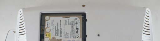


13 B. Disassemble Panel Kit 4. Loosen the screw to remove the HDD cover. 5. Loosen the screw x 8 to remove the back cover. 6. Loosen the spacer and disconnect the HDD cable. 11


14 7. Loosen the screw x 9 to remove the bracket. 8. Disconnect the HDD cable. 9. Loosen the screw x 2 and MSR cable to remove the MSR kit. 12


15 10. Loosen the screw x 2 and disconnect the 3 cables to remove the invertor. 11. Loosen the screw x 2 and disconnect the cable to remove the SW plate. 12. Pull the hooks to remove the Connect board 13


16 13. Loosen the screw x 2 and disconnect the touch USB cable to remove the touch control board. 14. Disconnect the LVDS cable. 15. Disconnect the LED cable 14


17 16. Loosen the spacer x 10 on the I/O bracket. 17. Loosen the screw x 8 to remove the speakers. 18. Loosen the screw x 5 to remove the mainboard from the LCD panel holder. 15


18 19. Remove the RAM. 20. Turn over the mainboard and loose the 5 screws 21. Remove the fan cable and remove the heat sink. 16


19 22. Tear the black tape and disconnect the LVDS cable Loosen the screw x 3 to remove the I/O bracket from the LCD panel holder. 17


20 24. Loosen the screw x 7 to remove the LCD panel holder. 25. Loosen the screw x 4 to remove the LCD panel holder. 26. Remove the front cover of the touch panel. 18


21 Remove the rubber.


22 C. Disassemble Base Kit 28. Turn over the base and loosen the screw x 4 to remove the power adaptor. 29. Remove the hinge swivels. 20


23 30. Loosen the screw x 8 on both sides to remove the hinge holder. 21
Disassembly Procedure
 Chapter 2 Disassembly Procedure Please follow the information provided in this section to perform the complete disassembly procedure of the notebook. Be sure to use proper tools described before. A SUS
Disassembly Procedure
 Chapter 2 Disassembly Procedure Please follow the information provided in this section to perform the complete disassembly procedure of the Eee PC 1201HA. Be sure to use proper tools described before.
Le Disassembly. Required Tools Disassembly Instructions Reassembly Instructions
 Le Div@ Disassembly Required Tools Disassembly Instructions Reassembly Instructions Required Tools All Le Div@ maintenance procedures can be performed using the following tools: Tweezers Small flat-head
Disassembly Procedure
 Chapter 3 Disassembly Procedure Please follow the information provided in this section to perform the complete disassembly procedure of the notebook. Be sure to use proper tools described before. A SUS
ASUS A2000 Series Notebook consists of various modules. This chapter
 Chapter 2 Disassembly Procedure Please follow the information provided in this section to perform the complete disassembly procedure of the notebook. Be sure to use proper tools described before. ASUS
Disassembly Procedure
 Chapter 2 Disassembly Procedure Please follow the information provided in this section to perform the complete disassembly procedure of the notebook. Be sure to use proper tools described before. SUS A7T
Disassembly Procedure
 Chapter 2 Disassembly Procedure Please follow the information provided in this section to perform the complete disassembly procedure of the notebook. Be sure to use proper tools described before. A SUS
WEASEL N/B MAINTENANCE
 2. System Assembly & Disassembly 2.1 System View 2.1.1 Front View ❶ Microphone Connector ❷ Audio Input Connector ❸ Audio Output Connector ❹ Top Cover Latch ❹ ❶ ❸ ❷ 2.1.2 Left-Side View ❶ VGA Port ❷ S-Video
8806 Series. 15 Multi-functional Touch Panel PC. Quick Reference Guide
 8806 Series 15 Multi-functional Touch Panel PC Quick Reference Guide 1st Ed 10 July, 2009 8806 Contents 1. Getting Started...3 1.1 Safety Precautions...3 1.2 Packing List...3 1.3 System Specifications...4
Disassembly Procedure
 Chapter 3 Disassembly Procedure Please follow the information provided in this section to perform the complete disassembly procedure of the notebook. Be sure to use proper tools described before. A SUS
Product End-of-Life Disassembly Instructions
 Product End-of-Life Disassembly Instructions Product Category: Personal Computers Marketing Name / Model [List multiple models if applicable.] HP Compaq 8200 Elite USDT Business PC Name / Model #2 Name
FIELD REPLACEABLE UNIT DOCUMENTATION
 Satellite TM 1700 Series GENERAL INFORMATION Tools Required for Proper Disassembly and Reassembly: 1. Phillips Screwdriver (Size 1) 2. Flat head screwdriver (5mm) 3. Hex driver (5mm) 4. Case Separator
ARL 970/ ARL970-B User Reference Manual
 ARL 970/ ARL970-B User Reference Manual Specifications Model No ARL970 ARL970-B CPU Intel Core i5-2510e, 3M Cache, 2.50GHz Processors (Option: Intel Core i7-2710qe, 6M Cache, 2.10 GHz) Chipset Intel QM77
USER MANUAL VERSION V1.0 AUG MiniPOS Hardware System
 USER MANUAL VERSION V1.0 AUG 2010 MiniPOS Hardware System Copyright 2010 August All Rights Reserved Manual Version 1.0 Part Number: 3LMPPA530110 The information contained in this document is subject to
EVGA assumes you have purchased all necessary parts needed to allow for proper system functionality.
 Before You Begin Parts NOT in the Kit This kit contains all the hardware necessary to install and connect your new EVGA e-7050/610i GPU motherboard with integrated GeForce graphics processing. However,
ARL 945/ ARL945-B User Reference Manual
 ARL 945/ ARL945-B User Reference Manual Specifications Model No ARL945 ARL945-B CPU Intel Core 2 Duo T7500, 2.2GHz Processors (Option: Intel Core 2 Duo T9400, 2.53 GHz) Chipset Intel Gm45 Chipset + ICH9M
Disassembly Procedure
 Chapter 3 Disassembly Procedure Please follow the information provided in this section to perform the complete disassembly procedure of the notebook. Be sure to use proper tools described before. ASUS
Disassembly Manual Version 1.1
 EasyNote K5 Disassembly Manual Version 1.1 Required Tools Disassembly Instructions DIP Switch Setting Reassembly Instructions Required Tools ll EasyNote K5 maintenance procedures can be performed using
TEOS Hardware System TEOS 8416 / TEOS 1016/ TEOS1216
 TEOS Hardware System TEOS 8416 / TEOS 1016/ TEOS1216 Revision v1.1 November 2011 Copyright 2009~2011 All Rights Reserved Manual Version 1.1 The information contained in this document is subject to change
How-To: Disassembly Instructions UD3
 How-To: Disassembly Instructions UD3 19.04.2018 Contents Disassembly Instructions for UD3... 3 Tools and Equipment... 4 Preparation... 5 DVI VGA Adapter... 5 Base Stand... 6 Connectivity Bar (if available)...
Upgrade & Replacement
 Chapter 5 Upgrade & Replacement Follow the individual procedures in this chapter to perform the notebook s upgrade and replacement of various major components. A sus A6000U Series Notebook is a 2 spindles
KN1Series Notebook consists of various modules. This chapter describes
 Chapter 2 Disassembly Procedure Please follow the information provided in this section to perform the complete disassembly procedure of the notebook. Be sure to use proper tools described before. KNSeries
ARL992/ ARL992-B User Reference Manual
 ARL992/ ARL992-B User Reference Manual Specifications Model No ARL992 ARL992-B CPU Intel Core i5-7440eq, 2.90GHz Processors Option: Intel Core i7-7820eq, 3.0 GHz Chipset Intel 7th Gen. Core i5 /i7 processors
Product End-of-Life Disassembly Instructions Product Category: Personal Computers
 Product End-of-Life Disassembly Instructions Product Category: Personal Computers Marketing Name / Model [List multiple models if applicable.] OMEN X by HP Desktop PC 900 Purpose: The document is intended
TravelMate 280 Exploded Diagram. www MK-Electronic de. Chapter 6 125
 TravelMate 280 Exploded Diagram Chapter 6 125 Cables LCD COAXIAL CABLE 15 XGA CABLE LCD COAXIAL 15 XGA 7 LAUNCH BOARD CABLE CABLE LAUNCH BOARD S50 INVERTER CABLE CABLE LED & INVERTER POWER CORD 125V 3PIN
FIELD REPLACEABLE UNIT DOCUMENTATION. Satellite TM. A20 Series GENERAL INFORMATION. Tools Required for Proper Disassembly and Reassembly:
 GENERAL INFORMATION Tools Required for Proper Disassembly and Reassembly: 1. Phillips Screwdriver (Size 0&1) 2. 4mm Flat head Screwdriver 3. Case Separator 4. ESD Wrist Strap 5. ESD mats 6. Tweezers Before
Easy Note Alpha Disassembly. Required Tools Disassembly Instructions Reassembly Instructions
 Easy Note Alpha Disassembly Required Tools Disassembly Instructions Reassembly Instructions Required Tools All Easy Note Alpha maintenance procedures can be performed using the following tools: Tweezers
4. Screw the Stand-offs onto the holes of the motherboard tray. 2. Slide the top cover backward slowly and lift it up to remove it.
 LC03 / LC03V 1. Unscrew the screw on the rear part of the top cover. 2. Slide the top cover backward slowly and lift it up to remove it. 3. Unscrew two screws attached on the motherboard tray to remove
Illustrated Parts Breakdown
 6 Illustrated Parts Breakdown! Exploded View! Field Replaceable Units! Cable List! Processors! Memory Expansion! Hard Disk Drives! Tape Drives! RAID Controllers and Cache! Network Option Boards! SCSI Terminators
AMI200 Series User Manual
 AMI200 Series User Manual 2012 August V4.0 Copyright 2010 IBASE Technology INC. All Rights Reserved. No part of this manual, including the products and software described in it, may be reproduced, transmitted,
XT-3815/3915IR Fanfree LCD Touch Terminal Quick Installation Guide
 XT-3815/3915IR Fanfree LCD Touch Terminal Quick Installation Guide Package Contents XT-3815 or XT-3915IR terminal with base stand x 1 60W power adaptor x 1 Power cord x 1 Screw for IO cable cover x 2 Quick
EVO-TP Hardware System
 User Manual Revision v1.3 February 2010 EVO-TP Hardware System Copyright 2009 February All Rights Reserved Manual Version 1.1 Part Number: The information contained in this document is subject to change
ARP 690 User Reference Manual
 ARP 690 User Reference Manual Specifications Model No Motherboard Slots Display Drive bay VGA KB/MS Power Supply Construction Speaker Dimension Weight Carrying Case ARP690 Support ATX Motherboard Offer
User Manual Version V1.1 March Elios Point-of-Sale Hardware System
 User Manual Version V1.1 March 2010 Elios Point-of-Sale Hardware System Copyright 2009~2010 All Rights Reserved Manual Version 1.1 The information contained in this document is subject to change without
TravelMate 6493 Series Disassembly Instruction
 TravelMate 6493 Series Disassembly Instruction please refer to http://csd.acer.com.tw PRINTED IN TAIWAN Chapter 3 Machine Disassembly and Replacement This chapter contains step-by-step procedures on how
(Hardware and case keys are provided inside the chassis storage compartment.)
") 1. Motherboard installation...1 2. Install 3½ and 5¼ drives...3 3. Install PCI components...4 4. Fan installation and setup...5 5. Temperature probe setup...6 6. Connect case leads to motherboard...7 7.
1. Motherboard installation...1 2. Install 3½ and 5¼ drives...3 3. Install PCI components...4 4. Fan installation and setup...5 5. Temperature probe setup...6 6. Connect case leads to motherboard...7 7.
ARP992/ ARP992-B User Reference Manual
 ARP992/ ARP992-B User Reference Manual Specifications Model No ARP992 ARP992-B CPU Intel Core i5-7440eq, 2.90GHz Processors Option: Intel Core i7-7820eq, 3.0 GHz Chipset Intel 7th Gen. Core i5 /i7 processors
GX720 (MS-1722)Disassemble SOP
Disassemble SOP") GX720 (MS-1722)Disassemble SOP 1 Battery Pack 2 BOTTOM DOOR ASSY 3 THERMAL-KIT And CPU Module 4 RAM WLAN And TUNER Module 5 HDD Module ASSY 6 ODD Module ASSY 7 HINGE COVER ASSY 8 UP CASE ASSY 9 LOWER CASE
GX720 (MS-1722)Disassemble SOP 1 Battery Pack 2 BOTTOM DOOR ASSY 3 THERMAL-KIT And CPU Module 4 RAM WLAN And TUNER Module 5 HDD Module ASSY 6 ODD Module ASSY 7 HINGE COVER ASSY 8 UP CASE ASSY 9 LOWER CASE
RT-2015/2016/2115/2116 Fanless Touch POS Terminal User Manual
 RT-2015/2016/2115/2116 Fanless Touch POS Terminal User Manual Package Contents RT-2015 15 fanless touch terminal or RT-2016 15.6 fanless touch terminal or RT-2115 15 fanless touch terminal or RT-2116 15.6
ARP 970 User Reference Manual
 ARP 970 User Reference Manual Specifications Model No ARP970 ARP970-B CPU Intel Core i5-2510e, 3M Cache, 2.50GHz Processors (Option: Intel Core i7-2710qe, 6M Cache, 2.10 GHz) Chipset Intel QM77 Express
Service Manual (LS40, LS50) LG Electronics
 LG Electronics") Service Manual (LS40, LS50) LG Electronics 00 Battery Pack. Push the battery latch in the direction shown below; then slide the battery pack out of the slot. 00 Hard Disk Drive Remove the battery pack
Service Manual (LS40, LS50) LG Electronics 00 Battery Pack. Push the battery latch in the direction shown below; then slide the battery pack out of the slot. 00 Hard Disk Drive Remove the battery pack
Packard Bell. EasyNote BU Series. Disassembly Guide
 Packard Bell EasyNote BU Series Disassembly Guide Table of Contents Overview...3 Technician Notes...3 Disassembly Instructions...3 Reassembly Instructions...3 Required Tools...3 Battery...4 Memory...4
MPC 21 Series. Quick Reference Guide. 21 Multifunctional Touch Panel PC. 1 st Ed 28 october Part No. E201721W3A1R
 21 Multifunctional Touch Panel PC Quick Reference Guide 1 st Ed 28 october 2010. Part No. E201721W3A1R 1. Getting Started 1.1 Safety Precautions Warning! Always completely disconnect the power cord from
Product Specifications. Shuttle Barebone D10. Self-reliant with a 7 touchscreen display. Feature Highlight.
 Self-reliant with a 7 touchscreen display A new touchscreen display integrated into the panel is the revolutionary option for the management of multimedia content and applications. Your finger replaces
User Manual. Version 1.3 December Point-of-Sale Hardware System
 User Manual Version 1.3 December 2012 Point-of-Sale Hardware System Copyright 2012 All Rights Reserved Manual Version 1.3 Part Number: The information contained in this document is subject to change without
ww.battery-adapter.com
 Removing and replacing an FRU Lenovo G470/G475/G570/G575 This section presents exploded figures with the instructions to indicate how to remove and replace the FRU. Make sure to observe the following general
ARP 640-P User Reference Manual
 ARP 640-P User Reference Manual Specifications Model No ARP640-P Motherboard Support Micro ATX Motherboard Slots Offer 4 full length expansion slots (338.5mm) Drive bay Support 2x 5.25, slim DVD-RW, 1x
FB2550 to FB2558 Upgrade Kit Revision /18
 Bulletin 51438 FB2550 to FB2558 Upgrade Kit Revision 1.0 08/18 Desktop, Rack Mount & Panel Mount Enclosures Instructions (34214 kit) 1. Shut down the FB2550 using the F5 key. 2. Once properly shut down,
Product End-of-Life Disassembly Instructions
 Product End-of-Life Disassembly Instructions Product Category: Monitors and Displays Marketing Name / Model [List multiple models if applicable.] HP ZR2240w 21.5-inch LED Backlit IPS Monitor Name / Model
HP ProLiant MicroServer
 HP ProLiant MicroServer Installation Sheet Part Number 615715-004 Panel door components Item Component 1 16 screws for HDD installation 2 4 screws for ODD installation 3 Screw driver Rear panel components
Computer Assembly (Installing Mother Board & CPU)
") Computer Assembly (Installing Mother Board & CPU) IT@SCHOOL HARDWARE TEAM Biju Thiruvananthapuram Sree Kumar Kottarakkara Shamsudeen Attingal Pradeep Mattara Wandoor Pre-Installation Precaution Mother
Computer Assembly (Installing Mother Board & CPU) IT@SCHOOL HARDWARE TEAM Biju Thiruvananthapuram Sree Kumar Kottarakkara Shamsudeen Attingal Pradeep Mattara Wandoor Pre-Installation Precaution Mother
Point-of-Sale Hardware System
 USER MANUAL VERSION V. January 20 Point-of-Sale Hardware System Copyright 20 All Rights Reserved Manual Version. Part Number: 3LMPP3850 ii The information contained in this document is subject to change
DT122-BE Installation Guide
 DT-BE Installation Guide Package Contents DT-BE system unit HDD drive bay kit Quick Installation Guide CD disk includes: - Drivers / Manual Note: The CD that came with the system contains an autorun screen
LC18. Specification: Product Overview. Touch Screen
 LC18 Product Overview LC18 Specification: Material: Aluminum front panel, 1.5mm aluminum body Color: Black & Silver Motherboard: ATX, Micro ATX Drive Bay: External - 5.25" x 2 External - 3.5" x 1 Internal
USER MANUAL VERSION 1.3 JANUARY Jupiter PC
 USER MANUAL VERSION.3 JANUARY 0 Jupiter PC Copyright 0 All Rights Reserved Manual Version.3 Part Number: The information contained in this document is subject to change without notice. We make no warranty
Hardware Maintenance Manual
 IBM NetVista Type: 6049 and 2259 Hardware Maintenance Manual Version: HMM02 Version: HMM02 1 of 35 Safety information DANGER Electrical current from power, telephone, and communication cables is hazardous.
Upgrade & Replacement
 Chapter 4 Upgrade & Replacement Follow the individual procedures in this chapter to perform the notebook s upgrade and replacement of various major components. A sus A7V Series Notebook is an all-in-one
ARP 945 User Reference Manual
 ARP 945 User Reference Manual Specifications Model No ARP945 ARP945-B CPU Intel Core 2 Duo T7500 (2.2GHz) Processors (Option: T9400, 2.53GHz) Slots Intel Gm45 Chipset + ICH9M Slot 3x PCI-E (x8) full-size
User Manual. January 2009 Revision 1.0
 User Manual January 2009 Revision 1.0 Copyright 2009 January All Rights Reserved Manual Version 1.0 Part Number: 3LMPP4750100 The information contained in this document is subject to change without notice.
19 Rackmount Cases A3211. Enrich Your Product Line and Build Your Brand Awareness
 19 Rackmount Cases A3211 Enrich Your Product Line and Build Your Brand Awareness 0303-00283 USER S MANUAL Table of Contents 1. Introduction. 1 2. Standard parts. 2 2-1 Disassembly of the Top Cover...2
FPC 10W/13W Series 10 /13 Widescreen Multi-functional Touch Panel PC
 FPC 10W/13W Series 10 /13 Widescreen Multi-functional Touch Panel PC Quick Reference Guide 2 nd Ed 03 June, 2009 Copyright Notice Copyright 2007-2009 Avalue Technology Inc., ALL RIGHTS RESERVED. Part No.
GT735(MS-1721)Disassemble SOP
Disassemble SOP") 1 Battery Pack 2 BOTTOM DOOR ASSY 3 THERMAL-KIT And CPU Module 4 RAM TUNER And WLAN Module 5 HDD Module ASSY 6 ODD Module ASSY 7 HINGE COVER ASSY 8 UPPER CASE ASSY 9 LOWER CASE ASSY 10 LCD MODULE ASSY
1 Battery Pack 2 BOTTOM DOOR ASSY 3 THERMAL-KIT And CPU Module 4 RAM TUNER And WLAN Module 5 HDD Module ASSY 6 ODD Module ASSY 7 HINGE COVER ASSY 8 UPPER CASE ASSY 9 LOWER CASE ASSY 10 LCD MODULE ASSY
SB1015W Widescreen All-in-one POS Terminal USER MANUAL
 SB1015W Widescreen All-in-one POS Terminal USER MANUAL Table of Contents 1 Introduction...2 1.1 Safety Information... 2 1.2 Electromagnetic compatibility statement... 3 2 Overview... 4 2.1 Features...
AZTEC-ATX4 User Reference Manual
 AZTEC-ATX4 User Reference Manual Specifications Model No AZTEC-ATX4 AZTEC-ATX4 Motherboard Support ATX M/B Support SBC with Backplane Slots Offer 7 expansion slots Offer 10 expansion slots Drive bay 1x
Written By: Patrick. Disassembly to clean dust from the fan and heat sink. HP Pavilion G6 disassembly for cleaning
 HP Pavilion G6 disassembly for cleaning Disassembly to clean dust from the fan and heat sink. Written By: Patrick ifixit CC BY-NC-SA www.ifixit.com Page 1 of 11 INTRODUCTION Disassembly to clean dust from
4.1 General. 4 Replacement Procedures
 4.1 General This chapter explains how to disassemble the computer and replace Field Replaceable Units (FRUs). It may not be necessary to remove all the FRUs in order to replace one. The chart below is
CK-1026 series User's Manual
 Contents Chapter l Product Introduction. Specification Chapter 2 Case Mechanical Operation 2. How to remove/install the side panel 2 2.2 5.25" & 3.5" Device Installation 3 2.3 PCI slot tool-free function
Disassembly Instruction LIFEBOOK E733
 Disassembly Instruction LIFEBOOK E733 Contents Notes on installing and removing boards and components 2 Mandatory Support Bulletins 3 Removing the battery 4 Removing the ODD 5 Removing the memory modules
Product End-of-Life Disassembly Instructions Product Category: Personal Computers
 Product End-of-Life Disassembly Instructions Product Category: Personal Computers Marketing Name / Model [List multiple models if applicable.] HP EliteDesk 800 G2 SFF Business PC Purpose: The document
imac Intel 24" EMC 2267 Graphics Card
 imac Intel 24" EMC 2267 Graphics Card Replacement Illustrates successfully replacing the ATI Radeon 4850 HD graphics card. Geschreven door: Jeff Dickson ifixit CC BY-NC-SA nl.ifixit.com Pagina 1 van 10
LPC-08 Series. Quick Reference Guide. 8 Multi-functional Touch Panel PC. Copyright Notice. 2 nd Ed May 2010
 8 Multi-functional Touch Panel PC Quick Reference Guide 2 nd Ed May 2010 Copyright Notice Copyright 2010 Avalue Technology Inc., ALL RIGHTS RESERVED. Part No. E201708A1A1R Contents 1. Getting Started...3
Assembly Procedure. Chapter
 Chapter 3 Assembly Procedure Please follow the information provided in this section to perform the complete assembly procedure of the Eee PC 1101HA. Be sure to use proper tools described before. A fter
Disassembly Manual T19
 Disassembly Manual T19 version change by date 0.1 Copied text from written notes DE 18-10-2005 0.2 Added photos & corrected layout DE 19-10-2005 Page 1 of 15 Battery & Dummy Cards 1. Remove the Battery.
ST101-SR Installation Guide
 ST101-SR Installation Guide Removing the Chassis Cover 1. Make sure the system and all other peripheral devices connected to it has been powered-off. 2. Disconnect all power cords and cables. 3. The screw
Service Manual. Squirrel Workstation WS9LA Point-of- Sale Hardware System
 Service Manual Revision v1.1 Jun-2012 Squirrel Workstation WS9LA 90-820 Point-of- Sale Hardware System Manual Version 1.1 P/N: 90-820 Information in this document is subject to change without notice. No
Network Application Platform. User s Manual
 525 Network Application Platform User s Manual Rev:1.0 Date:2012.03 CONTENTS CHAPTER 1 PACKAGE CONTENTS... 3 CHAPTER 2 INTRODUCTION... 4 CHAPTER 3 LAYOUT... 5 CHAPTER 4 REAR PANEL SKETCH MAP... 5 CHAPTER
Installation & Replacement
 Chapter 5 Installation & Replacement Follow the individual procedures to perform the notebook s installation and replacement of various major components. Series Notebook balances novelty and mobility in
Product End-of-Life Disassembly Instructions
 Product End-of-Life Disassembly Instructions Product Category: Personal Computers Marketing Name / Model [List multiple models if applicable.] HP Engage Flex Pro Purpose: The document is intended for use
MD711-SU Installation Guide
 MD7-SU Installation Guide Package Contents MD7-SU system unit SATA mounting screws M.2/Mini PCIe mounting screws CD disk includes: - Drivers / Manual Front Panel HDD LED (green) Power Button with LED (blue)
Table of contents. VGN-FSxx series Disassemble Instruction. Section Title Page
 VGN-FSxx series Instruction Table of contents Section Title Page 1 Disassembly Procedures Outline Fixture for disassembly 2 Disassembly procedure flow chart 3 2 Disassembly components Disassembly battery
www MK-Electronic de FRU (Field Replaceable Unit) List Chapter 6 Veriton Z280G Exploded Diagrams Main Assembly
 List Chapter 6 Veriton Z280G Exploded Diagrams Main Assembly") Chapter 6 FRU (Field Replaceable Unit) List Veriton Z280G Exploded Diagrams Main Assembly 1 2 3 4 5 6 7 8 9 10 11 12 13 14 15 16 17 18 No. Description Acer P/N 1 WLAN Card NI.10200.012 2 Right LCD Bracket
Chapter 6 FRU (Field Replaceable Unit) List Veriton Z280G Exploded Diagrams Main Assembly 1 2 3 4 5 6 7 8 9 10 11 12 13 14 15 16 17 18 No. Description Acer P/N 1 WLAN Card NI.10200.012 2 Right LCD Bracket
iops-18 User Manual 2013 Oct V1 IBASE Technology Inc.
 www.ibase.com.tw iops-18 User Manual 2013 Oct V1 IBASE Technology Inc. iops-18 User Manual 1 Copyright 2013 IBASE Technology Inc. All Rights Reserved. No part of this manual, including the products and
Table of Contents - 1. Predator PO3-600 User s Guide
 Table of Contents - 1 Predator PO3-600 User s Guide 2 - Upgrading your Computer 2018. All Rights Reserved. Desktop Computer Covers: Tower models This revision: April 2018 V1.00 Important This manual contains
Packard Bell. EasyNote BG Series. Disassembly Guide
 Packard Bell EasyNote BG Series Disassembly Guide Table of Contents Overview...3 Technician Notes...3 Disassembly Instructions...3 Reassembly Instructions...3 Required Tools...3 Battery...4 Hard Disk...4
All other registered trademarks belong to their respective companies. C 2007 Thermaltake Technology Co.,Ltd. All Rights Reserved.
 All other registered trademarks belong to their respective companies. C 2007 Thermaltake Technology Co.,Ltd. All Rights Reserved. www.thermaltake.com User's Manual VG7000 Series Contens Chapter 1. Product
apple Service Source imac (USB 2.0) Updated 11 September Apple Computer, Inc. All rights reserved.
 Updated 11 September Apple Computer, Inc. All rights reserved.") apple Service Source imac (USB 2.0) Updated 11 September 2003 2003 Apple Computer, Inc. All rights reserved. imac (USB 2.0) - 1 apple Service Source Basics imac (USB 2.0) 2003 Apple Computer, Inc. All
apple Service Source imac (USB 2.0) Updated 11 September 2003 2003 Apple Computer, Inc. All rights reserved. imac (USB 2.0) - 1 apple Service Source Basics imac (USB 2.0) 2003 Apple Computer, Inc. All
SATA HDD Cable. Model Name RS RS RS
 Power Supply / Cables and Connectors FDD / HDD Cable SATA HDD Cable Model Name 80-00070-00-RS 0-00000-00-RS 000-080700-RS Cable Type SATA HDD cable SATA power cable SATA + Power cable Connector SATA 7-pin
TABLE OF CONTENTS 1. INTRODUCTION 2. SPECIFICATION 3. HARDWARE INSTALLATION 6EX 1.1. PREFACE KEY FEATURES PERFORMANCE LIST...
 6EX TABLE OF CONTENTS 1. INTRODUCTION 1.1. PREFACE...1-1 1.2. KEY FEATURES...1-1 1.3. PERFORMANCE LIST...1-2 1.4. BLOCK DIAGRAM...1-3 1.5. INTRODUCE THE Pentium II Processor & AGP...1-4 1.6 What is AGP?...
Product End-of-Life Disassembly Instructions
 Product End-of-Life Disassembly Instructions Product Category: Personal Computers Marketing Name / Model [List multiple models if applicable.] HP ProDesk 498 G1 Microtower Business PC Purpose: The document
Product End-of-Life Disassembly Instructions Product Category: Personal computer
 Product End-of-Life Disassembly Instructions Product Category: Personal computer Marketing Name / Model [List multiple models if applicable.] HP ProDesk 6 G2 DM Business PC Purpose: The document is intended
Product End-of-Life Disassembly Instructions Product Category: Personal Computers
 Product End-of-Life Disassembly Instructions Product Category: Personal Computers Marketing Name / Model [List multiple models if applicable.] HP ProOne 440 G4 All-in-One Business PC Purpose: The document
EX310 (MS-1333)Disassemble SOP
Disassemble SOP") EX310 (MS-1333)Disassemble SOP 1 Battery Pack 2 BOTTOM DOOR ASSY 3 WLAN THERMAL-KIT And CPU Module 4 MDC And RAM Module 5 HDD Module ASSY 6 ODD Module ASSY 7 HINGE COVER ASSY 8 UP CASE ASSY 9 LOWER CASE
EX310 (MS-1333)Disassemble SOP 1 Battery Pack 2 BOTTOM DOOR ASSY 3 WLAN THERMAL-KIT And CPU Module 4 MDC And RAM Module 5 HDD Module ASSY 6 ODD Module ASSY 7 HINGE COVER ASSY 8 UP CASE ASSY 9 LOWER CASE
PB600/H1 BASIC SYSTEM
 PB600/H1 Embedded & Industrial PCs INTERNATIONAL PRODUCTS AND CONFIGURATIONS PB600/H1 BASIC SYSTEM PB600/H1 basic configuration Intel Celeron M 1.5GHz 256 MB RAM kit HDD 40GB 2.5" SATA No FDD Power supply
GA - 686LX USER'S MANUAL. Pentium II Processor MAINBOARD. REV. 1 First Edition
 GA - 686LX USER'S MANUAL Pentium II Processor MAINBOARD REV. 1 First Edition GA-686LX The author assumes no responsibility for any errors or omissions which may appear in this document nor does it make
VF6000 Series. Tested To Comply With FCC Standards FOR HOME OR OFFICE USE
 VF6000 Series C 006 Thermaltake Technology Co., Ltd. All Rights Reserved. 006. All other registered trademarks belong to their respective companies. www.thermaltake.com Tested To Comply With FCC Standards
Satellite Pro TM Series GENERAL INFORMATION. Disassembly and Reassembly:
 GENERAL INFORMATION Disassembly and Reassembly: 1. Phillips Screwdriver (Size 0&1) 2. Flat head Screwdriver 3. Case Separator 4. ESD Wrist Strap 5. ESD mats 6. Tweezers Before attempting any of the following
ThinkCentre. Hardware Removal and Replacement Guide Types 8143, 8144, 8146 Types 8422, 8423, 8427
 ThinkCentre Hardware Remoal and Replacement Guide Types 8143, 8144, 8146 Types 8422, 8423, 8427 ThinkCentre Hardware Remoal and Replacement Guide Types 8143, 8144, 8146 Types 8422, 8423, 8427 First Edition
USER MANUAL. VERSION 1.2 April Saturn AIO(8 and 12 )
") USER MANUAL VERSION. April 03 Saturn AIO(8 and ) Copyright 009 All Rights Reserved Manual Version.0 The information contained in this document is subject to change without notice. We make no warranty of
USER MANUAL VERSION. April 03 Saturn AIO(8 and ) Copyright 009 All Rights Reserved Manual Version.0 The information contained in this document is subject to change without notice. We make no warranty of
Product End-of-Life Disassembly Instructions Product Category: Personal Computers
 Product End-of-Life Disassembly Instructions Product Category: Personal Computers Marketing Name / Model [List multiple models if applicable.] HP ProDesk 480 G1 MT Business PC Name / Model #2 Name / Model
WG 10 /12 Series. Quick Reference Guide /12.1 Multifunctional Touch Panel PC. Copyright Notice
 10.4 /12.1 Multifunctional Touch Panel PC Quick Reference Guide Copyright Notice Copyright 2007-2009 Technology Inc., ALL RIGHTS RESERVED. Part No. E20171203A0R Contents 1. Getting Started...3 1.1 Safety