DAQ and ECS Ethernet cabling in UXA85
|
|
|
- Shanon Golden
- 5 years ago
- Views:
Transcription
1 DAQ and ECS Ethernet cabling in UXA85 LHCb Technical Note Issue: 2 Revision: 4 Reference: EDMS /2 Created: September 15, 2004 Last modified: 22/04/ :55:50 Prepared By: Approved By: LHCb DAQ Group Niko Neufeld Aurelio Bay, Beat Jost, Werner Witzeling, Andreas Schopper, Jacques Lefrancois, Guido Haefeli, Adriano Lai, Giovanni Carboni, Leo Wiggers, Stephen Wotton, Neville Harnew, Vincent Bobillier, Burkhart Schmidt, Antonio Pellegrino, Rolf Lindner, Jorgen Christiansen, Ulrich Straumann, Johannes van den Brand, Richard Jacobsson, Dirk Wiedner
2
3 Introduction Abstract This document describes the Ethernet cabling in the electronics barracks D1 to D3. It lists all available Ethernet connections between and in the barracks for both the DAQ and the ECS LANs. This network does not cover the Technical Network used by the LHC and the magnet group. This revision takes into account the changes brought about by the decision to install switches in the D3 racks. Document Status Sheet Table 1 Document Status Sheet 1. Document Title: DAQ and ECS Ethernet cabling in UXA85 2. Reference: EDMS /2 3. Issue 4. Revision 5. Date 6. Reason for change 2 4 4/19/05 Include description of IT labelling. Removed obsolete section on planning /22/05 Add switches for CCPCs in D /11/2004 Change OT distribution /11/2004 Final version (corrected DSS racks in D2) /3/04 New revision in EDMS (with all comments) /25/04 Comments from PUS (Martin) /25/04 Final comments from Werner & Beat /22/04 Version for approval Draft 1 9/16/2004 Initial version Table of Contents 1 INTRODUCTION D D D TELL1 CRATES CONNECTIONS TO THE CONTROLS NETWORK ETHERNET CONNECTIONS IN D3 RACKS...13 page 1
4 Introduction 5 LABELLING PATCH-PANELS PLANNING... ERROR! BOOKMARK NOT DEFINED. REFERENCES...20 ACRONYMS AND ABBREVITIONS...21 LABELLING OF CABLES...22 List of Tables Table 1 Document Status Sheet... 1 Table 2 Links for D1 racks to D Table 3 Cabling from D1 to D Table 4 Connections between racks in D Table 5 Distribution and position of patch-panels in racks in D Table 6 Links for TELL1/UKL1 board and crate Table 7 Rack Distributions in D3. The first column names the sub-system; the second gives the designation of the rack, the third the number of TELL1/UKL1 boards Table 14 Label on top of ports on patch-panels Table 15 Example for a label on a patch-panel Table 8 First (top) line of Ethernet cable label Table 9 Online cable class codes Table 10 Online cable type codes Table 11 Example of first (top) line of Ethernet cable label Table 12 Second geographical line of cable-label Table 13 Example for the geographical line of the label on Ethernet cables page 2
5 Introduction 1 Introduction Ethernet forms the backbone of both the DAQ and the ECS in LHCb. A very dense network with over 6000 connections provides the connectivity needed. This document details the connections for each rack in barracks D1, D2 and D3 in the UX85A cavern. The document lists the details for each ordered by barrack (the two parts of D3 are considered as one here). For sub-detector responsibles only the connectivity in D3 is relevant, see section 4. LHCb has two (also physically) distinct Ethernet networks installed. The Controls Network (CN) is the backbone of the Experiment Control System (ECS). Every board, module, power-supply etc which is controlled via Ethernet must be connected to the Controls Network. Some modules deliver data to the Level-1 trigger, the HLT or both. These data are sent via the Data Network (DN). There are only three types of modules, which are connected to the Data Network: the TELL1, the UKL1 and the Readout-Supervisor. Figure 1 shows a logical schema of the connections between D3 (the detector electronics barrack) and D2 (the central networking barrack). TELL1 with data links (blue) and ECS link (red) D3 Detector Electronics D2 Central Networking Data Network Data Switch Data Network PC PC Data Switch D1 Event-Filter Farm Patch -panel Patch -panel Patch -panel Controls Switch Power Supply Patch -panel L 0 C a r d Controls Network Patch -panel Controls Switch Controls Network Patch -panel Controls Switch PC PC PC 50 racks Power -supply, L0 processing card, etc only connected to Controls Network Figure 1 The controls and data networks in the D3, D2 and D1 barracks. Network connections always go via patch-panels. The patch-panels in D3 are connected to counter-parts in D2. The patch-panels in D1 are connected to the Subfarm Controller racks in D2. There are no dataswitches in the D3 racks. The document also includes a section on the labelling of the patch-panels and the cables. This last part is for reference only. The cables are not labelled in this way, because this is not required by INB regulations. page 3
6 D1 2 D1 D1 houses the event filter farm. It consists of 50 completely identical racks. In the baseline design each rack will house up to two sub-farms. The following connectivity is required for each rack. Table 2 Links for D1 racks to D2 Data SFC spares ECS uplink 1 Rackcooler 1 ECS CPC link 1 ECS SFC link spare The rack-cooler links are not Ethernet signals, but will use the same cable infrastructure. They will go to D2C09. The readout of these signals will be done using ELMBs (Embedded Local Monitor Box). The overall connectivity from D1 to D2 is shown in Table 3. In this table the 10 racks indicated in the left-most column are always treated in exactly the same way. That means that the numbers in the second to seventh column are to be divided by 10 to give the actual number of connections from one of the racks to the racks listed in the top row. The racks in D1 are 59 Us high. The patch-panel will be mounted in the back of the rack at the 29 th U counted from the bottom. The layout of all the sub-farm racks is shown in Figure 2. page 4

7 D1 Figure 2 Layout of the sub-farm racks in D1. The patch-panel and the switches are shown on the front for clarity. They will be mounted facing the back of the racks 1. Example: from each of the racks D1A01, D1A02 etc. 8 DAQ links go to a patch-panel in rack D2B05, 4 ECS links go to a patch-panel in D2C06 and 1 link for the rack-cooler goes to a patchpanel in D2C09. 1 The reason for this is that most PCs have their network connection mounted in the rear of the chassis. page 5
8 D1 Table 3 Cabling from D1 to D2 D2B05 D2B04 D2B03 D2B02 D2B01 D2C06 D2C09 D1A01 - D1A D1B01 - D1B D1C01 - D1C D1D01 - D1D D1E01 - D1E page 6
9 D2 3 D2 D2 houses the central part of the DAQ and the ECS. It receives all cables from D1 and D3. It houses most of the network switches and receives also all the fibres from the surface (SX85). The Subfarm Controllers (SFC) and Controls PCs for Detector Control (DCS) 2 and Creditcard PC (CCPC) 3 control are also installed here. The racks in D2 are all 59 Us high. The cabling between racks in D2 is shown in Table 4. Table 4 Connections between racks in D2 The layout of the racks in the D2 barrack is shown in Figure 3. 2 These PCs will house the CAN and SPECS master-cards. 3 The CPCs are the file-servers for the Credit-card PCs which are controlling the majority of the detector electronics boards in D3. page 7

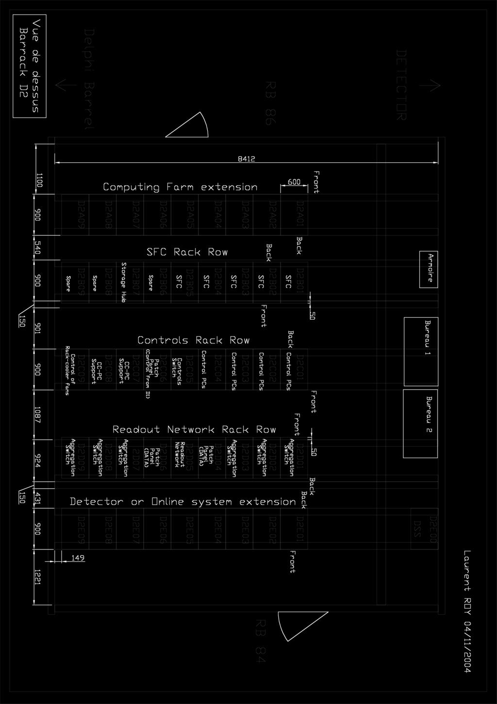
10 D2 Figure 3 Rack-layout in D2 page 8
11 D2 The distribution of the patch-panels in D2 is shown in Table 5. If there are several patch-panels in a rack, then the first one will be mounted at the position indicated in the right-most column as counted from the bottom. The following patch-panels will be mounted in the following higher slots. No space will be left between patch-panels. The remaining racks in D2 are spares and not cabled 4. Table 5 Distribution and position of patch-panels in racks in D2 Rack Function # Patchpanel Position of PP from the top D2B01 SFC 6 back: from the 34th U D2B02 SFC 6 back: from the 34th U D2B03 SFC 6 back: from the 34th U D2B04 SFC 6 back: from the 34th U D2B05 SFC 6 back: from the 34th U D2B07 Storage hub 1 front: from the 29th U D2D02 Spare D2D03 Data aggregation 2 front: from the 50th U D2D04 Data from D3 27 front: from the 50th U D2D05 Data switch 13 front: from the 50th U D2D06 Data from D3 23 front: from the 50th U D2D07 Data aggregation 2 front: from the 50th U D2D08 Spare D2C01 DCSPC 1 back: from the 56th U D2C02 DCSPC 1 back: from the 56th U D2C03 DCSPC 1 back: from the 56th U D2C04 DCSPC 1 back: from the 56th U D2C05 Controls Switch 5 front: from the 50th U D2C06 Control from D1 3 front: from the 29th U D2C07 CCCPC 2 front: from the 29th U D2C08 Controls from D3 16 front: from the 48th U D2C09 Fibers from SX85 Rackcooler Control from D1 1 optical and 3 Cat6 from D1 optical: front: from the 15th U copper: front: from the 39th U 4 The false floor in D2 is not nearly as busy as the three layers in D3. Adding future cables is therefore easy and no installation for possible needs will be done now. page 9

12 D3 4 D3 Barrack D3 houses the sub-detector and the TFC electronics. Figure 4 shows the rack layout in D3. Rack D3A07 and D3A08 are not operated by the online system and will not be cabled with Ethernet. Figure 4 Current rack-layout in D3 (see [1]) page 10
13 D3 4.1 TELL1 crates The major part of connections is needed to connect the TELL1 5 boards to the DAQ network. The TELL1 boards are housed in TELL1 crates. A TELL1 crate can contain a maximum of 20 TELL1- boards. At least one slot must be kept free for the Throttle-OR, if boards in the same crate can belong to different TFC partitions (i.e. they can be driven by different Readout Supervisors, because they have their own connection to the TFC switch), then as many Throttle-ORs as potential partitions must be installed. Each TELL1 needs 4 connections to the DAQ network and one to the Controls Network for its Creditcard PC. That makes 5 Ethernet connections in total per TELL1/UKL1 board. Most detectors will not need all 4 connections, in particular when they do not participate in the Level-1. These additional connections should be viewed as reserve and spares. The TELL1 crates have all Ethernet connections at their back; hence the patch-panel will be mounted also at the back of the rack. A drawing of D3 rack equipped with two TELL1 crates can be seen in Figure 5. The Creditcard PCs will be connected to switches, which are located in the D3 racks. Two types of switches can be used as needed: 48-port and 24-port devices. Only one such device will be maximally installed per rack. For each switch 4 up-links to the ECS network in D2 will be provided. Table 6 Links for TELL1/UKL1 board and crate DAQ links CCPC ECS switch ECS links Total links with 4 up links 1 TELL1/UKL1 4 1 n/a 5 1 full TELL1 crate ( TELL1s and one Throttle-OR) 5 In the following the term TELL1 always includes the UKL1 board, unless explicitly stated otherwise. 6 4 general purpose ECS links will always be provided. page 11


14 D3 Figure 5 Rack with two TELL1 crates page 12
15 D3 4.2 Connections to the Controls Network As discussed above each TELL1 and each Throttle-OR require one connection to the Controls Network. There are other cards in devices in D3, which also require a connection to the ECS network. These include the L0-processing cards and items such as Ethernet controlled powersupplies. In some cases the number of required connections is known and can be seen from Table 7. Moreover in all TELL1 racks 4 additional connections to the Controls Network will be installed. Where no definitive numbers are known, 8 Ethernet connections to the controls network will be provided. These can be used to connect power-supplies and other Ethernet attached devices. If need be the number of connections can easily be increased by installing small network switches in the racks. 4.3 Ethernet connections in D3 racks Table 7 lists all racks in D3 with the number of TELL1/UKL1 boards, if any, the Throttle-ORs and the additional connections to the controls network (labelled ECS in the table). The table follows the attributions of racks to functionalities in sub-detectors prepared by the electronics group [1][2]. Only the indicated number of cables will be installed: i.e. even with there are two crates for 26 TELL1 there will be only 132 links and not 202! Remarks All patch-panels in TELL1 racks are mounted beginning at the 8 th U counting from the bottom of the rack as shown in Figure 5. The patch-panels in the SPARE and POWERSUPPLY racks will be mounted at the 5 th U counting from the bottom see Figure 6. Except for MuonL0 (Figure 7) and TFC all patch-panels will be mounted in the back of the racks 7. 7 This has the additional advantage of leaving front-panel space free for devices which are not too deep (approx 70 cm). page 13


16 D3 Figure 6 Mounting of patch-panel in POWER-SUPPLY / SPARE rack page 14


17 D3 Figure 7 Patch-panel positions in MUON-L0 rack. page 15
18 D3 Table 7 Rack Distributions in D3. The first column names the sub-system; the second gives the designation of the rack, the third the number of TELL1/UKL1 boards UKL1/ TELL1 / RS Throttle OR ECS extra CCPC ECS PP PP pos Total cables MUONL0 D3A f 8 MUONL0 D3A b 0 MUONL0 D3A f 8 MUON D3A b 68 MUON D3A b 8 MUON D3A b 8 CIE D3A b 8 DSS D3A n/a 0 CALOL0 D3B b 8 CALO D3B b 100 CALO D3B b 8 CALO D3B b 8 CALO D3B b 8 L0DU D3B b 19 TFC D3B f 24 TFC D3B f 24 LHC D3B f 12 RICH1 D3C b 52 RICH1 D3C b 12 RICH D3C b 12 RICH2 D3C b 52 RICH2 D3C b 12 SPARE D3C b 8 SPARE D3C b 8 SPARE D3C b 8 OT D3D b 136 OT D3D b 72 OT D3D b 8 OT D3D b 8 OT D3D b 8 OT D3D b 8 IT D3D b 120 IT D3D b 64 IT D3D b 8 PUS D3E b 12 VELO D3E b 148 VELO D3E b 152 VELO D3E b 80 VELO D3E b 8 VELO D3E b 8 TT D3E b 136 TT D3E b 72 TT D3E b 8 page 16
19 D3 page 17
20 Labelling patch-panels as defined by IT/CS 5 Labelling patch-panels as defined by IT/CS There are two types of labels on a patch-panel. On the left-hand side a label with the exact location of the patch-panel can be seen. On top of each plug there is a label which indicates the other end of the connection. To uniquely identify a connection the rack must be known this takes 3 letters (floor, rack-row and rack) the position of the patch-panel within the rack and the plug in the patch panel. The field-codes and their possible values are listed in for the port labels are listed in Table 8 and for the patch-panel labels in Table 9. Table 8 Label on top of ports on patch-panels indicating the other end of this connection Field code Floor Rackrow Rack Patch-panel Port Possible Values D1, D2, D3 A, B, C, D, E 00 to 11 A, B, C,,Z, 0, 1, 2 01,..,24 The Patchpanels are numbered in sequence from top to bottom, A being the top-most patchpanel in a rack. The ports are numbered consecutively from left to right. Table 9 Label at the side of a patch-panel indicating the position of this patch-panel Field code Floor Rackrow Possible Values D1, D2, A, B, C, D3 D, E Rack Patch-panel 0 to 11 A, B, C,,Z, 0, 1,2 As an example consider D1A01A10. This is a label in D2 for a link to a Rack D1A01, a sub-farm rack in D1, the first patch-panel in this rack from the top and port number 10. The reality is shown in Figure 8. page 18

21 DAQ and ECS Ethernet cabling in UXA85 LHCb Technical Note Issue: 2 Labelling patch-panels as defined by IT/CS Reference: Revision: Last modified: EDMS /2 4 22/04/ :55:50 Figure 8 Patchpanel D1C04A in D1 page 19
22 Labelling patch-panels as defined by IT/CS References [1] L. Roy, Drawing Barrack D3, [2] V. Bobillier, Rack distribution in Point 8, [3] W. Witzeling, System and Sub-system Codes, [4] W. Witzeling, Institute Codes, page 20
23 Labelling patch-panels as defined by IT/CS Acronyms and Abbreviations ECS Experiment Control System ELMB Embedded Local Monitor Box LAN PP RS SFC TFC Local Area Network Patch Panel Readout Supervisor Subfarm Controller Timing and Fast Control page 21
24 Labelling patch-panels as defined by IT/CS Labelling of Cables For reference a labelling scheme for the Ethernet cables in the D1, D2 and D3 counting houses compatible with the general LHCb labelling scheme is described here: The cable-label consists of two 14 character alphanumeric lines and a bar-code. The top-line, which is represented also by the bar-code, contains the sub-system code described in [1] and the institute code described in [4]. Top line bar-code Table 10 First (top) line of Ethernet cable label 4 O C C E R class type x x x x x x The first 6 fields are thus fixed for all cables in this document: 4 for LHCb, OC for system (Online) and sub-system (Cable) and CER for the institute (CERN). The eight remaining characters are chosen in the following way. The first ( system ) is a digit describing the cable-class or category of the online project. They are listed in Table 11. The next number type describes the physical type of the cable. The codes are listed in Table 12. Most of the cables in this document will be type 1, copper Ethernet that is in detail: Cat6 UTP cables with RJ45 connector for 10/100/1000 BaseT connections. The remaining 6 digits are a serial number of the cable in decimal notation. Table 11 Online cable class codes Online cable-class Code DAQ 0 ECS 1 Storage Network 2 Table 12 Online cable type codes Cable type Code Ethernet copper 1 Ethernet MMF 2 Ethernet SMF 3 Rackcooler-control copper 4 Table 13 Example of first (top) line of Ethernet cable label 4 O C C E R Consider Table 13 as an example. After the standard LHCb, Online-system Cable, CERN, 0 defines the cable class as DAQ, 1 defines the cable type as Ethernet Copper and is the six page 22
25 Labelling patch-panels as defined by IT/CS digit serial number in decimal notation. Bottom-line This line will contain geographical information, which will allow telling the start and endpoint of the cable. The 14 characters will be re-partioned as shown in Table 14: Table 14 Second geographical line of cable-label Source address Destination address Rack1 Rack2 Rack3 Rack4 PP Port1 Port2 Rack1 Rack2 Rack3 Rack4 PP Port1 Port2 Rack1 to 4 will be the standard designation of the rack as printed on the racks, except for the leading D. PP will be the number of the patch-panel in the rack. Some racks in D2 can have many patch-panels, so we might also use letters here. A patch panel can have a maximum of 24 ports, so Port1 and Port2 will display a number between 1 and 24 in decimal notation. Table 15 Example for the geographical line of the label on Ethernet cables Source address Destination address 3 D D An example is shown in Table 15. This is a label, which describes a cable going from rack D3D07 (a TELL1 rack of the InnerTracker in D3), patch-panel number 4, and port number 10 to rack D2D05 (one of the main patch-panel racks in D2), patch-panel number 9, port number 10 page 23
1 MHz Readout. LHCb Technical Note. Artur Barczyk, Guido Haefeli, Richard Jacobsson, Beat Jost, and Niko Neufeld. Revision: 1.0
 1 MHz Readout LHCb Technical Note Issue: Final Revision: 1.0 Reference: LHCb 2005 62 Created: 9 March, 2005 Last modified: 7 September 2005 Prepared By: Artur Barczyk, Guido Haefeli, Richard Jacobsson,
2008 JINST 3 S Online System. Chapter System decomposition and architecture. 8.2 Data Acquisition System
 Chapter 8 Online System The task of the Online system is to ensure the transfer of data from the front-end electronics to permanent storage under known and controlled conditions. This includes not only
L1 and Subsequent Triggers
 April 8, 2003 L1 and Subsequent Triggers Abstract During the last year the scope of the L1 trigger has changed rather drastically compared to the TP. This note aims at summarising the changes, both in
LHCb Online System BEAUTY-2002
 BEAUTY-2002 8th International Conference on B-Physics at Hadron machines June 17-21 2002 antiago de Compostela, Galicia (pain ) Niko Neufeld, CERN EP (for the LHCb Online Team) 1 Mission The LHCb Online
Level 0 trigger decision unit for the LHCb experiment
 Level 0 trigger decision unit for the LHCb experiment J. Laubser, H. Chanal, R. Cornat, O. Deschamps, M. Magne, P. Perret for the LHCb Collaboration Laboratoire de Physique Corpusculaire (IN2P3/CNRS),
Stefan Koestner on behalf of the LHCb Online Group ( IEEE - Nuclear Science Symposium San Diego, Oct.
 Stefan Koestner on behalf of the LHCb Online Group (email: Stefan.Koestner@cern.ch) IEEE - Nuclear Science Symposium San Diego, Oct. 31 st 2006 Dedicated to B-physics : single arm forward spectrometer
ATLAS TDAQ RoI Builder and the Level 2 Supervisor system
 ATLAS TDAQ RoI Builder and the Level 2 Supervisor system R. E. Blair 1, J. Dawson 1, G. Drake 1, W. Haberichter 1, J. Schlereth 1, M. Abolins 2, Y. Ermoline 2, B. G. Pope 2 1 Argonne National Laboratory,
Detector Control LHC
 Detector Control Systems @ LHC Matthias Richter Department of Physics, University of Oslo IRTG Lecture week Autumn 2012 Oct 18 2012 M. Richter (UiO) DCS @ LHC Oct 09 2012 1 / 39 Detectors in High Energy
IN a system of many electronics boards of many different
 356 IEEE TRANSACTIONS ON NUCLEAR SCIENCE, VOL. 55, NO. 1, FEBRUARY 2008 Building Integrated Remote Control Systems for Electronics Boards Richard Jacobsson, Member, IEEE Abstract This paper addresses several
Velo readout board RB3. Common L1 board (ROB)
") Velo readout board RB3 Testing... Common L1 board (ROB) Specifying Federica Legger 10 February 2003 1 Summary LHCb Detectors Online (Trigger, DAQ) VELO (detector and Readout chain) L1 electronics for VELO
Velo readout board RB3 Testing... Common L1 board (ROB) Specifying Federica Legger 10 February 2003 1 Summary LHCb Detectors Online (Trigger, DAQ) VELO (detector and Readout chain) L1 electronics for VELO
Integration Note. Manufacturer: OVERVIEW AND SUPPORTED FEATURES. Model Number(s): Power Series / 5401
: Power Series / 5401") Manufacturer: DSC Integration Note Model Number(s): Power Series / 5401 Core Module Version: 4.0 (all builds) Comments: Document Revision Date: 1/30/2013 OVERVIEW AND SUPPORTED FEATURES The DSC Power Series
Manufacturer: DSC Integration Note Model Number(s): Power Series / 5401 Core Module Version: 4.0 (all builds) Comments: Document Revision Date: 1/30/2013 OVERVIEW AND SUPPORTED FEATURES The DSC Power Series
Integration Note. Manufacturer: OVERVIEW AND SUPPORTED FEATURES. Model Number(s): DSC POWER SERIES / IT-100
: DSC POWER SERIES / IT-100") Manufacturer: DSC Integration Note Model Number(s): DSC POWER SERIES / IT-100 Core Module Version: 6.4.209 Comments: Document Revision Date: 9/11/2013 OVERVIEW AND SUPPORTED FEATURES The DSC Power Series
Manufacturer: DSC Integration Note Model Number(s): DSC POWER SERIES / IT-100 Core Module Version: 6.4.209 Comments: Document Revision Date: 9/11/2013 OVERVIEW AND SUPPORTED FEATURES The DSC Power Series
The Riser as a Contract Document. Peter Sharp, RCDD
 The Riser as a Contract Document Peter Sharp, RCDD IBI Group 1 1 Who am I? Presenter Credentials Electrical Engineer Specialties in communications, electronics and computer sciences, In practice for 40
Qualification of the optical links for the data readout in LHCb
 Qualification of the optical links for the data readout in LHCb LHCB Technical Note Issue: Draft Revision: 1 Reference: LHCB xxxxx Created: 28 th Jan 2005 Last modified: 11 th Dec 1997 Prepared By: V.
Peter Sharp RCDD IBI Group
 Peter Sharp RCDD IBI Group Who am I? Presenter Credentials Electrical Engineering Consultant Specialties in communications, electronics and computer sciences, In practice for more than 40 years Member
Trends in Data Centre
 Trends in Data Centre The impact on the IT infrastructure Thomas Ko Product Manager Market Situation Standards Update and Topology 40G and 100G Ethernet - Impact on IT Cabling Migration Options with Fiber
Vertex Detector Electronics: ODE to ECS Interface
 Vertex Detector Electronics: ODE to ECS Interface LHCb Technical Note Issue: 1 Revision: 0 Reference: LHCb 2000-012 VELO Created: 1 February 2000 Last modified: 20 March 2000 Prepared By: Yuri Ermoline
MiniDAQ1 A COMPACT DATA ACQUISITION SYSTEM FOR GBT READOUT OVER 10G ETHERNET 22/05/2017 TIPP PAOLO DURANTE - MINIDAQ1 1
 MiniDAQ1 A COMPACT DATA ACQUISITION SYSTEM FOR GBT READOUT OVER 10G ETHERNET 22/05/2017 TIPP 2017 - PAOLO DURANTE - MINIDAQ1 1 Overview LHCb upgrade Optical frontend readout Slow control implementation
Cisco MDS 9000 Family Pluggable Transceivers
 Cisco MDS 9000 Family Pluggable Transceivers The Cisco Small Form-Factor Pluggable (), and X2 devices for use on the Cisco MDS 9000 Family are hot-swappable transceivers that plug into ports on the Cisco
ATLAS TDAQ DATAFLOW. RoI Builder Manual. Abstract ATL-DQ-ON Document Version: 3 Document Issue: 6. Document Date: 22/2/05 Document Status:
 ATLAS ATL-DQ-ON-0005 DATAFLOW RoI Builder Manual Document Version: 3 Document Issue: 6 Document ID: Document Date: 22/2/05 Document Status: ATLAS-TDAQ-2004-XXX Abstract This report describes the ATLAS
Control and Spy the TELL1. Cédric Potterat EPFL LPHE
 Control and Spy the TELL1 Cédric Potterat EPFL LPHE 1 outlines ECS control PVSS for TELL1 DIM, fwccpc, fwhw Status Recipes outlook 2 PVSS CERN Used for the slow control systems by all LHC experiments Open
EMBEDDED PCS FOR ELECTRONICS CONTROL IN LHCB
 10th ICALEPCS Int. Conf. on Accelerator & Large Expt. Physics Control Systems. Geneva, 10-14 Oct 2005, WE1.2-4O (2005) EMBEDDED PCS FOR ELECTRONICS CONTROL IN LHCB F. Fontanelli 1, B. Jost 2, G. Mini 1,
PRIMERGY BX900 System Unit
 PRIMERGY BX900 System Unit System configurator and order-information guide June 2012 Contents Instructions Configuration diagram Configurator I II III IV V VI VII VIII 1 BX900 System Units 2 BX900 Server
Centre de Physique des Particules de Marseille. The PCIe-based readout system for the LHCb experiment
 The PCIe-based readout system for the LHCb experiment K.Arnaud, J.P. Duval, J.P. Cachemiche, Cachemiche,P.-Y. F. Réthoré F. Hachon, M. Jevaud, R. Le Gac, Rethore Centre de Physique des Particules def.marseille
Standards Update. Mylaraiah J N, RCDD Member, BICSI India Steering Committee
 Standards Update Mylaraiah J N, RCDD Member, BICSI India Steering Committee Standards Update International Standards Interrelations Reference Guide Standard ISO/IEC CENELEC TIA/EIA Performance / Generic
BLACKBOX NETWORK SERVICES. one source for worldwide infrastructure services
 BLACKBOX NETWORK SERVICES one source for worldwide infrastructure services 24 Port 10/100Mbps plus 2 Gigabit TX/FX Auto-MDIX Modular Gigabit Ethernet Switch User s Manual FCC Warning This device has been
10/100 AUTO-SENSING MEDIA CONVERTERS
 NxTFAUTOxxx 10/100 AUTO-SENSING MEDIA CONVERTERS 10/100Mbps with auto-negotiation. - or single- versions available. No delays. Front-panel diagnostic LEDs. Auto-sensing. Available in table-top, industrial,
Integration Note. Manufacturer: OVERVIEW AND SUPPORTED FEATURES. Model Number(s): MAXSYS Series
: MAXSYS Series") Manufacturer: DSC Integration Note Model Number(s): MAXSYS Series Core Module Versions: 4.0 (all builds) Comments: Document Revision Date: 1/30/2013 OVERVIEW AND SUPPORTED FEATURES The DSC MAXSYS Series
Manufacturer: DSC Integration Note Model Number(s): MAXSYS Series Core Module Versions: 4.0 (all builds) Comments: Document Revision Date: 1/30/2013 OVERVIEW AND SUPPORTED FEATURES The DSC MAXSYS Series
Traverse System Documentation. Installation and Commissioning Guide
 Force10 Networks Inc. Traverse System Documentation Installation and Commissioning Guide Release TR3.2.2 Publication Date: April 2009 Document Number: 800-0002-TR322 Rev. A Copyright 2009 Force10 Networks,
LRS-12. "Last Mile" SNMP Modem Rack FEATURES
 "Last Mile" SNMP Modem Rack FEATURES Accommodates any combination of 12 HDSL, copper or fiber optic modem cards SNMP management agent Supports modems with or without integrated SNMP agent Management running
MP1220B. ATM Quality Analyzer. A Comprehensive ATM Network Performance Monitoring and Measurement Solution
 MP1220B ATM Quality Analyzer A Comprehensive ATM Network Performance Monitoring and Measurement Solution MP1220B A Comprehensive ATM Network Performance Monitoring and Measurement Solution from Anritsu
Frontend Control Electronics for the LHCb upgrade Hardware realization and test
 First Prototype of the muon Frontend Control Electronics for the LHCb upgrade Hardware realization and test V. Bocci, G. Chiodi, P. Fresch et al. International Conference on Technology and Instrumentation
S-Access TELCO-LINK - series TDM Based SHDSL
 S-Access TELCO-LINK - series TDM Based SHDSL Features 2 and 4 Wire SHDSL (TC-PAM16) E1 (G.703/704, balanced/unbalanced) (V.35, V.36, X.21, V.24) Ethernet Bridge (10/100BaseT) 4 or 8 Analog Voice Ports
ADC KRONE. Data Centre Design Considerations. TrueNet Engineered for Uptime
 ADC KRONE Data Centre Design Considerations Data Centre Building Layout Data centre design should follow set rules Data Centre Logical Layout Data Centre Zones There are four basic designs for cabling
Chapter 4: Network Access. Introduction to Networks v5.1
 Chapter 4: Network Access Introduction to Networks v5.1 4.0 Introduction 4.1 Physical Layer Protocols 4.2 Network Media 4.3 Data Link Layer Protocols 4.4 Media Access Control 4.5 Summary 2013 Cisco and/or
INSTALLATION INSTRUCTIONS FOR THE BV10-100/1000
 INSTALLATION INSTRUCTIONS FOR THE BV10-100/1000 This document describes the basic steps for installing your BV10-100 or BV10-1000. For detailed information about the BV10-100/1000, see the Ethernet Performance
harting Smart Network Infrastructure Selection Guide
 harting Smart Network Infrastructure Selection Guide Selection guide In just a few steps to a complete network With this selection guide you get an easy tool, which supports you in designing your Automation
Total Amount Carried Forward To Bill summary Page
 BILL 1: GROUND FLOOR Supply, Deliver, Install, Set to Work and Commission the Following. 1.01 4 Pair, 24 AWG UTP cable, CAT 6, 305 metres per roll. As siemon or equal &approved equivalent 1.02 CAT 6 Face
InstaPATCH Cu Cabling Solutions for Data Centers
 SYSTIMAX Solutions InstaPATCH Cu Cabling Solutions for Data Centers Design Guidelines August 2008 www.commscope.com Contents Overview 1 InstaPATCH Cu Solution Specification 2 Harness Assembly Design 3
Cisco Series Gigabit Ethernet Half-Height Line Card
 Cisco 10000 Series Gigabit Ethernet Half-Height Line Card Figure 1. Cisco 10000 Series Gigabit Ethernet Half-Height Line Card In order to continue to meet customers increasing needs for modularity and
An ATCA framework for the upgraded ATLAS read out electronics at the LHC
 An ATCA framework for the upgraded ATLAS read out electronics at the LHC Robert Reed School of Physics, University of the Witwatersrand, Johannesburg, South Africa E-mail: robert.reed@cern.ch Abstract.
Installing the H2 -EBC(100), H2 -EBC -F or H4 -EBC( -F)
, H2 -EBC -F or H4 -EBC( -F)") 12 Installing the H2 -EBC(100), H2 -EBC -F or H4 -EBC( -F) In This Chapter Network Identifiers Setting the Module ID The H2 Series EBC DIP Switch The H4 Series EBC DIP Switch Inserting the H2 Series EBC
12 Installing the H2 -EBC(100), H2 -EBC -F or H4 -EBC( -F) In This Chapter Network Identifiers Setting the Module ID The H2 Series EBC DIP Switch The H4 Series EBC DIP Switch Inserting the H2 Series EBC
E. Numbering and Labeling Pathway components. In general, pathway components are not labeled.
 27 05 53 Identification (Labeling) for Communications Systems (Revision date: 3/6/13) 1.0 Purpose A. These guidelines provide requirements for designers to incorporate into bid documents. They are part
KE K HDMI Single Display KVM over IP Extender with PoE
 KE8952 4K HDMI Single Display KVM over IP Extender with PoE ATEN is well known for delivering innovative technologies that drive connectivity and access management solutions. As such, we introduce the
ERX System Overview. The ERX System. This chapter provides information about the system.
 ERX System Overview 1 This chapter provides information about the system. Topic Page The ERX System 1-1 Where the ERX System Fits In 1-6 ERX System Modules 1-7 Network Management Tools 1-11 Redundancy
Metropolis ADM MultiService Mux Compact Shelf
 Metropolis ADM MultiService Mux Compact Shelf Engineering and Ordering Information Release 5.0 ED8C938-10 Issue 5 13-May-2005 AN55 Copyright 2005 Lucent Technologies All Rights Reserved A A About This
The Compact Muon Solenoid Experiment. CMS Note. Mailing address: CMS CERN, CH-1211 GENEVA 23, Switzerland
 Available on CMS information server CMS NOTE 2002/xxx The Compact Muon Solenoid Experiment CMS Note Mailing address: CMS CERN, CH-1211 GENEVA 23, Switzerland Draft of 1 January 2002 Link System and Crate
RPC Trigger Overview
 RPC Trigger Overview presented by Maciek Kudla, Warsaw University RPC Trigger ESR Warsaw, July 8th, 2003 RPC Trigger Task The task of RPC Muon Trigger electronics is to deliver 4 highest momentum muons
Interconnection to MIX - Technical specifications
 Interconnection to MIX - Technical specifications Pag. 1 di 9 DOCUMENT CODE : MIX-302E VERSION : 3.1 DEPARTMENT : TECHNICAL OFFICE STATUS : DEFINITIVE DOCUMENT DATE : 03/03/11 NUMBER OF PAGES : 9 RELEASED
New Product: Cisco Catalyst 2950 Series Fast Ethernet Desktop Switches
 New Product: Cisco Catalyst 2950 Series Fast Ethernet Desktop Switches Product Overview The Cisco Catalyst 2950 Series of fixed configuration, wire-speed Fast Ethernet desktop switches delivers premium
Industrial 5-Port Fast Ethernet Switches. with SFP Slot and optional 4 PoE PSE Ports. Basic Model: KSD-541. PoE Model: KSD-541-HP. Installation Guide
 Industrial 5-Port Fast Ethernet Switches with SFP Slot and optional 4 PoE PSE Ports Basic Model: KSD-541 PoE Model: KSD-541-HP Installation Guide DOC.141201-1- (C) 2014 KTI Networks Inc. All rights reserved.
CERN months. TFC Tutorial. Richard Jacobsson & Zbig Guzik. TFC Tutorial, November 28, 2005
 - 17 months TFC Tutorial Richard Jacobsson & Zbig Guzik 1 Introduction 1 Aim with tutorial Introduce setting up and operating TFC system for detector tests Show an example of the implementation of a complete
Prisma II Platform. Optoelectronics
 Optoelectronics Prisma II Platform Description In optical transmission systems, the network platform forms the foundation of the product family. The Prisma II platform provides network operators with the
JVA Z Series Keypad Bus Wiring Installation Manual
 JVA Z Series Keypad Bus Wiring Version: 1.21 Date: 1 June 2015 By: Miles Norton JVA Technologies Pty Ltd 2013 Version July 2013. Uncontrolled if printed Introducing the Keypad Bus Table of Contents 1 Introducing
Troubleshooting Networking Problems. Understanding your school s network
 Troubleshooting Networking Problems Understanding your school s network by Stu Hasic Feb 2013 Typical Networks All schools use Ethernet Networks There s networks Typical School Networks Almost all schools
CIS-331 Final Exam Fall 2015 Total of 120 Points. Version 1
 Version 1 1. (25 Points) Given that a frame is formatted as follows: And given that a datagram is formatted as follows: And given that a TCP segment is formatted as follows: Assuming no options are present
4x4 HDMI Matrix Switcher and HDMI over HDBaseT CAT5 Extender - 230ft (70m) p
 p") 4x4 HDMI Matrix Switcher and HDMI over HDBaseT CAT5 Extender - 230ft (70m) - 1080p Product ID: ST424HDBT This HDBaseT HDMI Matrix Switch and Cat5 extender is an all-in-one digital signage solution that
4x4 HDMI Matrix Switcher and HDMI over HDBaseT CAT5 Extender - 230ft (70m) - 1080p Product ID: ST424HDBT This HDBaseT HDMI Matrix Switch and Cat5 extender is an all-in-one digital signage solution that
Industrial 5-Port Fast Ethernet Switches with SFP Slot and optional 4 PoE PSE Ports. Basic Model: KSD-541 PoE Model: KSD-541-P. Installation Guide
 Industrial 5-Port Fast Ethernet Switches with SFP Slot and optional 4 PoE PSE Ports Basic Model: KSD-541 PoE Model: KSD-541-P Installation Guide DOC.080104-1- (C) 2008 KTI Networks Inc. All rights reserved.
Deferred High Level Trigger in LHCb: A Boost to CPU Resource Utilization
 Deferred High Level Trigger in LHCb: A Boost to Resource Utilization The use of periods without beam for online high level triggers Introduction, problem statement Realization of the chosen solution Conclusions
Octalink 1U Manual. Octalink 1U. Passive 8-Channel Patchbay. Manual Revision:
 Octalink 1U Passive 8-Channel Patchbay Manual Revision: 2018.08.03 Installation This module is designed for use within an Intellijel-standard 1U row, such as contained within the Intellijel 4U and 7U Eurorack
APV-25 based readout electronics for the SBS front GEM Tracker
 APV-25 based readout electronics for the SBS front GEM Tracker Authors: Evaristo Cisbani, Paolo Musico Date: 26/June/2014 Version: 1.0 APV-25 based readout electronics for the SBS front GEM Tracker...
First Operational Experience from the LHCb Silicon Tracker
 First Operational Experience from the LHCb Silicon Tracker 7 th International Hiroshima Symposium on Development and Application of Semiconductor Tracking Devices The LHCb Silicon Tracker Installation
Introduction to LAN Topologies Cabling. 2000, Cisco Systems, Inc. 3-1
 Introduction to LAN Topologies Cabling 2000, Cisco Systems, Inc. 3-1 Objectives Upon completion of this chapter, you will be able to perform the following tasks: Media / Cabling Local Area Network Cabling
A generic firmware core to drive the Front-End GBT-SCAs for the LHCb upgrade
 Journal of Instrumentation OPEN ACCESS A generic firmware core to drive the Front-End GBT-SCAs for the LHCb upgrade Recent citations - The Versatile Link Demo Board (VLDB) R. Martín Lesma et al To cite
Data channel ports and LAN channel ports will be referred to as channel ports when distinction between the two is not required.
 DROP / INSERT NODES - Item No. CHANNEL PORTS - Item No. Special Provision No. 683S19 September 2007 1. SCOPE This Special Provision covers the requirements for the installation and testing of Field Drop
Loop-O 9300 Fiber Optical Mux
 300 Fiber Optical Mux U height unit U height unit 3U height unit Features Up to 6 E links on one fiber Support Quad RS3 to 6Kbps async (Optional) Support Quad V.35 (Optional) Support 0/00M Bridge (Optional)
Network Components. Network Components 8
 77 PSTN Router Managed Switches Unmanaged Switches Hubs Micro Transceiver Media Converter Network Adapter Ethernet Cable Network Accessories 7 for S7 S5 General Internet Modem Access Router Gateway analog
Integrating Oracle SuperCluster Engineered Systems with a Data Center s 1 GbE and 10 GbE Networks Using Oracle Switch ES1-24
 An Oracle White Paper May 2014 Integrating Oracle SuperCluster Engineered Systems with a Data Center s 1 GbE and 10 GbE s Using Oracle Switch ES1-24 Introduction... 1 Integrating Oracle SuperCluster T5-8
Chapter 7 Hardware Overview
 Chapter 7 Hardware Overview This chapter provides a hardware overview of the HP 9308M, HP 930M, and HP 6308M-SX routing switches and the HP 6208M-SX switch. For information about specific hardware standards
Ethernet Technologies
 Ethernet Technologies CCNA 1 v3 Module 7 NESCOT CATC 1 10 Mbps Ethernet Legacy Ethernet means: 10BASE5 10BASE2 10BASE-T Common features are: frame format timing parameters transmission process basic design
A generic firmware core to drive the Front-End GBT-SCAs for the LHCb upgrade
 A generic firmware core to drive the Front-End GBT-SCAs for the LHCb upgrade F. Alessio 1, C. Caplan, C. Gaspar 1, R. Jacobsson 1, K. Wyllie 1 1 CERN CH-, Switzerland CBPF Rio de Janeiro, Brazil Corresponding
Installing the IPS 4345 and IPS 4360
 CHAPTER 4 Installing the IPS 4345 and IPS 4360 Contents This chapter describes the Cisco IPS 4345 and the IPS 4360, and includes the following sections: Installation Notes and Caveats, page 4-1 Product
Low Profile Hub. User Manual
 16 + 2 Low Profile Hub User Manual 1 Contents One Introduction 2 Two Installation 3 Front Panel Connecting Ports LEDs Three Configuration and Installation Guidelines 5 Hub/Network Configuration Ports and
GÉANT IP Service Description. High Performance IP Services to Support Advanced Research
 GÉANT IP Service Description High Performance IP Services to Support Advanced Research Issue Date: 1 November 2017 GÉANT IP Overview The GÉANT IP service provides high-bandwidth, international Internet
TeamConnect SL TeamConnect CU1, Central Unit, SL TeamConnect CB1, Combox
 1/8 FEATURES Connectivity via landline and PC/VoiP for tele- and web conferencing One solution with high flexibility for end-users Easy to use with ios app or any network device via web server application
CNE301 Network I Lab 04 Building a cross-over cable and configuring back2back network.
 CNE301 Network I Lab 04 Building a cross-over cable and configuring back2back network. # Student ID Student Name Grade (10) 1-1 / 10 - Build a Crossover Cable Objective Build a Category 5 or Category 5e
4K HDMI KVM over IP Extender KE8950 / KE8952
 1 Altusen Enterprise Solutions 4K HDMI KVM over IP Extender KE8950 / KE8952 ATEN is well known for delivering innovative technologies that drive connectivity and access management solutions. As such, we
DYNAMIX HP-51/S HPNA3.1 over Coax Smart Ethernet Bridge. User s Guide V1.0
 DYNAMIX HP-51/S HPNA3.1 over Coax Smart Ethernet Bridge User s Guide V1.0 INTRODUCTION This HCNA (HomePNA3.1 over Coax) to Ethernet bridge connects any Ethernet device to a high speed access device or
CVH Slot Media Converter Chassis Quick Installation Guide
 CVH-2000 14-Slot Media Converter Chassis Quick Installation Guide Ver. 1.2-1305 Table of Contents 1. INTRODUCTION... 1 1.1. FEATURES... 1 1.2. PACKAGE CONTENTS... 1 2. HARDWARE DESCRIPTION... 2 REAL PANEL...
Technical Specification of LHC instrumentation VME crates Back plane, power supplies and transition modules
 Group Code.: SL/BI EDMS No.: 365170 LHC Project document No.: XXXX The Large Hadron Collider Project IT-XXXX/LHC/LHC Technical Specification of LHC instrumentation VME crates Back plane, power supplies
The LHCb upgrade. Outline: Present LHCb detector and trigger LHCb upgrade main drivers Overview of the sub-detector modifications Conclusions
 The LHCb upgrade Burkhard Schmidt for the LHCb Collaboration Outline: Present LHCb detector and trigger LHCb upgrade main drivers Overview of the sub-detector modifications Conclusions OT IT coverage 1.9
Electronics, Trigger and Data Acquisition part 3
 Electronics, Trigger and Data Acquisition part 3 Summer Student Programme 2016, CERN Roberto Ferrari Instituto Nazionale di Fisica Nucleare roberto.ferrari@pv.infn.it Event Building 2 Two Philosophies
Corning Distance and Link-Loss Budgets for the Cisco 40GbE BiDi Transceiver
 9 0 Corning Distance and Link-Loss Budgets for the Cisco 0GbE BiDi Transceiver This paper discusses the following topics for the Cisco bidirectional (BiDi) transceiver: Cisco quad small-form-factor pluggable
Cabling Infrastructure
 Introduction Ethernet Banking on Structured Cabling Technology Drivers Classification of Cables Fibre-optic cable Cables in building Cabling Infrastructure Cabling systems address the networking requirements
10BASE-T/ 10BASE-FL or 100BASE-TX/100BASE-FX compliant. Auto-negotiated data rate and flow control on twisted-pair ports
 enode IP/Ethernet Media Converter Features 10BASE-T/ 10BASE-FL or 100BASE-TX/100BASE-FX compliant Shielded RJ-45 connectors or ST-style connectors Compact size Compatible with LonWorks over IP networks
PoE Powered Gigabit Ethernet Media Converters 1000BASE-T TO 1000BASE-SX/LX. KGC-352 Series. Installation Guide
 PoE Powered Gigabit Ethernet Media Converters 1000BASE-T TO 1000BASE-SX/LX KGC-352 Series Installation Guide DOC.070820-KGC-352-1- (C) 2007 KTI Networks Inc. All rights reserved. No part of this documentation
Cisco Catalyst 4500 Series Line Cards
 Cisco Catalyst 4500 Series Line Cards High Performance, Mobile, and Secure User Experience Product Benefits The Cisco Catalyst 4500 Series Switches enable borderless networks, providing high performance,
Separate 24-bit Read/Write Busses Simple FNAD commanding: e.g. F = 0 (read) N = 1 (crate slot) A = card channel # D = data (either)
 N = 1 (crate slot) A = card channel # D = data (either)") NIM Standard NIM is an acronym for Nuclear Instrumentation Methods. The NIM standard (DOE/ER-0457) was established in 1964 for the nuclear and high energy physics communities. The goal of NIM was to promote
NIM Standard NIM is an acronym for Nuclear Instrumentation Methods. The NIM standard (DOE/ER-0457) was established in 1964 for the nuclear and high energy physics communities. The goal of NIM was to promote
Fiber Management Systems
 FIBER OPTIC PRODUCTS CATALOG OF ALL PRODUCTS WWW..COM Fiber Management Systems Wall Mount Fiber Management System Stand Alone Floor Mount Fiber Rack Mount Fibre Management System Fixed Type ODF Sliding
Lecture (03) Ethernet Protocol & Network Hardware Components
 Ethernet Protocol & Network Hardware Components") Lecture (03) Ethernet Protocol & Network Hardware Components Dr. Ahmed M. ElShafee 1 Agenda Ethernet Protocol/ and cable types Network interface card Network nodes Servers Clients Storage area network
Lecture (03) Ethernet Protocol & Network Hardware Components Dr. Ahmed M. ElShafee 1 Agenda Ethernet Protocol/ and cable types Network interface card Network nodes Servers Clients Storage area network
Optical Networking. Applications
 Applications Allied Telesis Gigabit through 40G optical transport solutions empower IP/Ethernet service providers with a solution that leverages a common family of products and technologies from the customer
4K DisplayPort Single Display KVM over IP Extender
 1 4K DisplayPort Single Display KVM over IP Extender KE9950 / KE9952 The KE9950 / KE9952 4K DisplayPort Single Display KVM over IP Extender consists of a high performance IP-based transmitter (KE9950T
LACCD IT Design Standards
 LACCD IT Design Standards March 1 2009 This document establishes a uniform standard for the design of IT Structured Cabling for LACCD. It ensures a secure, consistent, robust system with physical and low-voltage
Oracle Communications Diameter Signaling Router
 Oracle Communications Diameter Signaling Router Release 6.0 Planning Guide O R A C L E W H I T E P A P E R S E P T E M B E R 2 0 1 4 Table of Contents Acronyms 1 Terminology 1 References 2 Introduction
Introduction to Computer Science (I1100) Networks. Chapter 6
 Networks. Chapter 6") Networks Chapter 6 501 Outline How does Networks and Internet Work? Networking devices Physical Network topology Types of Network Intranets - extranets Copper Media IP Address 502 How does Networks and
Networks Chapter 6 501 Outline How does Networks and Internet Work? Networking devices Physical Network topology Types of Network Intranets - extranets Copper Media IP Address 502 How does Networks and
Instruction Manual MX2-MM-LX-SC MXR2-MM-LX-SC MX2-SM-LX-SC MXR2-SM-LX-SC Media Converter
 Instruction Manual MX2-MM-LX-SC MXR2-MM-LX-SC MX2-SM-LX-SC MXR2-SM-LX-SC Media Converter Copyright 2008, American Fibertek, Inc. 1107JD Table of Contents Functional Description... 3 Installation... 3 MX2
Conflicts in Data Center Fiber Structured Cabling Standards
 Conflicts in Data Center Fiber Structured Cabling Standards By Dave Fredricks, CABLExpress Data Center Infrastructure Architect Various telecommunications and data center (DC)-specific standards are commonly
Lot # 10 - Servers. 1. Rack Server. Rack Server Server
 1. Rack Server Rack Server Server Processor: 1 x Intel Xeon E5 2620v3 (2.4GHz/6 core/15mb/85w) Processor Kit. Upgradable to 2 CPU Chipset: Intel C610 Series Chipset. Intel E5 2600v3 Processor Family. Memory:
Using the SPECS in LHCb
 LHCb 2003-005 DAQ 21 January 2003 Using the in LHCb Dominique Breton, Daniel Charlet Laboratoire de l Accélérateur Linéaire - Orsay ABSTRACT This document attempts to describe how to use the in LHCb. The
M40e and M160 CIP Installation Instructions
 Part No. 530-005365-01 Revision 2 23 January 2002 CIP Description This document describes how to remove and replace the Connector Interface Panel (CIP) on a Juniper Networks M40e Internet router or M160