Lecture 3: The Processor (Chapter 4 of textbook) Chapter 4.1
|
|
|
- Baldwin Barnett
- 6 years ago
- Views:
Transcription
1 Lecture 3: The Processor (Chapter 4 of textbook) Chapter 4.1
2 Introduction Chapter 4.1 Chapter 4.2
3 Review: MIPS (RISC) Design Principles Simplicity favors regularity fixed size instructions small number of instruction formats opcode always the first 6 bits Smaller is faster limited instruction set limited number of registers in register file limited number of addressing modes Make the common case fast arithmetic operands from the register file (load-store machine) allow instructions to contain immediate operands Good design demands good compromises three instruction formats Chapter 4.3
4 The Processor: Datapath & Control Our implementation of the MIPS is simplified memory-reference instructions: lw, sw arithmetic-logical instructions: add, sub, and, or, slt control flow instructions: beq, j Generic implementation use the program counter (PC) to supply the instruction address and fetch the instruction from memory (and update the PC) decode the instruction (and read registers) execute the instruction Exec Fetch PC = PC+4 Decode All instructions (except j) use the after reading the registers How? memory-reference? arithmetic? control flow? Chapter 4.4
5 Logic Design Conventions Chapter 4.2 Chapter 4.5
6 Logic Design Basics Information encoded in binary Low voltage = 0, High voltage = 1 One wire per bit Multi-bit data encoded on multi-wire buses Combinational components Operate on data Output is a function of input State (sequential) components Store information Chapter 4.6
7 Combinational Components AND-gate Y = A & B A B Y Adder Y = A + B A B + Y Multiplexer Y = S? I1 : I0 I0 I1 M u x Y S Arithmetic/Logic Unit Y = F(A,B) A B Y F Chapter 4.7
8 Sequential Components Register: stores data in a circuit Uses a clock signal to determine when to update the stored value Edge-triggered: update when the clock signal changes the value - Rising edge (positive edge) : Falling edge (negative edge) : 1 0 D flip-flop is one option to implement register D Clk Q Clk D Q Chapter 4.8
9 Sequential Components Register with write control Only updates on clock edge when write control input (e.g., Write Enable) is asserted Clk D WE Clk Q WE D Q Chapter 4.9
10 Clocking Methodologies The clocking methodology defines when data in a state element are valid and stable relative to the clock State elements a memory element such as a register Edge-triggered all state changes occur on a clock edge Typical execution read contents of state elements send values through combinational logic write results to one or more state elements State element 1 Combinational logic State element 2 clock one clock cycle Assumes state elements are written on every clock cycle; if not, need explicit write control signal write occurs only when both the write control is asserted and the clock edge occurs Chapter 4.10
11 Building a Datapath Chapter 4.3 Chapter 4.11
12 Fetching Instructions Fetching instructions involves reading the instruction from the Instruction Memory updating the PC value to be the address of the next (sequential) instruction clock Exec Fetch PC = PC+4 Decode PC 4 Address Add Instruction Memory Instruction PC is updated every clock cycle, so it does not need an explicit write control signal Chapter 4.12
13 Decoding Instructions Decoding instructions involves sending the fetched instruction s opcode and function field bits to the control unit Fetch PC = PC+4 Control Unit Exec Decode Instruction Addr 1 Register Addr 2 Data 1 File Write Addr Data 2 Write Data reading two values from the Register File - Register File addresses are contained in the instruction Chapter 4.13
14 Executing R Format Operations R format operations (add, sub, slt, and, or) R-type: op rs rt rd shamt funct perform operation (op and funct) on values in rs and rt store the result back into the Register File (into location rd) RegWrite control Exec Fetch PC = PC+4 Decode Instruction Addr 1 Register Addr 2 Data 1 File Write Addr Data 2 Write Data overflow zero Note that Register File is not written every cycle (e.g., sw), so we need an explicit write control signal for the Register File Chapter 4.14
15 Executing Store Operations Store operations involve compute memory address by adding the base register (read from the Register File during decode) to the 16-bit signed-extended offset field in the instruction store value (read from the Register File during decode) written to the Data Memory control MemWrite Instruction Addr 1 Register Addr 2 Data 1 File Write Addr Data 2 Write Data overflow zero Address Data Memory Write Data Data Sign 16 Extend 32 Chapter 4.15
16 Executing Load Operations Load operations involve compute memory address by adding the base register (read from the Register File during decode) to the 16-bit signed-extended offset field in the instruction load value (read from the Data Memory) written to the Register File RegWrite control Instruction Addr 1 Register Addr 2 Data 1 File Write Addr Data 2 Write Data overflow zero Address Data Memory Write Data Data Sign 16 Extend 32 Mem Chapter 4.16
17 Executing Branch Operations Branch operations involve compare the operands read from the Register File during decode for equality (zero output) compute the branch target address by adding the updated PC to the 16-bit signed-extended offset field in the instr 4 Add Shift left 2 Add Branch target address control PC Instruction Addr 1 Register Addr 2 Data 1 File Write Addr Data 2 Write Data zero (to branch control logic) Sign 16 Extend 32 Chapter 4.17
18 Executing Jump Operations Jump operation involves replace the lower 28 bits of the PC with the lower 26 bits of the fetched instruction shifted left by 2 bits Add 4 4 PC Address Instruction Memory Instruction 26 Shift left 2 28 Jump address Chapter 4.18
19 Creating a Single Datapath from the Parts Assemble the datapath segments and add control lines and multiplexors as needed Single cycle design fetch, decode and execute each instruction in one clock cycle no datapath resource can be used more than once per instruction, so some must be duplicated (e.g., separate Instruction Memory and Data Memory, several adders) multiplexors needed at the input of shared elements with control lines to do the selection write signals to control writing to the Register File and Data Memory Cycle time is determined by the length of the longest path Chapter 4.19
20 Fetch, Register, and Memory Access Portions PC 4 Address Add Instruction Memory Instruction RegWrite Addr 1 Register Addr 2 Data 1 File Write Addr Data 2 Write Data Src control ovf zero MemWrite Address Data Memory Write Data Data MemtoReg Sign 16 Extend 32 Mem zero flag of - 1 : result is zero - 0 : result is not zero Chapter 4.20

")
21 Full Datapath (without Jump) Chapter 4.21
22 Adding Control Units Chapter 4.4, page 259 Chapter 4.22
23 Adding the Control Selecting the operations to perform (, Register File and Memory read/write) Controlling the flow of data (multiplexor inputs) Observations op field always in bits R-type: op rs rt rd shamt funct I-Type: op rs rt address offset addr. of registers J-type: to be read are op always specified by the rs field (bits 25-21) and rt field (bits 20-16) - in lw and sw rs is the base register addr. of register to be written is in one of two places in rt (bits 20-16) for lw; in rd (bits 15-11) for R-type instructions offset for beq, lw, and sw always in bits target address Chapter 4.23
24 The Main Control Unit Control signals derived from instruction R-type Load/ Store Branch 0 rs rt rd shamt funct 31:26 25:21 20:16 15:11 10:6 5:0 35 or 43 rs rt address 31:26 25:21 20:16 15:0 4 rs rt address 31:26 25:21 20:16 15:0 opcode always read always read write for R-type and load sign-extend Chapter 4.24
25 Single Cycle Datapath with Control Unit (w/o jump) 0 4 Add Op Instr[31-26] Control Unit Branch Src Shift left 2 Add 1 PCSrc Mem MemtoReg MemWrite PC Address Instruction Memory Instr[31-0] RegDst Instr[25-21] Instr[20-16] 0 1 Instr[15-11] RegWrite Addr 1 Register Addr 2 Data 1 File Write Addr Data 2 Write Data 0 1 ovf zero Address Data Memory Write Data Data 1 0 Instr[15-0] Sign 16 Extend 32 control Instr[5-0] Chapter 4.25
26 Single Cycle Datapath with Control Unit 4 Add Instr[25-0] 26 Op Instr[31-26] Shift left 2 Control Unit PC+4 [31-28] Jump Branch Src Shift left 2 Add PCSrc Mem MemtoReg MemWrite PC Address Instruction Memory Instr[31-0] RegDst Instr[25-21] Instr[20-16] 0 1 Instr[15-11] RegWrite Addr 1 Register Addr 2 Data 1 File Write Addr Data 2 Write Data 0 1 ovf zero Address Data Memory Write Data Data 1 0 Instr[15-0] Sign 16 Extend 32 control Instr[5-0] Chapter 4.26
27 Control used for Load/Store: Function = add Branch: Function = subtract R-type: Function depends on funct field control Function 0000 AND 0001 OR 0010 add 0110 subtract 0111 set-on-less-than Chapter 4.27
28 Control Assume 2-bit Op derived from opcode Combinational logic derives control opcode Op Operation funct function control lw 00 load word XXXXXX add 0010 sw 00 store word XXXXXX add 0010 beq 01 branch equal XXXXXX subtract 0110 R-type 10 add add 0010 subtract subtract 0110 AND AND 0000 OR OR 0001 set-on-less-than set-on-less-than 0111 Chapter 4.28
29 Single-cycle Implementation Chapter 4.4, page 264 Chapter 4.29
30 R-type Instruction Data/Control Flow 0 4 Add Op Instr[31-26] Control Unit Branch Src Shift left 2 Add 1 PCSrc Mem MemtoReg MemWrite PC Address Instruction Memory Instr[31-0] RegDst Instr[25-21] Instr[20-16] 0 1 Instr[15-11] RegWrite Addr 1 Register Addr 2 Data 1 File Write Addr Data 2 Write Data 0 1 ovf zero Address Data Memory Write Data Data 1 0 Instr[15-0] Sign 16 Extend 32 control Instr[5-0] Chapter 4.30

31 R-type Instruction Data/Control Flow (alt.) Chapter 4.31
32 Load Word Instruction Data/Control Flow 0 4 Add Op Instr[31-26] Control Unit Branch Src Shift left 2 Add 1 PCSrc Mem MemtoReg MemWrite PC Address Instruction Memory Instr[31-0] RegDst Instr[25-21] Instr[20-16] 0 1 Instr[15-11] RegWrite Addr 1 Register Addr 2 Data 1 File Write Addr Data 2 Write Data 0 1 ovf zero Address Data Memory Write Data Data 1 0 Instr[15-0] Sign 16 Extend 32 control Instr[5-0] Chapter 4.32
33 Load Word Instruction Data/Control Flow 0 4 Add Op Instr[31-26] Control Unit Branch Src Shift left 2 Add 1 PCSrc Mem MemtoReg MemWrite PC Address Instruction Memory Instr[31-0] RegDst Instr[25-21] Instr[20-16] 0 1 Instr[15-11] RegWrite Addr 1 Register Addr 2 Data 1 File Write Addr Data 2 Write Data 0 1 ovf zero Address Data Memory Write Data Data 1 0 Instr[15-0] Sign 16 Extend 32 control Instr[5-0] Chapter 4.33

34 Load Word Instruction Data/Control Flow (alt.) Chapter 4.34
35 Store Word Instruction Data/Control Flow 0 4 Add Op Instr[31-26] Control Unit Branch Src Shift left 2 Add 1 PCSrc Mem MemtoReg MemWrite PC Address Instruction Memory Instr[31-0] RegDst Instr[25-21] Instr[20-16] 0 1 Instr[15-11] RegWrite Addr 1 Register Addr 2 Data 1 File Write Addr Data 2 Write Data 0 1 ovf zero Address Data Memory Write Data Data 1 0 Instr[15-0] Sign 16 Extend 32 control Instr[5-0] Chapter 4.35
36 Store Word Instruction Data/Control Flow 0 4 Add Op Instr[31-26] Control Unit Branch Src Shift left 2 Add 1 PCSrc Mem MemtoReg MemWrite PC Address Instruction Memory Instr[31-0] RegDst Instr[25-21] Instr[20-16] 0 1 Instr[15-11] RegWrite Addr 1 Register Addr 2 Data 1 File Write Addr Data 2 Write Data 0 1 ovf zero Address Data Memory Write Data Data 1 0 Instr[15-0] Sign 16 Extend 32 control Instr[5-0] Chapter 4.36
37 Branch Instruction Data/Control Flow 0 4 Add Op Instr[31-26] Control Unit Branch Src Shift left 2 Add 1 PCSrc Mem MemtoReg MemWrite PC Address Instruction Memory Instr[31-0] RegDst Instr[25-21] Instr[20-16] 0 1 Instr[15-11] RegWrite Addr 1 Register Addr 2 Data 1 File Write Addr Data 2 Write Data 0 1 ovf zero Address Data Memory Write Data Data 1 0 Instr[15-0] Sign 16 Extend 32 control Instr[5-0] Chapter 4.37
38 Branch Instruction Data/Control Flow 0 4 Add Op Instr[31-26] Control Unit Branch Src Shift left 2 Add 1 PCSrc Mem MemtoReg MemWrite PC Address Instruction Memory Instr[31-0] RegDst Instr[25-21] Instr[20-16] 0 1 Instr[15-11] RegWrite Addr 1 Register Addr 2 Data 1 File Write Addr Data 2 Write Data 0 1 ovf zero Address Data Memory Write Data Data 1 0 Instr[15-0] Sign 16 Extend 32 control Instr[5-0] Chapter 4.38

39 Branch Instruction Data/Control Flow (alt.) Chapter 4.39
40 Adding the Jump Operation 4 Add Instr[25-0] 26 Op Instr[31-26] Shift left 2 Control Unit PC+4[31-28] Branch Jump Src Shift left 2 Add PCSrc Mem MemtoReg MemWrite PC Address Instruction Memory Instr[31-0] RegDst Instr[25-21] Instr[20-16] 0 1 Instr[15-11] RegWrite Addr 1 Register Addr 2 Data 1 File Write Addr Data 2 Write Data 0 1 ovf zero Address Data Memory Write Data Data 1 0 Instr[15-0] Sign 16 Extend 32 control Instr[5-0] Chapter 4.40


41 Jump Operation (alt.) Chapter 4.41
42 Introduction to Pipelining Design Chapter 4.5 Chapter 4.42
43 Instruction Critical Paths What is the clock cycle time assuming negligible delays for muxes, control unit, sign extension, PC access, shift left 2, wires, setup and hold times except: Instruction Memory and Data Memory (200 ps) and adders (200 ps) Register File access (reads or writes) (100 ps) Instr. I Mem Reg Rd Op D Mem Reg Wr Total R- type load store beq jump Chapter 4.43
44 Single Cycle Disadvantages & Advantages Uses the clock cycle inefficiently the clock cycle must be timed to accommodate the slowest instruction especially problematic for more complex instructions like floating-point multiplication Clk Cycle 1 Cycle 2 lw sw Waste Is slow but Is simple and easy to understand Chapter 4.44
45 How Can We Make It Faster? Start fetching and executing the next instruction before the current one has completed Pipelining modern processors are pipelined for performance Remember the performance equation: CPU time = IC CPI CC Under ideal conditions and with a large number of instructions, the speedup from pipelining is approximately equal to the number of pipe stages A five stage pipeline is nearly five times faster because the CC is nearly five times faster - CPI=1 for single-cycle implementation - CPI 1 for pipelined implementation Chapter 4.45


46 Analogy: Assembly Line v.s. Mechanic Shop Mechanic Shop The mechanic needs to do everything It takes hours to fix just one car Car assembly line Many workers work together - Each worker just puts one or a few components into the car One assembly line can produce hundreds or thousands of cars per day Chapter 4.46
47 The Five Stages of Executing Instruction Cycle 1 Cycle 2 Cycle 3 Cycle 4 Cycle 5 lw IFetch Dec Exec Mem WB IFetch: Instruction Fetch and Update PC Dec: Registers Fetch and Instruction Decode Exec: Execute R-type; calculate memory address; etc. Mem: /write the data from/to the Data Memory WB: Write the result data into the register file Chapter 4.47
48 Why Pipeline? For Performance! Time (clock cycles) I n s t r. Inst 0 Inst 1 Once the pipeline is full, one instruction is completed every cycle, so CPI = 1 O r d e r Inst 2 Inst 3 Inst 4 Time to fill the pipeline Chapter 4.48
49 A Pipelined MIPS Processor Start the next instruction before the current one has completed improves throughput - total amount of work done in a given time instruction latency (execution time, delay time, response time - time from the start of an instruction to its completion) is not reduced Cycle 1 Cycle 2 Cycle 3 Cycle 4 Cycle 5 Cycle 6 Cycle 7 Cycle 8 lw IFetch Dec Exec Mem WB sw IFetch Dec Exec Mem WB R-type IFetch Dec Exec Mem WB - clock cycle (pipeline stage time) is limited by the slowest stage for some stages don t need the whole clock cycle (e.g., WB) Chapter 4.49
50 Single Cycle versus Pipeline Single Cycle Implementation (CC = 800 ps): Clk Cycle 1 Cycle 2 lw sw Waste Pipeline Implementation (CC = 200 ps): lw IFetch Dec Exec Mem WB 400 ps sw IFetch Dec Exec Mem WB R-type IFetch Dec Exec Mem WB To complete an entire instruction in the pipelined case takes 1000 ps (as compared to 800 ps for the single cycle case). Why? How long does each take to complete 1,000,000 instrs? Chapter 4.50
51 Pipelining the MIPS ISA What makes it easy all instructions are the same length (32 bits) - can fetch in the 1 st stage and decode in the 2 nd stage few instruction formats (three) memory operations occur only in loads and stores - can use the execute stage to calculate memory addresses each instruction writes at most one result (i.e., changes the machine state) and does it in the last few pipeline stages (MEM or WB) operands must be aligned in memory so a single data transfer takes only one data memory access Only cover the following 8 instructions as an example lw, sw, add, sub, and, or, slt, beq Chapter 4.51
52 Pipelined Datapath Chapter 4.6, 286 Chapter 4.52


53 MIPS Pipelined Datapath Chapter 4.53


54 Pipeline Registers Need registers between stages Hold information produced in previous cycle 1 0 Chapter 4.54
55 Single-clock-cycle diagram Cycle-by-cycle flow of instructions through the pipelined datapath Single-clock-cycle pipeline diagram Show pipeline usage in a single cycle Highlight resources used in each cycle We will look at single-clock-cycle diagrams for load & store instructions Chapter 4.55
56 IF for Load & Store 1 0 Chapter 4.56

57 ID for Load & Store 1 0 Chapter 4.57
58 EX for Load & Store 1 0 Chapter 4.58


59 MEM for Load 1 0 Chapter 4.59
60 MEM for Store 1 0 Chapter 4.60
61 WB for Load 1 0 Wrong register number Chapter 4.61

62 Corrected Pipelined Datapath 1 0 Chapter 4.62
63 MIPS Pipeline Datapath State registers between each pipeline stage to isolate them IF:IFetch ID:Dec EX:Execute MEM: MemAccess WB: WriteBack IF/ID ID/EX EX/MEM Add PC 4 Instruction Memory Address Addr 1 Register Addr 2Data 1 File Write Addr Data 2 Write Data Shift left 2 Add Address Write Data Data Memory Data MEM/WB Sign 16 Extend 32 System Clock Chapter 4.63
64 Graphically Representing MIPS Pipeline Can help with answering questions like: How many cycles does it take to execute this code? What is the doing during cycle 4? Is there a hazard, why does it occur, and how can it be fixed? Chapter 4.64


65 Multi-Cycle Pipeline Diagram Showing the resource usage Chapter 4.65


66 Multi-Cycle Pipeline Diagram Traditional form Chapter 4.66
67 Pipeline Control Chapter 4.6, page 300 Chapter 4.67


68 Pipelined Control Chapter 4.68


69 Pipelined Control Signals Control signals derived from instructions As in single-cycle implementation Chapter 4.69
70 Pipeline Control IF Stage: read Instr Memory (always asserted) and write PC (on System Clock) ID Stage: no control signals to set Reg Dst EX Stage MEM Stage WB Stage Op1 Op0 Src Brch Mem Mem Write Reg Write Mem toreg R lw sw X X beq X X Chapter 4.70
71 MIPS Pipeline Control Path Modifications 1 0 Chapter 4.71
72 Pipeline Hazards Data Hazard Chapter 4.7, page 303 Chapter 4.72
73 Can Pipelining Get Us Into Trouble? Yes: Pipeline Hazards structural hazards: attempt to use the same resource by two different instructions at the same time - Structural hazards are solved by duplicating the necessary components data hazards: attempt to use data before it is ready - An instruction s source operand(s) are produced by a prior instruction still in the pipeline control hazards: attempt to make a decision about program control flow before the condition has been evaluated and the new PC target address calculated - branch and jump instructions, exceptions Can usually resolve hazards by waiting pipeline control must detect the hazard and take action to resolve hazards Chapter 4.73
74 A Single Memory Would Be a Structural Hazard Time (clock cycles) I n s t r. lw Inst 2 Mem Reg Mem Reg Mem Reg Mem Reg ing data from memory O r d e r Inst 3 Inst 4 Mem Reg Mem Reg Mem Reg Mem Reg Inst 5 ing instruction from memory Mem Reg Mem Reg Fix with separate instr and data memories (I$ and D$) Chapter 4.74
75 How About Register File Access? Time (clock cycles) I n s t r. add $1, Inst 2 Fix simple register file hazard by doing writes in the first half of the cycle and reads in the second half O r d e r Inst 3 add $2,$1, Chapter 4.75
76 Register Usage Can Cause Data Hazards Chapter 4.76
77 Register Usage Can Cause Data Hazards Dependencies backward in time cause hazards I n s t r. O r d e r add $1,$8,$9 sub $4,$1,$5 and $6,$1,$7 or $8,$1,$9 xor $4,$1,$5 After Write data hazard Chapter 4.77
78 Loads Can Cause Data Hazards Dependencies backward in time cause hazards I n s t r. O r d e r lw $1,4($2) sub $4,$1,$5 and $6,$1,$7 or $8,$1,$9 xor $4,$1,$5 Load-use data hazard Another After Write hazard Chapter 4.78
79 Formal Definitions of Data Hazards Consider two instructions i and j, with i occurring before j in program order Three data hazards RAW (read after write) - j tries to read a source before i writes it, so j incorrectly gets the old value WAW (write after write) - j tries to write an operand before it is written by i, leaving the value written by i rather than the value written by j in the destination WAR (write after read) - j tries to write a destination before it is read by i, so i incorrectly gets the new value In the basic 5-stage pipeline, WAW and WAR dependences do not cause any hazards Chapter 4.79
80 One Way to Fix a Data Hazard I n s t r. add $1, stall (insert nop) Can fix data hazard by waiting stall but impacts CPI O r d e r stall (insert nop) sub $4,$1,$5 and $6,$1,$7 Chapter 4.80
81 Another Way to Fix a Data Hazard I n s t r. add $1, sub $4,$1,$5 Fix data hazards by forwarding results as soon as they are available to where they are needed O r d e r and $6,$1,$7 or $8,$1,$9 xor $4,$1,$5 Chapter 4.81
82 Data Forwarding (aka Bypassing) Take the result from the earliest point where it exists in any of the pipeline registers and forward it to the functional units (e.g., the ) that need it in that cycle For functional unit: the inputs can come from any pipeline register rather than just from ID/EX by adding multiplexors to both inputs of the connecting the register write data in EX/MEM or MEM/WB to both mux inputs in the EX s stage adding the proper control hardware to control the new muxes With forwarding the processor can achieve a CPI close to 1 even in the presence of data dependencies Chapter 4.82
83 Forwarding Illustration I n s t r. add $1, sub $4,$1,$5 O r d e r and $6,$7,$1 EX forwarding MEM forwarding Chapter 4.83
84 Detecting the Need to Forward Pass register numbers along pipeline e.g., ID/EX.RegisterRs: register number for Rs stored in ID/EX pipeline register operand register numbers in EX stage are given by ID/EX.RegisterRs, ID/EX.RegisterRt Data hazards only if 1a. EX/MEM.RegisterRd = ID/EX.RegisterRs 1b. EX/MEM.RegisterRd = ID/EX.RegisterRt 2a. MEM/WB.RegisterRd = ID/EX.RegisterRs 2b. MEM/WB.RegisterRd = ID/EX.RegisterRt Fwd from previous instr., i.e., EX/MEM pipeline register Fwd from second previous instruction, i.e., MEM/WB pipeline register Chapter 4.84
85 Detecting the Need to Forward But only if forwarding instruction will write to a register! EX/MEM.RegWrite MEM/WB.RegWrite And only if Rd for that instruction is not $zero EX/MEM.RegisterRd 0 MEM/WB.RegisterRd 0 Chapter 4.85
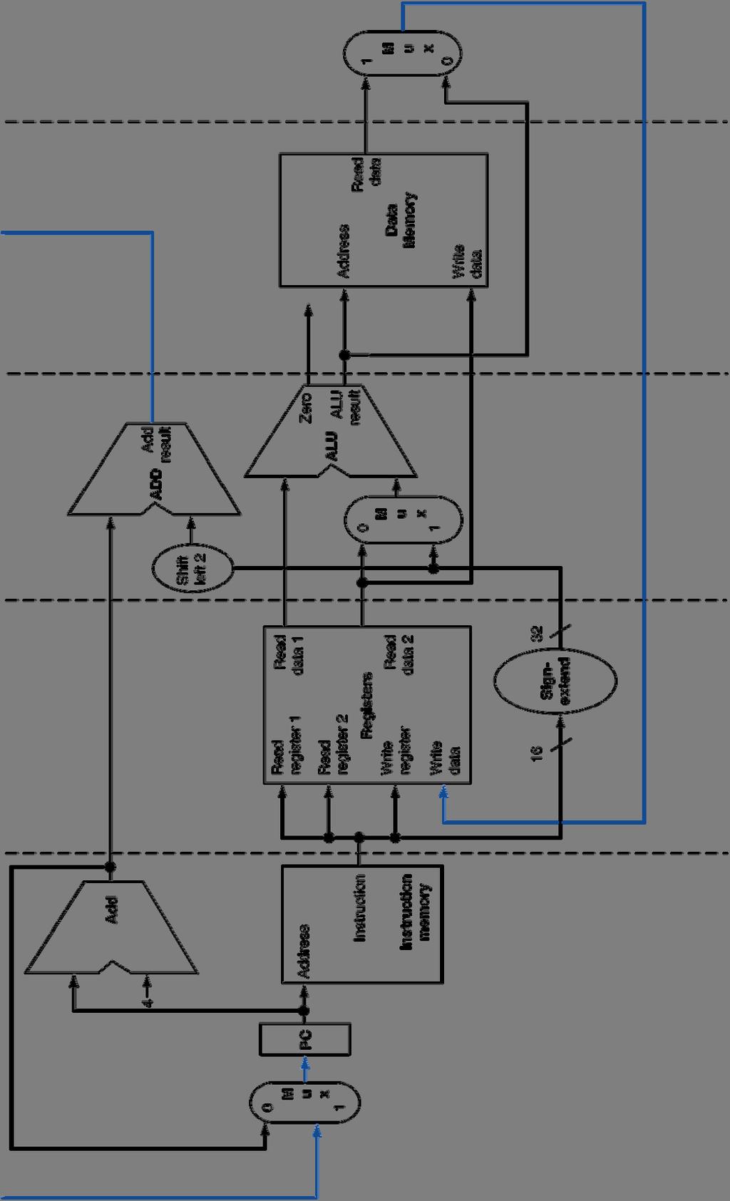
86 Datapath with Forwarding Hardware PCSrc IF/ID Control ID/EX WB M EX EX/MEM WB M PC 4 Instruction Memory Address Add Addr 1 Register Addr 2Data 1 File Write Addr Data 2 Write Data 16 Sign 32 Extend Shift left 2 Add cntrl ForwardA Branch Data Memory Address Data Write Data MEM/WB WB ForwardB Forward Unit Chapter 4.86
87 Control Values for the Forwarding Multiplexors Mux control Source Explanation ForwardA=00 ID/EX The first operand comes from the register file. ForwardA=10 EX/MEM The first operand is forwarded from the prior result. ForwardA=01 MEM/WB The first operand is forwarded from the data memory or an earlier result. ForwardB=00 ID/EX The second operand comes from the register file. ForwardB=10 EX/MEM The second operand is forwarded from the prior result. ForwardB=01 MEM/WB The second operand is forwarded from the data memory or an earlier result. Chapter 4.87
88 Yet Another Complication! Another potential data hazard can occur when there is a conflict between the outputs of EX/MEM pipeline register and MEM/WB pipeline register which should be forwarded? I n s t r. O r d e r add $1,$1,$2 add $1,$1,$3 add $1,$1,$4 Chapter 4.88
89 Yet Another Complication! Another potential data hazard can occur when there is a conflict between the outputs of EX/MEM pipeline register and MEM/WB pipeline register which should be forwarded? I n s t r. O r d e r add $1,$1,$2 add $1,$1,$3 add $1,$1,$4 What we want The forwarding we want to avoid Chapter 4.89
90 Statement for Forwarding Control Signals (in C) 1. ForwardA: if ( EX/MEM.RegWrite and (EX/MEM.RegisterRd!= 0) and (EX/MEM.RegisterRd = ID/EX.RegisterRs)) ForwardA = 10; Forwards the result from the previous instr. to either input of the Forwards the else if ( MEM/WB.RegWrite and result from the (MEM/WB.RegisterRd!= 0) and second previous (MEM/WB.RegisterRd = ID/EX.RegisterRs)) ForwardA = 01; instr. to either input of the else ForwardA = 00; No forwarding 2. ForwardB The logic is similar Chapter 4.90
91 Datapath with Forwarding Hardware PCSrc IF/ID Control ID/EX WB M EX EX/MEM WB M PC 4 Instruction Memory Address Add Addr 1 Register Addr 2Data 1 File Write Addr Data 2 Write Data 16 Sign 32 Extend Shift left 2 Add cntrl Branch Data Memory Address Data Write Data MEM/WB WB EX/MEM.RegisterRd ID/EX.RegisterRt ID/EX.RegisterRs Forward Unit MEM/WB.RegisterRd Chapter 4.91
92 Data Hazards and Stalls Chapter 4.7, page 313 Chapter 4.92
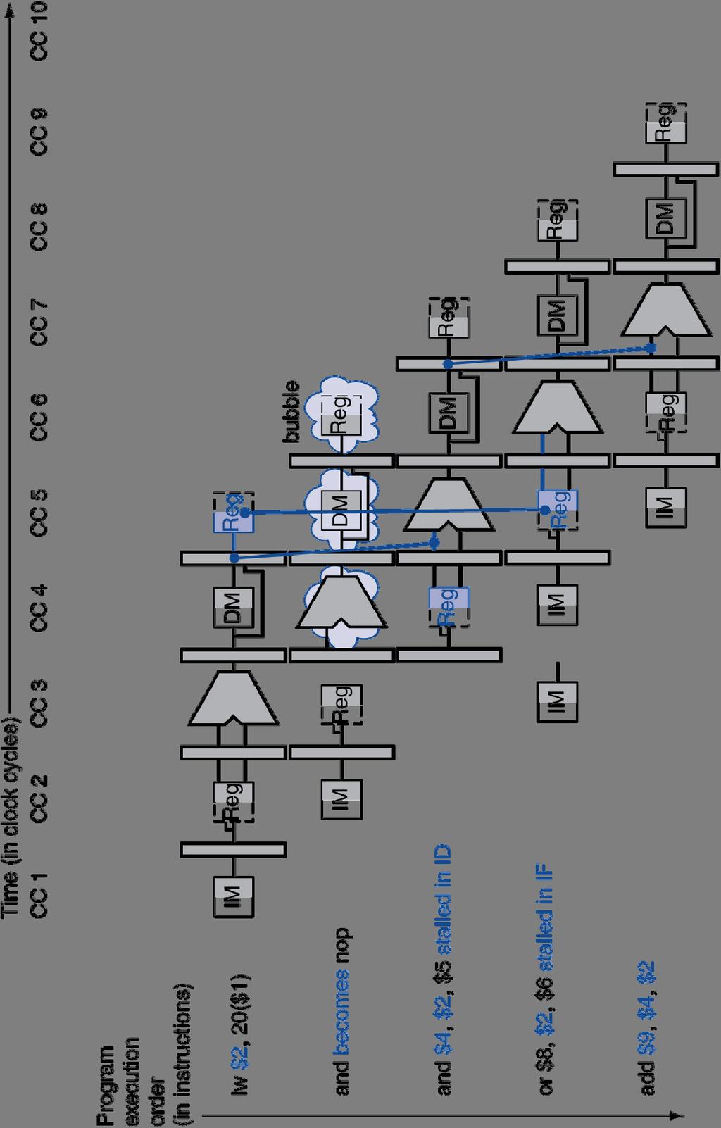
93 Forwarding with Load-use Data Hazards (logical view) I n s t r. O r d e r lw $1,4($2) sub $4,$1,$5 and $6,$1,$7 or $8,$1,$9 xor $4,$1,$5 Chapter 4.93
94 Forwarding with Load-use Data Hazards (logical view) I n s t r. O r d e r lw $1,4($2) sub stall $4,$1,$5 sub $4,$1,$5 and $6,$1,$7 or $8,$1,$9 Reg DM Reg IM xor $4,$1,$5 IM Reg DM Will still need one stall cycle even with forwarding Chapter 4.94
95 Load-use Hazard Detection Unit Need a Hazard detection Unit in the ID stage that inserts a stall between the load and its use 1. ID Hazard detection Unit: if (ID/EX.Mem and ((ID/EX.RegisterRt = IF/ID.RegisterRs) or (ID/EX.RegisterRt = IF/ID.RegisterRt))) stall the pipeline (more accurate, stall the following instructions) The first line tests to see if the instruction now in the EX stage is a lw; the next two lines check to see if the destination register of the lw matches either source register of the instruction in the ID stage (the load-use instruction) After this one cycle stall, the forwarding logic can handle the remaining data hazards Chapter 4.95
96 Hazard/Stall Hardware Along with the Hazard Unit, we have to implement the stall Prevent the instructions in the IF and ID stages from progressing down the pipeline done by preventing the PC register and the IF/ID pipeline register from changing Hazard detection Unit controls the writing of the PC (PC.write) and IF/ID (IF/ID.write) registers Insert a bubble between the lw instruction (in the EX stage) and the load-use instruction (in the ID stage) (i.e., insert a nop in the execution stream) Set the control bits in the EX, MEM, and WB control fields of the ID/EX pipeline register to 0 (nop). The Hazard Unit controls the mux that chooses between the real control values and the 0 s. Let the lw instruction and the following instructions in the pipeline proceed normally down the pipeline Chapter 4.96
97 Adding the Hazard/Stall Hardware PCSrc PC 4 Instruction Memory Address Add IF/ID Hazard Unit Control Addr 1 Register Addr 2Data 1 File Write Addr Data 2 Write Data 16 Sign 32 Extend ID/EX WB M EX ID/EX.Mem Shift left 2 Add cntrl EX/MEM WB M Branch Data Memory Address Data Write Data MEM/WB WB ID/EX.RegisterRt Forward Unit Chapter 4.97
98 Stall/Bubble in the Pipeline Chapter 4.98
99 A Challenge: Memory-to-Memory Copies For loads immediately followed by stores (memory-tomemory copies), a stall can be avoided by adding forwarding hardware from the MEM/WB register to the data memory input. Would need to add a Forward Unit and a mux to the MEM stage I n s t r. O r d e r lw $1,4($2) sw $1,4($3) Chapter 4.99
100 Control Hazards Chapter 4.8 Chapter 4.100


101 MIPS Pipeline Control Path Modifications 1 0 Chapter 4.101
102 Control Hazards When the flow of instruction addresses is not sequential (i.e., PC PC + 4); incurred by change of flow instructions Unconditional branches (j, jal, jr) Conditional branches (beq, bne) Exceptions Possible approaches Stall (impacts CPI) Move decision point as early in the pipeline as possible, thereby reducing the number of stall cycles Predict and hope for the best! Delay decision (requires compiler support) Control hazards occur less frequently than data hazards, but there is nothing as effective against control hazards as forwarding is for data hazards Chapter 4.102
103 Branch Instr s Cause Control Hazards Dependencies backward in time cause hazards I n s t r. O r d e r beq lw Inst 3 Inst 4 Chapter 4.103
104 One Way to Fix a Branch Control Hazard I n s t r. beq flush Fix branch hazard by waiting flush but affects CPI O r d e r flush flush beq target Inst 3 IM Reg DM Chapter 4.104
105 Another Way to Fix a Branch Control Hazard Move branch decision hardware as early in the pipeline as possible, i.e., during the decode cycle I n s t r. O r d e r beq flush beq target Inst 3 IM Reg DM Chapter 4.105
106 Reducing the Delay of Branches Add hardware to compute the branch target address and evaluate the branch decision to the ID stage Reduces the number of stall (flush) cycles to one (like with jumps) - But now need to add forwarding hardware in ID stage Comparing and updating the PC adds 2 muxes, a comparator, and an and gate to the ID stage - Computing branch target address can be done in parallel with RegFile read (done for all instructions only used when needed) - Comparing the registers can be done in the same clock cycle as RegFile read For deeper pipelines, branch decision points can be even later in the pipeline, incurring more stalls Chapter 4.106
107 Supporting ID Stage Branches PCSrc Branch Hazard Unit 0 1 ID/EX EX/MEM IF/ID Control 0 PC 4 Add Instruction Memory 0 Address IF.Flush Shift left 2 Addr 1 RegFile Addr 2 Data 1 Write Addr Data 2 Write Data 16 Sign Extend Add 32 Compare cntrl Data Memory Data Address Write Data MEM/WB Forward Unit Forward Unit Chapter 4.107
108 Example: Branch Taken Example 36: sub $10, $4, $8 40: beq $1, $3, 7 44: and $12, $2, $5 48: or $13, $2, $6 52: add $14, $4, $2 56: slt $15, $6, $ : add $1, $2, $3 72: lw $4, 50($7) 76: and $3, $1, $2 Chapter 4.108


109 Example: Branch Taken Chapter 4.109


110 Example: Branch Taken Chapter 4.110
111 Data Hazards for Branches If a comparison register is a destination of 2 nd preceding instruction Can resolve using forwarding add $1, $2, $3 IF ID EX MEM WB add $4, $5, $6 IF ID EX MEM WB Inst 3 IF ID EX MEM WB beq $1, $4, target IF ID EX MEM WB Chapter 4.111
112 Data Hazards for Branches If a comparison register is a destination of preceding instruction or 2 nd preceding load instruction Need 1 stall cycle lw $1, addr IF ID EX MEM WB add $4, $5, $6 IF ID EX MEM WB beq stalled IF ID beq $1, $4, target ID EX MEM WB Chapter 4.112
113 Data Hazards for Branches If a comparison register is a destination of immediately preceding load instruction Need 2 stall cycles But no data forwarding lw $1, addr IF ID EX MEM WB beq stalled IF ID beq stalled ID beq $1, $0, target ID EX MEM WB Chapter 4.113
114 Summary All modern processors use pipelining for performance (a CPI close to 1 and fast clock frequency) Pipeline clock rate limited by slowest pipeline stage so designing a balanced pipeline is important Pipelining doesn t decrease the latency of single task, it increases the throughput of entire workload Must detect and resolve hazards Structural hazards resolved by designing the pipeline correctly Data hazards - Stall (impacts CPI) - Forward (requires hardware support) Control hazards put the branch decision hardware in as early a stage in the pipeline as possible - Stall (impacts CPI) - Static and dynamic prediction (requires hardware support) - Delay decision (requires compiler support) Chapter 4.114
Chapter 4 The Processor 1. Chapter 4A. The Processor
 Chapter 4 The Processor 1 Chapter 4A The Processor Chapter 4 The Processor 2 Introduction CPU performance factors Instruction count Determined by ISA and compiler CPI and Cycle time Determined by CPU hardware
Chapter 4. The Processor
 Chapter 4 The Processor Introduction CPU performance factors Instruction count Determined by ISA and compiler CPI and Cycle time Determined by CPU hardware We will examine two MIPS implementations A simplified
COMPUTER ORGANIZATION AND DESIGN
 COMPUTER ORGANIZATION AND DESIGN The Hardware/Software Interface 5 th Edition Chapter 4 The Processor Introduction CPU performance factors Instruction count Determined by ISA and compiler CPI and Cycle
The Processor. Z. Jerry Shi Department of Computer Science and Engineering University of Connecticut. CSE3666: Introduction to Computer Architecture
 The Processor Z. Jerry Shi Department of Computer Science and Engineering University of Connecticut CSE3666: Introduction to Computer Architecture Introduction CPU performance factors Instruction count
COMPUTER ORGANIZATION AND DESIGN
 COMPUTER ORGANIZATION AND DESIGN 5 Edition th The Hardware/Software Interface Chapter 4 The Processor 4.1 Introduction Introduction CPU performance factors Instruction count CPI and Cycle time Determined
CENG 3420 Lecture 06: Pipeline
 CENG 3420 Lecture 06: Pipeline Bei Yu byu@cse.cuhk.edu.hk CENG3420 L06.1 Spring 2019 Outline q Pipeline Motivations q Pipeline Hazards q Exceptions q Background: Flip-Flop Control Signals CENG3420 L06.2
Chapter 4 The Processor 1. Chapter 4B. The Processor
 Chapter 4 The Processor 1 Chapter 4B The Processor Chapter 4 The Processor 2 Control Hazards Branch determines flow of control Fetching next instruction depends on branch outcome Pipeline can t always
Department of Computer and IT Engineering University of Kurdistan. Computer Architecture Pipelining. By: Dr. Alireza Abdollahpouri
 Department of Computer and IT Engineering University of Kurdistan Computer Architecture Pipelining By: Dr. Alireza Abdollahpouri Pipelined MIPS processor Any instruction set can be implemented in many
Pipelining Analogy. Pipelined laundry: overlapping execution. Parallelism improves performance. Four loads: Non-stop: Speedup = 8/3.5 = 2.3.
 Pipelining Analogy Pipelined laundry: overlapping execution Parallelism improves performance Four loads: Speedup = 8/3.5 = 2.3 Non-stop: Speedup =2n/05n+15 2n/0.5n 1.5 4 = number of stages 4.5 An Overview
CENG 3420 Computer Organization and Design. Lecture 06: MIPS Processor - I. Bei Yu
 CENG 342 Computer Organization and Design Lecture 6: MIPS Processor - I Bei Yu CEG342 L6. Spring 26 The Processor: Datapath & Control q We're ready to look at an implementation of the MIPS q Simplified
COMPUTER ORGANIZATION AND DESIGN The Hardware/Software Interface. 5 th. Edition. Chapter 4. The Processor
 COMPUTER ORGANIZATION AND DESIGN The Hardware/Software Interface 5 th Edition Chapter 4 The Processor Introduction CPU performance factors Instruction count Determined by ISA and compiler CPI and Cycle
CPE 335 Computer Organization. Basic MIPS Architecture Part I
 CPE 335 Computer Organization Basic MIPS Architecture Part I Dr. Iyad Jafar Adapted from Dr. Gheith Abandah slides http://www.abandah.com/gheith/courses/cpe335_s8/index.html CPE232 Basic MIPS Architecture
14:332:331 Pipelined Datapath
 14:332:331 Pipelined Datapath I n s t r. O r d e r Inst 0 Inst 1 Inst 2 Inst 3 Inst 4 Single Cycle Disadvantages & Advantages Uses the clock cycle inefficiently the clock cycle must be timed to accommodate
CENG 3420 Lecture 06: Datapath
 CENG 342 Lecture 6: Datapath Bei Yu byu@cse.cuhk.edu.hk CENG342 L6. Spring 27 The Processor: Datapath & Control q We're ready to look at an implementation of the MIPS q Simplified to contain only: memory-reference
Pipeline Hazards. Jin-Soo Kim Computer Systems Laboratory Sungkyunkwan University
 Pipeline Hazards Jin-Soo Kim (jinsookim@skku.edu) Computer Systems Laboratory Sungkyunkwan University http://csl.skku.edu Hazards What are hazards? Situations that prevent starting the next instruction
Full Datapath. Chapter 4 The Processor 2
 Pipelining Full Datapath Chapter 4 The Processor 2 Datapath With Control Chapter 4 The Processor 3 Performance Issues Longest delay determines clock period Critical path: load instruction Instruction memory
Processor (II) - pipelining. Hwansoo Han
 - pipelining. Hwansoo Han") Processor (II) - pipelining Hwansoo Han Pipelining Analogy Pipelined laundry: overlapping execution Parallelism improves performance Four loads: Speedup = 8/3.5 =2.3 Non-stop: 2n/0.5n + 1.5 4 = number
Processor (II) - pipelining Hwansoo Han Pipelining Analogy Pipelined laundry: overlapping execution Parallelism improves performance Four loads: Speedup = 8/3.5 =2.3 Non-stop: 2n/0.5n + 1.5 4 = number
CSEE 3827: Fundamentals of Computer Systems
 CSEE 3827: Fundamentals of Computer Systems Lecture 21 and 22 April 22 and 27, 2009 martha@cs.columbia.edu Amdahl s Law Be aware when optimizing... T = improved Taffected improvement factor + T unaffected
ECS 154B Computer Architecture II Spring 2009
 ECS 154B Computer Architecture II Spring 2009 Pipelining Datapath and Control 6.2-6.3 Partially adapted from slides by Mary Jane Irwin, Penn State And Kurtis Kredo, UCD Pipelined CPU Break execution into
LECTURE 3: THE PROCESSOR
 LECTURE 3: THE PROCESSOR Abridged version of Patterson & Hennessy (2013):Ch.4 Introduction CPU performance factors Instruction count Determined by ISA and compiler CPI and Cycle time Determined by CPU
Full Datapath. Chapter 4 The Processor 2
 Pipelining Full Datapath Chapter 4 The Processor 2 Datapath With Control Chapter 4 The Processor 3 Performance Issues Longest delay determines clock period Critical path: load instruction Instruction memory
Computer Organization and Structure. Bing-Yu Chen National Taiwan University
 Computer Organization and Structure Bing-Yu Chen National Taiwan University The Processor Logic Design Conventions Building a Datapath A Simple Implementation Scheme An Overview of Pipelining Pipelined
COMPUTER ORGANIZATION AND DESIGN. 5 th Edition. The Hardware/Software Interface. Chapter 4. The Processor
 COMPUTER ORGANIZATION AND DESIGN The Hardware/Software Interface 5 th Edition Chapter 4 The Processor Introduction CPU performance factors Instruction count Determined by ISA and compiler CPI and Cycle
CO Computer Architecture and Programming Languages CAPL. Lecture 18 & 19
 CO2-3224 Computer Architecture and Programming Languages CAPL Lecture 8 & 9 Dr. Kinga Lipskoch Fall 27 Single Cycle Disadvantages & Advantages Uses the clock cycle inefficiently the clock cycle must be
Outline Marquette University
 COEN-4710 Computer Hardware Lecture 4 Processor Part 2: Pipelining (Ch.4) Cristinel Ababei Department of Electrical and Computer Engineering Credits: Slides adapted primarily from presentations from Mike
COMPUTER ORGANIZATION AND DESIGN. 5 th Edition. The Hardware/Software Interface. Chapter 4. The Processor
 COMPUTER ORGANIZATION AND DESIGN The Hardware/Software Interface 5 th Edition Chapter 4 The Processor COMPUTER ORGANIZATION AND DESIGN The Hardware/Software Interface 5 th Edition The Processor - Introduction
Chapter 4. Instruction Execution. Introduction. CPU Overview. Multiplexers. Chapter 4 The Processor 1. The Processor.
 COMPUTER ORGANIZATION AND DESIGN The Hardware/Software Interface 5 th Edition COMPUTER ORGANIZATION AND DESIGN The Hardware/Software Interface 5 th Edition Chapter 4 The Processor The Processor - Introduction
The Processor (3) Jinkyu Jeong Computer Systems Laboratory Sungkyunkwan University
 Jinkyu Jeong Computer Systems Laboratory Sungkyunkwan University") The Processor (3) Jinkyu Jeong (jinkyu@skku.edu) Computer Systems Laboratory Sungkyunkwan University http://csl.skku.edu EEE3050: Theory on Computer Architectures, Spring 2017, Jinkyu Jeong (jinkyu@skku.edu)
The Processor (3) Jinkyu Jeong (jinkyu@skku.edu) Computer Systems Laboratory Sungkyunkwan University http://csl.skku.edu EEE3050: Theory on Computer Architectures, Spring 2017, Jinkyu Jeong (jinkyu@skku.edu)
Chapter 4. The Processor
 Chapter 4 The Processor Introduction CPU performance factors Instruction count Determined by ISA and compiler CPI and Cycle time Determined by CPU hardware We will examine two MIPS implementations A simplified
Chapter 4. The Processor
 Chapter 4 The Processor 1 Introduction CPU performance factors Instruction count Determined by ISA and compiler CPI and Cycle time Determined by CPU hardware We will examine two MIPS implementations A
Lecture Topics. Announcements. Today: Data and Control Hazards (P&H ) Next: continued. Exam #1 returned. Milestone #5 (due 2/27)
 Next: continued. Exam #1 returned. Milestone #5 (due 2/27)") Lecture Topics Today: Data and Control Hazards (P&H 4.7-4.8) Next: continued 1 Announcements Exam #1 returned Milestone #5 (due 2/27) Milestone #6 (due 3/13) 2 1 Review: Pipelined Implementations Pipelining
Lecture Topics Today: Data and Control Hazards (P&H 4.7-4.8) Next: continued 1 Announcements Exam #1 returned Milestone #5 (due 2/27) Milestone #6 (due 3/13) 2 1 Review: Pipelined Implementations Pipelining
Lecture 7 Pipelining. Peng Liu.
 Lecture 7 Pipelining Peng Liu liupeng@zju.edu.cn 1 Review: The Single Cycle Processor 2 Review: Given Datapath,RTL -> Control Instruction Inst Memory Adr Op Fun Rt
Computer Architecture Computer Science & Engineering. Chapter 4. The Processor BK TP.HCM
 Computer Architecture Computer Science & Engineering Chapter 4 The Processor Introduction CPU performance factors Instruction count Determined by ISA and compiler CPI and Cycle time Determined by CPU hardware
Determined by ISA and compiler. We will examine two MIPS implementations. A simplified version A more realistic pipelined version
 MIPS Processor Introduction CPU performance factors Instruction count Determined by ISA and compiler CPI and Cycle time Determined by CPU hardware We will examine two MIPS implementations A simplified
Review: Abstract Implementation View
 Review: Abstract Implementation View Split memory (Harvard) model - single cycle operation Simplified to contain only the instructions: memory-reference instructions: lw, sw arithmetic-logical instructions:
ECE260: Fundamentals of Computer Engineering
 Data Hazards in a Pipelined Datapath James Moscola Dept. of Engineering & Computer Science York College of Pennsylvania Based on Computer Organization and Design, 5th Edition by Patterson & Hennessy Data
Processor (I) - datapath & control. Hwansoo Han
 - datapath & control. Hwansoo Han") Processor (I) - datapath & control Hwansoo Han Introduction CPU performance factors Instruction count - Determined by ISA and compiler CPI and Cycle time - Determined by CPU hardware We will examine two
Processor (I) - datapath & control Hwansoo Han Introduction CPU performance factors Instruction count - Determined by ISA and compiler CPI and Cycle time - Determined by CPU hardware We will examine two
Chapter 4. The Processor
 Chapter 4 The Processor Recall. ISA? Instruction Fetch Instruction Decode Operand Fetch Execute Result Store Next Instruction Instruction Format or Encoding how is it decoded? Location of operands and
Chapter 4. The Processor
 Chapter 4 The Processor Introduction CPU performance factors Instruction count Determined by ISA and compiler CPI and Cycle time Determined by CPU hardware We will examine two MIPS implementations A simplified
Pipelined datapath Staging data. CS2504, Spring'2007 Dimitris Nikolopoulos
 Pipelined datapath Staging data b 55 Life of a load in the MIPS pipeline Note: both the instruction and the incremented PC value need to be forwarded in the next stage (in case the instruction is a beq)
Chapter 4. The Processor
 Chapter 4 The Processor 4.1 Introduction Introduction CPU performance factors Instruction count CPI and Cycle time Determined by CPU hardware We will examine two MIPS implementations Determined by ISA
zhandling Data Hazards The objectives of this module are to discuss how data hazards are handled in general and also in the MIPS architecture.
 zhandling Data Hazards The objectives of this module are to discuss how data hazards are handled in general and also in the MIPS architecture. We have already discussed in the previous module that true
Thomas Polzer Institut für Technische Informatik
 Thomas Polzer tpolzer@ecs.tuwien.ac.at Institut für Technische Informatik Pipelined laundry: overlapping execution Parallelism improves performance Four loads: Speedup = 8/3.5 = 2.3 Non-stop: Speedup =
Chapter 4. The Processor
 Chapter 4 The Processor Introduction CPU performance factors Instruction count Determined by ISA and compiler CPI and Cycle time Determined by CPU hardware 4.1 Introduction We will examine two MIPS implementations
Computer Architecture Computer Science & Engineering. Chapter 4. The Processor BK TP.HCM
 Computer Architecture Computer Science & Engineering Chapter 4 The Processor Introduction CPU performance factors Instruction count Determined by ISA and compiler CPI and Cycle time Determined by CPU hardware
COMPUTER ORGANIZATION AND DESIGN The Hardware/Software Interface 5 th Edition. Chapter 4. The Processor
 COMPUTER ORGANIZATION AND DESIGN The Hardware/Software Interface 5 th Edition Chapter 4 The Processor The Processor? Chapter 4 The Processor 2 Introduction We will learn How the ISA determines many aspects
EIE/ENE 334 Microprocessors
 EIE/ENE 334 Microprocessors Lecture 6: The Processor Week #06/07 : Dejwoot KHAWPARISUTH Adapted from Computer Organization and Design, 4 th Edition, Patterson & Hennessy, 2009, Elsevier (MK) http://webstaff.kmutt.ac.th/~dejwoot.kha/
COMPUTER ORGANIZATION AND DESIGN
 ARM COMPUTER ORGANIZATION AND DESIGN Edition The Hardware/Software Interface Chapter 4 The Processor Modified and extended by R.J. Leduc - 2016 To understand this chapter, you will need to understand some
ELEC 5200/6200 Computer Architecture and Design Spring 2017 Lecture 4: Datapath and Control
 ELEC 52/62 Computer Architecture and Design Spring 217 Lecture 4: Datapath and Control Ujjwal Guin, Assistant Professor Department of Electrical and Computer Engineering Auburn University, Auburn, AL 36849
Computer Architecture. Lecture 6.1: Fundamentals of
 CS3350B Computer Architecture Winter 2015 Lecture 6.1: Fundamentals of Instructional Level Parallelism Marc Moreno Maza www.csd.uwo.ca/courses/cs3350b [Adapted from lectures on Computer Organization and
CPE 335 Computer Organization. Basic MIPS Pipelining Part I
 CPE 335 Computer Organization Basic MIPS Pipelining Part I Dr. Iyad Jafar Adapted from Dr. Gheith Abandah slides http://www.abandah.com/gheith/courses/cpe335_s08/index.html CPE232 Basic MIPS Pipelining
Systems Architecture
 Systems Architecture Lecture 15: A Simple Implementation of MIPS Jeremy R. Johnson Anatole D. Ruslanov William M. Mongan Some or all figures from Computer Organization and Design: The Hardware/Software
Chapter 4. The Processor
 Chapter 4 The Processor Introduction CPU performance factors Instruction count Determined by ISA and compiler CPI and Cycle time Determined by CPU hardware We will examine two MIPS implementations A simplified
Lecture 9. Pipeline Hazards. Christos Kozyrakis Stanford University
 Lecture 9 Pipeline Hazards Christos Kozyrakis Stanford University http://eeclass.stanford.edu/ee18b 1 Announcements PA-1 is due today Electronic submission Lab2 is due on Tuesday 2/13 th Quiz1 grades will
The Processor (1) Jinkyu Jeong Computer Systems Laboratory Sungkyunkwan University
 Jinkyu Jeong Computer Systems Laboratory Sungkyunkwan University") The Processor (1) Jinkyu Jeong (jinkyu@skku.edu) Computer Systems Laboratory Sungkyunkwan University http://csl.skku.edu EEE3050: Theory on Computer Architectures, Spring 2017, Jinkyu Jeong (jinkyu@skku.edu)
The Processor (1) Jinkyu Jeong (jinkyu@skku.edu) Computer Systems Laboratory Sungkyunkwan University http://csl.skku.edu EEE3050: Theory on Computer Architectures, Spring 2017, Jinkyu Jeong (jinkyu@skku.edu)
ECE331: Hardware Organization and Design
 ECE331: Hardware Organization and Design Lecture 35: Final Exam Review Adapted from Computer Organization and Design, Patterson & Hennessy, UCB Material from Earlier in the Semester Throughput and latency
Chapter 4 (Part II) Sequential Laundry
 Sequential Laundry") Chapter 4 (Part II) The Processor Baback Izadi Division of Engineering Programs bai@engr.newpaltz.edu Sequential Laundry 6 P 7 8 9 10 11 12 1 2 A T a s k O r d e r A B C D 30 30 30 30 30 30 30 30 30 30
Chapter 4 (Part II) The Processor Baback Izadi Division of Engineering Programs bai@engr.newpaltz.edu Sequential Laundry 6 P 7 8 9 10 11 12 1 2 A T a s k O r d e r A B C D 30 30 30 30 30 30 30 30 30 30
COSC 6385 Computer Architecture - Pipelining
 COSC 6385 Computer Architecture - Pipelining Fall 2006 Some of the slides are based on a lecture by David Culler, Instruction Set Architecture Relevant features for distinguishing ISA s Internal storage
MIPS Pipelining. Computer Organization Architectures for Embedded Computing. Wednesday 8 October 14
 MIPS Pipelining Computer Organization Architectures for Embedded Computing Wednesday 8 October 14 Many slides adapted from: Computer Organization and Design, Patterson & Hennessy 4th Edition, 2011, MK
COSC121: Computer Systems. ISA and Performance
 COSC121: Computer Systems. ISA and Performance Jeremy Bolton, PhD Assistant Teaching Professor Constructed using materials: - Patt and Patel Introduction to Computing Systems (2nd) - Patterson and Hennessy
Chapter 4. The Processor. Jiang Jiang
 Chapter 4 The Processor Jiang Jiang jiangjiang@ic.sjtu.edu.cn [Adapted from Computer Organization and Design, 4 th Edition, Patterson & Hennessy, 2008, MK] Chapter 4 The Processor 2 Introduction CPU performance
ECE473 Computer Architecture and Organization. Pipeline: Data Hazards
 Computer Architecture and Organization Pipeline: Data Hazards Lecturer: Prof. Yifeng Zhu Fall, 2015 Portions of these slides are derived from: Dave Patterson UCB Lec 14.1 Pipelining Outline Introduction
EE557--FALL 1999 MIDTERM 1. Closed books, closed notes
 NAME: SOLUTIONS STUDENT NUMBER: EE557--FALL 1999 MIDTERM 1 Closed books, closed notes GRADING POLICY: The front page of your exam shows your total numerical score out of 75. The highest numerical score
COMP2611: Computer Organization. The Pipelined Processor
 COMP2611: Computer Organization The 1 2 Background 2 High-Performance Processors 3 Two techniques for designing high-performance processors by exploiting parallelism: Multiprocessing: parallelism among
The Processor: Datapath and Control. Jin-Soo Kim Computer Systems Laboratory Sungkyunkwan University
 The Processor: Datapath and Control Jin-Soo Kim (jinsookim@skku.edu) Computer Systems Laboratory Sungkyunkwan University http://csl.skku.edu Introduction CPU performance factors Instruction count Determined
CSCI 402: Computer Architectures. Fengguang Song Department of Computer & Information Science IUPUI. Today s Content
 3/6/8 CSCI 42: Computer Architectures The Processor (2) Fengguang Song Department of Computer & Information Science IUPUI Today s Content We have looked at how to design a Data Path. 4.4, 4.5 We will design
Chapter 4. The Processor. Computer Architecture and IC Design Lab
 Chapter 4 The Processor Introduction CPU performance factors CPI Clock Cycle Time Instruction count Determined by ISA and compiler CPI and Cycle time Determined by CPU hardware We will examine two MIPS
Lecture 6 Datapath and Controller
 Lecture 6 Datapath and Controller Peng Liu liupeng@zju.edu.cn Windows Editor and Word Processing UltraEdit, EditPlus Gvim Linux or Mac IOS Emacs vi or vim Word Processing(Windows, Linux, and Mac IOS) LaTex
Design a MIPS Processor (2/2)
") 93-2Digital System Design Design a MIPS Processor (2/2) Lecturer: Chihhao Chao Advisor: Prof. An-Yeu Wu 2005/5/13 Friday ACCESS IC LABORTORY Outline v 6.1 An Overview of Pipelining v 6.2 A Pipelined Datapath
93-2Digital System Design Design a MIPS Processor (2/2) Lecturer: Chihhao Chao Advisor: Prof. An-Yeu Wu 2005/5/13 Friday ACCESS IC LABORTORY Outline v 6.1 An Overview of Pipelining v 6.2 A Pipelined Datapath
LECTURE 9. Pipeline Hazards
 LECTURE 9 Pipeline Hazards PIPELINED DATAPATH AND CONTROL In the previous lecture, we finalized the pipelined datapath for instruction sequences which do not include hazards of any kind. Remember that
ECE232: Hardware Organization and Design
 ECE232: Hardware Organization and Design Lecture 17: Pipelining Wrapup Adapted from Computer Organization and Design, Patterson & Hennessy, UCB Outline The textbook includes lots of information Focus on
Lecture 4: Review of MIPS. Instruction formats, impl. of control and datapath, pipelined impl.
 Lecture 4: Review of MIPS Instruction formats, impl. of control and datapath, pipelined impl. 1 MIPS Instruction Types Data transfer: Load and store Integer arithmetic/logic Floating point arithmetic Control
University of Jordan Computer Engineering Department CPE439: Computer Design Lab
 University of Jordan Computer Engineering Department CPE439: Computer Design Lab Experiment : Introduction to Verilogger Pro Objective: The objective of this experiment is to introduce the student to the
Pipelined Datapath. Reading. Sections Practice Problems: 1, 3, 8, 12 (2) Lecture notes from MKP, H. H. Lee and S.
 Lecture notes from MKP, H. H. Lee and S.") Pipelined Datapath Lecture notes from KP, H. H. Lee and S. Yalamanchili Sections 4.5 4. Practice Problems:, 3, 8, 2 ing (2) Pipeline Performance Assume time for stages is ps for register read or write
Pipelined Datapath Lecture notes from KP, H. H. Lee and S. Yalamanchili Sections 4.5 4. Practice Problems:, 3, 8, 2 ing (2) Pipeline Performance Assume time for stages is ps for register read or write
CPE 335. Basic MIPS Architecture Part II
 CPE 335 Computer Organization Basic MIPS Architecture Part II Dr. Iyad Jafar Adapted from Dr. Gheith Abandah slides http://www.abandah.com/gheith/courses/cpe335_s08/index.html CPE232 Basic MIPS Architecture
Outline. A pipelined datapath Pipelined control Data hazards and forwarding Data hazards and stalls Branch (control) hazards Exception
 hazards Exception") Outline A pipelined datapath Pipelined control Data hazards and forwarding Data hazards and stalls Branch (control) hazards Exception 1 4 Which stage is the branch decision made? Case 1: 0 M u x 1 Add
Outline A pipelined datapath Pipelined control Data hazards and forwarding Data hazards and stalls Branch (control) hazards Exception 1 4 Which stage is the branch decision made? Case 1: 0 M u x 1 Add
Full Datapath. CSCI 402: Computer Architectures. The Processor (2) 3/21/19. Fengguang Song Department of Computer & Information Science IUPUI
 3/21/19. Fengguang Song Department of Computer & Information Science IUPUI") CSCI 42: Computer Architectures The Processor (2) Fengguang Song Department of Computer & Information Science IUPUI Full Datapath Branch Target Instruction Fetch Immediate 4 Today s Contents We have looked
CSCI 42: Computer Architectures The Processor (2) Fengguang Song Department of Computer & Information Science IUPUI Full Datapath Branch Target Instruction Fetch Immediate 4 Today s Contents We have looked
CS Computer Architecture Spring Week 10: Chapter
 CS 35101 Computer Architecture Spring 2008 Week 10: Chapter 5.1-5.3 Materials adapated from Mary Jane Irwin (www.cse.psu.edu/~mji) and Kevin Schaffer [adapted from D. Patterson slides] CS 35101 Ch 5.1
Pipelined Datapath. Reading. Sections Practice Problems: 1, 3, 8, 12
 Pipelined Datapath Lecture notes from KP, H. H. Lee and S. Yalamanchili Sections 4.5 4. Practice Problems:, 3, 8, 2 ing Note: Appendices A-E in the hardcopy text correspond to chapters 7- in the online
The MIPS Processor Datapath
 The MIPS Processor Datapath Module Outline MIPS datapath implementation Register File, Instruction memory, Data memory Instruction interpretation and execution. Combinational control Assignment: Datapath
COMPUTER ORGANIZATION AND DESIGN. The Hardware/Software Interface. Chapter 4. The Processor: A Based on P&H
 COMPUTER ORGANIZATION AND DESIGN The Hardware/Software Interface Chapter 4 The Processor: A Based on P&H Introduction We will examine two MIPS implementations A simplified version A more realistic pipelined
Computer and Information Sciences College / Computer Science Department Enhancing Performance with Pipelining
 Computer and Information Sciences College / Computer Science Department Enhancing Performance with Pipelining Single-Cycle Design Problems Assuming fixed-period clock every instruction datapath uses one
Chapter 4. The Processor. Instruction count Determined by ISA and compiler. We will examine two MIPS implementations
 Chapter 4 The Processor Part I Introduction CPU performance factors Instruction count Determined by ISA and compiler CPI and Cycle time Determined by CPU hardware We will examine two MIPS implementations
ELE 655 Microprocessor System Design
 ELE 655 Microprocessor System Design Section 2 Instruction Level Parallelism Class 1 Basic Pipeline Notes: Reg shows up two places but actually is the same register file Writes occur on the second half
MIPS An ISA for Pipelining
 Pipelining: Basic and Intermediate Concepts Slides by: Muhamed Mudawar CS 282 KAUST Spring 2010 Outline: MIPS An ISA for Pipelining 5 stage pipelining i Structural Hazards Data Hazards & Forwarding Branch
1 Hazards COMP2611 Fall 2015 Pipelined Processor
 1 Hazards Dependences in Programs 2 Data dependence Example: lw $1, 200($2) add $3, $4, $1 add can t do ID (i.e., read register $1) until lw updates $1 Control dependence Example: bne $1, $2, target add
Chapter 4. The Processor Designing the datapath
 Chapter 4 The Processor Designing the datapath Introduction CPU performance determined by Instruction Count Clock Cycles per Instruction (CPI) and Cycle time Determined by Instruction Set Architecure (ISA)
Computer Architecture
 Lecture 3: Pipelining Iakovos Mavroidis Computer Science Department University of Crete 1 Previous Lecture Measurements and metrics : Performance, Cost, Dependability, Power Guidelines and principles in
ECE260: Fundamentals of Computer Engineering
 Datapath for a Simplified Processor James Moscola Dept. of Engineering & Computer Science York College of Pennsylvania Based on Computer Organization and Design, 5th Edition by Patterson & Hennessy Introduction
CS 110 Computer Architecture. Pipelining. Guest Lecture: Shu Yin. School of Information Science and Technology SIST
 CS 110 Computer Architecture Pipelining Guest Lecture: Shu Yin http://shtech.org/courses/ca/ School of Information Science and Technology SIST ShanghaiTech University Slides based on UC Berkley's CS61C
DEE 1053 Computer Organization Lecture 6: Pipelining
 Dept. Electronics Engineering, National Chiao Tung University DEE 1053 Computer Organization Lecture 6: Pipelining Dr. Tian-Sheuan Chang tschang@twins.ee.nctu.edu.tw Dept. Electronics Engineering National
Processor Design CSCE Instructor: Saraju P. Mohanty, Ph. D. NOTE: The figures, text etc included in slides are borrowed
 Lecture 3: General Purpose Processor Design CSCE 665 Advanced VLSI Systems Instructor: Saraju P. ohanty, Ph. D. NOTE: The figures, tet etc included in slides are borrowed from various books, websites,
Lecture Topics. Announcements. Today: Single-Cycle Processors (P&H ) Next: continued. Milestone #3 (due 2/9) Milestone #4 (due 2/23)
 Next: continued. Milestone #3 (due 2/9) Milestone #4 (due 2/23)") Lecture Topics Today: Single-Cycle Processors (P&H 4.1-4.4) Next: continued 1 Announcements Milestone #3 (due 2/9) Milestone #4 (due 2/23) Exam #1 (Wednesday, 2/15) 2 1 Exam #1 Wednesday, 2/15 (3:00-4:20
Lecture Topics Today: Single-Cycle Processors (P&H 4.1-4.4) Next: continued 1 Announcements Milestone #3 (due 2/9) Milestone #4 (due 2/23) Exam #1 (Wednesday, 2/15) 2 1 Exam #1 Wednesday, 2/15 (3:00-4:20
3/12/2014. Single Cycle (Review) CSE 2021: Computer Organization. Single Cycle with Jump. Multi-Cycle Implementation. Why Multi-Cycle?
 CSE 2021: Computer Organization. Single Cycle with Jump. Multi-Cycle Implementation. Why Multi-Cycle?") CSE 2021: Computer Organization Single Cycle (Review) Lecture-10b CPU Design : Pipelining-1 Overview, Datapath and control Shakil M. Khan 2 Single Cycle with Jump Multi-Cycle Implementation Instruction:
CSE 2021: Computer Organization Single Cycle (Review) Lecture-10b CPU Design : Pipelining-1 Overview, Datapath and control Shakil M. Khan 2 Single Cycle with Jump Multi-Cycle Implementation Instruction:
CS 251, Winter 2018, Assignment % of course mark
 CS 251, Winter 2018, Assignment 5.0.4 3% of course mark Due Wednesday, March 21st, 4:30PM Lates accepted until 10:00am March 22nd with a 15% penalty 1. (10 points) The code sequence below executes on a
Pipelined Processor Design
 Pipelined Processor Design Pipelined Implementation: MIPS Virendra Singh Computer Design and Test Lab. Indian Institute of Science (IISc) Bangalore virendra@computer.org Advance Computer Architecture http://www.serc.iisc.ernet.in/~viren/courses/aca/aca.htm
ECE 154A Introduction to. Fall 2012
 ECE 154A Introduction to Computer Architecture Fall 2012 Dmitri Strukov Lecture 10 Floating point review Pipelined design IEEE Floating Point Format single: 8 bits double: 11 bits single: 23 bits double:
Mark Redekopp and Gandhi Puvvada, All rights reserved. EE 357 Unit 15. Single-Cycle CPU Datapath and Control
 EE 37 Unit Single-Cycle CPU path and Control CPU Organization Scope We will build a CPU to implement our subset of the MIPS ISA Memory Reference Instructions: Load Word (LW) Store Word (SW) Arithmetic
Lecture 9 Pipeline and Cache
 Lecture 9 Pipeline and Cache Peng Liu liupeng@zju.edu.cn 1 What makes it easy Pipelining Review all instructions are the same length just a few instruction formats memory operands appear only in loads
LECTURE 5. Single-Cycle Datapath and Control
 LECTURE 5 Single-Cycle Datapath and Control PROCESSORS In lecture 1, we reminded ourselves that the datapath and control are the two components that come together to be collectively known as the processor.