Porosity and Pore-Size Distribution of Geomaterials from X-Ray CT Scans
|
|
|
- Imogen Wright
- 5 years ago
- Views:
Transcription


1 Porosity and Pore-Size Distribution of Geomaterials from X-Ray CT Scans Hyu-Soung Shin & Kwang-Yeom Kim Geotechnical Eng. Research Division, Korea Institute of Construction Technology (KICT), South Korea Gyan Pande Civil & Computational Eng. Centre, Swansea University, Swansea, UK International Centre for (IC2E), Rhodes, Greece

 5.")
2 Contents 1. Background & motivation 2. Overview of micro X-ray CT scanning 3. Calibration of CT data 4. Experimental programme (coarse and fine soils) 5. Prediction of porosity & pore-size distribution 6. Concluding remarks 2
3 Contents 1. Background & motivation 2. Overview of micro X-ray CT scanning 3. Calibration of CT data 4. Experimental programme (coarse and fine soils) 5. Prediction of porosity & pore-size distribution 6. Concluding remarks 3
4 Transport properties of geomaterials are an important issue in many fields of engineering analysis and design, which are mainly governed by porosity as well as micro-structural characteristics such as pore-size distribution, etc. Porosity and pore-size distribution can be measured by well known techniques such as MIP, Nitrogen adsorption test, etc. but it is not easy experiment to conduct especially for fine cohesive materials. Try to directly calculate porosities of the chosen volumes at certain positions in a specimen by using Micro X-ray CT => porosities at certain regions as well as spatial distribution of the porosities of a specimen 4
5 In the past, Micro X-ray CT research tool has been adopted by Peyton et al. (1992) who tried imaging minute pores of undisturbed sand specimens in the early stages and Zeng et al. (1996) measured the density of specimens based on precision image processing analysis of CT data. Hereafter, the research on the changes of pore-structure was conducted by Wong (2000), Alshibli et al. (2003), and Riyadh et al. (2006). However, all studies have hitherto been restricted to sandy soils whose pore or particle shape can be captured directly. In this study, we explore if CT technology can be applied to fine cohesive soils whose particles are much smaller than the minimum pixel size of micro X-ray CT. 5
6 Contents 1. Background & motivation 2. Overview of micro X-ray CT scanning 3. Calibration of CT data 4. Experimental programme (coarse and fine soils) 5. Prediction of porosity & pore-size distribution 6. Concluding remarks 6
 Max photo size:")

7 Source Camera Drive shaft Max output: 0 kv to 90kV Max definition : 5microns (at 4W) Max photo size: 49.2mm x 49.2mm Critical resolution : 10Lp/mm Rotating resolution: 2.5/1000deg Wobble: About 0.01mm 7
 material with µ being the linear attenuation coefficient Voxel dv Inverse calculation (back-projection) to obtain (µ i ) at voxels 7 A C 8 B D 9 5 7 6 A+B=7 A+C=6 A+D=5 B+C=9 B+D=8")
8 The attenuation of x-rays of wavelength λ is I = I 0 e µ x dx s µ i x-rays where I 0 is the intensity of the unattenuated x-ray beam, I is the beam s intensity after traversing, x is thickness of (homogeneous) material with µ being the linear attenuation coefficient Voxel dv Inverse calculation (back-projection) to obtain (µ i ) at voxels 7 A C 8 B D A+B=7 A+C=6 A+D=5 B+C=9 B+D=8 C+D= Calibration of image data (µ i ) Standardization to CT values µ org µ air µ corr = A [ ] Bµ µ corr µ water dark CT = K µ ref µ air µ water 8
9 Two concepts are important in image analysis: spatial resolution and contrast resolution. Spatial resolution (size) is the ability to resolve close and high contrast features in the image. Two objects will not be separable in an image if the spatial resolution of the image is larger than the distance between them. Contrast resolution (intensity) is the ability to distinguish between objects with small contrast difference (attenuation coefficient). In general, there are many inherent noises on CT image data coming from many different resources: mechanical inconsistency, sensitive scanning environments, etc., which can not be avoided completely. Necessarily, all the noises (artifacts) should be aware especially in quantitative use of CT data. In general, an industrial CT machine only provides raw linear attenuation values which need to be calibrated externally for each kind of noises. 9
10 Contents 1. Background & motivation 2. Overview of micro X-ray CT scanning 3. Calibration of CT data 4. Experimental programme (coarse and fine soils) 5. Prediction of porosity & pore-size distribution 6. Concluding remarks 10


 Software")
11 Solutions Use higher-energy x-rays Pre-harden the x-rays Take wedge through similar material (wedge calibration) Software correction during reconstruction 11


12 Ring artifact reduction No correction 9-point smooth 21-point smooth


![048 Width [mm] 1024 824 Height [mm] 1024 824 Vertical [Pixel] 0 +38.](/docs-images/89/100976484/images/13-2.jpg "1133 Horizontal [Pixel] 0 +1.1659 Tilted angle [degree] 0-0.")
13 Calibration procedures for physical errors from source, detector and drive shaft arrangement depending on assembling and installing condition Detector Offset Geometry Parameter Spec. Measured Pixel size [mm] Width [mm] Height [mm] Vertical [Pixel] Horizontal [Pixel] Tilted angle [degree] SDD [mm] SOD [mm] Raw image 13
14 Contents 1. Background & motivation 2. Overview of micro X-ray CT scanning 3. Calibration of CT data 4. Experimental programme (coarse and fine soils) 5. Prediction of porosity & pore-size distribution 6. Concluding remarks 14


15 Image for fine grained soils Image for coarse grained soils (Jumunjin sands) 15

16 For fine grained soils Coarse Fine soil (mm) soil(mm) Silt Cohesive soil AASHTO ~ or less USCS 0.05 or more ~ or less A11 A12 A13 A14 A15 A16 A21 A31 A41 A51 A61 A Key hypothesis: the pixel occupied by more solid particles has larger CT value 16


 Material 32 40 4 20 Acrylic")
17 Prepare a sampling mould to minimizes the disturbance and stabilizes the sample in scanning The mould material should not have effect on scanning ID (mm) OD (mm) Acrylic thick (mm) Sample thick (mm) Material Acrylic 17

18 Material : Kaolinite, Bentonite Void ratio to be adjusted using swelling of bentonite Mix ratio : 9:1, 100% Kaolinite Specific gravity : 2.68 Pre-consolidation load : 150 kpa ~ 400kPa Initial void ratio: 1.4 ~


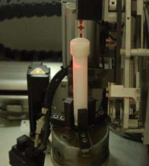
19 Cutting Before inserting mould After inserting moolds Sample moulding After sample moulding connecting to a rod for scanning Scanning Scanning for gain calibration 19
20 CT scanning Optimize scanning condition Scanning with standard specimen The area to be avoided 1. Sampling disturbance 2. Cupping error on boundary 3. Rotation axis Reconstruction Setup the sampling area Set up the gain & offset value Averaging CT values Measuring void ratio CT values void ratio relationship 20
21 Vol. fraction (Kaolinite : Bentonite) 9:1 10:0 Pre- Consolidation pressure 400kPa 350kPa 200kPa 350kPa 300kPa 250kPa 150kPa Cutting location Upper Part Upper Part Middle part Upper Part Middle part Upper Part Upper Part Middle part Upper Part Middle part Upper Part Modified CT number (MCT) Void (-CT no*10) Average ratio ( e ) MCT Area 1 Area 2 Area 3 Area
22 Contents 1. Background & motivation 2. Overview of micro X-ray CT scanning 3. Calibration of CT data 4. Experimental programme (coarse and fine soils) 5. Prediction of porosity & pore-size distribution 6. Concluding remarks 22
23 e = ( 0.005) ( CT Number) The correlation coefficient (R 2 ) and standard deviation (SD) between the void ratio and CT number is 0.91 and 0.38 respectively 23
24 Void Ratio (e) P Modified CT number (MCT) Upper part Upper Part 1 Upper Part 2 Middle part clay specimen in cylindrical box Upper Part 3 Middle Part 1 Middle Part 2 Measured values Calculated values Lower part Kaol.: Ben. = 9:1, P = 200MPa Kaol.: Ben. = 10:0, P = 250MPa Kaol.: Ben. = 10:0, P = 300MPa 24


25 Hypothesis: a voxel contains a pore in different size Void voxels are combined, thereby leading a bigger pore cv cv 25
26 Contents 1. Background & motivation 2. Overview of micro X-ray CT scanning 3. Calibration of CT data 4. Experimental programme (coarse and fine soils) 5. Prediction of porosity & pore-size distribution 6. Concluding remarks 26
27 CT imaging technique has been used to estimate pore characteristics of fine grained soils. A correlation between CT number and the porosity was established. The correlation coefficient (R 2 ) was found as 0.91, indicating a strong linear relationship between the two variables. Although in all specimens more than one of water saturated pores co-exist within a pixel, it is possible to visualize the distribution of pores and pore-structure from the CT numbers. There is a clear spatial variation of porosities within the specimens which indicates that this methodology can be used not only for rapid determination of porosity but also for pore-size distribution A formulation has been made for identifying different phases in micro-pores which will be reported shortly 27
 High power target X-ray tube (320kV) > Closed High power tube (FSS: 0.")
28 New high-capacity industrial CT facility for live testing available in KICT now which is open for any research group. Please contact us for further information Switchable hige-power multi tube type 1) High power target X-ray tube (320kV) > Closed High power tube (FSS: 0.4mm) 2) Directional target X-ray tube (225kV) > Micro focus open high power tube (FSS: 6µm) 3) Transmission target X-ray Tube (120kV) > Nano Focus Open Tube (FSS: 400nm) Dimension 3000 x 1850 x 2700 ( mm ) Weight 20,000 kg Object Loading Size: max. ø500mm x 1000mm(h) Work Table Withstand load: max. 100kg 3DCT area: ø300mm x 900mm(h) 28

29 Thank You. 29
30 Examples for spatial resolution calculation Tube Type Transmission target X-ray Tube Directional target X-ray Tube High Power target X-ray Tube Specification Voltage : 120KVp Current : 200uA Focus > 0.4um Voltage : 225KVp Current : 3.0mA Focus > 6um Voltage : 320KVp Current : 5.6mA Focus > 400um Sample size (ø mm) R FOV (ø mm) Mag(x) Spatial Resolution ( μm ³) Voxel Resolution ( μm ³) Remark FDD: 900mm FOV Max FDD: 1000mm FOV Max FDD: 1100mm 30


31 System configuration Flat DECTECTOR Worktable X-ray Tube Dimension 3000 x 1850 x 2700 ( mm ) Weight 20,000kg Power 220VAC, 50A 31
 Max voltage : 30 to 225kv Source 3) Max voltage : 30 to 120kv Focal spot size : 0.")
 Transmission target X-ray Tube > Nano")
32 X-ray source specifications Nano focus & high voltage multi tube type Source 1) Max voltage : 20 to 320kv Source 2) Max voltage : 30 to 225kv Source 3) Max voltage : 30 to 120kv Focal spot size : 0.4mm 6µm 400nm Specification of characteristic 1) High power target X-ray tube > Closed High power tube 2) Directional target X-ray tube > Micro focus open high power tube 3) Transmission target X-ray Tube > Nano Focus Open Tube 32
 x400 mm (v) Pixel")
 - 1.")
33 X-ray detector specifications Type : Digital Flat Panel Detector Radiation Energy: 40~320 kv Active Area : 400(h) x400 mm (v) Pixel Matrix : 1,024(h) x 1,024(v) Pixel Pitch : 200 μm Resolution; - 2.5lp (1x1) lp 30FPS(2x2) A/D Conversion: 16-bits (65,536 gray levels) 33
 Repetition accuracy : 0.")
34 Work table manipulator Object Loading Size: max. ø500mm x 1000mm(h) Work Table Withstand load: max. 100kg 3DCT area: ø300mm x 900mm(h) Repetition accuracy : High Precision Granite Surface Plate Anti-magnetic High shock tolerance Free from vibration 34
35 Servo axis: 6 axis X-ray Source Traverse: 900mm Detector Traverse(Top Down movement) > 900mm Detector Traverse (Left-Right) : 500mm Work table Traverse (Left-Right) : 500mm Work table Traverse (Top-Down) : 100mm Work table Rotation : 360 Work table withstand load : Max. 100kg 35

36 Radiation safety Shield Cabinet : Pb + Fe Survey window : - Pb Windows Door Safety Interlock Emergency switch Master key switch X-ray warning indication Equipment Surface of Leaking Dose 1μSv/h less than Radiation Producer Design Approval License of Radiation Producer Production Permission of Radiation Producer Production 36
HIGH RESOLUTION COMPUTED TOMOGRAPHY FOR METROLOGY
 HIGH RESOLUTION COMPUTED TOMOGRAPHY FOR METROLOGY David K. Lehmann 1, Kathleen Brockdorf 1 and Dirk Neuber 2 1 phoenix x-ray Systems + Services Inc. St. Petersburg, FL, USA 2 phoenix x-ray Systems + Services
Ch. 4 Physical Principles of CT
 Ch. 4 Physical Principles of CT CLRS 408: Intro to CT Department of Radiation Sciences Review: Why CT? Solution for radiography/tomography limitations Superimposition of structures Distinguishing between
Computed Tomography & 3D Metrology Application of the VDI/VDE Directive 2630 and Optimization of the CT system
 Computed Tomography & 3D Metrology Application of the VDI/VDE Directive 2630 and Optimization of the CT system ECNDT 2014 Prague October 6-10, 2014 Dr. Eberhard Neuser Dr. Alexander Suppes Imagination
O-ARM IMAGING SYSTEM TECHNICAL SPECIFICATION GUIDE
 IMAGING SYSTEM TECHNICAL SPECIFICATION GUIDE SYSTEM FEATURES CATEGORY PHYSICAL DIMENSIONS IMAGING MODALITY PERFORMANCE SPECIFICATION Length Width Height Weight Gantry Opening Bore Diameter Single Plane
Micro-CT Methodology Hasan Alsaid, PhD
 Micro-CT Methodology Hasan Alsaid, PhD Preclinical & Translational Imaging LAS, PTS, GlaxoSmithKline 20 April 2015 Provide basic understanding of technical aspects of the micro-ct Statement: All procedures
Design and performance characteristics of a Cone Beam CT system for Leksell Gamma Knife Icon
 Design and performance characteristics of a Cone Beam CT system for Leksell Gamma Knife Icon WHITE PAPER Introduction Introducing an image guidance system based on Cone Beam CT (CBCT) and a mask immobilization
Recognition and Measurement of Small Defects in ICT Testing
 19 th World Conference on Non-Destructive Testing 2016 Recognition and Measurement of Small Defects in ICT Testing Guo ZHIMIN, Ni PEIJUN, Zhang WEIGUO, Qi ZICHENG Inner Mongolia Metallic Materials Research
Deformation of granular texture media studied by X-ray CT & 3D DIC at the continuous and microstructure scales
 Deformation of granular texture media studied by X-ray CT & 3D DIC at the continuous and microstructure scales N. Lenoir, S.A. Hall, J. Desrues, G. Viggiani and P. Bésuelle (Laboratoire 3S-R) Michel Bornert
X-ray tomographic study of wetting bentonite
 UNIVERSITY OF JYVÄSKYLÄ X-ray tomographic study of wetting bentonite Tero Harjupatana Department of Physics, University of Jyväskylä BOA seminar 19.8.2014 Goal To develop and apply experimental techniques
Digital Image Processing
 Digital Image Processing SPECIAL TOPICS CT IMAGES Hamid R. Rabiee Fall 2015 What is an image? 2 Are images only about visual concepts? We ve already seen that there are other kinds of image. In this lecture
HIGH-SPEED THEE-DIMENSIONAL TOMOGRAPHIC IMAGING OF FRAGMENTS AND PRECISE STATISTICS FROM AN AUTOMATED ANALYSIS
 23 RD INTERNATIONAL SYMPOSIUM ON BALLISTICS TARRAGONA, SPAIN 16-20 APRIL 2007 HIGH-SPEED THEE-DIMENSIONAL TOMOGRAPHIC IMAGING OF FRAGMENTS AND PRECISE STATISTICS FROM AN AUTOMATED ANALYSIS P. Helberg 1,
3D X-ray Laminography with CMOS Image Sensor Using a Projection Method for Reconstruction of Arbitrary Cross-sectional Images
 Ke Engineering Materials Vols. 270-273 (2004) pp. 192-197 online at http://www.scientific.net (2004) Trans Tech Publications, Switzerland Online available since 2004/08/15 Citation & Copright (to be inserted
Supplementary Information
 Supplementary Information Interferometric scattering microscopy with polarization-selective dual detection scheme: Capturing the orientational information of anisotropic nanometric objects Il-Buem Lee
Coordinate Measuring Machines with Computed Tomography
 Always a Step Ahead with Quality Coordinate Measuring Machines with Computed Tomography Multisensor Coordinate Measuring Machines with Computed Tomography Computed Tomography in Coordinate Measuring Machines
Developments in Dimensional Metrology in X-ray Computed Tomography at NPL
 Developments in Dimensional Metrology in X-ray Computed Tomography at NPL Wenjuan Sun and Stephen Brown 10 th May 2016 1 Possible factors influencing XCT measurements Components Influencing variables Possible
SYSTEM LINEARITY LAB MANUAL: 2 Modifications for P551 Fall 2013 Medical Physics Laboratory
 SYSTEM LINEARITY LAB MANUAL: 2 Modifications for P551 Fall 2013 Medical Physics Laboratory Introduction In this lab exercise, you will investigate the linearity of the DeskCAT scanner by making measurements
TEP Hounsfield units. Related topics Attenuation coefficient, Hounsfield units
 Hounsfield units TEP Related topics Attenuation coefficient, Hounsfield units Principle Depending on the type of CT scanner and the settings, the result of a CT scan of the same material can be different
DEVELOPMENT OF CONE BEAM TOMOGRAPHIC RECONSTRUCTION SOFTWARE MODULE
 Rajesh et al. : Proceedings of the National Seminar & Exhibition on Non-Destructive Evaluation DEVELOPMENT OF CONE BEAM TOMOGRAPHIC RECONSTRUCTION SOFTWARE MODULE Rajesh V Acharya, Umesh Kumar, Gursharan
CT Systems and their standards
 CT Systems and their standards Stephen Brown Engineering Measurement 11 th April 2012 Industrial X-ray computed tomography: The future of co-ordinate metrology? Burleigh Court, Loughborough University
CT Reconstruction with Good-Orientation and Layer Separation for Multilayer Objects
 17th World Conference on Nondestructive Testing, 25-28 Oct 2008, Shanghai, China CT Reconstruction with Good-Orientation and Layer Separation for Multilayer Objects Tong LIU 1, Brian Stephan WONG 2, Tai
Best inspection system for after reworking of the BGA, and other electronic parts.
 MSX1000HR X Ray Inspection System High resolution micro-focus system, by new developed X ray generator. Easy and safety operation system, by the original radiation prevention cabinet. Best inspection system
The Electrochemical Innovation Lab X-ray Suite: from macro- to nano-ct
 The Electrochemical Innovation Lab X-ray Suite: from macro- to nano-ct Dr. Francesco Iacoviello, Toby Neville & the Electrochemical Innovation Lab f.iacoviello@ucl.ac.uk MANIFEST - 2017 November 10 th,
Digital Volume Correlation for Materials Characterization
 19 th World Conference on Non-Destructive Testing 2016 Digital Volume Correlation for Materials Characterization Enrico QUINTANA, Phillip REU, Edward JIMENEZ, Kyle THOMPSON, Sharlotte KRAMER Sandia National
Digital Laminography and Computed Tomography with 600 kv for Aerospace Applications
 4th International Symposium on NDT in Aerospace 2012 - Tu.3.A.1 Digital Laminography and Computed Tomography with 600 kv for Aerospace Applications Malte KURFISS 1, Gerd STRECKENBACH 2 1 YXLON International
Image Acquisition Systems
 Image Acquisition Systems Goals and Terminology Conventional Radiography Axial Tomography Computer Axial Tomography (CAT) Magnetic Resonance Imaging (MRI) PET, SPECT Ultrasound Microscopy Imaging ITCS
Advanced Computed Tomography System for the Inspection of Large Aluminium Car Bodies
 ECNDT 2006 - Th.3.4.2 Advanced Computed Tomography System for the Inspection of Large Aluminium Car Bodies M. SIMON, I. TISEANU, C. SAUERWEIN Hans WÄLISCHMILLER, Meersburg, Germany M. SINDEL, M. BRODMANN,
18th World Conference on Nondestructive Testing, April 2012, Durban, South Africa
 18th World Conference on Nondestructive Testing, 16-20 April 2012, Durban, South Africa TOWARDS ESTABLISHMENT OF STANDARDIZED PRACTICE FOR ASSESSMENT OF SPATIAL RESOLUTION AND CONTRAST OF INTERNATIONAL
Chapter 3. Experimental Procedure
 Chapter 3 Experimental Procedure 33 3.1 Burner Systems Startup 3.1.1 Instrumentation power up The instrumentation of the burner including the PC need to be turned on, in order to provide safe ignition
DUE to beam polychromacity in CT and the energy dependence
 1 Empirical Water Precorrection for Cone-Beam Computed Tomography Katia Sourbelle, Marc Kachelrieß, Member, IEEE, and Willi A. Kalender Abstract We propose an algorithm to correct for the cupping artifact
C a t p h a n / T h e P h a n t o m L a b o r a t o r y
 C a t p h a n 5 0 0 / 6 0 0 T h e P h a n t o m L a b o r a t o r y C a t p h a n 5 0 0 / 6 0 0 Internationally recognized for measuring the maximum obtainable performance of axial, spiral and multi-slice
TOMOGRAPHIC RECONSTRUCTIONS AND PREDICTIONS OF RADIAL VOID DISTRIBUTION IN BWR FUEL BUNDLE WITH PART- LENGTH RODS
 TOMOGRAPHIC RECONSTRUCTIONS AND PREDICTIONS OF RADIAL VOID DISTRIBUTION IN BWR FUEL BUNDLE WITH PART- LENGTH RODS M. Ahnesjö *, P. Andersson Department of Physics and Astronomy Uppsala University, 75120,
Performance Evaluation of 3-Axis Scanner Automated For Industrial Gamma- Ray Computed Tomography
 National Seminar & Exhibition on Non-Destructive Evaluation, NDE 2014, Pune, December 4-6, 2014 (NDE-India 2014) Vol.20 No.6 (June 2015) - The e-journal of Nondestructive Testing - ISSN 1435-4934 www.ndt.net/?id=17822
Optiv CT160 Accurate measurement for every detail. Computed Tomography System
 Optiv CT160 Accurate measurement for every detail Computed Tomography System Computed Tomography CT Technology. New prospects for metrology. Computed tomography (CT), a technology with unique advantages,
CLASS HOURS: 4 CREDIT HOURS: 4 LABORATORY HOURS: 0
 Revised 10/10 COURSE SYLLABUS TM 220 COMPUTED TOMOGRAPHY PHYSICS CLASS HOURS: 4 CREDIT HOURS: 4 LABORATORY HOURS: 0 CATALOG COURSE DESCRIPTION: This course is one of a three course set in whole body Computed
Z-MOTION. Universal Digital Radiographic System Z-MOTION. Control-X Medical CONTROL-X MEDICAL
 Control-X Medical Z-MOTION Compact design, low ceiling height requirement Motorized and manual movement capability Wide motion / SID range Best-in-class image quality Flexible connectivity to PACS systems
Advanced Non-Destructive Testing by High Resolution Computed Tomography for 3D analysis of Automotive Components
 Advanced Non-Destructive Testing by High Resolution Computed Tomography for 3D analysis of Automotive Components J. Luebbehuesen GE Sensing & Inspection Technologies GmbH, phoenix x-ray, Niels-Bohr-Str.
Equipment Specification
 MULTISLICE CT SCANNER ( 16 Slices ) Merk : Hitachi Japan Model : SUPRIA 5 MHU Price : Rp 6.512.360.215,27 No Equipment Specification 1 2 3 Scanner Gantry Object for scanning : Whole body including head
Digital Core study of Wanaea and Perseus Core Fragments:
 Digital Core study of Wanaea and Perseus Core Fragments: Summary for Woodside Energy Mark A. Knackstedt,2, A. Ghous 2, C. H. Arns, H. Averdunk, F. Bauget, A. Sakellariou, T.J. Senden, A.P. Sheppard,R.
Traceable 3D X-Ray Measurements ZEISS METROTOM
 20 Traceable 3D X-Ray Measurements With a computer tomograph, you can successfully perform measuring and inspection jobs yourself with only one X-ray scan. The standard acceptance test, the precision engineering
Introduction to Biomedical Imaging
 Alejandro Frangi, PhD Computational Imaging Lab Department of Information & Communication Technology Pompeu Fabra University www.cilab.upf.edu X-ray Projection Imaging Computed Tomography Digital X-ray
Japan Foundry Society, Inc. Application of Recent X-ray CT Technology to Investment Casting field. Kouichi Inagaki ICC / IHI Corporation
 Japan Foundry Society, Inc. Application of Recent X-ray CT Technology to Investment Casting field Kouichi Inagaki ICC / IHI Corporation 13 th WORLD CONFERENCE ON INVESTMENT CASTING Paper: T3 Copyright
CIVA Computed Tomography Modeling
 CIVA Computed Tomography Modeling R. FERNANDEZ, EXTENDE, France S. LEGOUPIL, M. COSTIN, D. TISSEUR, A. LEVEQUE, CEA-LIST, France page 1 Summary Context From CIVA RT to CIVA CT Reconstruction Methods Applications
A U T O C O L L I M A T O R S
 Printed in Germany 229 900 E 04/07 E l e c t r o n i c α A U T O C O L L I M A T O R S Measure With Precision MÖLLER-WEDEL OPTICAL GmbH Rosengarten 10 D-22880 Wedel Tel : +49-41 03-9 37 76 10 Fax: +49-41
A Global Laser Brand. Versatile Module
 A Global Laser Brand Versatile Module The Versatile Module The VM (Versatile Module) from Imatronic provides a high quality and cost effect OEM solution to a wide range of applications including Machine
Industrial Computed Tomography Innovations
 GE Inspection Technologies Industrial Computed Tomography Innovations Premium performance for premium quality and speed. gemeasurement.com/ct Premium CT technologies. Faster than ever before. Every industrial
WAVELENGTH MANAGEMENT
 BEAM DIAGNOS TICS SPECIAL PRODUCTS OEM DETECTORS THZ DETECTORS PHOTO DETECTORS HIGH POWER SOLUTIONS POWER DETECTORS ENERGY DETECTORS MONITORS Camera Accessories WAVELENGTH MANAGEMENT UV CONVERTERS UV Converters
SUPPLEMENTARY INFORMATION
 Supplementary Information Compact spectrometer based on a disordered photonic chip Brandon Redding, Seng Fatt Liew, Raktim Sarma, Hui Cao* Department of Applied Physics, Yale University, New Haven, CT
WAVELENGTH MANAGEMENT
 Camera Accessories WAVELENGTH MANAGEMENT UV CONVERTERS UV Converters take advantage of a phenomenon called fluorescence to extend the performance range of the Beamage beam profiling camera to ultraviolet
Aggregates Geometric Parameters
 Aggregates Geometric Parameters On-Line or Lab Measurement of Size and Shapes by 3D Image Analysis Terry Stauffer Application Note SL-AN-48 Revision A Provided By: Microtrac Particle Characterization Solutions
Joint ICTP-TWAS Workshop on Portable X-ray Analytical Instruments for Cultural Heritage. 29 April - 3 May, 2013
 2455-5 Joint ICTP-TWAS Workshop on Portable X-ray Analytical Instruments for Cultural Heritage 29 April - 3 May, 2013 Lecture NoteBasic principles of X-ray Computed Tomography Diego Dreossi Elettra, Trieste
Spiral CT. Protocol Optimization & Quality Assurance. Ge Wang, Ph.D. Department of Radiology University of Iowa Iowa City, Iowa 52242, USA
 Spiral CT Protocol Optimization & Quality Assurance Ge Wang, Ph.D. Department of Radiology University of Iowa Iowa City, Iowa 52242, USA Spiral CT Protocol Optimization & Quality Assurance Protocol optimization
2011 Optical Science & Engineering PhD Qualifying Examination Optical Sciences Track: Advanced Optics Time allowed: 90 minutes
 2011 Optical Science & Engineering PhD Qualifying Examination Optical Sciences Track: Advanced Optics Time allowed: 90 minutes Answer all four questions. All questions count equally. 3(a) A linearly polarized
arxiv: v1 [physics.ins-det] 13 Jan 2015
![arxiv: v1 [physics.ins-det] 13 Jan 2015](/thumbs/89/99044322.jpg "arxiv: v1 [physics.ins-det] 13 Jan 2015") The Assembly of the Belle II TOP Counter Boqun Wang, On behalf of the Belle II PID Group Department of Physics, University of Cincinnati, Cincinnati, OH, USA University of Cincinnati preprint UCHEP-14-01
The Assembly of the Belle II TOP Counter Boqun Wang, On behalf of the Belle II PID Group Department of Physics, University of Cincinnati, Cincinnati, OH, USA University of Cincinnati preprint UCHEP-14-01
Radiology. Marta Anguiano Millán. Departamento de Física Atómica, Molecular y Nuclear Facultad de Ciencias. Universidad de Granada
 Departamento de Física Atómica, Molecular y Nuclear Facultad de Ciencias. Universidad de Granada Overview Introduction Overview Introduction Tecniques of imaging in Overview Introduction Tecniques of imaging
Digital Scatter Removal in Mammography to enable Patient Dose Reduction
 Digital Scatter Removal in Mammography to enable Patient Dose Reduction Mary Cocker Radiation Physics and Protection Oxford University Hospitals NHS Trust Chris Tromans, Mike Brady University of Oxford
Shielding factors for traditional safety glasses
 Shielding factors for traditional safety glasses Malcolm McEwen, Hong Shen and Ernesto Mainegra-Hing Ionizing Radiation Standards, National Research Council Canada Alan DuSautoy, Radiation and Health Sciences
SUPPLEMENTARY INFORMATION
 SUPPLEMENTARY INFORMATION doi:10.1038/nature10934 Supplementary Methods Mathematical implementation of the EST method. The EST method begins with padding each projection with zeros (that is, embedding
3/27/2012 WHY SPECT / CT? SPECT / CT Basic Principles. Advantages of SPECT. Advantages of CT. Dr John C. Dickson, Principal Physicist UCLH
 3/27/212 Advantages of SPECT SPECT / CT Basic Principles Dr John C. Dickson, Principal Physicist UCLH Institute of Nuclear Medicine, University College London Hospitals and University College London john.dickson@uclh.nhs.uk
Multi-slice CT Image Reconstruction Jiang Hsieh, Ph.D.
 Multi-slice CT Image Reconstruction Jiang Hsieh, Ph.D. Applied Science Laboratory, GE Healthcare Technologies 1 Image Generation Reconstruction of images from projections. textbook reconstruction advanced
How does the ROI affect the thresholding?
 How does the ROI affect the thresholding? Micro-computed tomography can be applied for the visualization of the inner structure of a material or biological tissue in a non-destructive manner. Besides visualization,
Corso di laurea in Fisica A.A Fisica Medica 4 TC
 Corso di laurea in Fisica A.A. 2007-2008 Fisica Medica 4 TC Computed Tomography Principles 1. Projection measurement 2. Scanner systems 3. Scanning modes Basic Tomographic Principle The internal structure
Using X-Ray Micro Tomography to assess the quality of Packaging Foil
 Using X-Ray Micro Tomography to assess the quality of Packaging Foil Martin Koster 1, Gerard van Dalen 2, Robert Hoeve 3 1 Unilever Research 2 Unilever Research 3 Unilever Research, Olivier van Noortlaaan
Quality control phantoms and protocol for a tomography system
 Quality control phantoms and protocol for a tomography system Lucía Franco 1 1 CT AIMEN, C/Relva 27A O Porriño Pontevedra, Spain, lfranco@aimen.es Abstract Tomography systems for non-destructive testing
SUPPLEMENTARY INFORMATION
 doi:10.1038/nature12009 Supplementary Figure 1. Experimental tilt series of 104 projections with a tilt range of ±72.6 and equal slope increments, acquired from a Pt nanoparticle using HAADF- STEM (energy:
XRADIA microxct Manual
 XRADIA microxct Manual Multiscale CT Lab Table of Contents 1. Introduction and Basics 1.1 Instrument Parts 1.2 Powering up the system 1.3 Preparing your sample 2. TXM Controller 2.1 Starting up 2.2 Finding
LABORATORY SYSTEM FOR X-RAY NANOTOMOGRAPHY
 79 LABORATORY SYSTEM FOR X-RAY NANOTOMOGRAPHY Alexander Sasov, SkyScan, Vluchtenburgstraat 3, Aartselaar B2630, Belgium, www.skyscan.be. ABSTRACT Using advanced X-ray technologies and X-ray scattering
Computer-Tomography II: Image reconstruction and applications
 Computer-Tomography II: Image reconstruction and applications Prof. Dr. U. Oelfke DKFZ Heidelberg Department of Medical Physics (E040) Im Neuenheimer Feld 280 69120 Heidelberg, Germany u.oelfke@dkfz.de
Phase-Contrast Imaging and Tomography at 60 kev using a Conventional X-ray Tube
 Phase-Contrast Imaging and Tomography at 60 kev using a Conventional X-ray Tube T. Donath* a, F. Pfeiffer a,b, O. Bunk a, W. Groot a, M. Bednarzik a, C. Grünzweig a, E. Hempel c, S. Popescu c, M. Hoheisel
Ion Beam Profiling Using a Novel Electronic Imaging Detector
 Ion Beam Profiling Using a Novel Electronic Imaging Detector *Bruce N Laprade and Richard A Prunier BURLE Electro-Optics Sturbridge MA Paper 1700-2400 Presented at The 2004 Pittsburgh Conference March
C-Rover Transmissometer
 C-Rover Transmissometer User s Guide WET Labs, Inc. PO Box 518 Philomath, OR 97370 (541) 929-5650 www.wetlabs.com C-Rover User s Guide (crover) Revision C 27 March 2007 C-Rover Warranty This unit is guaranteed
Combining Analytical and Monte Carlo Modelling for Industrial Radiology
 19 th World Conference on Non-Destructive Testing 2016 Combining Analytical and Monte Carlo Modelling for Industrial Radiology Carsten BELLON, Gerd-Rüdiger JAENISCH, Andreas DERESCH BAM Bundesanstalt für
Advanced Reconstruction Techniques Applied to an On-Site CT System
 2nd International Symposium on NDT in Aerospace 2010 - We.1.A.4 Advanced Reconstruction Techniques Applied to an On-Site CT System Jonathan HESS, Markus EBERHORN, Markus HOFMANN, Maik LUXA Fraunhofer Development
Medical Physics Research Center, Mashhad University of Medical Sciences, Mashhad, Iran.
 DXRaySMCS First User Friendly Interface Developed for Prediction of Diagnostic Radiology X-Ray Spectra Produced by Monte Carlo (MCNP-4C) Simulation in Iran M.T. Bahreyni Toosi a*, H. Moradi b, H. Zare
BME I5000: Biomedical Imaging
 1 Lucas Parra, CCNY BME I5000: Biomedical Imaging Lecture 4 Computed Tomography Lucas C. Parra, parra@ccny.cuny.edu some slides inspired by lecture notes of Andreas H. Hilscher at Columbia University.
X-ray MicroCT in Conjunction with Other Techniques for Core Analysis
 X-ray MicroCT in Conjunction with Other Techniques for Core Analysis I.V. Yakimchuk 1, A.S. Denisenko 1, B.D. Sharchilev 1, and I.A. Varfolomeev 1,2 1 Schlumberger, 119285, 13 Pudovkina str., Moscow, Russia,
Application of 450 kv Computed Tomography to Engine Blocks with Steel Liners
 Application of 450 kv Computed Tomography to Engine Blocks with Steel Liners Charles R. Smith, Kevin Holt BIR, Inc. Uwe Bischoff, Bernd Georgi, Ferdinand Hansen, Frank Jeltsch Volkswagen Commercial Vehicles
LIMO Line Laser System - PEX High Power Diode Laser System for Industrial Applications
 General Description: Flat Panel Display The laser system is engineered to generate a homogeneous line of 80 mm x 0.2 mm. Componets: - 9x Laser modules - 9x Fibres - Beam Shaping Module - High power laser
Comparison of Scatter Correction Methods for CBCT. Author(s): Suri, Roland E.; Virshup, Gary; Kaissl, Wolfgang; Zurkirchen, Luis
: Suri, Roland E.; Virshup, Gary; Kaissl, Wolfgang; Zurkirchen, Luis") Research Collection Working Paper Comparison of Scatter Correction Methods for CBCT Author(s): Suri, Roland E.; Virshup, Gary; Kaissl, Wolfgang; Zurkirchen, Luis Publication Date: 2010 Permanent Link:
Research Collection Working Paper Comparison of Scatter Correction Methods for CBCT Author(s): Suri, Roland E.; Virshup, Gary; Kaissl, Wolfgang; Zurkirchen, Luis Publication Date: 2010 Permanent Link:
Contour LS-K Optical Surface Profiler
 Contour LS-K Optical Surface Profiler LightSpeed Focus Variation Provides High-Speed Metrology without Compromise Innovation with Integrity Optical & Stylus Metrology Deeper Understanding More Quickly
3D Measurement of Transparent Vessel and Submerged Object Using Laser Range Finder
 3D Measurement of Transparent Vessel and Submerged Object Using Laser Range Finder Hirotoshi Ibe Graduate School of Science and Technology, Shizuoka University 3-5-1 Johoku, Naka-ku, Hamamatsu-shi, Shizuoka
X-rays see all X-ray computed microtomography (µct) a novel technique available at CERN for material and metrological inspection
 a novel technique available at CERN for material and metrological inspection") X-rays see all X-ray computed microtomography (µct) a novel technique available at CERN for material and metrological inspection Mariusz Jedrychowski EN/MME-MM Introduction of new technique at CERN 12/12/2017
X-rays see all X-ray computed microtomography (µct) a novel technique available at CERN for material and metrological inspection Mariusz Jedrychowski EN/MME-MM Introduction of new technique at CERN 12/12/2017
ksa MOS Ultra-Scan Performance Test Data
 ksa MOS Ultra-Scan Performance Test Data Introduction: ksa MOS Ultra Scan 200mm Patterned Silicon Wafers The ksa MOS Ultra Scan is a flexible, highresolution scanning curvature and tilt-measurement system.
Displacement in sand under triaxial compression by tracking soil particles on X-ray CT data
 Soils and Foundations 212;52(2):312 32 The Japanese Geotechnical Society Soils and Foundations www.sciencedirect.com journal homepage: www.elsevier.com/locate/sandf Displacement in sand under triaxial
Complete 3D measurement solution
 Complete 3D measurement solution Complete access The S neox Five Axis 3D optical profiler combines a high-accuracy rotational module with the advanced inspection and analysis capabilities of the S neox
MEDICAL EQUIPMENT: COMPUTED TOMOGRAPHY. Prof. Yasser Mostafa Kadah
 MEDICAL EQUIPMENT: COMPUTED TOMOGRAPHY Prof. Yasser Mostafa Kadah www.k-space.org Recommended Textbook X-Ray Computed Tomography in Biomedical Engineering, by Robert Cierniak, Springer, 211 Computed Tomography
The new generation of industrial computed tomography. The Desktop CT exact S
 The new generation of industrial computed tomography The Desktop CT S Volume scanning technology Innovation with a family tradition Founded in 1968, the family-owned, WEN- ZEL Metrology Group is one of
A new Concept for High-Speed atline and inlinect for up to 100% Mass Production Process Control
 18th World Conference on Nondestructive Testing, 16-20 April 2012, Durban, South Africa A new Concept for High-Speed atline and inlinect for up to 100% Mass Production Process Control Oliver BRUNKE 1,
Insights into EMC Chamber Design:
 Insights into EMC Chamber Design: How to achieve an optimized chamber for accurate EMC Measurements Zubiao Xiong, PhD zubiao.xiong@ets-lindgren.com November 16, 2017 EMC Compliance Testing Emission (Disturbance)
Towards a robust model of planetary thermal profiles
 Towards a robust model of planetary thermal profiles RT Equation: General Solution: RT Equation: General Solution: Extinction coefficient Emission coefficient How would you express the Source function
High Resolution Phased Array Imaging using the Total Focusing Method
 High Resolution Phased Array Imaging using the Total Focusing Method S. Kierspel, Wolfram A. Karl Deutsch, Helge Rast, Philippe Benoist 1, Venkat A 2 KARL DEUTSCH Pruef- und Messgeraetebau GmbH + Co KG
ML reconstruction for CT
 ML reconstruction for CT derivation of MLTR rigid motion correction resolution modeling polychromatic ML model dual energy ML model Bruno De Man, Katrien Van Slambrouck, Maarten Depypere, Frederik Maes,
Micro-CT in geosciences: Getting the inside story. Wesley De Boever
 Micro-CT in geosciences: Getting the inside story Wesley De Boever November 24, 2016 Bruker microct Micro-CT scanner manufacturer Life science and material science Hardware and software Headquarters in
THREE-DIMENSIONA L ELECTRON MICROSCOP Y OF MACROMOLECULAR ASSEMBLIE S. Visualization of Biological Molecules in Their Native Stat e.
 THREE-DIMENSIONA L ELECTRON MICROSCOP Y OF MACROMOLECULAR ASSEMBLIE S Visualization of Biological Molecules in Their Native Stat e Joachim Frank CHAPTER 1 Introduction 1 1 The Electron Microscope and
MEDICAL IMAGING 2nd Part Computed Tomography
 MEDICAL IMAGING 2nd Part Computed Tomography Introduction 2 In the last 30 years X-ray Computed Tomography development produced a great change in the role of diagnostic imaging in medicine. In convetional
Advanced materials research using the Real-Time 3D Analytical FIB-SEM 'NX9000'
 SCIENTIFIC INSTRUMENT NEWS 2017 Vol. 9 SEPTEMBER Technical magazine of Electron Microscope and Analytical Instruments. Technical Explanation Advanced materials research using the Real-Time 3D Analytical
VXRE Reconstruction Software Manual
 VXRE Reconstruction Software Manual Version 1.7.8 3D INDUSTRIAL IMAGING 3D Industrial Imaging Co.,Ltd. Address :#413 Institute of Computer Technology, Seoul National University, Daehak-dong, Gwanak-gu,
Empirical cupping correction: A first-order raw data precorrection for cone-beam computed tomography
 Empirical cupping correction: A first-order raw data precorrection for cone-beam computed tomography Marc Kachelrieß, a Katia Sourbelle, and Willi A. Kalender Institute of Medical Physics, University of
Complete Barrel Measuring and Inspection System. PS Series. User s manual
 Complete Barrel Measuring and Inspection System PS Series User s manual SAFETY PRECAUTIONS... 3 ELECTROMAGNETIC COMPATIBILITY... 3 LASER SAFETY... 3 GENERAL INFORMATION... 3 BASIC DATA AND PERFORMANCE
System Optimization and Patient Translational Motion Correction for Reduction of Artifacts in a Fan-Beam CT Scanner
 Wright State University CORE Scholar Browse all Theses and Dissertations Theses and Dissertations 2012 System Optimization and Patient Translational Motion Correction for Reduction of Artifacts in a Fan-Beam
RADIOLOGY AND DIAGNOSTIC IMAGING
 Day 2 part 2 RADIOLOGY AND DIAGNOSTIC IMAGING Dr hab. Zbigniew Serafin, MD, PhD serafin@cm.umk.pl 2 3 4 5 CT technique CT technique 6 CT system Kanal K: RSNA/AAPM web module: CT Systems & CT Image Quality