Lecture 7 Fault Simulation
|
|
|
- Dina Lambert
- 5 years ago
- Views:
Transcription
1 Lecture 7 Fault Simulation Problem and motivation Fault simulation algorithms Serial Parallel Deductive Concurrent Random Fault Sampling Summary Copyright 2, Agrawal & Bushnell VLSI Test: Lecture 7
2 Problem and Motivation Fault simulation Problem: Given A circuit A sequence of test vectors A fault model Determine Fault coverage - fraction (or percentage) of modeled faults detected by test vectors Set of undetected faults Motivation Determine test quality and in turn product quality Find undetected fault targets to improve tests Copyright 2, Agrawal & Bushnell VLSI Test: Lecture 7 2
3 Fault simulator in a VLSI Design Process Verified design netlist Verification input stimuli Fault simulator Test vectors Modeled fault list Remove tested faults Test compactor Delete vectors Fault coverage? Low Adequate Stop Test generator Add vectors Copyright 2, Agrawal & Bushnell VLSI Test: Lecture 7 3
4 Fault Simulation Scenario Circuit model: mixed-level Mostly logic with some switch-level for highimpedance (Z) and bidirectional signals High-level models (memory, etc.) with pin faults Signal states: logic Timing: Two (, ) or three (,, X) states for purely Boolean logic circuits Four states (,, X, Z) for sequential MOS circuits Zero-delay for combinational and synchronous circuits Mostly unit-delay for circuits with feedback Copyright 2, Agrawal & Bushnell VLSI Test: Lecture 7 4
5 Fault Simulation Scenario (continued) Faults: Mostly single stuck-at faults Sometimes stuck-open, transition, and path-delay faults; analog circuit fault simulators are not yet in common use Equivalence fault collapsing of single stuck-at faults Fault-dropping -- a fault once detected is dropped from consideration as more vectors are simulated; fault-dropping may be suppressed for diagnosis Fault sampling -- a random sample of faults is simulated when the circuit is large Copyright 2, Agrawal & Bushnell VLSI Test: Lecture 7 5
6 Fault Simulation Algorithms Serial Parallel Deductive Concurrent Differential Copyright 2, Agrawal & Bushnell VLSI Test: Lecture 7 6
7 Serial Algorithm Algorithm: Simulate fault-free circuit and save responses. Repeat following steps for each fault in the fault list: Modify netlist by injecting one fault Simulate modified netlist, vector by vector, comparing responses with saved responses If response differs, report fault detection and suspend simulation of remaining vectors Advantages: Easy to implement; needs only a true-value simulator, less memory Most faults, including analog faults, can be simulated Copyright 2, Agrawal & Bushnell VLSI Test: Lecture 7 7
8 Serial Algorithm (Cont.) Disadvantage: Much repeated computation; CPU time prohibitive for VLSI circuits Alternative: Simulate many faults together Test vectors Fault-free circuit Comparator f detected? Circuit with fault f Comparator f2 detected? Circuit with fault f2 Comparator fn detected? Circuit with fault fn Copyright 2, Agrawal & Bushnell VLSI Test: Lecture 7 8
9 Copyright 2, Agrawal & Bushnell VLSI Test: Lecture 7 9
10 Parallel Fault Simulation Compiled-code method; best with twostates (,) Exploits inherent bit-parallelism of logic operations on computer words Storage: one word per line for two-state simulation Multi-pass simulation: Each pass simulates w- new faults, where w is the machine word length Speed up over serial method ~ w- Not suitable for circuits with timing-critical and non-boolean logic F9 F8 F7 F6 F5 F4 F3 F2 F F F Copyright 2, Agrawal & Bushnell VLSI Test: Lecture 7
11 Parallel Fault Sim. Example Bit : fault-free circuit Bit : circuit with c s-a- Bit 2: circuit with f s-a- a b c s-a- e c s-a- detected g d f s-a- Copyright 2, Agrawal & Bushnell VLSI Test: Lecture 7


12 Fault Injection for parallels fault simulati ٦ ٧week Fault-Tolerant Digital System Design ١٢
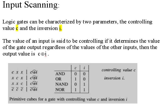
13 Copyright 2, Agrawal & Bushnell VLSI Test: Lecture 7 3
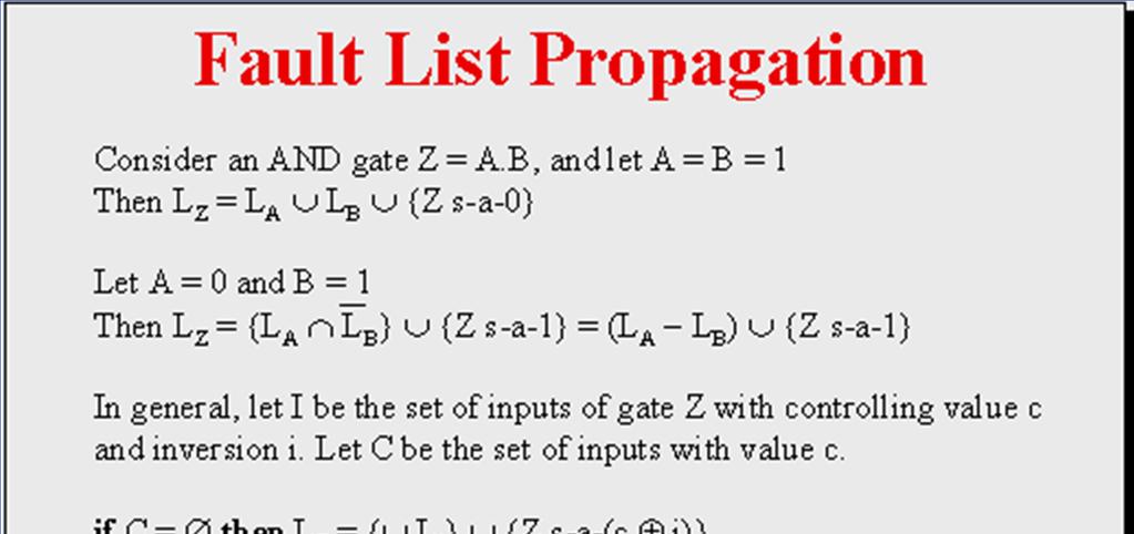
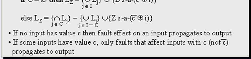
14 Deductive Fault Simulation One-pass simulation Each line k contains a list L k of faults detectable on k Following true-value simulation of each vector, fault lists of all gate output lines are updated using settheoretic rules, signal values, and gate input fault lists PO fault lists provide detection data At each of the primary inputs generate the list of faults that can be detected by the test vector Use these lists to generate the lists at other nodes by appropriate operations on these lists Limitations: Set-theoretic rules difficult to derive for non- Boolean gates Gate delays are difficult to use Copyright 2, Agrawal & Bushnell VLSI Test: Lecture 7 4

15 Fault Lists In deductive Fault lists propagation In deductive fault simulator c a,c b,c a,b,c L ٦ ٧week B Is the set of faults not in L Fault-Tolerant Digital System Design B ١٥
16 Deductive Fault Sim. Example Notation: L k is fault list for line k k n is s-a-n fault on line k a b {a } L e = L a U L c U {e } = {a, b, c, e } {b, c } e {b } c d {b, d } f {b, d, f } g L g = (L e L f ) U {g } = {a, c, e, g } U Faults detected by the input vector Copyright 2, Agrawal & Bushnell VLSI Test: Lecture 7 6


17 Two valued Deductive Simulation or L ٦ ٧week B Is the set of faults not in L Fault-Tolerant Digital System Design B ١٧

18 ٦ ٧week Fault-Tolerant Digital System Design ١٨

19 ٤Week Fault-Tolerant System Design ١٩
20 Example 5. Example 5. Test Vector ٦ ٧week Fault-Tolerant Digital System Design ٢٠

21 ٦ ٧week Fault-Tolerant Digital System Design ٢١
22 Deductive Fault Simulation (example) La = {a} Lb = {b} Lc = {c} Ld = {d} Le = {e} a i b c d e f g h Lfp = Lb Lc = {c} Lf = {c, f} Lgp = (Ld Le ) = {d} Lg = {d, g} Lhp = (Lf Lg), Lhp = Lh = {h} Lip = La Lh, Lip = {h} Li = {h, i}
23 Deductive Fault Simulation (example contd.) La = {a} Lb = {b} Lc = {c} Ld = {d} Le = {e} a i b c d e f g h Lfp = Lb Lc = { b, c} Lf = {b, c, f} Lgp = (Ld Le ) = {d} Lg = {d, g} Lhp = (Lf Lg) ={ d, g } Lhp = {d,g}, Lh = {d,g,h} Lip = La Lh, Lip = {d, g,h} Li = {d, g, h, i}
24 Copyright 2, Agrawal & Bushnell VLSI Test: Lecture 7 24
25 Concurrent Fault Simulation Event-driven simulation of fault-free circuit and only those parts of the faulty circuit that differ in signal states from the fault-free circuit. A list per gate containing copies of the gate from all faulty circuits in which this gate differs. List element contains fault ID, gate input and output values and internal states, if any. All events of fault-free and all faulty circuits are implicitly simulated. Faults can be simulated in any modeling style or detail supported in true-value simulation (offers most flexibility.) Faster than other methods, but uses most memory. Copyright 2, Agrawal & Bushnell VLSI Test: Lecture 7 25
26 Copyright 2, Agrawal & Bushnell VLSI Test: Lecture 7 26 Conc. Fault Sim. Example Conc. Fault Sim. Example a b c d e f g a b c e a b b c e d d g f f
 In")


27 Fault-Lists (Bad-gates) In concurrent Fault Simulation L g ={a,c,e,g } ٦ ٧week Fault-Tolerant Digital System Design ٢٧
28 Event processing and convergence in concurrent fault simula The processing of the ( ) good-event at a is not complete ٦ ٧week Fault-Tolerant Digital System Design ٢٨

29 Complete fault-lists (bad gates) Bade-gate divergence in concurrent fault simulation ٦ ٧week Fault-Tolerant Digital System Design ٢٩
30 Copyright 2, Agrawal & Bushnell VLSI Test: Lecture 7 3


31 Copyright 2, Agrawal & Bushnell VLSI Test: Lecture 7 3
32 Copyright 2, Agrawal & Bushnell VLSI Test: Lecture 7 32
33 ٦ ٧week Fault-Tolerant Digital System Design ٣٣


34 Critical Path Tracing ٦ ٧week Fault-Tolerant Digital System Design ٣٤


35 Example of Critical path tracing in fanout-free ٦ ٧week Fault-Tolerant Digital System Design ٣٥

36 S-a- S-a- S-a- S-a- S-a- ٦ ٧week Fault-Tolerant Digital System Design ٣٦


37 Example of Self masking B S-a- x S-a- ٦ ٧week Fault-Tolerant Digital System Design ٣٧
38 Routh s TEST-DETECT Algorithm = D = D Copyright 2, Agrawal & Bushnell VLSI Test: Lecture 7 38
39 Fault Sampling A randomly selected subset (sample) of faults is simulated. Measured coverage in the sample is used to estimate fault coverage in the entire circuit. Advantage: Saving in computing resources (CPU time and memory.) Disadvantage: Limited data on undetected faults. Copyright 2, Agrawal & Bushnell VLSI Test: Lecture 7 39
40 Motivation for Sampling Complexity of fault simulation depends on: Number of gates Number of faults Number of vectors Complexity of fault simulation with fault sampling depends on: Number of gates Number of vectors Copyright 2, Agrawal & Bushnell VLSI Test: Lecture 7 4
41 Random Sampling Model Detected fault Undetected fault All faults with a fixed but unknown coverage Random picking N p = total number of faults (population size) C = fault coverage (unknown) C N p = Actual Detectable Faults X = value of c determined from sample fault simulation N s = sample size N s << N p c = sample coverage (a random variable) x N s = # of sample faults detected by given vectors Copyright 2, Agrawal & Bushnell VLSI Test: Lecture 7 4
42 Number of ways obtaining sample of size N s p p Copyright 2, Agrawal & Bushnell VLSI Test: Lecture 7 42
43 Probability Density of Sample Coverage, c (x--c ) p (x ) = Prob(x < c < x +dx ) = e 2 /2 p (x ) C ( - C) Variance 2 = N s Mean = C Sampling Error x-c C -3 C x C +3. Sample coverage x Copyright 2, Agrawal & Bushnell VLSI Test: Lecture 7 43
44 Sampling Error Bounds C ( - C ) x - C = /2 N s Solving the quadratic equation for C, we get the 3-sigma (99.7% confidence) coverage estimate: 4.5 C 3 = x [ +.44 N s x ( - x )] /2 N s Where N s is sample size and x is the measured fault coverage in the sample. Example: A circuit with 39,96 faults has an actual fault coverage of 87.%. The measured coverage in a random sample of, faults is 88.7%. The above formula gives an estimate of 88.7% 3%. CPU time for sample simulation was about % of that for all faults. Copyright 2, Agrawal & Bushnell VLSI Test: Lecture 7 44
45 Summary Fault simulator is an essential tool for test development. Concurrent fault simulation algorithm offers the best choice. For restricted class of circuits (combinational and synchronous sequential with only Boolean primitives), differential algorithm can provide better speed and memory efficiency (Section ) For large circuits, the accuracy of random fault sampling only depends on the sample size (, to 2, faults) and not on the circuit size. The method has significant advantages in reducing CPU time and memory needs of the simulator. Copyright 2, Agrawal & Bushnell VLSI Test: Lecture 7 45
46 homeworks 5-, 5-7,5-8, 5-2, 5-23, 5-25
Lecture 3 - Fault Simulation
 Lecture 3 - Fault Simulation Fault simulation Algorithms Serial Parallel Deductive Random Fault Sampling Problem and Motivation Fault simulation Problem: Given A circuit A sequence of test vectors A fault
VLSI System Testing. Fault Simulation
 ECE 538 VLSI System Testing Krish Chakrabarty Fault Simulation ECE 538 Krish Chakrabarty Fault Simulation Problem and motivation Fault simulation algorithms Serial Parallel Deductive Concurrent Random
VLSI Testing. Virendra Singh. Bangalore E0 286: Test & Verification of SoC Design Lecture - 7. Jan 27,
 VLSI Testing Fault Simulation Virendra Singh Indian Institute t of Science Bangalore virendra@computer.org E 286: Test & Verification of SoC Design Lecture - 7 Jan 27, 2 E-286@SERC Fault Simulation Jan
VLSI Testing. Fault Simulation. Virendra Singh. Indian Institute of Science Bangalore
 VLSI Testing Fault Simulation Virendra Singh Indian Institute of Science Bangalore virendra@computer.org E0 286: Test & Verification of SoC Design Lecture - 4 Jan 25, 2008 E0-286@SERC 1 Fault Model - Summary
Testing Digital Systems I
 Testing Digital Systems I Lecture 6: Fault Simulation Instructor: M. Tahoori Copyright 2, M. Tahoori TDS I: Lecture 6 Definition Fault Simulator A program that models a design with fault present Inputs:
VLSI Test Technology and Reliability (ET4076)
") VLSI Test Technology and Reliability (ET4076) Lecture 4(part 2) Testability Measurements (Chapter 6) Said Hamdioui Computer Engineering Lab Delft University of Technology 2009-2010 1 Previous lecture What
VLSI Test Technology and Reliability (ET4076) Lecture 4(part 2) Testability Measurements (Chapter 6) Said Hamdioui Computer Engineering Lab Delft University of Technology 2009-2010 1 Previous lecture What
Metodologie di progetto HW Il test di circuiti digitali
 Metodologie di progetto HW Il test di circuiti digitali Introduzione Versione del 9/4/8 Metodologie di progetto HW Il test di circuiti digitali Introduction VLSI Realization Process Customer s need Determine
Metodologie di progetto HW Il test di circuiti digitali
 Metodologie di progetto HW Il test di circuiti digitali Introduzione Versione del 9/4/8 Metodologie di progetto HW Il test di circuiti digitali Introduction Pag. 2 VLSI Realization Process Customer s need
Fault Simulation. Problem and Motivation
 Fault Simulation Problem and Motivation Fault Simulation Problem: Given A circuit A sequence of test vectors A fault model Determine Fault coverage Fraction (or percentage) of modeled faults detected by
Lecture 28 IEEE JTAG Boundary Scan Standard
 Lecture 28 IEEE 49. JTAG Boundary Scan Standard Motivation Bed-of-nails tester System view of boundary scan hardware Elementary scan cell Test Access Port (TAP) controller Boundary scan instructions Summary
Contents 1 Basic of Test and Role of HDLs 2 Verilog HDL for Design and Test
 1 Basic of Test and Role of HDLs... 1.1 Design and Test... 1.1.1 RTL Design Process... 1.1.2 Postmanufacturing Test... 1.2 Test Concerns... 1.2.1 Test Methods... 1.2.2 Testability Methods... 1.2.3 Testing
ECE 156B Fault Model and Fault Simulation
 ECE 156B Fault Model and Fault Simulation Lecture 6 ECE 156B 1 What is a fault A fault is a hypothesis of what may go wrong in the manufacturing process In fact, a fault model is not trying to model the
Design and Synthesis for Test
 TDTS 80 Lecture 6 Design and Synthesis for Test Zebo Peng Embedded Systems Laboratory IDA, Linköping University Testing and its Current Practice To meet user s quality requirements. Testing aims at the
Sequential Circuit Testing 3
 Sequential Circuit Testing 3 Recap: Approaches State table analysis Machine identification (checking sequence) method Time-frame expansion Misc. Issues Controlling and observing internal states of a sequential
Testing Digital Systems I
 Testing Digital Systems I Lecture 1: Introduction Instructor: M. Tahoori Copyright 2011, M. Tahoori TDS I: Lecture 1 1 Today s Lecture Logistics Course Outline Introduction Copyright 2011, M. Tahoori TDS
l Some materials from various sources! n Current course textbook! Soma 1! Soma 3!
 Ackwledgements! Test generation algorithms! Mani Soma! l Some materials from various sources! n r. Phil Nigh, IBM! n Principles of Testing Electronic Systems by S. Mourad & Y. Zorian! n Essentials of Electronic
Preizkušanje elektronskih vezij
 Laboratorij za načrtovanje integriranih vezij Univerza v Ljubljani Fakulteta za elektrotehniko Preizkušanje elektronskih vezij Generacija testnih vzorcev Test pattern generation Overview Introduction Theoretical
PROOFS Fault Simulation Algorithm
 PROOFS Fault Simulation Algorithm Pratap S.Prasad Dept. of Electrical and Computer Engineering Auburn University, Auburn, AL prasaps@auburn.edu Term Paper for ELEC 7250 (Spring 2005) Abstract This paper
Collapsing for Multiple Output Circuits. Diagnostic and Detection Fault. Raja K. K. R. Sandireddy. Dept. Of Electrical and Computer Engineering,
 Diagnostic and Detection Fault Collapsing for Multiple Output Circuits Raja K. K. R. Sandireddy Dept. Of Electrical and Computer Engineering, Auburn University, Auburn AL-36849 USA Outline Introduction
IMPLEMENTATION OF AN ATPG USING PODEM ALGORITHM
 IMPLEMENTATION OF AN ATPG USING PODEM ALGORITHM SACHIN DHINGRA ELEC 7250: VLSI testing OBJECTIVE: Write a test pattern generation program using the PODEM algorithm. ABSTRACT: PODEM (Path-Oriented Decision
l Some materials from various sources! Soma 1! l Apply a signal, measure output, compare l 32-bit adder test example:!
 Acknowledgements! Introduction and Overview! Mani Soma! l Some materials from various sources! n Dr. Phil Nigh, IBM! n Principles of Testing Electronic Systems by S. Mourad and Y. Zorian! n Essentials
Very Large Scale Integration (VLSI)
") Very Large Scale Integration (VLSI) Lecture 10 Dr. Ahmed H. Madian Ah_madian@hotmail.com Dr. Ahmed H. Madian-VLSI 1 Content Manufacturing Defects Wafer defects Chip defects Board defects system defects
Very Large Scale Integration (VLSI) Lecture 10 Dr. Ahmed H. Madian Ah_madian@hotmail.com Dr. Ahmed H. Madian-VLSI 1 Content Manufacturing Defects Wafer defects Chip defects Board defects system defects
Testing And Testable Design of Digital Systems
 بسم الله الرحمان الرحیم Testing And Testable Design of Digital Systems College of Electrical Engineering Iran University of Science and Technology Karim Mohammadi Faut-Tolerant Digital System Design week-1
EE5780 Advanced VLSI CAD
 EE5780 Advanced VLSI CAD Lecture 1 Introduction Zhuo Feng 1.1 Prof. Zhuo Feng Office: EERC 513 Phone: 487-3116 Email: zhuofeng@mtu.edu Class Website http://www.ece.mtu.edu/~zhuofeng/ee5780fall2013.html
Additional Slides to De Micheli Book
 Additional Slides to De Micheli Book Sungho Kang Yonsei University Design Style - Decomposition 08 3$9 0 Behavioral Synthesis Resource allocation; Pipelining; Control flow parallelization; Communicating
Design Verification and Test of Digital VLSI Circuits NPTEL Video Course. Module-VIII Lecture-I Fault Simulation
 Design Verification and Test of Digital VLSI Circuits NPTEL Video Course Module-VIII Lecture-I Fault Simulation Introduction to Test Pattern Generation The procedure to generate a test pattern for a given
VLSI Testing. Introduction. Virendra Singh Indian Institute of Science Bangalore
 VLSI Testing Introduction Virendra Singh Indian Institute of Science Bangalore virendra@computer.org E0 286: Test & Verification of SoC Design Lecture - 1 Reading Material Text Book: M.L. Bushnell and
CPE 628 Chapter 4 Test Generation. Dr. Rhonda Kay Gaede UAH. CPE Introduction Conceptual View. UAH Chapter 4
 Chapter 4 Test Generation Dr. Rhonda Kay Gaede UAH 1 4.1 Introduction Conceptual View Generate an input vector that can the - circuit from the one Page 2 1 4.1 Introduction Simple Illustration Consider
VLSI Test Technology and Reliability (ET4076)
") VLSI Test Technology and Reliability (ET4076) Lecture 2 (p2) Fault Modeling (Chapter 4) Said Hamdioui Computer Engineering Lab Delft University of Technology 2009-2010 1 Previous lecture What are the different
VLSI Test Technology and Reliability (ET4076) Lecture 2 (p2) Fault Modeling (Chapter 4) Said Hamdioui Computer Engineering Lab Delft University of Technology 2009-2010 1 Previous lecture What are the different
ELEC 7250 VLSI Testing. Final Project: Logic Simulation and Fault Diagnosis. Andrew J. White
 ELEC 7250 VLSI Testing Final Project: Logic Simulation and Fault Diagnosis Andrew J. White I. Introduction II. Purpose III. Process a. Compiler b. Fault simulation c. Fault diagnosis IV. Results V. Conclusion
Lectures 11 & 12: Synchronous Sequential Circuits Minimization
 Lectures & 2: Synchronous Sequential Circuits Minimization. This week I noted that our seven-state edge detector machine on the left side below could be simplified to a five-state machine on the right.
Department of Electrical and Computer Engineering University of Wisconsin Madison. Fall Midterm Examination CLOSED BOOK
 Department of Electrical and Computer Engineering University of Wisconsin Madison ECE 553: Testing and Testable Design of Digital Systems Fall 2013-2014 Midterm Examination CLOSED BOOK Kewal K. Saluja
Chapter 9. Design for Testability
 Chapter 9 Design for Testability Testability CUT = Circuit Under Test A design property that allows: cost-effective development of tests to be applied to the CUT determining the status of the CUT (normal
Fault-Tolerant Computing
 Fault-Tolerant Computing Dealing with Low-Level Impairments Slide 1 About This Presentation This presentation has been prepared for the graduate course ECE 257A (Fault-Tolerant Computing) by Behrooz Parhami,
An Efficient Method for Multiple Fault Diagnosis
 An Efficient Method for Multiple Fault Diagnosis Khushboo Sheth Department of Electrical and Computer Engineering Auburn University, Auburn, AL Abstract: In this paper, failing circuits are analyzed and
Advanced Digital Logic Design EECS 303
 Advanced igital Logic esign EECS 33 http://ziyang.eecs.northwestern.edu/eecs33/ Teacher: Robert ick Office: L477 Tech Email: dickrp@northwestern.edu Phone: 847 467 2298 Outline. 2. 2 Robert ick Advanced
S5-115U. Application
 S5-115U S5-115U Design Central configuration Distributed configuration Note General technical specifications S5-115U Principle of operation Program memory Processor Programming S5-115U Cyclic program execution
VLSI Test Technology and Reliability (ET4076)
") VLSI Test Technology and Reliability (ET476) Lecture 5 Combinational Circuit Test Generation (Chapter 7) Said Hamdioui Computer Engineering Lab elft University of Technology 29-2 Learning aims of today
VLSI Test Technology and Reliability (ET476) Lecture 5 Combinational Circuit Test Generation (Chapter 7) Said Hamdioui Computer Engineering Lab elft University of Technology 29-2 Learning aims of today
Upper Bounding Fault Coverage by Structural Analysis and Signal Monitoring
 Upper Bounding Fault Coverage by Structural Analysis and Signal Monitoring Vishwani D. Agrawal Auburn Univerity, Dept. of ECE Soumitra Bose and Vijay Gangaram Intel Corporation, Design Technology Auburn,
Upper Bounding Fault Coverage by Structural Analysis and Signal Monitoring
 Upper Bounding Fault Coverage by Structural Analysis and Signal Monitoring Abstract A new algorithm for determining stuck faults in combinational circuits that cannot be detected by a given input sequence
CHAPTER 1 INTRODUCTION
 CHAPTER 1 INTRODUCTION Rapid advances in integrated circuit technology have made it possible to fabricate digital circuits with large number of devices on a single chip. The advantages of integrated circuits
TESTING AND TESTABLE DESIGN OF DIGITAL SYSTES
 TESTING AND TESTABLE DESIGN OF DIGITAL SYSTES Kewal K. Saluja University of Wisconsin - Madison Motivation, Fault Models and some Callenges Overview Motivation Technology, Test cost, and VLSI realization
Evaluating the Fault Tolerance Capabilities of Embedded Systems via BDM
 Evaluating the Fault Tolerance Capabilities of Embedded Systems via BDM M. Rebaudengo, M. Sonza Reorda Politecnico di Torino Dipartimento di Automatica e Informatica Torino, Italy Fault tolerant system
Java based Digital Simulation Automation System (JSAS)
") Java based Digital Simulation Automation System (JSAS) Youngmin Hur Quickturn Design Systems, Inc. 440 Clyde Ave. Mt. View, CA 94043-2232 Tel: (415)694-6508 Fax: (415)691-6020 Email: youngmin@quickturn.com
Java based Digital Simulation Automation System (JSAS) Youngmin Hur Quickturn Design Systems, Inc. 440 Clyde Ave. Mt. View, CA 94043-2232 Tel: (415)694-6508 Fax: (415)691-6020 Email: youngmin@quickturn.com
Reference. Wayne Wolf, FPGA-Based System Design Pearson Education, N Krishna Prakash,, Amrita School of Engineering
 FPGA Fabrics Reference Wayne Wolf, FPGA-Based System Design Pearson Education, 2004 Logic Design Process Combinational logic networks Functionality. Other requirements: Size. Power. Primary inputs Performance.
Testing & Verification of Digital Circuits ECE/CS 5745/6745. Hardware Verification using Symbolic Computation
 Testing & Verification of Digital Circuits ECE/CS 5745/6745 Hardware Verification using Symbolic Computation Instructor: Priyank Kalla (kalla@ece.utah.edu) 3 Credits Mon, Wed 1:25-2:45pm, WEB 2250 Office
L2: Design Representations
 CS250 VLSI Systems Design L2: Design Representations John Wawrzynek, Krste Asanovic, with John Lazzaro and Yunsup Lee (TA) Engineering Challenge Application Gap usually too large to bridge in one step,
A Parallel Implementation of Fault Simulation on a Cluster of. Workstations
 A Parallel Implementation of Fault Simulation on a Cluster of Workstations Except where reference is made to the work of others, the work described in this thesis is my own or was done in collaboration
S5-115U. Application
 S5-115U Application S5-115U Design Central configuration Distributed configuration Note General technical specifications S5-115U Principle of operation Program memory Processor Programming S5-115U Cyclic
Page 1. Outline. A Good Reference and a Caveat. Testing. ECE 254 / CPS 225 Fault Tolerant and Testable Computing Systems. Testing and Design for Test
 Page Outline ECE 254 / CPS 225 Fault Tolerant and Testable Computing Systems Testing and Design for Test Copyright 24 Daniel J. Sorin Duke University Introduction and Terminology Test Generation for Single
1/28/2013. Synthesis. The Y-diagram Revisited. Structural Behavioral. More abstract designs Physical. CAD for VLSI 2
 Synthesis The Y-diagram Revisited Structural Behavioral More abstract designs Physical CAD for VLSI 2 1 Structural Synthesis Behavioral Physical CAD for VLSI 3 Structural Processor Memory Bus Behavioral
Fault Tolerant Computing CS 530 Testing Sequential Circuits
 CS 530 Testing Sequential Circuits Yashwant K. Malaiya Colorado State University 1 Why Testing Sequential Circuits is Hard To test a sequential circuit we need to Initialize it into a known state (reset
CRITICAL PATH TRACING - AN ALTERNATIVE TO FAULT SIMULATION
 CRITICAL PATH TRACING - AN ALTERNATIVE TO FAULT SIMULATION M. Abramovici P. R. Menon D. T. Miller Bell Laboratories Naperville, Illinois 6566 ABSTRACT We present an alternative to fault simulation, referred
EE434 ASIC & Digital Systems Testing
 EE434 ASIC & Digital Systems Testing Spring 2015 Dae Hyun Kim daehyun@eecs.wsu.edu 1 Introduction VLSI realization process Verification and test Ideal and real tests Costs of testing Roles of testing A
Simplification of Boolean Functions
 COM111 Introduction to Computer Engineering (Fall 2006-2007) NOTES 5 -- page 1 of 5 Introduction Simplification of Boolean Functions You already know one method for simplifying Boolean expressions: Boolean
Overview ECE 753: FAULT-TOLERANT COMPUTING 1/23/2014. Recap. Introduction. Introduction (contd.) Introduction (contd.)
 Introduction (contd.)") ECE 753: FAULT-TOLERANT COMPUTING Kewal K.Saluja Department of Electrical and Computer Engineering Test Generation and Fault Simulation Lectures Set 3 Overview Introduction Basics of testing Complexity
ECE 753: FAULT-TOLERANT COMPUTING Kewal K.Saluja Department of Electrical and Computer Engineering Test Generation and Fault Simulation Lectures Set 3 Overview Introduction Basics of testing Complexity
Acceleration Techniques for Dynamic Vector Compaction
 Acceleration Techniques for Dynamic Vector Compaction Anand Raghunathan Department of Electrical Engineering Princeton University, Princeton, NJ 8544 Srimat T. Chakradhar C & C Research Laboratories NEC
ECE260B CSE241A Winter Logic Synthesis
 ECE260B CSE241A Winter 2007 Logic Synthesis Website: /courses/ece260b-w07 ECE 260B CSE 241A Static Timing Analysis 1 Slides courtesy of Dr. Cho Moon Introduction Why logic synthesis? Ubiquitous used almost
Digital Systems Testing
 Digital Systems Testing Verilog HDL for Design and Test Moslem Amiri, Václav Přenosil Embedded Systems Laboratory Faculty of Informatics, Masaryk University Brno, Czech Republic amiri@mail.muni.cz prenosil@fi.muni.cz
Test Generation for Asynchronous Sequential Digital Circuits
 Test Generation for Asynchronous Sequential Digital Circuits Roland Dobai Institute of Informatics Slovak Academy of Sciences Dúbravská cesta 9, 845 07 Bratislava, Slovakia roland.dobai@savba.sk Abstract
outline Reliable State Machines MER Mission example
 outline Reliable State Machines Dr. Gary R Burke California Institute of Technology Jet Propulsion Laboratory Background JPL MER example JPL FPGA/ASIC Process Procedure Guidelines State machines Traditional
UMBC. space and introduced backtrace. Fujiwara s FAN efficiently constrained the backtrace to speed up search and further limited the search space.
 ATPG Algorithms Characteristics of the three main algorithms: Roth s -Algorithm (-ALG) defined the calculus and algorithms for ATPG using -cubes. Goel s POEM used path propagation constraints to limit
VLSI System Testing. Lecture 1 Introduction Class website: people.ee.duke.edu/~krish/teaching/538.html
 ECE 538 VLSI System Testing Krish Chakrabarty Lecture 1: Overview Krish Chakrabarty 1 Lecture 1 Introduction Class website: people.ee.duke.edu/~krish/teaching/538.html VLSI realization process Verification
Introduction. Sungho Kang. Yonsei University
 Introduction Sungho Kang Yonsei University Outline VLSI Design Styles Overview of Optimal Logic Synthesis Model Graph Algorithm and Complexity Asymptotic Complexity Brief Summary of MOS Device Behavior
ECE 587 Hardware/Software Co-Design Lecture 11 Verification I
 ECE 587 Hardware/Software Co-Design Spring 2018 1/23 ECE 587 Hardware/Software Co-Design Lecture 11 Verification I Professor Jia Wang Department of Electrical and Computer Engineering Illinois Institute
ECE 2300 Digital Logic & Computer Organization. More Sequential Logic Verilog
 ECE 2300 Digital Logic & Computer Organization Spring 2018 More Sequential Logic Verilog Lecture 7: 1 Announcements HW3 will be posted tonight Prelim 1 Thursday March 1, in class Coverage: Lectures 1~7
CS 250 VLSI Design Lecture 11 Design Verification
 CS 250 VLSI Design Lecture 11 Design Verification 2012-9-27 John Wawrzynek Jonathan Bachrach Krste Asanović John Lazzaro TA: Rimas Avizienis www-inst.eecs.berkeley.edu/~cs250/ IBM Power 4 174 Million Transistors
Digital Integrated Circuits
 Digital Integrated Circuits Lecture Jaeyong Chung System-on-Chips (SoC) Laboratory Incheon National University Design/manufacture Process Chung EPC655 2 Design/manufacture Process Chung EPC655 3 Layout
Extraction Error Diagnosis and Correction in High-Performance Designs
 Extraction Error iagnosis and Correction in High-Performance esigns Yu-Shen Yang 1 J. Brandon Liu 1 Paul Thadikaran 3 Andreas Veneris 1,2 Abstract Test model generation is crucial in the test generation
Diagnostic Test Vectors for Combinational and Sequential
 Compaction of Pass/Fail-based Diagnostic Test Vectors for Combinational and Sequential Circuits Yoshinobu Higami, Hiroshi Takahashi, Shin-ya Kobayashi and Yuzo Takamatsu(Ehime University) Kewal K. Saluja
Testing Embedded Cores Using Partial Isolation Rings
 Testing Embedded Cores Using Partial Isolation Rings Nur A. Touba and Bahram Pouya Computer Engineering Research Center Department of Electrical and Computer Engineering University of Texas, Austin, TX
VLSI Test Technology and Reliability (ET4076)
") VLSI Test Technology and Reliability (ET4076) Lecture 8 (1) Delay Test (Chapter 12) Said Hamdioui Computer Engineering Lab Delft University of Technology 2009-2010 1 Learning aims Define a path delay fault
VLSI Test Technology and Reliability (ET4076) Lecture 8 (1) Delay Test (Chapter 12) Said Hamdioui Computer Engineering Lab Delft University of Technology 2009-2010 1 Learning aims Define a path delay fault
12. Use of Test Generation Algorithms and Emulation
 12. Use of Test Generation Algorithms and Emulation 1 12. Use of Test Generation Algorithms and Emulation Jacob Abraham Department of Electrical and Computer Engineering The University of Texas at Austin
EE282 Computer Architecture. Lecture 1: What is Computer Architecture?
 EE282 Computer Architecture Lecture : What is Computer Architecture? September 27, 200 Marc Tremblay Computer Systems Laboratory Stanford University marctrem@csl.stanford.edu Goals Understand how computer
Information Brokerage
 Information Brokerage Sensing Networking Leonidas Guibas Stanford University Computation CS321 Information Brokerage Services in Dynamic Environments Information Brokerage Information providers (sources,
ENG04057 Teste de Sistema Integrados. Prof. Eric Ericson Fabris (Marcelo Lubaszewski)
") ENG04057 Teste de Sistema Integrados Prof. Eric Ericson Fabris (Marcelo Lubaszewski) Março 2011 Slides adapted from ABRAMOVICI, M.; BREUER, M.; FRIEDMAN, A. Digital Systems Testing and Testable Design.
ENG04057 Teste de Sistema Integrados Prof. Eric Ericson Fabris (Marcelo Lubaszewski) Março 2011 Slides adapted from ABRAMOVICI, M.; BREUER, M.; FRIEDMAN, A. Digital Systems Testing and Testable Design.
MODEL FOR DELAY FAULTS BASED UPON PATHS
 MODEL FOR DELAY FAULTS BASED UPON PATHS Gordon L. Smith International Business Machines Corporation Dept. F60, Bldg. 706-2, P. 0. Box 39 Poughkeepsie, NY 12602 (914) 435-7988 Abstract Delay testing of
Synthesis of Combinational and Sequential Circuits with Verilog
 Synthesis of Combinational and Sequential Circuits with Verilog What is Verilog? Hardware description language: Are used to describe digital system in text form Used for modeling, simulation, design Two
Design Verification Lecture 01
 M. Hsiao 1 Design Verification Lecture 01 Course Title: Verification of Digital Systems Professor: Michael Hsiao (355 Durham) Prerequisites: Digital Logic Design, C/C++ Programming, Data Structures, Computer
Graphics: Alexandra Nolte, Gesine Marwedel, Universität Dortmund. RTL Synthesis
 Graphics: Alexandra Nolte, Gesine Marwedel, 2003 Universität Dortmund RTL Synthesis Purpose of HDLs Purpose of Hardware Description Languages: Capture design in Register Transfer Language form i.e. All
VHDL for Synthesis. Course Description. Course Duration. Goals
 VHDL for Synthesis Course Description This course provides all necessary theoretical and practical know how to write an efficient synthesizable HDL code through VHDL standard language. The course goes
Digital System Design with SystemVerilog
 Digital System Design with SystemVerilog Mark Zwolinski AAddison-Wesley Upper Saddle River, NJ Boston Indianapolis San Francisco New York Toronto Montreal London Munich Paris Madrid Capetown Sydney Tokyo
Simulation-Based Test Program Synthesis Reduces Analog Test Definition Time From 6 Months to 6 Weeks
 Simulation-Based Test Program Synthesis Reduces Analog Test Definition Time From 6 Months to 6 Weeks By Harry Dill President Deep Creek Technologies Phoenix, Arizona Simulation-based test program synthesis
Whose fault is it? Advanced techniques for optimizing ISO fault analysis
 Whose fault is it? Advanced techniques for optimizing ISO 26262 fault analysis Avidan Efody Mentor Graphics, Corp. 10 Aba Eban Blvd. Herzilya 46120, Israel avidan_efody@mentor.com Abstract-Shrinking nodes
Recitation Session 6
 Recitation Session 6 CSE341 Computer Organization University at Buffalo radhakri@buffalo.edu March 11, 2016 CSE341 Computer Organization Recitation Session 6 1/26 Recitation Session Outline 1 Overview
Net Diagnosis Using Stuck-at and Transition Fault Models. Lixing Zhao
 Net Diagnosis Using Stuck-at and Transition Fault Models by Lixing Zhao A thesis submitted to the Graduate Faculty of Auburn University in partial fulfillment of the requirements for the Degree of Master
Introduction. A very important step in physical design cycle. It is the process of arranging a set of modules on the layout surface.
 Placement Introduction A very important step in physical design cycle. A poor placement requires larger area. Also results in performance degradation. It is the process of arranging a set of modules on
Chapter 6: Multilevel Combinational Circuits. Name: Lương Văn Minh No. :
 Chapter 6: Multilevel Combinational Circuits Name: Lương Văn Minh No. : 09070452 Overview 6.1 Boolean Networks 6.2 Special Classes of Circuits 6.3 Binary Decision Diagrams 2 Overview 6.1 Boolean Networks
AUSIM: Auburn University SIMulator - Version L2.2
 AUSIM: Auburn University SIMulator - Version L2.2 by Dr. Charles E. Stroud, Professor Dept. of Electrical & Computer Engineering Auburn University February 18, 2004 ABSTRACT The operation of digital logic
On Using Machine Learning for Logic BIST
 On Using Machine Learning for Logic BIST Christophe FAGOT Patrick GIRARD Christian LANDRAULT Laboratoire d Informatique de Robotique et de Microélectronique de Montpellier, UMR 5506 UNIVERSITE MONTPELLIER
Independence Fault Collapsing and Concurrent Test Generation
 Independence Fault Collapsing and Concurrent Test Generation Except where reference is made to the work of others, the work described in this thesis is my own or was done in collaboration with my advisory
A Fault Tolerant Superscalar Processor
 A Fault Tolerant Superscalar Processor 1 [Based on Coverage of a Microarchitecture-level Fault Check Regimen in a Superscalar Processor by V. Reddy and E. Rotenberg (2008)] P R E S E N T E D B Y NAN Z
On Efficient Concurrent Fault Simulation For Synchronous Sequential Circuits
 ~ On Efficient Concurrent Fault Simulation For Synchronous Sequential Circuits Dong Ho Lee Sudhakar M. Reddy Department of Computer Science Department of Electrical and Computer Engineering University
Lecture 2 VLSI Testing Process and Equipment
 Lecture 2 VLSI Testing Process and Equipment Motivation Types of Testing Test Specifications and Plan Test Programming Test Data Analysis Automatic Test Equipment Parametric Testing Summary VLSI Test:
Digital VLSI Testing Prof. Santanu Chattopadhyay Department of Electronics and EC Engineering India Institute of Technology, Kharagpur.
 Digital VLSI Testing Prof. Santanu Chattopadhyay Department of Electronics and EC Engineering India Institute of Technology, Kharagpur Lecture 05 DFT Next we will look into the topic design for testability,
Incremental Diagnosis of Multiple Open-Interconnects
 Incremental Diagnosis of Multiple Open-Interconnects J Brandon Liu, Andreas Veneris University of Toronto, Department of ECE Toronto, ON M5S 3G4, Canada {liuji, veneris}@eecgutorontoca Hiroshi Takahashi
A Fault Model for VHDL Descriptions at the Register Transfer Level *
 A Model for VHDL Descriptions at the Register Transfer Level * Abstract This paper presents a model for VHDL descriptions at the Register Transfer Level and its evaluation with respect to a logic level
CS8803: Advanced Digital Design for Embedded Hardware
 CS883: Advanced Digital Design for Embedded Hardware Lecture 2: Boolean Algebra, Gate Network, and Combinational Blocks Instructor: Sung Kyu Lim (limsk@ece.gatech.edu) Website: http://users.ece.gatech.edu/limsk/course/cs883
EECS 140 Laboratory Exercise 5 Prime Number Recognition
 1. Objectives EECS 140 Laboratory Exercise 5 Prime Number Recognition A. Become familiar with a design process B. Practice designing, building, and testing a simple combinational circuit 2. Discussion
Fault Grading FPGA Interconnect Test Configurations
 * Fault Grading FPGA Interconnect Test Configurations Mehdi Baradaran Tahoori Subhasish Mitra* Shahin Toutounchi Edward J. McCluskey Center for Reliable Computing Stanford University http://crc.stanford.edu