NURBS Sailboat on Ocean (Modeling/Animation)
|
|
|
- Shana Perry
- 5 years ago
- Views:
Transcription
1 Course: 3D Design Title: NURBS Sailboat Blender: Version 2.6X Level: Beginning Author; Neal Hirsig (April 2013) NURBS Sailboat on Ocean (Modeling/Animation) The objective of this PDF tutorial is to model a sailboat using (primarily) NURBS surface modeling techniques. We will also animate the sailboat using Blender s ocean modifier. The video can be viewed HERE. Open a new Blender file. Select the default cube and lamp objects and delete them (XKEY). Select the default camera object and move it to layer 2 (MKEY). Go to top orthographic view (NUMPAD-7 + NUMPAD-5) In the notation properties panel on the right, checkmark the Background Image checkbox and open the panel. We will use a background image as a guide for modeling the sailboat.
 and then click Open Image.")

2 Click on the Add Image button and then click on the Open button. Select the Boat-Top-Side-Views.png file (You can download this file from the course site) and then click Open Image. This places the image in the background. Click on the All Views button and select Top View. This will limit the display of the background image to the Top View only. Set the Background image size to 9.0 and set the Y offset to -3.7
 the X centerline of the scene.")

3 This should set the centerline of the top view of the background image to (approximately) the X centerline of the scene. In the 3D cursor panel on the right notations properties panel, set your 3D cursor to X,Y,Z = 0. Press Shift-A and add a NURBS Surface Curve. (Make sure you are adding a NURBS Surface Curve and NOT a NURBS curve.


4 Tab into edit mode Open the Object Data Editor in the right Properties panel and in the Active Spline panel checkmark the U and V endpoint checkboxes.


5 Select the far right control point, press the GKEY and move it to the right tip of the sailboat as shown below. Select the far left control point, press the GKEY and move it to the left center end of the sailboat as shown below. Select each of the other 2 control points and move them down as shown below. Select the 4 control points and in the tool panel on the left Subdivide the NURBS Surface Curve 2 times.


6 Select and move (GKEY) to arrange the NURBS Surface curve to follow the top outline of the sailboat as shown below. Note: I used the 4 left control vertices to make the left side and tried to space out the rest of the control vertices. Select the far left control point. If it is not already open, open the right notation properties panel (NKEY). Make sure that the Y and Z location of this control vertex is at 0.

 to select all of the control vertices. Go to Side View (NUMPAD-3).")
7 Select the far right control point and make sure the Y and Z location is at 0. Select each of the remaining control points and make sure their Z location is at 0 Select the 2 NURBS Surface Curve control vertices. Press SHIFT-S (Snap) and snap your 3D cursor to the selected. This places the 3D cursor at the center of the 2 endpoint control vertices. Press the AKEY (twice) to select all of the control vertices. Go to Side View (NUMPAD-3). Change the Pivot Point to 3D Cursor With all of the control vertices selected (in side view) and still in edit mode:
8 Press Shift-D (Duplicate), then press the Enter key Then press the RKEY followed by -30, then press Enter. With all of the second NURBS Surface Curve control vertices selected: Press Shift-D (Duplicate), then press the Enter key Then press the RKEY followed by -30, then press Enter.
9 With all of the third NURBS Surface Curve control vertices selected: Press Shift-D (Duplicate), then press the Enter key Then press the RKEY followed by -30, then press Enter.


10 Select all of the control vertices from all of the NURS Surface Curves (AKEY) and press the FKEY. This will skin the NURBS Surface curves. Select one of the control points. In the object Data editor Active Spline panel make sure that both the U and V endpoints are checkmarked and set the U Order to 4 sand the V Order to 5.


11 Tab out of edit mode. Name this object Hull. With the Hull object selected, click on the Modifier editor in the right properties panel and add a Mirror modifier to the object. Select the Y Axis Merge and Vertex Groups checkboxes.

")

12 Change the Pivot Point back to Median Point. Save your Blender file. Switch to Front View (NUMPAD-1) In the Background Display panel (in the right notations properties panel) click on the
.")

13 This will display the Background Image in the Front View (and remove it from the Top View). Set the Y offset to 3.2 This should align the Hull object with the bottom background image.


14 Select the Hull object. TAB into Edit Mode. Press the ZKEY to go into Wireframe mode. Adjust the control vertices so that the shape of the Hull object conforms to the bottom background image. Note: You may have to adjust many of the control vertices to accomplish this. Tab out of edit mode. Press the ZKEY to return to Solid Shading mode. Save your Blend file.


15 Select the Hull object and press ALT-C and convert the NURBS Surface object into a Mesh object. With the Hull object selected, press the Origin button in the right Tool panel and select Origin to Geometry. Go to Front View. Place your 3D cursor in the center of the blue keel, press Shift-A and add a NURBS Surface Sphere object to the scene.


16 Go to side View (NUMPAD-3). Move the object to the center of the Hull and scale the object down along the Y axis as shown below. Go to Front View. Tab into Edit mode. Press the ZKEY and go into wireframe display mode. Adjust the control vertices to shape the object to the keel as shown below. NOTE: You will need to box select sets of the control vertices so that you can move sets of control vertices into position. It is OK id the object projects a small bit through the Hull object. Tab out of Edit Mode. Press the ZKEY to return to solid shading mode. Name this object Keel

17 Go to Front View. Place your 3D cursor in the center of the blue rudder, press Shift-A and add a NURBS Surface Sphere object to the scene.
18 Go to left side View (CTRL-NUMPAD-3). Move the object to the center of the Hull and scale the object down along the Y axis as shown below. Go to Front View. Tab into Edit mode. Press the ZKEY and go into wireframe display mode. Adjust the control vertices to shape the object to the rudder as shown below. NOTE: You will need to box select sets of the control vertices so that you can move sets of control vertices into position.


19 Tab out of Edit Mode. Press the ZKEY to return to solid shading mode. Name this object Rudder.

20 Save your.blend file. Select the Hull object. Tab into Edit mode. Holding down the ALT KEY select one of the top vertices of the hull. This will select the whole ring of vertices as shown below. With the top row of vertices selected, press SHIFT-D, then Enter, This will create a duplicate set of vertices in the same position. With the new set of vertices still selected, press the PKEY and Separate the Selection


21 This will create a new object named Hull.001. Select this object and rename it Rail Select the Rail object and Tab into Edit mode. With all of the vertices selected, press the EKEY followed by the Z KEY and extrude the vertices up a small bit along the Z axis. Tab out of edit mode. With the Rail object still selected open the Modifier editor and add a Solidify modifier. Set the Thickness controller to.1
 the Rail object and make")

22 In the Outliner panel, turn off (hide) the Rail object and make it un-selectable. Select the Hull object. Tab into Edit mode.
23 Holding down the ALT KEY select one of the top vertices of the hull. This will select the whole ring of vertices as shown below. With the top row of vertices selected, press SHIFT-D, then Enter, This will create a duplicate set of vertices in the same position. With the new set of vertices still selected, press the PKEY and Separate the Selection This will create a new object named Hull.001. Select this object and rename it Deck Select the Deck object and Tab into Edit mode. Go to Top View. With the Deck object vertices all selected. Press Shift-S (Snap) and snap your 3D cursor to the selection. This will place your 3D cursor in the same plane as the Deck vertices. Press SHIFT-A and add a plane object to the scene (since this was added in edit mode, it is part of the Deck object).


24 Scale the plane along the X and Y axis and place as shown below. With the 4 vertices still selected, subdivide the plane twice (Click on subdivide button in the left tool panel twice).
25 Press the AKEY to deselect the vertices. Box select a group of vertices as shown below. Press the FKEY to make a face for this area. Do the same on the top Do the same on both sides.

. Go to Vertex select mode.")
26 This creates a Deck top face. Go to Face select mode. Select the faces of the plane and delete them (XKEY Delete Faces). Go to Vertex select mode. Box select all of the plane vertices as shown below.


27 Rotate your view so you can see the hull more dimensionally. Press the EKEY followed by the ZKEY and extrude the vertices down a bit as shown below. Then press the FKEY to make a bottom face on the extruded vertices.

28 Tab out of edit mode. In the Outliner panel, unhide the Rail object and make it selectable. Save your.blend file.

 and snap your 3D cursor to the selected. Deselect the vertices (AKEY).")
29 Go to Front View. Place your 3D cursor above the sailboat, press SHIFT-A and add a plane object. Go to Wireframe display mode. Rotate the plane object 90 degrees around the X axis. Scale the plane object as shown below. Tab into edit mode. With all of the vertices selected, subdivide twice. With all of the vertices still selected, press SHIFT-S (Snap) and snap your 3D cursor to the selected. Deselect the vertices (AKEY). While still in Edit mode, press SHIFT-A and add a circle object. In the left tool panel set the number of vertices for the circle object to 12.


30 With the circle vertices still selected, rotate them about the X axis 90 degrees (RKEY 90 XKEY Enter) Scale the vertices down and place them as shown below. Go to Face select mode. Select the 4 center plane faces and delete them as shown below.


31 Go to Vertex select mode. Box select the upper right quadrant of vertices as shown below. Press the FKEY to create a face.


32 Select the lower right quadrant of vertices and do the same. Do the same to the upper left and lower left quadrant of vertices. We now have a flat plane with a hole in the center. Tab out of edit mode. Go to solid display mode.


33 Name this object Cabin. Move the cabin object along the Y axis until it sits at the edge of the deck hole as shown below.
 Go to Top View.")

34 Rotate the Cabin object -30 degrees about the X axis (RKEY -30 XKEY Enter) Go to Top View. Go to Wireframe display mode. Move the Cabin object along the Y axis until it sits at the edge of the Deck hole as shown below.
 then move it to the edge of the Deck hole as shown below.")
35 With the Cabin object selected in object mode, press SHIFT-D and make a duplicate object. Move this object up along the Y axis. Rotate the object 60 degrees about the X axis (RKEY 60 XKEY Enter) then move it to the edge of the Deck hole as shown below. With this object selected, hold down your SHIFT key and add the Cabin object to the selection. Press CTRL-J and join the objects into one object named Cabin. Tab into Edit mode. Select the top 10 vertices and press the FKEY to make a face as shown below.


36 Select the vertices on the bow side of the Cabin object and press the FKEY to make a face.

37 In Front View, rotate the vertices -30 degrees around the Y axis. Press the SKEY and scale the vertices up a bit as shown below. Go to Side View and scale the vertices down along the Y axis as shown below.


38 Tab out of edit mode. Go to Solid Shading mode. Add a Solidify modifier to the Cabin object. Se the Threshold controller to.1 Save your.blend file.


39 Go to Front View. Go to Wireframe display mode. Zoom into the aft part of the sailboat. Place your 3Dcursor above the rudder and add a NURBS Surface Cylinder object to the scene. Name this object Rudder Handle Rotate it 90 degrees around the Y axis and scale it down as shown below.


40 Tab into edit mode. Select the far right control vertices and extrude them a number of time along the X axis as shown below. Box select the center control vertices. Switch to Proportional Editing. Press the GKEY and make sure the influence circle encompasses the object.


41 Move the control vertices up a bit to create a curve in the Rudder Handle object as shown below. Tab out of Edit mode. Go to Solid Shading Mode. Place the Rudder Handle object as shown below. Check this from various views to make sure it is positioned correctly.


42 Open up the Object Data Editor and in the Active Spline panel set the U and V Order to 5 and checkmark the U and V Endpoint checkboxes.


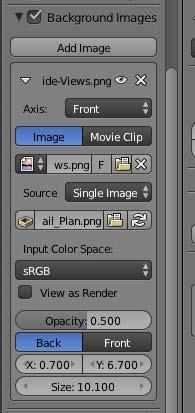
43 Add a NURS Surface Sphere (or a Mesh UV Sphere) to either end of the Rudder Handle object. Name the objects Rudder Sphere 1 and Rudder Sphere 2. Save your.blend file. Go to Front View. In the Background Display panel in the right notations properties panel click on the Open File Browser button.

44 Open the Sail_Plan.png image file. (You can download this image file from the course site.) This replaces the existing Background image with this new background image. Go to Wireframe display mode. Adjust the X and Y offset and the Image Size to align the background image with the sailboat. Here are my settings. Yours may be a bit different.
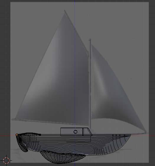
45

46 Model the center mast and the 3 sail spars using Mesh Cylinder objects. Name them Mast, Spar 1, Spar 2 and Spar 3. Put a sphere on top of the Mast object and name it Mast Sphere. Make sure to check the objects positions in side view to make sure they are all aligned in the center of the sailboat.

47 Go to Front view. Place your 3D cursor in the center of the left sail. Press SHIFT-A and add a NURBS Surface (Patch) to the scene.


48 Rotate the NURBS Surface Patch object 90 degrees around the X axis.

 each Control Point and position it to make the sail as shown")
49 Tab into edit mode. Select one of the Control Vertices and open the Active Spline panel in the Object data editor. Checkmark the U and V endpoint checkboxes. Select and Grab (GKEY) each Control Point and position it to make the sail as shown below. Tab out of Edit mode and go to Side View. Make sure the Sail is aligned in the center of the sailboat.

50 Tab back into Edit mode. Select the 4 inner control vertices and move them out a bit along the Z axis to give the sail a bit of a bow as shown below. Tab out of Edit mode. Name this object Sail 1. Go back to Front view. Place your 3D cursor in the center of the right sail. Add another NURBS Surface patch. Rotate it 90 degrees about the X axis. Tab into edit mode. In the Active Spline panel checkmark the U and V checkboxes. Adjust the Control vertices to make the sail. Note this is a triangle so you need to space out 2 sides of the Patch on one side of the sail as shown below.

51 Tab out of Edit mode and go to Side View. Make sure the Sail is aligned in the center of the sailboat. Tab back into Edit mode. Select the 4 inner control vertices and move them out a bit along the Z axis to give the sail a bit of a bow as you did on the other sail. Tab out of Edit mode. Name this object Sail 2. Go to Solid Shading mode.

52 Save your.blend file. Go to Front View. Uncheck the background Image checkbox. Select the Keel object. Hold down your SHIFT Key and add all of the other objects to the selection EXCEPT the Hull. Finally add the Hull object to the selection LAST. Press CTRL-P and make the Hull object a parent to all of the other Sailboat objects.

53 You should now be able to move the entire sailboat by selecting and moving the Hull object.


54 Using the Notation Properties panel on the right, set your 3D cursor to X,Y,Z = 0 Pres SHIFT-A and add a Cube object. Open the Modifier Editor and add an Ocean Modifier to the Cube object.

55 This creates an ocean-like object. Name this object Ocean. Select the Hull object and move the sailboat above the Ocean object. Select the Ocean object. In the ocean modifier panel set the controllers as shown below.


56 I will not explain the various controls here. You can find much information about the blender Ocean modifier online. Select the Hull object and move it down into the ocean. In the Timeline Editor, make sure you are on Frame #1. Select the Ocean object. In the ocean modifier panel, place your cursor over the Time controller button and press the IKEY. This turns the button yellow and inserts a Keyframe on frame #1 for the ocean effect.


57 In the Timeline Editor, go to Frame 250. In the ocean modifier panel, change the Time controller to 10. Place your cursor over the Time controller button and press the IKEY. This turns the button yellow and inserts a Keyframe on frame #250 for the ocean effect. Go back to Frame 1. In the Timeline Editor, press the play button and play the animation.


58 Note the animation of the ocean. Stop the animation and go back to Frame 1. Make sure the Ocean object is still selected. To make this a bit smoother, change your 3D Viewport Window to the Graph Editor Window. This displays the animation curve for the ocean. Click View / View All Press the TKEY and select Linear.

59 This will turn the animation curve into a straight line and the ocean will animate at a constant speed over the 350 frames. Go back to the 3D viewport Play the animation to see the difference. Stop the animation. Go back to Frame #1 and save your.blend file. We will make the sailboat float upon the Ocean object and react to the waves in a plausible manner. To do this we will use some of Blender s Physics controls. Go to Top View. In the Outliner panel, hide the Ocean object.


60 In Top view place your 3D cursor in the center of the sailboat. Press SHIFT-A and add a Plane object. Press the SKEY and scale up the plane object as shown below.

61 Tab into edit mode. With the 4 Plane vertices selected, subdivide the object. Select the center vertex on the left, hold down your SHIFT KEY and add the 3 center vertices to the selection then add the top right and bottom right vertices to the selection. Press the XKEY and delete these vertices. This leaves 3 vertices hanging out in space. Select these 3 vertices and press the FKEY to form a face.
62 Select the far right vertex and move it a bit out along the X axis as shown below.
63 Tab out of Edit mode. Go to front view and move the Plane object up along the Z axis as shown below.

64 Select the Hull object, hold down your SHIFT KEY and add the Plane object to the selection. Press CTRL-P ---- BUT DO NOT CONFIRM THE PARENTING INSTEAD Tab into Exit mode and select the 3 Plane vertices. Then press CTRL-P again and select Make Vertex Parent.
 are now the parent of the Hull object (and thus the parent of the whole sailboat.")
65 Tab out of edit mode. The Plane object (actually its vertices) are now the parent of the Hull object (and thus the parent of the whole sailboat. You can move the whole sailboat by selecting and moving the Plane object. In the Outliner panel, unhide the Ocean object.


66 Select the Plane object and move the sailboat down into the Ocean object. Press the SKEY and scale the Plane (and thus the sailboat) as shown below. Make sure you are in frame 1. Go to front view and raise the plane object slightly above the Ocean object.

67 With the Plane object selected click on the Physics Editor in the Right properties panel. Click on the Soft Body button, which will activate it. Uncheck, the Soft Body Goal checkbox.

68 Select the OCEAN OBJECT. In the Physics panel press the Collision button, which will activate it. NOTE: We have added a Soft Body Physics effect to the Plane and a Collision Physics effect to the Ocean object. This will cause the plane object (upon pressing the play animation button) to fall downward (along the Z axis) until it collides with the Ocean object. As the ocean object changes its mesh the Plane object will react to the collision and thus the sailboat will rock and bob with the waves. In the Timeline Editor, play the animation.

69 NOTE: You may have to stop the animation, go back to frame 1, select the Plane object, and adjust the height it is above the Ocean object. The closer it is to the Ocean object on frame 1 the less severe the initial collision will be. I set mine quite close to the surface of the Ocean object. Stop the animation. Go to Frame 1. In the notations properties Display panel on the right turn off the display of the Grid Floor and uncheck the X and Y Lines.


70 In the Outliner panel hide the Plane object. Play the animation. The Plane and grid lines are hidden from the display.

71 Stop the animation. Go back to frame #1 Save your.blend file. The next step is to animate the location of the sailboat. Go to Top view. In the Outliner Panel un-hide the Plane object. Select the Plane object and move it to the left of the Ocean object as shown below.


72 With the Plane object selected, go to the Physics editor and checkmark the Soft Body Goal checkbox and open up the panel. Set the Default to.350 and set the Stiffness to.430


73 Note: We could not have this Soft Body Goal box checked when the plane was in a stationary position but now need it to animate the Plane. With the Plane object selected and your cursor in the 3D viewport, AND ON FRAME #1, Press the IKEY and insert a Location keyframe on frame #1 for the Plane object. Go to Frame 250. Select the Plane object and move it to the right side of the Ocean as shown below.

74 Press the IKEY and insert a Location Keyframe for the Plane object on frame 250. Rotate your display a bit for a more dimensional view. Play the animation. Again, you may have to stop the animation and go back to frame 1, select the Plane object and adjust its height above the Ocean object. When you are satisfied, stop the animation and go to frame 1. To smooth out the animation, select the Plane object and go to the graph editor. Select the animation curve, press the TKEY and make it Linear (just like we did with the Ocean animation). When you are satisfied, stop the animation and go to frame 1. In the outliner Panel, hide the plane object and make it un-selectable and un-renderable. Save your.blend file. For this tutorial, we will apply simple colored material to the Sailboat and Ocean. Select each object (except the Plane), go to the Materials Editor, Click on the Diffuse color swatch and adjust the Red, Green and Blue color sliders as follows: Hull (Brown) R=.208, G-.076, B=0 Rail (Tan) R=.897, G=.358, B=.085 Rudder/Keel/Rudder Handle (Dark Brown) R=.240, G=.036, B=.036 Deck (Reddish Brown) R=.138, G=.051, B=0 Spheres (Gold) R=.335, G=.593, B=.047 Cabin (Bronze) R=.458, G=.161, B=0
. Go to Perspective View (NUMPAD-5). Rotate your view a bit to expose more of the ocean.")
75 Sails (Medium Yellow) R=1, G=1, B=.258 Mast/Spars (White) R=1, G=1, B=1 Ocean (Blue Green) R=0, G=.131, B=.246 Save your.blend file. Go to Front view. Add Layer #2 (We placed the Blender Camera object on layer #2 at the start of this tutorial). Go to Perspective View (NUMPAD-5). Rotate your view a bit to expose more of the ocean. Press View / Align View / Align Active Camera to View.

 to zoom in or out (using your mouse).")
76 This will align the camera to the perspective view. Note: you may have to select the Camera object (you can do this in camera view by selecting the camera rectangle) and move it or you may have to press SHIFT-F (which in camera view) to zoom in or out (using your mouse). Try to set your camera (WHILE IN FRAME 1) to look something like shown below:
.")
77 Next, you will probably need to select the Ocean object (while still in camera view) and scale it (SKEY) along the X axis. Make sure the sailboat animation from left to right and the ocean effect are all within the Camera view. Note: When you scale the Ocean object, the waves are a bit diminished (because of the scale). You may want to slightly increase the Choppiness setting on the Ocean modifier. I increased mine to 1.4 Save your.blend file. Go to Side View. Go to Frame #1. Add a Sun Lamp object on the left (near the camera) and a Hemi lamp on the left. Rotate the lamps as shown below. Go to Front View and rotate the lamps as shown below.


78 Select the Hemi Lamp object. Open the Object Data editor and set the Energy to.5 Open the World editor. Checkmark the Paper Sky and Blend Sky checkboxes.
. In the Mapping Panel, make sure both the Blend and Horizon boxes are checked.")
79 Go to the Texture Editor. Click the New button and change the Type to Image or Movie. Click on the Open button and select the RedSky.jpg image (This file can be downloaded from the course site). In the Mapping Panel, make sure both the Blend and Horizon boxes are checked. Here is a rendering of my scene taken at Frame # 90


80 To render a video of the animation, open the Render Editor in the right Properties panel. Set the Resolution to X=960, Y=720 In the Output panel, click on the Open browser button. Select your desktop as the location for the video file to be saved. Name the file Sailboat then click Accept. Select MPEG as the file output.


81 In the Encoding panel, select MPEG-4 as the Format. Save your.blend file. To render the animation, press the Animation button in the Rendering panel.
82 A completed copy of the.blend file named NURBS_Sailboat.blend is available on the course site.
First Animated Model Yellow Submarine
 Course: 3D Design Title: First Animated Model Yellow Submarine Blender: Version 2.6X Level: Beginning Author; Neal Hirsig (May 2012) First Animated Model Yellow Submarine Most of you are perhaps too young
Mesh Modeling Vase and Flower
 Course: 3D Design Title: Mesh Modeling Vase and Flower Dropbox File: VaseAndFlower.zip Blender: Version 2.45 Level: Beginning Author: Neal Hirsig (nhirsig@tufts.edu) Mesh Modeling Vase and Flower In this
Course: 3D Design Title: Mesh Modeling Hand Dropbox File: Hand.zip Blender: Version 2.41 Level: Beginning Author; Neal Hirsig
 Course: 3D Design Title: Mesh Modeling Hand Dropbox File: Hand.zip Blender: Version 2.41 Level: Beginning Author; Neal Hirsig (nhirsig@tufts.edu) Mesh Modeling Hand Open a new Blender file. We will be
Course: 3D Design Title: Mesh Modeling Shark Dropbox File: Shark.zip Blender: Version 2.45 Level: Beginning Author: Neal Hirsig
 Course: 3D Design Title: Mesh Modeling Shark Dropbox File: Shark.zip Blender: Version 2.45 Level: Beginning Author: Neal Hirsig (nhirsig@tufts.edu) Mesh Modeling Shark In this tutorial, we ll model a Shark.
Open Blender and click anywhere to remove the Splash Screen.
 Photo Detail Modelling the 3D Industrial Building Open Blender and click anywhere to remove the Splash Screen. Click on the File Menu and select "Save as". Save the Blender file as Industrial_Building01.blend
Mesh Modeling Dice Boolean
 Course: 3D Design Title: Mesh Modeling Dice - Boolean Dropbox File: Dice.zip Blender: Version 2.41 Level: Beginning Author: Neal Hirsig (nhirsig@tufts.edu) Mesh Modeling Dice Boolean In this tutorial,
Lathe Modeling Wine Glass
 Course: 3D Design Title: Bezier Curve Modeling Column Dropbox File: WineGlass.zip Blender: Version 2.41 Level: Beginning Author: Neal Hirsig (nhirsig@tufts.edu) Lathe Modeling Wine Glass In this tutorial,
Using Blender to Produce a Trainz Asset - Step 2-2 Add Materials and Texture (Continued)
") Apply Texture First, deselect everything in the 3D Editor Viewport by pressing the AKEY. When vertices, edges or faces are selected they appear orange. This key is also a toggle. Try pressing the AKEY
Apply Texture First, deselect everything in the 3D Editor Viewport by pressing the AKEY. When vertices, edges or faces are selected they appear orange. This key is also a toggle. Try pressing the AKEY
Object Manipulation and Basic Animation
 Object Manipulation and Basic Animation By Immer Baldos This document is a tutorial on basic modeling and animation using Blender version 2.49b. The goals are to create a Windmill using blender s built-in
This is the opening view of blender.
 This is the opening view of blender. Note that interacting with Blender is a little different from other programs that you may be used to. For example, left clicking won t select objects on the scene,
Split the 3D Editor Viewport
 Split the 3D Editor Viewport To create two viewports where there was previously one (the 3D Editor Viewport), click on the cross hatch in the upper right hand corner of the 3D Editor Viewport. When the
3D Modeling Course Outline
 3D Modeling Course Outline Points Possible Course Hours Course Overview 4 Lab 1: Start the Course Identify computer requirements. Learn how to move through the course. Switch between windows. Lab 2: Set
Basic Blender Commands This is just a partial list of Blender commands. Please visit the Blender.org website for more details.
 Basic Key Commands Basic Blender Commands This is just a partial list of Blender commands. Please visit the Blender.org website for more details. TAB key- Toggles between edit mode (vertex editing) and
Reference Image. Source:
 Mesh Modeling By Immer Baldos This document is a tutorial on mesh modeling using Blender version 2.49b. The goal is to create a model of an elevator. This tutorial will tackle creating the elevator cart,
Creating a Snowman Scene
 Creating a Snowman Scene By: Shane Trautsch Blender 2.72 What you will learn Basic Modeling Particle systems sculpting Materials and Textures Lighting Creating a Snow By now, you have created a snowman.
Chapter 12- NURBS & Meta Shape Basics
 Chapter 12- NURBS & Meta Shape Basics When you press Shift-A for Add, you will notice other object types beside meshes, cameras and lights that can be created. Two types of objects that can be created
Chapter 9- Animation Basics
 Timing, Moving, Rotating and Scaling Now that we know how to make stuff and make it look good, it s time to figure out how to move it around in your scene. Another name for an animation is Interpolation
Create a Rubber Duck. This tutorial shows you how to. Create simple surfaces. Rebuild a surface. Edit surface control points. Draw and project curves
 Page 1 of 24 Create a Rubber Duck This exercise focuses on the free form, squishy aspect. Unlike the flashlight model, the exact size and placement of the objects is not critical. The overall form is the
ARCHITECTURE & GAMES. A is for Architect Simple Mass Modeling FORM & SPACE. Industry Careers Framework. Applied. Getting Started.
 A is for Architect Simple Mass Modeling One of the first introductions to form and space usually comes at a very early age. As an infant, you might have played with building blocks to help hone your motor
Blender Notes. Introduction to Digital Modelling and Animation in Design Blender Tutorial - week 1 The Blender Interface and Basic Shapes
 Blender Notes Introduction to Digital Modelling and Animation in Design Blender Tutorial - week 1 The Blender Interface and Basic Shapes Introduction Blender is a powerful modeling, animation and rendering
Maya 2014 NURBS Modeling Tutorial Airship
 Maya 2014 NURBS Modeling Tutorial Airship Airships have captured human imagination for centuries and are featured prominently in books, film and video games. As an introduction to modeling with NURBS (non
Chapter 3- Creating & Editing Objects
 ` Chapter 3- Creating & Editing Objects Edit Mode- Mesh Editing Object Mode After you have created a mesh, you can go into Edit mode (Tab key or Mode option in window) and change its shape. In edit mode,
Computer graphics Labs: Blender (1/3) Modelling, transparency and reflection
 Modelling, transparency and reflection") Computer graphics Labs: Blender (1/3) Modelling, transparency and reflection University of Liège Department of Aerospace and Mechanical engineering Designed with Blender 2.76b Introduction to the interface
Computer graphics Labs: Blender (1/3) Modelling, transparency and reflection University of Liège Department of Aerospace and Mechanical engineering Designed with Blender 2.76b Introduction to the interface
1st Point. 2nd Point. hold shift & drag along Y. Splines
 Splines STEP 1: open 3DS Max _ from the Command Panel under the Create tab click on Shapes (note: shapes are really Splines) _ under Object Type click on Ellipse STEP 2: Expand the Keyboard Entry tab type
Extrude. Taper. STEP 04: Ctrl +V _ select Copy from the clone window _ name the copy: Slabs Mesh _ click OK
 Extrude STEP 01: open the class-08 3ds Max file _ select the ellipse _ command panel / modifier list _ select Extrude _ set the extrusion Amount: 400 _ STEP 02: with the perspective viewport current press
Chapter 3- Creating & Editing Objects
 Working with Basic Meshes Chapter 3- Creating & Editing Objects Now that we know how to move around in Blender, let s start doing some basic building and shaping. In this chapter we will talk about creating
User InterfaceChapter1:
 Chapter 1 User InterfaceChapter1: In this chapter you will learn about several aspects of the User Interface. You will learn about the overall layout of the UI, and then about the details of each element.
Basic Blender Commands This is just a partial list of Blender commands. Please visit the Blender.org website for more details.
 Basic Key Commands Basic Blender Commands This is just a partial list of Blender commands. Please visit the Blender.org website for more details. TAB key- Toggles between edit mode (vertex editing) and
lundi 7 janvier 2002 Blender: tutorial: Building a Castle Page: 1
 lundi 7 janvier 2002 Blender: tutorial: Building a Castle Page: 1 www.blender.nl this document is online at http://www.blender.nl/showitem.php?id=4 Building a Castle 2000 07 19 Bart Veldhuizen id4 Introduction
Working with the Dope Sheet Editor to speed up animation and reverse time.
 Bouncing a Ball Page 1 of 2 Tutorial Bouncing a Ball A bouncing ball is a common first project for new animators. This classic example is an excellent tool for explaining basic animation processes in 3ds
Animation Basics. Learning Objectives
 Animation Basics Learning Objectives After completing this chapter, you will be able to: Work with the time slider Understand animation playback controls Understand animation and time controls Morph compound
Module 4A: Creating the 3D Model of Right and Oblique Pyramids
 Inventor (5) Module 4A: 4A- 1 Module 4A: Creating the 3D Model of Right and Oblique Pyramids In Module 4A, we will learn how to create 3D solid models of right-axis and oblique-axis pyramid (regular or
Introduction to Maya
 1 M CO PY RI GH TE D MA TE RI AL Introduction to Maya aya is a powerful 3D modeling, animation, effects, and rendering solution that has been used in everything from product design to feature films. In
solidthinking Environment...1 Modeling Views...5 Console...13 Selecting Objects...15 Working Modes...19 World Browser...25 Construction Tree...
 Copyright 1993-2009 solidthinking, Inc. All rights reserved. solidthinking and renderthinking are trademarks of solidthinking, Inc. All other trademarks or service marks are the property of their respective
Sculpting 3D Models. Glossary
 A Array An array clones copies of an object in a pattern, such as in rows and columns, or in a circle. Each object in an array can be transformed individually. Array Flyout Array flyout is available in
Actions and Graphs in Blender - Week 8
 Actions and Graphs in Blender - Week 8 Sculpt Tool Sculpting tools in Blender are very easy to use and they will help you create interesting effects and model characters when working with animation and
4) Finish the spline here. To complete the spline, double click the last point or select the spline tool again.
 Finish the spline here. To complete the spline, double click the last point or select the spline tool again.") 1) Select the line tool 3) Move the cursor along the X direction (be careful to stay on the X axis alignment so that the line is perpendicular) and click for the second point of the line. Type 0.5 for
1) Select the line tool 3) Move the cursor along the X direction (be careful to stay on the X axis alignment so that the line is perpendicular) and click for the second point of the line. Type 0.5 for
Detailed Table of content. 3D View by tools - Header. 3D View by tools - Header detailed
 3D View by tools - Header Detailed Table of content...1 Introduction...16 Header...16 All Modes - View Menu...17 All Modes - Navigation Menu...24 All Modes, all Object types - Show / Hide...29 Object Mode
Using Blender to Create a Trainz Asset - Preparation
 Using Blender to Create a Trainz Asset - Preparation Project Folder It's a good idea to create a folder for each project to keep the various files associated with a project together. The folder can be
5 Subdivision Surfaces
 5 Subdivision Surfaces In Maya, subdivision surfaces possess characteristics of both polygon and NURBS surface types. This hybrid surface type offers some features not offered by the other surface types.
Project 9. Render a Kitchen
 Project 9 Render a Kitchen Creating a kitchen in 3D is one of those projects that help a lot in improving our skills. Since a kitchen can be created without having to resort to complex modeling skills,
Chapter 3- Creating & Editing Objects
 ` Chapter 3- Creating & Editing Objects Working with Basic Meshes Now that you can move around in Blender, let s start doing some basic building and shaping. In this chapter we will talk about creating
3ds Max Cottage Step 1. Always start out by setting up units: We re going with this setup as we will round everything off to one inch.
 3ds Max Cottage Step 1 Always start out by setting up units: We re going with this setup as we will round everything off to one inch. File/Import the CAD drawing Be sure Files of Type is set to all formats
Blender Lesson Ceramic Bowl
 Blender Lesson Ceramic Bowl This lesson is going to show you how to create a ceramic looking bowl using the free program Blender. You will learn how to change the view, add, delete, scale and edit objects
User Guide. for. JewelCAD Professional Version 2.0
 User Guide Page 1 of 121 User Guide for JewelCAD Professional Version 2.0-1 - User Guide Page 2 of 121 Table of Content 1. Introduction... 7 1.1. Purpose of this document... 7 2. Launch JewelCAD Professional
Notes on Blender: By Matthew Evett
 Notes on Blender: By Matthew Evett A synopsis of the Wiki: http://en.wikibooks.org/wiki/blender_3d:_noob_to_pro The Blender GUI is implemented via opengl. Thus the GUI is not Windowsstandard. Can resize
Chapter Adding 1- T Mo he tio B n le to nde Yo r ur Inte Scerfac ne e Landscape Scene Stormy Night.mp4 End 200 Default Animation frame 1 Location
 1- The Blender Interface Adding Motion to Your Scene Open your Landscape Scene file and go to your scene buttons. It s time to animate our dark and stormy night. We will start by making the correct setting
Spring 2011 Workshop ESSENTIALS OF 3D MODELING IN RHINOCEROS February 10 th 2011 S.R. Crown Hall Lower Core Computer Lab
 [1] Open Rhinoceros. PART 1 INTRODUCTION [4] Click and hold on the Boundary Lines in where they form a crossing and Drag from TOP RIGHT to BOTTOM LEFT to enable only the PERSPECTIVE VIEW. [2] When the
Modeling Technology Group
 Modeling Technology Group Hiroshi Hayashi David Ogirala Matt Nedrich Jeff Ridenbaugh Spencer Smith Saba Bokhari John Gray Charles Hellstrom Bryan Linthicum Polygon Models (part-1) What are polygons? -
Beginners Guide Maya. To be used next to Learning Maya 5 Foundation. 15 juni 2005 Clara Coepijn Raoul Franker
 Beginners Guide Maya To be used next to Learning Maya 5 Foundation 15 juni 2005 Clara Coepijn 0928283 Raoul Franker 1202596 Index Index 1 Introduction 2 The Interface 3 Main Shortcuts 4 Building a Character
MatterHackers. How to make a 3D model using Google Earth. Written By: Ryan Lutz. How to make a 3D model using Google Earth data
 MatterHackers How to make a 3D model using Google Earth data Written By: Ryan Lutz 2017 matterhackers.dozuki.com Page 1 of 20 INTRODUCTION EDIT 7/25/17: Sadly, Sketchup has changed the map service they
Where to get Blender. Go to Download the latest version
 Basic Building in Where to get Blender Go to www.blender.org Download the latest version Heads up! If using Linux the Software Center's safe version is out of date and doesn't do all that the new one does,
This lesson introduces Blender, covering the tools and concepts necessary to set up a minimal scene in virtual 3D space.
 3D Modeling with Blender: 01. Blender Basics Overview This lesson introduces Blender, covering the tools and concepts necessary to set up a minimal scene in virtual 3D space. Concepts Covered Blender s
Lesson 11. Polygonal Spaceship
 11 Polygonal Spaceship In this lesson, you will build and texture map a polygonal spaceship. Starting with a polygonal cube, you will extrude facets until you have a completed ship. You will then be able
Taking the Best Reference Photos
 Sides Three and Four To fill in the other two sides select the top vertice and the corners on a side where there is no face yet. Again, use FKEY to fill in a face. Repeat this for the last side to have
Editors - UV Image Editor by tools. Detailed table of content
 Editors - UV Image Editor by tools UV/Image Editor...13 Navigating in the UV IMage Editor viewport...13 Header - View Menu...13 Header - Image menu...16 Header - Select menu...18 Header - UV's menu...20
LAB # 2 3D Modeling, Properties Commands & Attributes
 COMSATS Institute of Information Technology Electrical Engineering Department (Islamabad Campus) LAB # 2 3D Modeling, Properties Commands & Attributes Designed by Syed Muzahir Abbas 1 1. Overview of the
Maya 2014 Introduction to Maya
 Maya 2014 Introduction to Maya Maya is an incredibly powerful animation software that can be used to create almost anything you can imagine. The purpose of this document is to help you become familiar
Character Modeling COPYRIGHTED MATERIAL
 38 Character Modeling p a r t _ 1 COPYRIGHTED MATERIAL 39 Character Modeling Character Modeling 40 1Subdivision & Polygon Modeling Many of Maya's features have seen great improvements in recent updates
Exercise Guide. Published: August MecSoft Corpotation
 VisualCAD Exercise Guide Published: August 2018 MecSoft Corpotation Copyright 1998-2018 VisualCAD 2018 Exercise Guide by Mecsoft Corporation User Notes: Contents 2 Table of Contents About this Guide 4
Module 2 Review. Assemblies and Rendering. Why Use Assemblies. Assemblies - Key Concepts. Sketch Planes Sketched Features.
 Module 2 Review Assemblies and Rendering EF 101 Modules 3.1, 3.2 Sketch Planes Sketched Features Extrude, Revolve Placed Features Hole, Fillet, Chamfer, Shell, Rect. Pattern Drawing Views Base, Ortho,
Simple Glass TNT Molecule Tutorial
 Simple Glass TNT Molecule Tutorial Quinten Kilborn Today, I ll be showing you how to make an awesome looking glass TNT molecule. I was messing with glass textures and found that it makes an awesome science
Modeling a Gear Standard Tools, Surface Tools Solid Tool View, Trackball, Show-Hide Snaps Window 1-1
 Modeling a Gear This tutorial describes how to create a toothed gear. It combines using wireframe, solid, and surface modeling together to create a part. The model was created in standard units. To begin,
A Guide to Autodesk Maya 2015
 A Guide to Autodesk Maya 2015 Written by Mitchell Youngerman Table of Contents Layout of Toolbars...pg 1 Creating Objects...pg 2 Selecting & Deselecting Objects...pg 3 Changing Perspective... pg 4 Transforming
Maya Lesson 3 Temple Base & Columns
 Maya Lesson 3 Temple Base & Columns Make a new Folder inside your Computer Animation Folder and name it: Temple Save using Save As, and select Incremental Save, with 5 Saves. Name: Lesson3Temple YourName.ma
Animating the Page IN THIS CHAPTER. Timelines and Frames
 e r ch02.fm Page 41 Friday, September 17, 1999 10:45 AM c h a p t 2 Animating the Page IN THIS CHAPTER Timelines and Frames Movement Tweening Shape Tweening Fading Recap Advanced Projects You have totally
By Roland Hess -- Based on the Blender Summer of Code tutorial by Michael Worcester
 Mesh Modeling Tutorial By Roland Hess -- Based on the Blender Summer of Code tutorial by Michael Worcester In the previous chapter, you learned how to manipulate objects in Blender. You've seen how to
Transforming Objects and Components
 4 Transforming Objects and Components Arrow selection Lasso selection Paint selection Move Rotate Scale Universal Manipulator Soft Modification Show Manipulator Last tool used Figure 4.1 Maya s manipulation
https://blenderzen.com/
 Blender Shortcut Keys Cheat Sheet Blender is a vast multi-purpose program designed to do some very complex things. Luckily for us the creators of Blender simplified the interface and squeezed most commands
Creating the Tilt Game with Blender 2.49b
 Creating the Tilt Game with Blender 2.49b Create a tilting platform. Start a new blend. Delete the default cube right click to select then press X and choose Erase Selected Object. Switch to Top view (NUM
Lesson 1: Creating T- Spline Forms. In Samples section of your Data Panel, browse to: Fusion 101 Training > 03 Sculpt > 03_Sculpting_Introduction.
 3.1: Sculpting Sculpting in Fusion 360 allows for the intuitive freeform creation of organic solid bodies and surfaces by leveraging the T- Splines technology. In the Sculpt Workspace, you can rapidly
3D Modeling and Design Glossary - Beginner
 3D Modeling and Design Glossary - Beginner Align: to place or arrange (things) in a straight line. To use the Align tool, select at least two objects by Shift left-clicking on them or by dragging a box
Autodesk Fusion 360 Training: The Future of Making Things Attendee Guide
 Autodesk Fusion 360 Training: The Future of Making Things Attendee Guide Abstract After completing this workshop, you will have a basic understanding of editing 3D models using Autodesk Fusion 360 TM to
MAYA; AN INTRODUCTION TO MAYA; EndOfLine.info;
 MAYA; AN INTRODUCTION TO MAYA; EndOfLine.info; Maya is an intuitive modelling and animation software that relies on a different set of techniques and strategies than Rhinoceros. It is important to note
Full Screen Layout. Main Menu Property-specific Options. Object Tools ( t ) Outliner. Object Properties ( n ) Properties Buttons
 Outliner. Object Properties ( n ) Properties Buttons") Object Tools ( t ) Full Screen Layout Main Menu Property-specific Options Object Properties ( n ) Properties Buttons Outliner 1 Animation Controls The Create and Add Menus 2 The Coordinate and Viewing
Object Tools ( t ) Full Screen Layout Main Menu Property-specific Options Object Properties ( n ) Properties Buttons Outliner 1 Animation Controls The Create and Add Menus 2 The Coordinate and Viewing
Going 3D with Blender: A room with toys
 LinuxFocus article number 318 http://linuxfocus.org Going 3D with Blender: A room with toys by Katja Socher About the author: Katja is the German editor of LinuxFocus. She likes
Solidworks 2006 Surface-modeling
 Solidworks 2006 Surface-modeling (Tutorial 2-Mouse) Surface-modeling Solid-modeling A- 1 Assembly Design Design with a Master Model Surface-modeling Tutorial 2A Import 2D outline drawing into Solidworks2006
Chapter 13 - Modifiers
 Chapter 13 - Modifiers The modifier list continues to grow with each new release of Blender. We have already discussed the Subdivision Surface (SubSurf) and Ocean modifiers in previous chapters and will
Modeling Level Design
 Summary This tutorial has introduced you to several of the tools you can use to make a low-polygon model with editable poly functionality. These tools can be adapted to the task of modeling any low-polygon
FLUID DESIGNER FOR 3D PRINTING Installing & Configuring Startup Screen
 FLUID DESIGNER FOR 3D PRINTING Installing & Configuring Startup Screen INSTALLING THE APPLICATION After downloading the file FluidDesigner3DPrinting.Zip from our web site you should install it in either
Introduction to Digital Modelling and Animation in Design week 4 Textures
 Introduction to Digital Modelling and Animation in Design week 4 Textures Thaleia Deniozou - - - - - - - - - - - - - - - - - - - - - - - - - - - - - - - - - - - - - - - - - - - - - - - - - - - - - - -
Blender. Basics. Second Edition. Classroom Tutorial Book. By James Chronister
 Blender Basics Second Edition Classroom Tutorial Book By James Chronister 2004, 2006 second edition by James Chronister. This document may be reproduced without permission from the author, but please let
An Introduction to Autodesk Revit Massing, Surface Divisions, and Adaptive Components
 An Introduction to Autodesk Revit Massing, Surface Divisions, and Adaptive Components Chad Smith KarelCAD, Australia AB2463-L As the Revit massing tools become more polished and robust, users are becoming
move object resize object create a sphere create light source camera left view camera view animation tracks
 Computer Graphics & Animation: CS Day @ SIUC This session explores computer graphics and animation using software that will let you create, display and animate 3D Objects. Basically we will create a 3
Images from 3D Creative Magazine. 3D Modelling Systems
 Images from 3D Creative Magazine 3D Modelling Systems Contents Reference & Accuracy 3D Primitives Transforms Move (Translate) Rotate Scale Mirror Align 3D Booleans Deforms Bend Taper Skew Twist Squash
Avid FX Tutorials. Understanding the Tutorial Exercises
 Avid FX Tutorials Understanding the Tutorial Exercises The following tutorial exercises provide step-by-step instructions for creating various kinds of effects, while exploring many aspects of the Avid
CS148: Maya Lecture. October 9th, 2017 David Hyde
 CS148: Maya Lecture October 9th, 2017 David Hyde Outline Rendering: A Bird s Eye View 3D Art Tools Maya Outline Demo Rendering: A Bird s Eye View AND WHERE DOES CS148 FIT IN? Image: CS148 2015 Scanline
WIRE BASICS ESTIMATED TIME REQUIRED. This tutorial will teach you the basics of sketching wires and using them as contours for solid objects.
 WIRE BASICS This tutorial will teach you the basics of sketching wires and using them as contours for solid objects. ESTIMATED TIME REQUIRED 30 Minutes LEARNING GOALS In this tutorial you will learn how
Chapter 16: Boat Hull - Loft and Sweep
 This tutorial demonstrates classic boat hull lofting techniques using typical plan and profile curves. The classic hull shape is based on a design from an old Boat Builder s Handbook magazine. Many designs
Getting Started with ShowcaseChapter1:
 Chapter 1 Getting Started with ShowcaseChapter1: In this chapter, you learn the purpose of Autodesk Showcase, about its interface, and how to import geometry and adjust imported geometry. Objectives After
AutoCAD 2009 Tutorial
 AutoCAD 2009 Tutorial Second Level: 3D Modeling Randy H. Shih Oregon Institute of Technology SDC PUBLICATIONS Schroff Development Corporation www.schroff.com Better Textbooks. Lower Prices. AutoCAD 2009
User Interface Software Projects
 User Interface Software Projects Assoc. Professor Donald J. Patterson INF 134 Winter 2013 The author of this work license copyright to it according to the Creative Commons Attribution-Noncommercial-Share
REU Modeling Course Day 1. AutoDesk Maya - Program Introduction + Getting Started
 REU Modeling Course Day 1 AutoDesk Maya - Program Introduction + Getting Started Workshop Workflow Compare/introduce CAD programs and purposes review Creating/Experimenting with Today s mini goal CAD Programs
Tutorial: Making your First Level
 Tutorial: Making your First Level This tutorial walks you through the steps to making your first level, including placing objects, modifying the terrain, painting the terrain and placing vegetation. At
How to start your Texture Box Project!
 How to start your Texture Box Project! Shapes, naming surfaces, and textures. Lightwave 11.5 Part One: Create Your Shape Choose Start, Programs, New Tek, Lightwave and Modelor (the orange one). 1.In one
Textures and UV Mapping in Blender
 Textures and UV Mapping in Blender Categories : Uncategorised Date : 21st November 2017 1 / 25 (See below for an introduction to UV maps and unwrapping) Jim s Notes regarding Blender objects, the UV Editor
Chapter 19- Object Physics
 Chapter 19- Object Physics Flowing water, fabric, things falling, and even a bouncing ball can be difficult to animate realistically using techniques we have already discussed. This is where Blender's
Lesson 1 Parametric Modeling Fundamentals
 1-1 Lesson 1 Parametric Modeling Fundamentals Create Simple Parametric Models. Understand the Basic Parametric Modeling Process. Create and Profile Rough Sketches. Understand the "Shape before size" approach.
2nd Set of Gollum s Hotkeys
 2nd Set of Gollum s Hotkeys Hotkeys and Maps In Maya Display Settings 4 Shading > Wireframe 5 Shaded display 6 Shaded and Textured display 7 Lighting > Use All Lights 1 Rough Quality Display Setting 2
Chapter 1- The Blender Interface
 The Blender Screen When I first looked at Blender and read some tutorials I thought that this looked easy and made sense. After taking the program for a test run, I decided to forget about it for a while