THE NEW UPGRADED INTERFACE OF SCADA PRO... 3 II. DETAILED DESCRIPTION OF THE NEW INTERFACE...
|
|
|
- Erik Hoover
- 5 years ago
- Views:
Transcription


1
2 CONTENTS I. THE NEW UPGRADED INTERFACE OF SCADA PRO... 3 II. DETAILED DESCRIPTION OF THE NEW INTERFACE... 4 VIEW ZOOM PAN DYNAMIC ROTATION DISPLAY REDRAW D-3D RENDERING MATHEMATICAL SWITCHES VIEWS DYNAMIC SECTION

3 I. THE NEW UPGRADED INTERFACE of SCADA Pro 3
4 II. DETAILED DESCRIPTION OF THE NEW INTERFACE In the new upgraded SCADA Pro, all program commands are grouped in 12 Units. View The 3 rd Unit entitled View includes the following four groups of commands: 1. Zoom 2. Display 3. Views 4. Dynamic Section 1.1 Zoom The command group Zoom contains commands to make changes on the displayed size of a drawing on the computer screen. The Zoom commands are: Zoom Window Zoom Extends Zoom Previous Zoom In (Step +) Zoom Out (Step -) 1.2 Pan The tool Pan reflects the mouse movements on the screen so we can move around the screen effortlessly. 1.3 Dynamic Rotation The tool Dynamic Rotation allows the rotation around the screen of the entire three-dimensional structure. 4

 or use the command \"Mathematical\" (See below). 2.3 Rendering The command Rendering is used to create a virtual representation of the structure.")
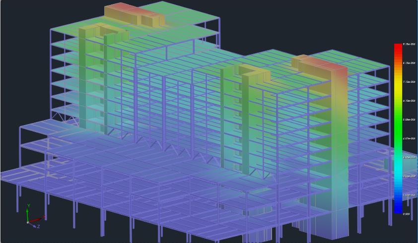
5 2. Display The command group Display contains significant presentation commands. 2.1 Redraw The tool Redraw simply repaints the screen, without drawing residuals D-3D The command 2D-3D is used to toggle between 2D and 3D representation. The requirement for the 3D representation is the calculation of the mathematical model of the project. (Unit Tools>>Calculation) In the 3D view, the user can choose the type of model display between the mathematical, the physical, or both of them Select the type by clicking on the horizontal "status bar" (See INTRODUCTION) or use the command "Mathematical" (See below). 2.3 Rendering The command Rendering is used to create a virtual representation of the structure. A precondition for rendering is the calculation of the mathematical model of the project. (Unit Tools>>Calculation) In the photorealistic display, the elements are colored according to the colors of the corresponding layer. 5
. 2.")

 and the 3D view.")
6 With one click on the colored button of the horizontal status line, the elements are colored according to their material (concrete-gray, metallic-blue, timber-brown, masonry-beige). 2.4 Mathematical This command is used to toggle between mathematical, physical, and both models 3D representation. The sequential selection of these three options alternates the display type of the model. A precondition for these representations is the calculation of the mathematical model of the project. (Unit Tools>>Calculation) and the 3D view. A different way to do the same thing is by clicking directly on the horizontal status line. 2.5 Switches 6
7 Depending on the case the tool Switches can be enabled or disabled. Specifically: Toolbar enabled the toolbar on the interface is displayed Auto Trim enabled a beam that crosses over a column is trimmed Deactivate when you want to insert a Shape Footing under basement walls Solid Cross Section enabled color view of the solid cross-sections Attribute Points enabled the columns input points and the beam s input axes are displayed Beam Axes enabled the three local axes of the beam, the centroid, and the two laterals are displayed Global Axes enabled the global axes are displayed Local Axes enabled the local axes of the members are displayed The local axes Green: y axis, Blue: z axis and Red: x axis are represented by the corresponding color: Members Releases enabled member releases are displayed Import File Display enabled the import DWG or DXF file is displayed Slab Model Display enabled the slab s mathematical model is displayed Zoellner Domes Display enabled Zoellner domes are displayed 3. Views Each 2D View displays the corresponding side of the structure. Precondition: the calculation of the Tools>>Calculation) mathematical model of the project. (Unit 4. Dynamic Section In photorealistic visualization, the activation ON of the command group Dynamic Section displays an intersection plane on the screen. 7


8 Move and turn the level by using the arrow or select the predifined intersection planes XY, XZ, YZ. 8
User s Manual ❹ Tools
 User s Manual ❹ Tools 2 CONTENTS I. THE NEW UPGRADED INTERFACE of SCADA Pro 5 II. DETAILED DESCRIPTION OF THE NEW INTERFACE 6 1. Tools 6 1.1 Structural Elements 6 1.2 USC-WCS 12 1.3 Model 13 1.4 Members
3D Surface Plots with Groups
 Chapter 942 3D Surface Plots with Groups Introduction In PASS, it is easy to study power and sample size calculations for a range of possible parameter values. When at least 3 input parameters vary, you
Rectangular Coordinates in Space
 Rectangular Coordinates in Space Philippe B. Laval KSU Today Philippe B. Laval (KSU) Rectangular Coordinates in Space Today 1 / 11 Introduction We quickly review one and two-dimensional spaces and then
User s Manual ⓿Introduction
 User s Manual ⓿Introduction Note This manual, along with all the training materials for Scada Pro, are a complementary guide for the proper use of the application and by no means are meant to replace competent
User s Manual ⓿Introduction
 User s Manual ⓿Introduction Note This manual, along with all the training material of Scada Pro, aim solely to act as a guide for the proper use of the application. Solid engineering knowledge in conjunction
PASS Sample Size Software
 Chapter 941 Introduction In PASS, it is easy to study power and sample size calculations for a range of possible parameter values. When at least 2 input parameters vary, you can create stunning 3D power
Contents CHAPTER 2 MODELING
 Contents I. THE NEW UPGRADED INTERFACE of SCADA Pro 3 II. DETAILED DESCRIPTION OF THE NEW INTERFACE 4 1. Modeling 4 1.1 Columns 4 1.2 Beams 8 1.3 Foundation 11 1.4 Surface Elements 14 1.5 Elements 36 1.6
INTRODUCTION TO SCADA Pro. Note
 Note This manual, along with all the training material of SCADA Pro, aims solely to act as a guide for the proper use of the application. Solid engineering knowledge in conjunction with the technical legislation
User s Manual ❷ Modeling
 User s Manual ❷ Modeling 2 Contents I. THE NEW UPGRADED INTERFACE of SCADA Pro 5 II. DETAILED DESCRIPTION OF THE NEW INTERFACE 6 1. Modeling 6 1.1 Columns 6 1.2 Beams 10 1.3 Foundation 13 1.4 Surface Elements
Flair Geometry Editor Part I. Beginners FLUKA Course
 Flair Geometry Editor Part I Beginners FLUKA Course Starting the Geometry Editor Click on icon or from Menu View Geometry Editor or with [F4] shortcut Either start flair with option -g 2 Geometry editor
SPACE - A Manifold Exploration Program
 1. Overview SPACE - A Manifold Exploration Program 1. Overview This appendix describes the manifold exploration program SPACE that is a companion to this book. Just like the GM program, the SPACE program
Basic Modeling 1 Tekla Structures 12.0 Basic Training September 19, 2006
 Tekla Structures 12.0 Basic Training September 19, 2006 Copyright 2006 Tekla Corporation Contents Contents 3 1 5 1.1 Start Tekla Structures 6 1.2 Create a New Model BasicModel1 7 1.3 Create Grids 10 1.4
Column - solid section
 1 Column - solid section This example demonstrates how how to design a column with an arbitrary cross-section defined by the user. The model is a simple one member column, loaded with an axial load and
Roof Designer USER S GUIDE
 Roof Designer USER S GUIDE Roof Designer-1 Roof Designer-2 Roof Designer The Roof Designer makes it easy to define and place custom roofs in your project. You can start the Roof Designer independently,
General Information Project management Introduction... 4 Getting Started Input geometry... 7
 Tutorial Shell Tutorial Shell All information in this document is subject to modification without prior notice. No part or this manual may be reproduced, stored in a database or retrieval system or published,
ADAPT-Builder. Toolbar Descriptions Updated November Copyright All rights reserved 2017
 ADAPT-Builder Toolbar Descriptions Updated November 2017 Copyright All rights reserved 2017 Main Toolbar The Main Toolbar is where the typical functions that are in most programs such as New, Open, Save,
STRUCTURAL CONCRETE SOFTWARE SYSTEM ADAPT-MODELER 2010 USER MANUAL. Copyright 2010
 MNL 403 STRUCTURAL CONCRETE SOFTWARE SYSTEM ADAPT-MODELER 2010 USER MANUAL Copyright 2010 support@adaptsoft.com www.adaptsoft.com ADAPT Corporation, Redwood City, California, USA, Tel: +1 (650) 306-2400
User s Manual. ❶Basic
 User s Manual ❶Basic Note This manual, along with all the training material of Scada Pro, aim solely to act as a guide for the proper use of the application. Solid engineering knowledge in conjunction
QuickTutor. An Introductory SilverScreen Modeling Tutorial. Solid Modeler
 QuickTutor An Introductory SilverScreen Modeling Tutorial Solid Modeler TM Copyright Copyright 2005 by Schroff Development Corporation, Shawnee-Mission, Kansas, United States of America. All rights reserved.
Chapter 6. Concept Modeling. ANSYS, Inc. Proprietary Inventory # May 11, ANSYS, Inc. All rights reserved.
 Chapter 6 Concept Modeling 6-1 Contents Concept Modeling Creating Line Bodies Modifying i Line Bodies Cross Sections Cross Section Alignment Cross Section Offset Surfaces From Lines Surfaces From Sketches
Module 1: Basics of Solids Modeling with SolidWorks
 Module 1: Basics of Solids Modeling with SolidWorks Introduction SolidWorks is the state of the art in computer-aided design (CAD). SolidWorks represents an object in a virtual environment just as it exists
solidthinking Environment...1 Modeling Views...5 Console...13 Selecting Objects...15 Working Modes...19 World Browser...25 Construction Tree...
 Copyright 1993-2009 solidthinking, Inc. All rights reserved. solidthinking and renderthinking are trademarks of solidthinking, Inc. All other trademarks or service marks are the property of their respective
MATRIX REVIEW PROBLEMS: Our matrix test will be on Friday May 23rd. Here are some problems to help you review.
 MATRIX REVIEW PROBLEMS: Our matrix test will be on Friday May 23rd. Here are some problems to help you review. 1. The intersection of two non-parallel planes is a line. Find the equation of the line. Give
Exercise Guide. Published: August MecSoft Corpotation
 VisualCAD Exercise Guide Published: August 2018 MecSoft Corpotation Copyright 1998-2018 VisualCAD 2018 Exercise Guide by Mecsoft Corporation User Notes: Contents 2 Table of Contents About this Guide 4
NX Tutorial - Centroids and Area Moments of Inertia ENAE 324 Aerospace Structures Spring 2015
 NX will automatically calculate area and mass information about any beam cross section you can think of. This tutorial will show you how to display a section s centroid, principal axes, 2 nd moments of
Lesson 1 Parametric Modeling Fundamentals
 1-1 Lesson 1 Parametric Modeling Fundamentals Create Simple Parametric Models. Understand the Basic Parametric Modeling Process. Create and Profile Rough Sketches. Understand the "Shape before size" approach.
HOW TO SETUP AND RUN SHIVA...
 TABLE OF CONTENTS HOW TO SETUP AND RUN SHIVA... 1 REQUIREMENTS... 1 Java... 1 Architecture... 2 LAUNCHING SHIVA... 2 LOADING THE ATLAS... 2 USAGE INSTRUCTIONS... 2 FILES... 2 Image Volumes... 2 Label Indices...
Publication Number spse01695
 XpresRoute (tubing) Publication Number spse01695 XpresRoute (tubing) Publication Number spse01695 Proprietary and restricted rights notice This software and related documentation are proprietary to Siemens
Module 8A: Creating a Sheet Metal Part & Flat Pattern Wrapping the 3D Space of a Polyhedron
 1 Module 8A: Creating a Sheet Metal Part & Flat Pattern Wrapping the 3D Space of a Polyhedron In this Module, we will learn how to create a sheet metal part wrapping a polyhedron based on an octagonal
Formation SCIA ESA PT
 Formation SCIA ESA PT General Environment: Options, Setup, Help New Project: Project data Windows/toolbars : - Workspace, Window with Main tree and window for properties - Windows change place / close
Views of a 3-D Clevis
 LESSON 5 Views of a 3-D Clevis Objectives: To become familiar with different view options. To create and modify z-axis and arbitrary clipping planes. PATRAN301ExerciseWorkbook-Release7.5 5-1 5-2 PATRAN
Tutorial 4: Texture Mapping Techniques
 Tutorial 4: Texture Mapping Techniques Completion time 40 minutes In the previous tutorial we learned how to create materials, and how to assign texture maps to those materials. In this tutorial we will
LAB # 2 3D Modeling, Properties Commands & Attributes
 COMSATS Institute of Information Technology Electrical Engineering Department (Islamabad Campus) LAB # 2 3D Modeling, Properties Commands & Attributes Designed by Syed Muzahir Abbas 1 1. Overview of the
Engineering Geology. Engineering Geology is backbone of civil engineering. Topographic Maps. Eng. Iqbal Marie
 Engineering Geology Engineering Geology is backbone of civil engineering Topographic Maps Eng. Iqbal Marie Maps: are a two dimensional representation, of an area or region. There are many types of maps,
Structural & Thermal Analysis Using the ANSYS Workbench Release 12.1 Environment
 ANSYS Workbench Tutorial Structural & Thermal Analysis Using the ANSYS Workbench Release 12.1 Environment Kent L. Lawrence Mechanical and Aerospace Engineering University of Texas at Arlington SDC PUBLICATIONS
Advance Design. Tutorial
 TUTORIAL 2018 Advance Design Tutorial Table of Contents About this tutorial... 1 How to use this guide... 3 Lesson 1: Preparing and organizing your model... 4 Step 1: Start Advance Design... 5 Step 2:
Publication Number spse01695
 XpresRoute (tubing) Publication Number spse01695 XpresRoute (tubing) Publication Number spse01695 Proprietary and restricted rights notice This software and related documentation are proprietary to Siemens
UNIT 11: Revolved and Extruded Shapes
 UNIT 11: Revolved and Extruded Shapes In addition to basic geometric shapes and importing of three-dimensional STL files, SOLIDCast allows you to create three-dimensional shapes that are formed by revolving
3D Design with 123D Design
 3D Design with 123D Design Introduction: 3D Design involves thinking and creating in 3 dimensions. x, y and z axis Working with 123D Design 123D Design is a 3D design software package from Autodesk. A
Version October 2015 RFEM 5. Spatial Models Calculated acc. to Finite Element Method. Introductory Example
 Version October 2015 Program RFEM 5 Spatial Models Calculated acc. to Finite Element Method Introductory Example All rights, including those of translations, are reserved. No portion of this book may be
Custom Components for Precast Concrete Tekla Structures 12.0 Basic Training September 19, 2006
 Custom Components for Precast Concrete Tekla Structures 12.0 Basic Training September 19, 2006 Copyright 2006 Tekla Corporation Contents Contents...i 4...3 4.1 Define Custom Part of Fastener Plate...3
Chair. Top Rail. on the Standard Views toolbar. (Ctrl-7) on the Weldments toolbar. at bottom left corner of display to deter- mine sketch plane.
 on the Weldments toolbar. at bottom left corner of display to deter- mine sketch plane.") Chapter 7 A. 3D Sketch. Step 1. If necessary, open your CHAIR file. Chair Top Rail Step 2. Click Isometric on the Standard Views toolbar. (Ctrl-7) Step 3. Zoom in around top of back leg, Fig. 1. To zoom,
Chapter 7 A. 3D Sketch. Step 1. If necessary, open your CHAIR file. Chair Top Rail Step 2. Click Isometric on the Standard Views toolbar. (Ctrl-7) Step 3. Zoom in around top of back leg, Fig. 1. To zoom,
Autodesk Inventor Design Exercise 2: F1 Team Challenge Car Developed by Tim Varner Synergis Technologies
 Autodesk Inventor Design Exercise 2: F1 Team Challenge Car Developed by Tim Varner Synergis Technologies Tim Varner - 2004 The Inventor User Interface Command Panel Lists the commands that are currently
Overview The egg cup is made by
 123D Design Tutorial: Egg cup using the Loft Tool Before using these instructions, it is very helpful to watch this video screencast of the CAD drawing actually being done in the software. Click this link
DWG/DXF Export. Some attribute values in blocks weren't exporting correctly.
 DesignCAD 3D Max 20.1 Release Notes Nov. 9, 2010 DesignCAD 3D Max 20.1 introduces the following fixes and changes: DWG/DXF Export. Sometimes arcs and elliptical arcs, when exported to dwg or dxf format,
Home Designer Update Notes
 Home Designer 17.3.2.2 Update Notes October 14, 2015 1 General Notes This is a list of the changes made to Home Designer 2016 in the 17.3.2.2, 17.3.1.1, 17.3.0.25, 17.2.0.69, 17.1.2.2, 17.1.1.3, and 17.1.0.51
Visual 2012 Help Index
 Visual 2012 Help Index Absolute Coordinates 2.1 Cartesian Coordinates Aim 7.4.3 Place and Aim Luminaires 7.4.4 Reaiming Luminaires Align Cursor and Plane to Current View 9.6 Align to View Align Cursor
4. Generating a Relief
 ArtCAM Pro 5.5 Relief. The 3D model created by ArtCAM Pro is called a Relief and is shown in the 3D View. The Relief is defined by a resolution in a similar way to a bitmap image. But, instead of each
Autodesk Inventor - Basics Tutorial Exercise 1
 Autodesk Inventor - Basics Tutorial Exercise 1 Launch Inventor Professional 2015 1. Start a New part. Depending on how Inventor was installed, using this icon may get you an Inch or Metric file. To be
FOUNDATION IN OVERCONSOLIDATED CLAY
 1 FOUNDATION IN OVERCONSOLIDATED CLAY In this chapter a first application of PLAXIS 3D is considered, namely the settlement of a foundation in clay. This is the first step in becoming familiar with the
Introduction to ANSYS DesignModeler
 Lecture 9 Beams and Shells 14. 5 Release Introduction to ANSYS DesignModeler 2012 ANSYS, Inc. November 20, 2012 1 Release 14.5 Beams & Shells The features in the Concept menu are used to create and modify
Getting Started. What is SAS/SPECTRAVIEW Software? CHAPTER 1
 3 CHAPTER 1 Getting Started What is SAS/SPECTRAVIEW Software? 3 Using SAS/SPECTRAVIEW Software 5 Data Set Requirements 5 How the Software Displays Data 6 Spatial Data 6 Non-Spatial Data 7 Summary of Software
Getting Started With XPresReview
 Getting Started With XPresReview Step One : Downloading & Installing The XPresReview Software Cagenix utilizes a software package called XpresReview for our design approval process. DOWNLOAD LINK : http://xpresreview.cagenix.com
Quick Start Guide. Delivered by. Support: Training:
 Quick Start Guide For support and training on the full range of CSC products, please contact Support: support@cscworld.com Training: training@cscworld.com Delivered by Contents 1.0 Introducing Solve...
Designing a Chair. Lesson 6
 Lesson 6 Designing a Chair This lesson illustrates how to design a chair using the Curves Network modeling tool. The following modeling tools will be covered: Curves Network. Skin. Intersect. Trim. Mirror.
User Interface Guide
 User Interface Guide 1 Contents Overview... 3 Tabmenu... 4 Design modes... 4 Tool groups... 5 Design function groups... 5 Main menu... 6 Toolbars... 7 Drawing area... 9 Status bar... 11 Coordinate box...
Parametric Modeling. With. Autodesk Inventor. Randy H. Shih. Oregon Institute of Technology SDC PUBLICATIONS
 Parametric Modeling With Autodesk Inventor R10 Randy H. Shih Oregon Institute of Technology SDC PUBLICATIONS Schroff Development Corporation www.schroff.com www.schroff-europe.com 2-1 Chapter 2 Parametric
Introduction to Autodesk Revit Structure
 11/30/2005-5:00 pm - 6:30 pm Room:N. Hemispheres (Salon E2) (Dolphin) Walt Disney World Swan and Dolphin Resort Orlando, Florida Nicolas Mangon - Autodesk SD35-1 This year, Autodesk is introducing the
Chapter 2 Parametric Modeling Fundamentals
 2-1 Chapter 2 Parametric Modeling Fundamentals Create Simple Extruded Solid Models Understand the Basic Parametric Modeling Procedure Create 2-D Sketches Understand the Shape before Size Approach Use the
Table of contents. I Preface. II First steps 1. 3D stage 2. Your first stage
 Table of contents I Preface 1 II First steps 3 1. 3D stage 2. Your first stage III User mode 2 3 7 1. Rendering options 2. Resolution 3. Cameras 4. DMX levels 5. Universes patch 6. Movie recorder 6 7 7
Using IPACS Webserver:
 Using IPACS Webserver: Logging On: The IPACS Webserver can be accessed from any PC with internet connectivity. 1. Open Internet Explorer or your internet service provider. 2. Type the IPACS web address
Important Note - Please Read:
 Important Note - Please Read: This tutorial requires version 6.01 or later of SAFE to run successfully. You can determine what version of SAFE you have by starting the program and then clicking the Help
Appendix B: Creating and Analyzing a Simple Model in Abaqus/CAE
 Getting Started with Abaqus: Interactive Edition Appendix B: Creating and Analyzing a Simple Model in Abaqus/CAE The following section is a basic tutorial for the experienced Abaqus user. It leads you
Module 1B: Parallel-Line Flat Pattern Development of Sheet- Metal Folded Model Wrapping the 3D Space of A Truncated Right Prism
 Inventor (5) Module 1B: 1B- 1 Module 1B: Parallel-Line Flat Pattern Development of Sheet- Metal Folded Model Wrapping the 3D Space of A Truncated Right Prism In this Module, we will learn how to create
Class IX Mathematics (Ex. 3.1) Questions
 Questions") Class IX Mathematics (Ex. 3.1) Questions 1. How will you describe the position of a table lamp on your study table to another person? 2. (Street Plan): A city has two main roads which cross each other
Class IX Mathematics (Ex. 3.1) Questions 1. How will you describe the position of a table lamp on your study table to another person? 2. (Street Plan): A city has two main roads which cross each other
Tutorial 14b: Advanced polygonal modeling
 Tutorial 14b: Advanced polygonal modeling Table of Contents................................... 3 2 Download items Tutorial data Tutorial PDF Part 1: Polygonal Modeling Note that you can also find a video
Structural & Thermal Analysis using the ANSYS Workbench Release 11.0 Environment. Kent L. Lawrence
 ANSYS Workbench Tutorial Structural & Thermal Analysis using the ANSYS Workbench Release 11.0 Environment Kent L. Lawrence Mechanical and Aerospace Engineering University of Texas at Arlington SDC PUBLICATIONS
Copyright (C) 2001 Roland DG Corporation
 2001 Roland DG Corporation") User's Manual Unauthorized copying or transferal, in whole or in part, of this manual is prohibited. The contents of this operation manual and the specifications of this product are subject to change without
User's Manual Unauthorized copying or transferal, in whole or in part, of this manual is prohibited. The contents of this operation manual and the specifications of this product are subject to change without
12.6 Cylinders and Quadric Surfaces
 12 Vectors and the Geometry of Space 12.6 and Copyright Cengage Learning. All rights reserved. Copyright Cengage Learning. All rights reserved. and We have already looked at two special types of surfaces:
Arch 226 CAD in Practice Fall 2011 Class-06 Rhino. [Starting Rhino] Viewports Command Line Prompts, Options Status Bar Toolbars
![Arch 226 CAD in Practice Fall 2011 Class-06 Rhino. [Starting Rhino] Viewports Command Line Prompts, Options Status Bar Toolbars](/thumbs/92/110467085.jpg "Arch 226 CAD in Practice Fall 2011 Class-06 Rhino. [Starting Rhino] Viewports Command Line Prompts, Options Status Bar Toolbars") [Starting ] Viewports Command Line Prompts, Options Status Bar Toolbars [Understanding Views] Zoom, Pan, and Rotate the View Mouse Wheel Zoom Right Mouse Button Pan, Rotate, and Zoom Pan- shift/right click,
[Starting ] Viewports Command Line Prompts, Options Status Bar Toolbars [Understanding Views] Zoom, Pan, and Rotate the View Mouse Wheel Zoom Right Mouse Button Pan, Rotate, and Zoom Pan- shift/right click,
Multiframe Windows Version 16. User Manual
 Multiframe Windows Version 16 User Manual Bentley Systems, Incorporated 2013 License & Copyright Multiframe Program & User Manual 2013 Bentley Systems, Incorporated iii Table of Contents License & Copyright...
introduction Manipulate objects and navigate in the 3Dworld Use the electronic catalogue (ecat) Change component parameters Connect components
 Change component parameters Connect components") Tutorials HVCG Conveyors HVCG Conveyor Tutorial /11 Related files HVCGConveyorTutorial.vcp Description The HVCGConveyorTutorial component package extracts the equipment models used in this tutorial. You
Tutorials HVCG Conveyors HVCG Conveyor Tutorial /11 Related files HVCGConveyorTutorial.vcp Description The HVCGConveyorTutorial component package extracts the equipment models used in this tutorial. You
Glider. Clay. Fig. 1 Side face. Step 5. In the Convert Entities Property Manager: click side face, Fig. 3 click OK twice, Fig. 3. Fig. 3.
 Chapter 9 A. Open Assembly File. Step 1. Open your GLIDER ASSEMBLY file. Glider Clay B. New Component Part. Step 1. Click Insert Menu > Component > New Part. Step 2. Click the side face of the Fuselage,
Parametric Modeling with UGS NX 4
 Parametric Modeling with UGS NX 4 Randy H. Shih Oregon Institute of Technology SDC PUBLICATIONS Schroff Development Corporation www.schroff.com www.schroff-europe.com 2-1 Chapter 2 Parametric Modeling
Chapter 19 Assembly Modeling with the TETRIX by Pitsco Building System Autodesk Inventor
 Tools for Design Using AutoCAD and Autodesk Inventor 19-1 Chapter 19 Assembly Modeling with the TETRIX by Pitsco Building System Autodesk Inventor Create and Use Subassemblies in Assemblies Creating an
SketchUp + Google Earth LEARNING GUIDE by Jordan Martin. Source (images): Architecture
: Architecture") SketchUp + Google Earth LEARNING GUIDE by Jordan Martin Source (images): www.sketchup.com Part 1: Getting Started with SketchUp GETTING STARTED: Throughout this manual users will learn different tools
SketchUp + Google Earth LEARNING GUIDE by Jordan Martin Source (images): www.sketchup.com Part 1: Getting Started with SketchUp GETTING STARTED: Throughout this manual users will learn different tools
a. Plot the point (x, y, z) and understand it as a vertex of a rectangular prism. c. Recognize and understand equations of planes and spheres.
 and understand it as a vertex of a rectangular prism. c. Recognize and understand equations of planes and spheres.") Standard: MM3G3 Students will investigate planes and spheres. a. Plot the point (x, y, z) and understand it as a vertex of a rectangular prism. b. Apply the distance formula in 3-space. c. Recognize and
Standard: MM3G3 Students will investigate planes and spheres. a. Plot the point (x, y, z) and understand it as a vertex of a rectangular prism. b. Apply the distance formula in 3-space. c. Recognize and
13/02/2008. Users guide RoofCon Viewer
 Users guide RoofCon Viewer Table of contents Users guide RoofCon Viewer... 1 Table of contents... 2 Installation... 3 Select object... 3 Zoom... 3 Measure distance... 3 Toolbar and Drawing preferences...
On the ribbon bar, click the Select from Sketch button.
 On the Features toolbar, click the Revolved Protrusion command. On the ribbon bar, click the Select from Sketch button. In the part window, select the Sketch, and on the ribbon bar click the Accept button.
Get started with SketchUp!
 Get started with SketchUp! SketchUp is a popular design program you can download for free from the SketchUp website: www.sketchup.com. If you haven t used SketchUp before, these instructions will get you
An Introduction to Autodesk Inventor 2012 and AutoCAD Randy H. Shih SDC PUBLICATIONS. Schroff Development Corporation
 An Introduction to Autodesk Inventor 2012 and AutoCAD 2012 Randy H. Shih SDC PUBLICATIONS www.sdcpublications.com Schroff Development Corporation Visit the following websites to learn more about this book:
Module 4B: Creating Sheet Metal Parts Enclosing The 3D Space of Right and Oblique Pyramids With The Work Surface of Derived Parts
 Inventor (5) Module 4B: 4B- 1 Module 4B: Creating Sheet Metal Parts Enclosing The 3D Space of Right and Oblique Pyramids With The Work Surface of Derived Parts In Module 4B, we will learn how to create
SAFI Sample Projects. Design of a Steel Structure. SAFI Quality Software Inc. 3393, chemin Sainte-Foy Ste-Foy, Quebec, G1X 1S7 Canada
 SAFI Sample Projects Design of a Steel Structure SAFI Quality Software Inc. 3393, chemin Sainte-Foy Ste-Foy, Quebec, G1X 1S7 Canada Contact: Rachik Elmaraghy, P.Eng., M.A.Sc. Tel.: 1-418-654-9454 1-800-810-9454
Tutorial 1: Welded Frame - Problem Description
 Tutorial 1: Welded Frame - Problem Description Introduction In this first tutorial, we will analyse a simple frame: firstly as a welded frame, and secondly as a pin jointed truss. In each case, we will
Tutorial. Plate Concrete
 Tutorial Plate Concrete Tutorial Frame Steel All information in this document is subject to modification without prior notice. No part or this manual may be reproduced, stored in a database or retrieval
The Department of Construction Management and Civil Engineering Technology CMCE-1110 Construction Drawings 1 Lecture Introduction to AutoCAD What is
 The Department of Construction Management and Civil Engineering Technology CMCE-1110 Construction Drawings 1 Lecture Introduction to AutoCAD What is AutoCAD? The term CAD (Computer Aided Design /Drafting)
An Introduction to Autodesk Inventor 2010 and AutoCAD Randy H. Shih SDC PUBLICATIONS. Schroff Development Corporation
 An Introduction to Autodesk Inventor 2010 and AutoCAD 2010 Randy H. Shih SDC PUBLICATIONS Schroff Development Corporation www.schroff.com 2-1 Chapter 2 Parametric Modeling Fundamentals Create Simple Extruded
LIGHTCONVERSE TOOLS Interface Overview
 MANUAL 1 Contents Contents... 1 LIGHTCONVERSE TOOLS Interface Overview... 2 Tool Manager... 3 Mouse... 4 Mouse Control Operation:... 4 3D Space Area... 4 Modes... 5 Balance Calculator in Warehouse Mode...
Chapter 2 Parametric Modeling Fundamentals
 2-1 Chapter 2 Parametric Modeling Fundamentals Create Simple Extruded Solid Models Understand the Basic Parametric Modeling Procedure Create 2-D Sketches Understand the "Shape before Size" Approach Use
Maple Quick Start. Maplesoft, a division of Waterloo Maple Inc.
 Maple Quick Start Maplesoft, a division of Waterloo Maple Inc. This tutorial is designed to help you become familiar with the Maple environment and teach you the few fundamental concepts and tools you
STRUCTURAL CONCRETE SOFTWARE SYSTEM ADAPT-ABI 2009 USER MANUAL. Copyright 2009
 STRUCTURAL CONCRETE SOFTWARE SYSTEM ADAPT-ABI 2009 USER MANUAL Copyright 2009 support@adaptsoft.com www.adaptsoft.com ADAPT Corporation, Redwood City, California, USA, Tel: +1 (650) 306-2400 Fax: +1 (650)
Selective Space Structures Manual
 Selective Space Structures Manual February 2017 CONTENTS 1 Contents 1 Overview and Concept 4 1.1 General Concept........................... 4 1.2 Modules................................ 6 2 The 3S Generator
Section 12.2: Quadric Surfaces
 Section 12.2: Quadric Surfaces Goals: 1. To recognize and write equations of quadric surfaces 2. To graph quadric surfaces by hand Definitions: 1. A quadric surface is the three-dimensional graph of an
Exercise 2: Bike Frame Analysis
 Exercise 2: Bike Frame Analysis This exercise will analyze a new, innovative mountain bike frame design under structural loads. The objective is to determine the maximum stresses in the frame due to the
SolidWorks Implementation Guides. User Interface
 SolidWorks Implementation Guides User Interface Since most 2D CAD and SolidWorks are applications in the Microsoft Windows environment, tool buttons, toolbars, and the general appearance of the windows
It is a good idea to practice View Control tools for 5 minutes at the start of every 3D session, before doing any other work.
 3D View Control Module Overview All the 2D view controls, such as Fit View, Zoom In and Out, Window Area, and Pan, can be used in 3D. As in 2D, elements to the left, right, above, or below can be excluded
3. Preprocessing of ABAQUS/CAE
 3.1 Create new model database 3. Preprocessing of ABAQUS/CAE A finite element analysis in ABAQUS/CAE starts from create new model database in the toolbar. Then save it with a name user defined. To build
The Generate toolbar has convenient tools to create typical structural shapes.
 Frame Analysis Using Multiframe 1. The software is on the computers in the College of Architecture in Programs under the Windows Start menu (see https://wikis.arch.tamu.edu/display/helpdesk/computer+accounts
Exercise 2: Bike Frame Analysis
 Exercise 2: Bike Frame Analysis This exercise will analyze a new, innovative mountain bike frame design under structural loads. The objective is to determine the maximum stresses in the frame due to the
StickFont Editor v1.01 User Manual. Copyright 2012 NCPlot Software LLC
 StickFont Editor v1.01 User Manual Copyright 2012 NCPlot Software LLC StickFont Editor Manual Table of Contents Welcome... 1 Registering StickFont Editor... 3 Getting Started... 5 Getting Started...