Digital Breast Tomosynthesis: The Fundamentals
|
|
|
- Juniper George
- 6 years ago
- Views:
Transcription
1 Digital Breast Tomosynthesis: The Fundamentals 8:00 am Registration and Coffee 8:30 am Introduction What is DBT? Why do we need DBT? How does DBT work? Clinical issues Clinical advantages 10:10 am Informal Discussion and Break 10:20 am Digital Image Acquisition Analog vs. Digital Acquisition workstation o Streamline workflow o Improve productivity Image quality and optimization 12:00 pm Lunch (on your own) 1:00 pm Radiologic Technologist/Patient Factors Breast compression vs. breast restraint Dose considerations Tube arc and patient collisions QC basics 2:40 pm Informal Discussion and Break 2:50 pm Equipment Design and Unique Features Hologic GE Siemens Other manufacturers 4:30 pm Adjourn 1
2 2
3 About the Instructor: Digital Breast Tomosynthesis: The Fundamentals Shelly Lille, BS, RT(R)(M) Shelly holds a Bachelor of Science Degree in Education from the State of New York at Cortland, has been an active technologist since 1979, and currently is an independent mammography consultant. For approximately six years, Shelly held the position of Chief Technologist at the world-renowned Wende Logan-Young, MD Breast Clinic in Rochester, New York, where she played a key role in operation of the clinic. Shelly has consulted with manufacturers on the design of mammography systems and has conducted many educational programs for mammographers throughout the United States and Canada. Shelly is co-author of a technique and positioning book on mammography. Shelly's extensive knowledge and experience in mammography will make this a very rewarding educational experience. 3
4 4
5 Digital Breast Tomosynthesis: The Fundamentals Educational Objectives At the completion of this seminar, participants will be able to: Examine the benefits of 3D imaging for breast disease detection. Compare and contrast design specifications of various equipment manufacturers. Explore DQE and production of a digital image. Compress the breast in DBT. Understand the challenges to store and play this large data file. 5
6 6
7 Copyright 2016 by Medical Technology Management Institute, Inc. Copying or duplicating any portion of this material is in violation of U.S. Copyright Law and is prohibited. Duplication of this work by any means is prohibited without the prior express written consent of Medical Technology Management Institute, Inc. 7
8 8


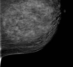
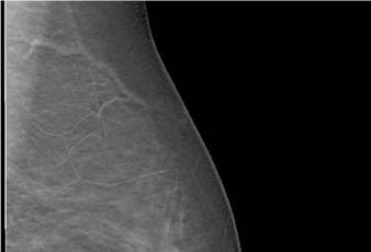
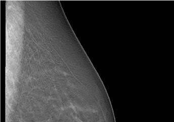
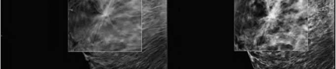
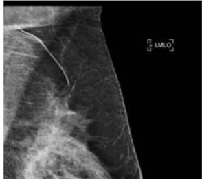
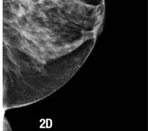
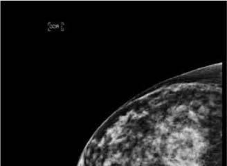
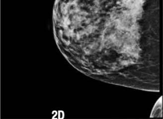
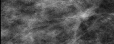
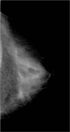
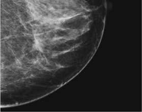
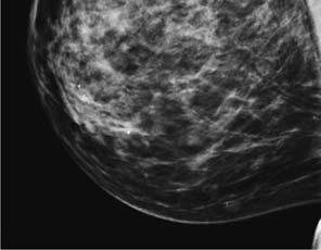
9 DIGITAL BREAST TOMOSYNTHESIS DBT Topics What is breast tomosynthesis? Why do breast tomosynthesis? How does breast tomosynthesis work? How do we use it clinically? Clinical examples What is its clinical performance? Summary of advantages 2D mammography image with a suspicious area identified and enlarged RMLO 9 2D


10 2D 3D 2D 3D February D universal driver s license Toyota Ford BMW Chevy Cadillac MD, MP, RT all need 8 hours of modality specific training in: Hologic DBT GE DBT Siemens DBT 10


11 2D universal driver s license even though technologies are different: CR DR Indirect conversion Direct conversion 3D unique driver s license; unique features training Ford Chevy Toyota Ford Chevy Toyota BMW Cadillac BMW Cadillac 11


12 In The Beginning 3D Tomosynthesis Dataset: 2D/3D (Combo Acquisition) Arc of motion of x-ray tube, showing individual exposures February


13 Tomosynthesis Dataset: 2D/3D (Combo Acquisition) Finishing with the 2D exposure TOMO THE MOVIE PG D Mammogram Tomosynthesis 13


14 THRILLER 2D Mammogram Tomosynthesis SCI - FI 2D Mammogram Tomosynthesis IS IT REAL... OR FAKE? 14


15 2D VS 3D We are a 3 dimensional object 3. depth front/back 1. height 1. height 2. width CC MLO 15


16 Daniel Kopans M.D. Computers in the 1970s GE Research Tomo Unit Mass. General Hospital 16 Breast tomo first demonstrated by Niklason et. al. 1997


 Image slices in high")
17 Initially took 2 days to reconstruct Tomo slices 12 + Now down to 2 seconds/image for Hologic s Dimensions Tomo unit Clinical Examples Collected from six sites: Hospital Prive d Antony Paris, France MGH Boston, MA USA Dartmouth Hitchcock Medical Center Lebanon, NH USA Magee Women s Hospital Pittsburgh, PA USA Netherlands Cancer Institute AVL Hospital Amsterdam, Holland Centre de Radiologie et d Echographie du Docteur Joussier Paris, France What Is Breast Tomosynthesis? A method of imaging the breast in three dimensions (3D) Image slices are 1 mm thick (selectable) Image slices in high resolution: like mammograms


18 18 3D 2D


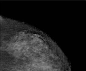
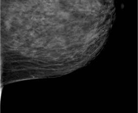
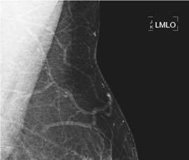
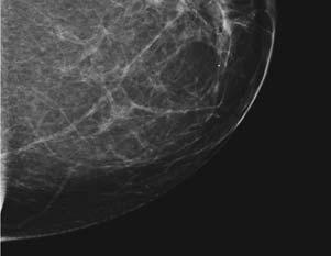
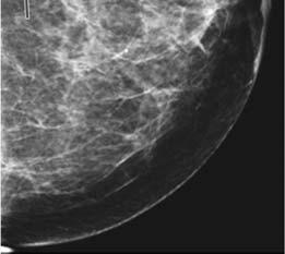
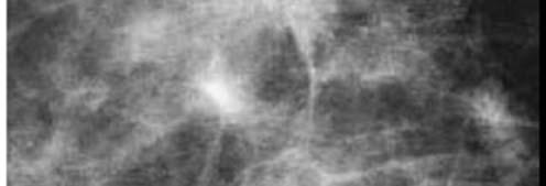
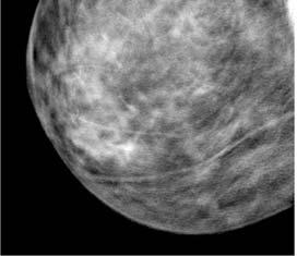
19 Why Is There A Need For 3D Tomosynthesis? Tissue superimposition hides pathologies in 2D Tissue superimposition mimics pathologies in 2D The Solution Is Tomosynthesis Tomosynthesis is a three-dimensional mammographic examination that can minimize the effects of structure overlap within the breast Why Do Breast Tomosynthesis? 2D hides cancers 2D makes normal tissue look like pathology Because 2D images have tissue superimposition Clearer images LCC 2D mammography image 19


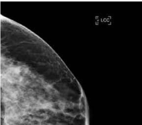
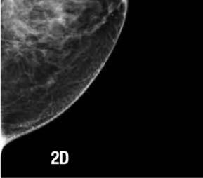
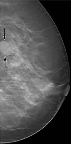
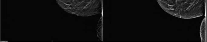
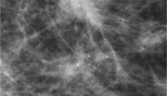
20 LCC Suspicious area in a 2D mammogram image 2D 3D 20


21 2D 3D 21


22 Does Tomo Find ca ++ Cancers? 2D 3D Tomo and ca ++ Kopans found characterization of calcifications equal or superior to 2D imaging in 92% of cases Kopans D, Moore R. Calcifications in Digital Breast Tomosynthesis (DBT) RSNA annual meeting; Chicago D 3D 22


 Masses")

23 Slice Thickness Too few: thin sharp object (ca ++ ) may not be visualized Too many: reading time increases No clinical studies to date show a benefit to less than 1mm thick slices Slabbing improves calcification cluster visibility 2D Slabbing For Calcifications Done by the radiologist at their reviewstation (Hologic) Masses viewed in 1mm slice thickness Calcifications 15mm 18mm Texas Toast 23


24 Hologic Slabbing Siemens Reconstruction Siemens Reconstruction Task performed by technologist at AWS How Does Tomosynthesis Work? Image the breast from several angles Use the multiple images to reconstruct the 3D dataset Process is very similar to CT imaging: view the body from different angles and reconstruct the volume 24
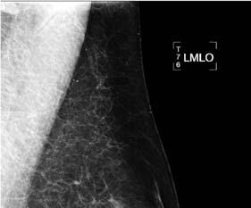
25 How Does Hologic s Tomosynthesis Work? Tube moves in a 15 0 arc 15 low dose images are acquired 1 image at each degree 4 second sweep Images are reconstructed into 1 mm slices 2 Views vs 1 View Tomo? Results 22/34 (65%) both projections equal 4/34 (12%) much better seen on MLO view 5/34 (15%) much better seen on CC view 3/34 (9%) seen only on CC view 24% In combo-mode imaging, the 2D and 3D are taken in the same compression, with no additional positioning for the patient Compressed Breast Detector Housing IMAGING IN BOTH CC AND MLO PROJECTIONS IS OPTIMAL Rafferty et.al. RSNA 2006, SSG Views vs 1 View Tomo? 8% lesions visible only on Tomo CC 1.4% only on Tomo MLO Baker JA, Lo JY. Breast Tomosynthesis: State-of-the art and Review of the Literature Radiology 18:10, (2011) 54% seen equally well on both views Of 46% seen on one view 7% seen on one view but not on other view 39% better seen on one view only April 2013 ARRS Washington DC Conference. Dr. Nora Beck 1 vs 2 DBT VIEWS? (CC vs CC + MLO) More cancers detected when 2 DBT views performed (Rafferty, RSNA 2006) Reading Time: significantly more images than with 2D Cine Tomo (transverse) arc is between Cannot generate orthogonal multi-planar reconstructions as in CT or MRI (sagittal, coronal, transverse) 25
 (@20%")
 (@65%) Subtypes: Tubular (2% 4%) Colloid/Mucinous (2%)")
 LOBULAR IN SITU (LCIS) Not a true cancer")


26 WHICH CANCER IS USUALLY FOUND IN THE CC POSITION? 25 BREAST CANCER CLASSIFICATIONS DUCTAL IN SITU (DCIS) cancers) Comedo Micropapillary Cribriform Solid Papillary INVASIVE (IDC) Subtypes: Tubular (2% 4%) Colloid/Mucinous (2%) Medullary (5%) Cribriform (3%) Papillary (2%) Inflammatory (1% 5%) No special type (NST) LOBULAR IN SITU (LCIS) Not a true cancer INVASIVE (ILC) (@10%) NIPPLE Paget s disease (1% 2%) With in situ With invasive ductal UNDIFFERENTIATED CA RARE TYPES OF MALIGNANCIES NOT CONSIDERED CARCINOMA Cystosarcoma Phyllodes Benign phyllodes Malignant phyllodes Angiosarcoma Primary breast lymphoma LOBULAR CARCINOMA 10% of all cancers 26


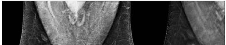
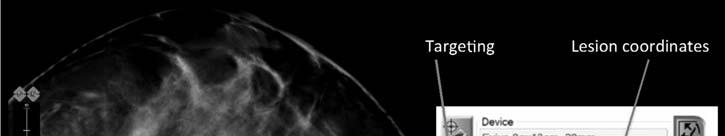
27 High Risk Patients 2 cancers found only with Tomosynthesis 6 more visible with Tomosynthesis 5 of these 8 patients had infiltrating cancers 3 had lobular cancers April 2013 ARRS Washington DC Conference. Dr. Reni Butler Combo-mode: Tomo + 2D Digital Image CC + MLO views Position breast/compress Tomo exposures Grid insertion 2D Digital mammogram Release compression The patient is positioned only once. This way you can correlate between objects in these 2 different image sets Combo Mode Co-registered 2D & 3D images Radiologist reviewstation allows rapid switching between 2D & 3D modes to facilitate image review Co-registered 2D image 27


28 Co-registered 3D image Benefits of the Combo-mode * The ROC analysis demonstrated that 2D plus 3D is superior to 2D alone The ROC results showed that for a given sensitivity, the recall rate should be lower using tomosynthesis The ROC results showed that at a given recall rate, sensitivity should be higher using tomosynthesis The ROC analysis demonstrated that the performance of all participating radiologists improved, regardless of experience None of these statements could be said for the transition from Analog to Digital Mammography * The Hologic Selenia Dimensions clinical studies presented to the FDA as part of Hologic s PMA submission that compared Hologic s Selenia Dimensions combo mode to Hologic 2D FFDM 28
: a prospective comparison study Lancet Oncology 2013 Aprl:doi:10.")
29 2D + 3D 2D 2D + 3D 2D + 3D MLO 2D Combo Mode Sensitivity 1/3 Cancers missed in 2D but found with combo mode Ciatto S, Houssaml N, Bernardi D, Caumo F, Macaskill P. Integration of 3D digital mammography with tomosynthesis for population breast cancer screening (STORM): a prospective comparison study Lancet Oncology 2013 Aprl:doi: /SO (08)


 for ca ++ approved")
30 Impact On The Radiologist 2.16 minutes to read a Combo exam 1.8 minutes to read a 2D digital exam 45 = difference in exams read in an 8 hour workday Zuley et.al. Acad Radiol 2010; 17: Analog to FFDM 50% longer DBT increases reading time by an additional 15% - 25% Longer time to read a screening exam Shorter time to read a diagnostic exam 30 CAD For Tomo 2D: useful with calcifications plus mass lesions 3D mass lesions easily identified on Tomo ciné calcification CAD scout image (slabbed) identifies cluster; then highlights to appropriate slices 3D CAD (Hologic) for ca ++ approved by CE in Europe since 2011; not yet in USA CAD approved for C-View (Hologic)

31 CAD For Tomo Challenges What format of images to send to PACS: raw, processed projections, or reconstructed slices In what format are CAD results encoded Requires extensions to DICOM M CAD Structured Report Object How do display systems interpret & render CAD marks to present to the radiologist Interoperable manner among 3 rd party vendors PACS Storage Space 1 Scan = 1.2 GB data set for a 4 view Tomo mammogram 2D digital mammogram = 88 MB = 1317 MB CXR = 8 MB (more about this later!) Conventional 2D Imaging Tomosynthesis Acquisition Objects superimposed on image Incident x-rays Objects being imaged are at different heights 2D image 31 X-ray tube Reconstructed planes Compression plate Breast Digital detector X-ray tube moves in an arc across the breast Series of low dose images are acquired at different angles Total dose similar to single view mammogram


32 Tomosynthesis Acquisition Tomosynthesis Reconstruction Image from multiple angles Incident x-rays Objects being imaged 2D raw data images Appropriate shifting and adding of raw data reinforces objects at a specific height Exposure #1 Exposure #8 Exposure #15 Projection Images Projection Images Raw Data: 15 low dose mammograms viewing breast at slightly different angles 32


: high in planes parallel to detector; considerably lower resolution in")
33 Reconstructed Images Reconstructed Images Thinner breast Thicker breast Reconstruction: crosssectional slices, one per mm of compressed breast thickness Reconstruction Of Image Algorithm similar to CT reconstruction Only data from plane of interest is displayed, while data from remaining planes blurred due to misregistration 5cm compressed breast = 55 1mm thick slices View as individual plane image or as ciné loop Tomosynthesis Reconstruction Reconstruction algorithm uses the different location in the projections of the same tissue to capture their vertical position, thereby estimating the 3D distribution of the tissue Due to a limited number of projection acquisitions, Tomo characterized by ASR (anisotropic spatial resolution): high in planes parallel to detector; considerably lower resolution in perpendicular direction 33
: high in planes parallel to detector;")


34 Tomosynthesis Reconstruction ASR (anisotropic spatial resolution): high in planes parallel to detector; considerably lower resolution in perpendicular direction ASR: view this way not this way! Hologic FDA approval available outside USA GE SenoClaire FDA approval 26 August 2014; approved in Europe July 2014 GE SenoClaire DBT FDA approved for screening & diagnostic exams FDA approved for 2D CC view & 3D MLO 34


35 2 Views vs 1 View Tomo? GE SenoClaire DBT FDA approved for screening & diagnostic exams FDA approved for 2D CC view & 3D MLO FDA approved as non-inferior to 2D GE Reader Study (MLO only) 35


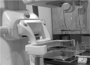
36 GE SenoClaire DBT FDA approved for screening & diagnostic exams FDA approved for 2D CC view & 3D MLO FDA approved as non-inferior to 2D Reader study: 41% longer to interpret than bilateral 2D Reader study: 16% reduction in recall rate Grid left in place during Tomo sweep GE SenoClaire DBT Grid left in place during Tomo sweep 2D 3D GE SenoClaire DBT Grid left in place during Tomo sweep GE SenoClaire DBT 2D It s a bit more complicated Than exchanging an analog 18X24cm Bucky for a 24X30cm Bucky! 36 $$$$ digital detector exposed


37 GE SenoClaire DBT #1 2D 3D MTD #2 #3 37


38 #4 #5 #6 #7 #8 #9 #13 #10 #11 #12 38
 Convert 2D machine into 3D: Press")


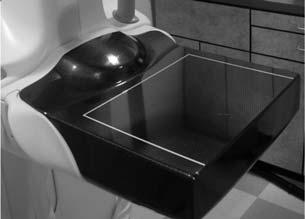
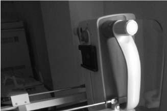
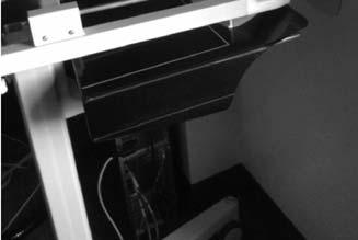
39 White compression device used for thinner breasts (4.5cm or less) Convert 2D machine into 3D: Press button Use Tomo compression device Step on footpedal Blue for thicker breasts No flex paddle for Tomo 2D patient handle 3D patient handle GE SenoClaire Step & shoot 10 second sweep, 9 exposures Screening approval: 2D CC, 3D MLO FDA approval: equivalent to 2D Upgrade to Senographe Essential; new hardware & software RT must attach a 23# device to unit in order to do 3D MLO view; remove to do mags/spots Compatible with GE Centricity PACS, IDI workstation, and Centricity Clinical Archive package 39


40 Siemens FDA approval 21 April 2015; approved in Europe, Asia, S. America


41 Siemens SNR but MTF parallel to x-ray source movement 25 projection images; 20 second scan time 50 0 arc 75 seconds between exposures FDA approval like Hologic: can do 2D & 3D Siemens No grid Computer reconstruction algorithm (PRIME) Leaves intact primary radiation Identifies scatter-causing structures and recalculates image 2D 41


42 Giotto Prototype unit PLANMED PHILIPS Prototype unit 42
43 PHILIPS 2D and 3D Multi-slit linear detector with collimated x-ray fan beam Low scatter so no grid used Eventually hope to provide energy resolution: simultaneous acquisition of 2 images using low & high energies No CR-Based Platform Images acquired every second need a high quantum efficiency detector with low noise Unable to exchange cassettes as rapidly as exposures are acquired Unable to make analog mammography machine make rapid exposures Two Designs Step and shoot Continuous motion 43
44 Image Acquisition Mode Step-and-shoot: stationary tube during exposure so no focal spot blur Mechanically challenging Focal spot blur if tube shakes Preserves sharp ca ++ since tube stops during the 9 exposures Image Acquisition Mode Step-and-shoot: stationary tube during exposure so no focal spot blur Mechanically challenging Focal spot blur if tube shakes Preserves sharp ca ++ since tube stops during the 9 exposures Continuous motion: requires short pulse width to avoid blur High ma generator (200 rather than 100) X-ray filter selection (AL) X-ray target selection (W rather than Mo) Image Acquisition Mode Step-and-shoot acquisition takes longer (10 seconds), increasing probability of patient motion Continuous motion acquisition occurs as the tube is moving, reducing spatial resolution Source: (1) N.W. Marshall and H. Bosmans, Medical Physics UZ Leuven, Application of the draft EUREF protocol for Quality Control of digital breast tomosynthesis (DBT) systems, BHPA Arc Of Motion Not linear, an ellipse, or a circle like CT. Breast anatomic structures go from nipple to chest wall so the arc is a better pattern to use With a larger arc ( ) it is harder to avoid patient collisions, especially in the CC view With a larger arc it is harder to get a fast scan, which is important to avoid patient motion


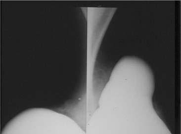
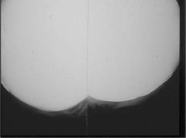
45 Arc of Motion Potential Clinical Advantages Of Tomosynthesis Better sensitivity Fewer recalls Improved visibility Fewer biopsies Benefit with dense breast Reduced dose Better Sensitivity Removal of confusing overlying tissue makes for clearer imaging Better Sensitivity ACR phantom imaged with 4cm cadaverous breast Phantom has low contrast fibers, masses, and calcifications Overlying breast tissue obscures object visibility 45


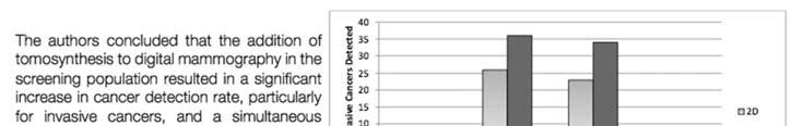
46 Better Sensitivity Slice at plane of phantom insert Tomosynthesis shows improved low contrast visibility over digital mammography Tomo Clinical Performance RSNA 2007 E Rafferty, L Niklason, et al. Assessing Radiologist Performance Using Combined Full Field Digital Mammography and Breast Tomosynthesis Versus Full Field Digital Mammography Alone: Results of a Multi Center, Multi Reader Trial 1083 women imaged 316 women in reader study with 12 radiologists Study performance 2D vs. 2D+3D Sensitivity (cancers with BIRADS 4&5) increase 66% to 76% Specificity (normals with BIRADS 1-3) increase 81% to 89% Recall rate reduced by 43% Clinical Performance Issues TMIST Multivendor, randomized clinical trial designed by ACR, ACS, NCI, ECOG- ACRIN 30 + sites; 5 years; 67,000 women Undergo either 2D only or 3D only NOT both 3 year followup Primary aim: to compare # of advanced (stage II or higher; 6 + mm aggressive tumors) cancers detected with 3D vs 2D 46 Clinical Application of DBT Screening/diagnosis Contrast enhancement: angiogenesis Multimodality imaging DBT + automated ultrasound University of Michigan DBT + optical tomography MGH DBT + limited angle SPECT University of Virginia


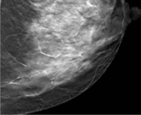
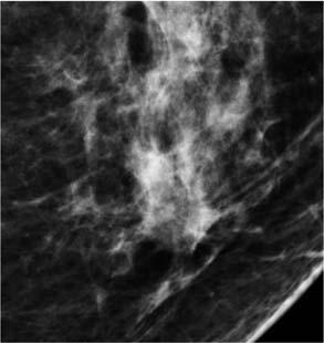
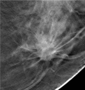
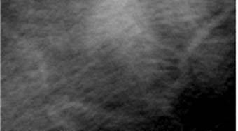
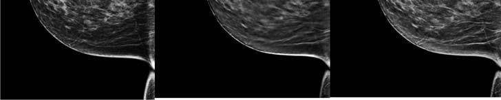
47 Potential Clinical Advantages Of Tomosynthesis Better sensitivity Fewer recalls Improved visibility Fewer biopsies Benefit with dense breast Reduced dose Fewer Recalls Removal of confusing overlying tissue makes for clearer imaging 2D imaging has imaginomas that disappear on additional views The largest published consecutive case series of such findings reports that over 80% represent summation artifact Sickles July 2012 SBI forum post 2D Mammogram Tomosynthesis RCC 2D mammography image with a suspicious area identified next to a 3D image set Fewer Recalls 47 2D

:616-623 As you go thru the image set, you see that the suspicious area is nothing more than normal breast structures overlapping Single institution of 125 selected studies 2D alone")
48 Slice Fewer Recalls Multi-center trial of 1957 patients Compared 2D & DBT. Recall rates: 43% reduction Rafferty et.al. RSNA 2007: SSG01-01 Single institution trial of 98 patients Compared 2D & DBT. Recall rates: 40% reduction Poplack et.al. AJR 2007; 189(3): As you go thru the image set, you see that the suspicious area is nothing more than normal breast structures overlapping Single institution of 125 selected studies 2D alone DBT alone: 10% reduction Combo mode: 30% reduction Gur et.al. AJR 2009;193: Single institution trial of 9499 patients: 38% reduction Rose SL, et al. Implementation of Breast Tomosynthesis in a Routine Screening Practice: An Observational Study. AJR June % reduction in recalls Ciatto S, Houssaml N, Bernardi D, Caumo F, Macaskill P. Integration of 3D digital mammography with tomosynthesis for population breast cancer screening (STORM): a prospective comparison study. Lancet Oncology 2013 Apr:doi: /SO (08) Potential Clinical Advantages Of Tomosynthesis Better sensitivity Fewer recalls Improved visibility Fewer biopsies Benefit with dense breast Reduced dose


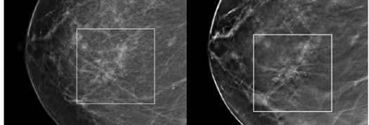
49 Improved Visibility Invasive Ductal Carcinoma (IDC) Reduced superimposed tissue improves visibility Visibility can be superior even at lower dose Tubulolobular Adenocarcinoma 2D 3D 49


50 2D 3D Potential Clinical Advantages Of Tomosynthesis Better sensitivity Fewer recalls Improved visibility Fewer biopsies Benefit with dense breast Reduced dose Expect Fewer Biopsies Tomosynthesis Biopsy Current: 5 Bx for each cancer discovered 11% reduction in biopsy rates 15.2/1000 to 13.5/1000 Rose SL, et al. Implementation of Breast Tomosynthesis in a Routine Screening Practice: An Observational Study. AJR June June 2013 Hologic Proprietary For Educational Purposes Only rev001 PRE 00379


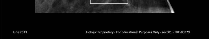


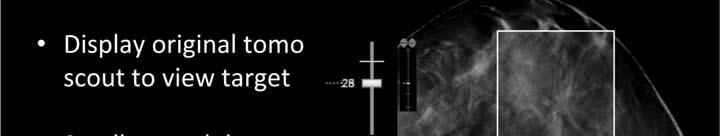
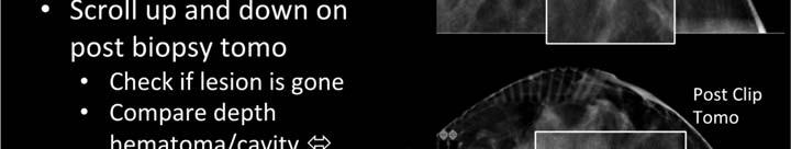
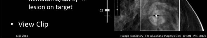
51 June 2013 Hologic Proprietary For Educational Purposes Only rev001 PRE Prefire Postfire Post Clip Tomo June 2013 Hologic Proprietary For Educational Purposes Only rev001 PRE June 2013


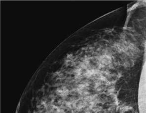
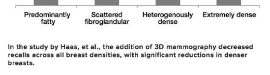
52 Potential Clinical Advantages Of Tomosynthesis Better sensitivity Fewer recalls Improved visibility Fewer biopsies Benefit with dense breast Reduced dose June 2013 Hologic Proprietary For Educational Purposes Only rev001 PRE Expect Benefit With Dense Breast ACRIN/DMIST stated FFDM better than analog for imaging the dense breast Ability to do 1mm slices negates superimposition of structures Missed cancer in dense breast as high as 52-76% Kolb TM, Lichy J, Newhouse JH. Comparison of the performance of screening mammography, physical examination, & breast us, and evaluation of factors that influence them: analysis of 27,825 patients. Radiology 225, , Dense Breast Benefit 2 3X increase in cancer detection in dense breasts Rafferty EA, Niklason L, Smith A. Comparison of FFDM with Breast Tomosynthesis to FFDM Alone: Performance in Fatty and Dense Breasts. Tomosynthesis Imaging Symposium, Duke University % of cancers found with Tomosynthesis had dense breast tissue VS 21% of cancers found with 2D only April 2013 ARRS Washington DC Conference. Dr. Jaime Geisel


53 Dense Breast Benefit Unexpected Benefit Unexpected Benefit 53


 N.W. Marshall and H.")

54 Potential Clinical Advantages Of Tomosynthesis Better sensitivity Fewer recalls Improved visibility Fewer biopsies Benefit with dense breast Reduced dose DBT Dose DBT Dose 15 projections = 1.45mGy Each 10% of a 2D image GE SenoClaire Hologic Selenia Dimensions Siemens 3D Mammo RADIATION Source: (1) N.W. Marshall and H. Bosmans, Medical Physics UZ Leuven, Application of the draft EUREF protocol for Quality Control of digital breast tomosynthesis (DBT) systems, BHPA
55 DBT Dose: PROs & CONs Benefits outweigh risk Dose within MQSA regulations Dose less than yearly background radiation Reduced need for additional views Increased sensitivity & accuracy may allow earlier detection Dose too high Combo mode is twice the dose May introduce concern regarding effects of yearly interval imaging Breast tissue already susceptible from other modalities (eg. CT) Radiation Dose Dose (50/ cm breast) MQSA = 3 mgy 2D~ 1.2 mgy (Tungsten) 3D~ 1.45 mgy Combo ~ 2.65 mgy FFDM ~ 1.6 mgy (Molybdenum) Screen/Film (ACRIN ~ 2.0 mgy average) FDA MQSA Dose Limit Phantom Dose (mgy) American College Of Radiology Phantom Dose: Single Exposure Effective 2.5 Dose (msv) Comparison Of Cumulative Whole Body Doses D 2D plus 3D MLO 2D plus 3D 0 2D 2D plus 3D Average Annual Background US Average Annual Background Colorado 55


 image Upgrade to existing Dimensions unit: C-View software module Used")
56 Radiation Dose: 2D plus 3D Tomosynthesis The additional effective dose of 3D tomosynthesis is equivalent to about 2 months of annual natural background radiation in the United States This is less than natural variations in background radiation Risk from these levels of radiation is low For example, breast cancer incidence is lower in Colorado versus the average US, even though natural background radiation is higher Reduced Dose Solution Hologic: C-View GE: V-Preview Which is Which? Synthetic View 24 Oct 2012 FDA Advisory Panel approved: 9 to 1 in favor; formal approval 21 May 2013 Created by collapsing 3D image set MIP (Maximum Intensity Projection) image Upgrade to existing Dimensions unit: C-View software module Used in Europe since 2011 May 2014 Hologic Proprietary - For Educational Use Only - rev003 PRE


57 Generating 2D Images Perform a standard tomosynthesis scan Generating 2D Images Perform a standard tomosynthesis scan Reconstruct tomosynthesis slices 55 Tomosynthesis Slices* Reconstruction Algorithm *Average slices based on 5 cm compressed breast 15 Projection Images May 2014 Hologic Proprietary - For Educational Use Only - rev003 PRE May 2014 Hologic Proprietary - For Educational Use Only - rev003 PRE Generating 2D Images Perform a standard tomosynthesis scan Reconstruct tomosynthesis slices Synthesize 2D image Available in any tomosynthesis view 55 Tomosynthesis Slices* Software Algorithm Generated 2D Images Facilitates current to prior exam review Maintains important details from tomosynthesis slices Interpreted in combination with tomosynthesis images *Average slices based on 5 cm compressed breast Generated 2D Images May 2014 Hologic Proprietary - For Educational Use Only - rev003 PRE May 2014 Hologic Proprietary - For Educational Use Only - rev003 PRE-00380


58 2D Image Comparison Tomo Slice Generated 2D 2D Image Comparison Tomo Slice Generated 2D June 2013 Hologic Proprietary For Educational Use Only rev002 PRE May 2014 Hologic Proprietary - For Educational Use Only - rev003 PRE D Image Comparison Tomo Slice Generated 2D Dose Comparison Combo Mode Tomo + FFDM 10 second scan time ACR dose = 2.65 mgy Tomo HD Mode Tomo generated 2D 4 second scan time ACR dose = 1.45 mgy May 2014 Hologic Proprietary - For Educational Use Only - rev003 PRE


59 C-View CAD $ Reimbursement for CAD used with the synthetic image is approved GE: V-Preview A navigation tool NOT intended for diagnostic use Has not been shown to be equivocal to FFDM NOT intended to replace the 2D FFDM view Hologic Phantom 30 kvp 70 mas W target Al filtration 1.45 mgy = dose GE DBT Uses a grid in 3D Reduces scatter Preserves dose & performance Dose of 3D view is equivalent to that of a standard 2D acquisition of the same view NO grid used with Tomo images, although they are working on a grid 59


60 Implants 60


61 ESSENTIAL AND BASIC; SPECIFIC PRACTICAL DETAILS 61


62 62


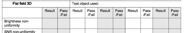
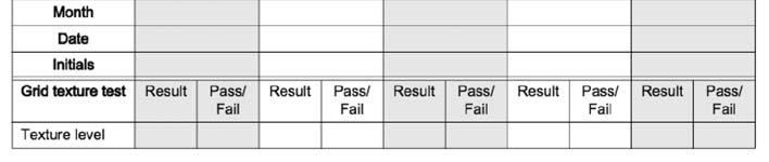
63 DBT QC QC Tests Tomo approved by FDA on 11 February 2011 First unit installed at Massachusetts General Hospital As with digital mammography, the manufacturer determines the QC tests Hologic 63 7 Weekly 1 Biweekly 1 Monthly 1 Quarterly» 2 Semi annual
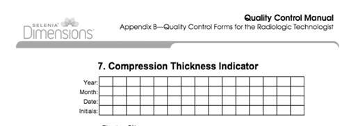
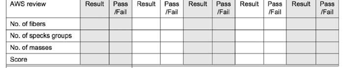
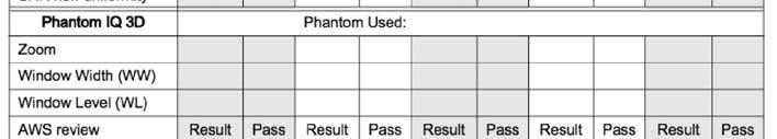
64 Quality Control Tests Quality Control Differences 2D QC 1. DICOM Printer Quality Control SMPTE 2. Detector Flat Field Calibration 3. Artifact Evaluation: Printer 4. Artifact Evaluation: Detector 5. Phantom 6. SNR CNR 7. Compression Thickness Indicator 8. Diagnostic Review Workstation 9. Viewboxes & Viewing Conditions 10. Visual Checklist 11. Repeat/Reject Analysis 12. Compression Force 3D QC 1. Detector Flat Field Calibration 2. Geometry Calibration 3. Artifact Calibration: Detector 4. Phantom 3D Tomosynthesis QC Differences Detector Flat-Field Calibration (Gain Calibration) 5 additional exposures for the Tomosynthesis Gain Calibration with Al (aluminum) filter Geometry Calibration 1 exposure Artifact Evaluation 1 additional Tomosynthesis Artifact Evaluation image Phantom Image Quality Evaluation 1 additional Tomosynthesis Phantom image (Combo exposure vs a 2D exposure) 64 DICOM PRINTER QC FREQUENCY: Weekly OBJECTIVE: To assure consistency of DICOM printer performance EQUIPMENT: Densitometer SMPTE test pattern


65 DICOM PRINTER QC Measure the OD of the 10%, 40%, and 90% SMPTE patches and plot accordingly Consistency over time proves printer stability Also perform after PM, service, and/or software changes to either the printer or to the mammography unit; validates interface configuration integrity DETECTOR FLATFIELD CALIBRATION FREQUENCY: Weekly OBJECTIVE: To assure that the system is calibrated properly EQUIPMENT: 4cm acrylic block 65


66 Contact Mode Magnification Mode set at 5 7cm set at 5 7cm 1.8 mag factor 66


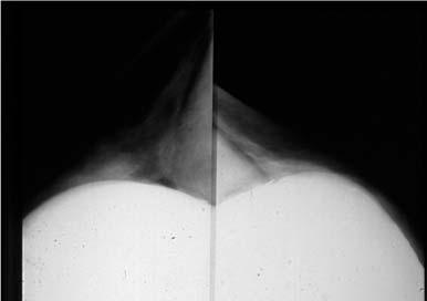
67 GEOMETRY CALIBRATION GEOMETRY CALIBRATION FREQUENCY: Semi-annual OBJECTIVE: To assure that the system is calibrated properly EQUIPMENT: Geometry phantom 20# compression force Geometry calibration is performed automatically by software on the AWS Embedded lead beads in each level of the paddle should project to an exact X/Y position in the detector System performs automatic validation Test will fail if lead does not project as expected 67


68 ARTIFACT EVALUATION (printer + x ray unit) FREQUENCY: Weekly OBJECTIVE: To assure that the image is free of undesirable artifacts EQUIPMENT: 4cm acrylic block Printer DICOM PRINTER ARTIFACT EVALUATION SYSTEM ARTIFACT EVALUATION 8 X 10 inch film 10 X 12 inch film Examine film(s) for artifacts Rh filter Ag filter Tomo with Al filter View images on AWS monitor for artifacts set at 5-7cm 68

 Image acquisition Image")


69 Artifact Evaluation Actual Pixel button to display 1:1 display mode (1 detector pixel to 1 monitor pixel) Image acquisition Image review PHANTOM IMAGE FREQUENCY: Weekly OBJECTIVE: To assure that image quality due to the x-ray imaging system and DICOM printer are maintained at optimum levels EQUIPMENT: Phantom with disc 69 1 (Combo) exposure but do 2D & 3D scoring Auto-Filter; AEC sensor position #2; apply minimal compression

 Masses (4.")

 Masses (3.")


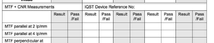
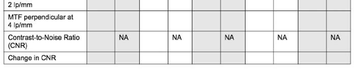
70 2D 2D Criteria: Fibers (5.0) Specks (4.0) Masses (4.0) Tomosynthesis Criteria: Fibers (4.0) Specks (3.0) Masses (3.0) Score on AWS monitor D Score on AWS monitor SNR/CNR MEASUREMENTS FREQUENCY: Weekly OBJECTIVE: To assure consistency of the digital image receptor by evaluating the SNR and CNR of the image receptor EQUIPMENT: Phantom with disc 70


71 Automatic method Manual method COMPRESSION THICKNESS INDICATOR FREQUENCY: OBJECTIVE: To assure that the indicated compression thickness is within tolerance EQUIPMENT: Phantom Spot compression device 71


72 COMPRESSION THICKNESS INDICATOR Compressed breast thickness used to determine AEC dose parameters GE Senoclaire 72


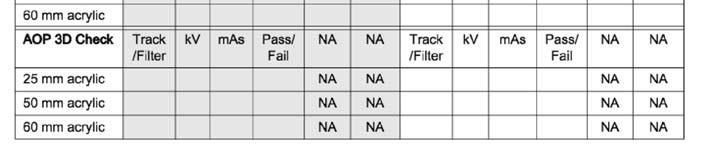
73 (score 2D only; must have MTD in place) 2D/3D


74 2D 3D IQST device IQST device 74


75 one exposure; non-uniformity MTD in place 75


76 76


77 77

 2D Digital Mammography 2000-2011 Gold standard Low dose Grayscale images Black = adipose tissue White = glandular tissue,")
78 DIGITAL MAMMOGRAPHY 1924 FILM 1972 S/F 2011 DBT 201? Radiology has been digital since 1981; mammography since 2000 FFDM may be slightly better at detecting cancer than analog imaging, however its primary advantages are logistical Storage Portability Dynamic image Stepping stone to future trends in BrCA detection Analog Mammography Gold standard Low dose Grayscale images Black = adipose tissue White = glandular tissue, cancers Gray = everything else 2D Multiple views (CC, MLO, ML, LM, etc) 2D Digital Mammography Gold standard Low dose Grayscale images Black = adipose tissue White = glandular tissue, cancers Gray = everything else 2D Multiple views (CC, MLO, ML, LM, etc) TOMOSYNTHESIS SCREEN/FILM FFDM Analog Imaging 100 shades of gray superimposition 78


79 TOMOSYNTHESIS SCREEN/FILM FFDM TOMOSYNTHESIS SCREEN/FILM FFDM SCREEN/FILM TOMOSYNTHESIS SCREEN/FILM FFDM FFDM 2D Digital Imaging 16,384 shades of gray superimposition 3D 16,384 shades of gray NO superimposition TOMOSYNTHESIS DBT CHALLENGES : Clinical What clinical uses are appropriate for this new technology? Is it a screening tool? Should it be used selectively during the diagnostic workup? Should this be used only on women with dense breast tissue? What do we do about patients with implants? Mosaic/tiled breasts? Do we compress the same as with 2D? LET S TALK ABOUT COMPRESSION TBD 79


80 COMPRESSION 2D 3D Mass Conspicuity COMPRESSION Reduces thickness of X no breast Uniform penetration X no Separate glandular tissue X no Reduce geometric X no unsharpness Improve contrast X no Radiation dose constant 4cm and 6cm phantoms 12.5% reduction in compression thickness Less motion X X Reduce patient dose X X Can Compression Be Reduced For Breast Tomosynthesis? R. Saunders, et al. June 2009 Radiology, 251, CA ++ Conspicuity COMPRESSION Radiation dose constant 4cm and 6cm phantoms 12.5% reduction in compression thickness Can Compression Be Reduced For Breast Tomosynthesis? R. Saunders, et al. June 2009 Radiology, 251, REDUCE COMPRESSION BY 50% Reduction of force of compression by 50% without losing any important diagnostic information More noise in thickest portion of breast, but presented no difficulty for readers Oblique view, pectoral muscle area Fornvik D, Andersson I, Svahn T, Timberg P, et al. The Effect of Reduced Breast Compression in Breast Tomosynthesis; Human Observer Study Using Clinical Cases. Radiation Protection Dosimetry, 139, , 2010
 Must have")


 displays increased contrast uptake Tomo image overlaid")
81 REDUCED COMPRESSION REQUIRED CONTRAST ENHANCED MAMMOGRAPHY Contrast Enhanced Tomosynthesis (CE DBT) Must have appropriate blood flow in the breast to evaluate Pattern of blood flow Abnormal blood flow Tumor uptake of contrast material Tumor border delineation GE Senobright 81 CONTRAST ENHANCED MAMMOGRAPHY Uses iodinated contrast agent Combines functional 2D information from distribution of contrast agent & morphological information from 3D images Combine into a single fused study 2D or Tomo contrast image (like a scout image) displays increased contrast uptake Tomo image overlaid for morphological information


82 If we reduce the force of compression, what about Tomosynthesis and Motion October Hologic, Inc. All Rights Reserved rev001 PRE Introduction: Motion Unsharpness Most common patient-related artifact* Motion: local/regional or involves the entire breast Gross or Subtle Repeats for motion increase radiation dose Potential to miss breast cancer *Geiser et al: Challenges in Mammography; AJR:197, December 2011 Introduction: Motion Unsharpness Factors Contributing To Motion Unsharpness Inadequate Compression Poor Positioning Exposure Time Patient Movement Heart Motion October Hologic, Inc. All Rights Reserved rev001 PRE October Hologic, Inc. All Rights Reserved rev001 PRE-00295


 and objects should move smoothly along this same pathway Medial to Lateral /Lateral to Medial Anterior/posterior movement of the breast images or")
83 Introduction: Motion Unsharpness Tomosynthesis (3D) Motion Unsharpness Occurs at about the same frequency as conventional mammography (2D) Presents the same issues as 2D motion, EXCEPT that motion may go undetected Tomosynthesis and Motion 3D Motion May Be Unrealized And Unchecked Radiologists do not routinely review the projection dataset where motion can be confirmed or ruled-out Projection dataset may not be available to the radiologist It is up to the technologist to detect motion and repeat when advised October Hologic, Inc. All Rights Reserved rev001 PRE October Hologic, Inc. All Rights Reserved rev001 PRE REVIEW PROJECTIONS FOR MOTION Appreciating 3D Motion Projection Series The x-ray tube moves in a path parallel to the chestwall The resulting breast image(s) and objects should move smoothly along this same pathway Medial to Lateral /Lateral to Medial Anterior/posterior movement of the breast images or objects indicates motion 83 October Hologic, Inc. All Rights Reserved rev001 PRE-00295

84 Appreciating 3D Motion Arc of motion of x ray tube, showing individual exposures If objects in the breast seem to wiggle and bounce anterior to posterior, consider motion October Hologic, Inc. All Rights Reserved rev001 PRE October Hologic, Inc. All Rights Reserved rev001 PRE Appreciating 3D Motion Arc of motion of x ray tube, showing individual exposures Tomosynthesis and Motion Important notes: We do not yet understand the full impact of 3D motion on image quality and when repeat is necessary Motion can occur at one point, multiple points or through-out the duration of the entire projection series Motion can occur at different areas of the breast, which may or may not impact breast tissue May affect conspicuity, sharpness of detail 2012 Hologic, Inc. All rights reserved. October 2012 PRE October Hologic, Inc. All Rights Reserved rev001 PRE-00295


85 OTHER REASONS FOR UNSHARPNESS Geometric Blurring Focal spot size Focal spot image detector distance (SID) Object image receptor distance (OID) Pixel size Motion Blurring Inadequate compression Length of exposure time OTHER REASONS FOR UNSHARPNESS Geometric Blurring Focal spot size Focal spot image detector distance (SID) Object image receptor distance (OID) Pixel size Motion Blurring Inadequate compression Length of exposure time Often times technologists/radiologists say Tomo images often display motion Is it truly motion or is it geometric blur? MTF vs SPATIAL RESOLUTION MTF preferred measure of image sharpness Spatial resolution defines one point on MTF defines where you can t see any more information, usually 8 to 10 lp/mm or more Response of eye best at 1 to 5 lp/mm Eye lacks the ability to detect 5 lp/mm beyond 50 cm, 10 lp/mm at 25 cm Spatial Resolution 85


86 Hologic DBT 3 + lp/mm GE/Siemens 5/5.8 lp/mm FFDM 9-10 lp/mm S/F lp/mm MAMMOGRAPHY Spatial Resolution S/F: lp/mm FFDM: 9-10 lp/mm DBT: 3 + lp/mm Hologic; 5 lp GE; 5.8 lp Siemens FFDM has greater contrast resolution compared to S/F DBT has better contrast resolution and eliminates superimposition of structures compared to S/F DQE is preferred method to judge image quality Comparison of ACR Phantom Scores TRADE-OFF: RESOLUTION vs READ-OUT TIME 86


 &")


87 TRADE-OFF: RESOLUTION vs READ-OUT TIME Binning Summation of multiple smaller pixels to generate a larger signal 2 X 2 Decreases read-out time Decreases noise Decreases spatial resolution Detector able to switch seamlessly between binned (3D) & non-binned (2D) states Reduces resolution 25MP reduced to 6MP Advantage = faster scan time TRADE-OFF: RESOLUTION vs READ-OUT TIME Reduces resolution 25MP reduced to 6MP Advantage = faster scan time 87 HOLOGIC DETECTOR DESIGN Optimized for DBT Reduced reading cycle time by replacing di-electric/se layer at top of Se surface with a charge conductive layer Eliminates charge-trapping - which required additional erase cycle between acquisitions 2X2 binning permits readout time to the subsecond level with minimal ghosting


 Pixel size Motion")


88 TRADE-OFF: RESOLUTION vs READ-OUT TIME Binning Hologic bins: 2 vertical + 2 horizontal Siemens does not bin GE does not bin OTHER REASONS FOR UNSHARPNESS Geometric Blurring Focal spot size Focal spot image detector distance (SID) Object image receptor distance (OID) Pixel size Motion Blurring Inadequate compression Length of exposure time Often times technologists/radiologists say Tomo images often display motion Is it truly motion or is it geometric blur? ARTIFACTS 1 overshooting streak/slinky 88 October Hologic, Inc. All Rights Reserved rev001 PRE-00295


89 ARTIFACTS Severity of out-of-plane artifact dependent upon size of the ca ++, titanium tissue marker clip, etc. Overshoot artifact is a void of information caused when the filtering process extends beyond the border of the sampled region 89


90 SYSTEM SPECIFICATIONS & DESIGN PARAMETERS SYSTEM SPECIFICATIONS Pixel: 70 micron Spatial resolution: 2D = 9 lp/mm 3D = 3 + lp/mm 14 bit depth Constant potential generator 200 ma LFS / 50 ma SFS kvp SYSTEM SPECIFICATIONS System Specifications Tungsten target x-ray tube 0.3 mm LFS; 0.1 mm SFS 16 0 angle, biangular, rotating Beryllium window Filtration: Rh = 0.05 mm Ag = 0.05 mm Al = 0.70 mm SID: 70cm 2 magnification factors: 1.5 X & 1.8 X 90


91 SYSTEM SPECIFICATIONS Pixel: 100 micron Spatial resolution: 2D = 9 lp/mm 3D = 5 lp/mm 14 bit depth High frequency, single phase generator 100 ma LFS / 30 ma SFS kvp SYSTEM SPECIFICATIONS Mo/Rh target x-ray tube 0.3 mm LFS; 0.1 mm SFS 10 0 angle Beryllium window Filtration: Mo = 0.05 mm Rh = 0.05 mm SID: 66cm 2 magnification factors: 1.5 X & 1.8 X SYSTEM SPECIFICATIONS SYSTEM SPECIFICATIONS Pixel: 85 micron Spatial resolution: 2D = 9 lp/mm 3D = 5.8 lp/mm 14 bit depth Constant potential generator 100 ma LFS / 30 ma SFS kvp Tungsten target x-ray tub 0.3 mm LFS; 0.1 mm SFS 16 0 angle, biangular, rotating Beryllium window Filtration: Rh =? mm SID: 65cm 2 magnification factors: 1.5 X & 1.8 X 91


92 DESIGN PARAMETERS dose slice thickness # projections DESIGN PARAMETERS Improves clinical performance over 2D alone 2D + 3D modes One manufacturer does 3D only Works for screening as well as diagnostic exams Supports biopsies/interventional procedures Fast scan time to reduce patient motion Rapid image reconstruction to support rapid patient throughput Ability to compare C/P Radiologist reading time short enough for screening DETECTOR OPTIMIZATION Breast Tomosynthesis is based on the principles of digital imaging It utilizes the same detector as 2D digital mammography machines, with some modifications X-ray tube rotates around a point close to or on the detector Detector with fast readout Minimal ghosting/lag; introduces image artifacts Minimal reduction in DQE at low exposures (due to dividing total exposure over several projection images) 92


93 IMAGE QUALITY Affected by: Quality of each projection Number of projections Angular range of the projections Image reconstruction algorithms QUALITY OF EACH PROJECTION Determined by dose & DQE of the digital detector We want high SNR despite the low x- ray exposure/image (1.45mGy 15 exposures) Low noise of digital detector is key factor here X-ray spectrum selected (W vs Mo/Rh) MEASURE OF IMAGE QUALITY Detective Quantum Efficiency (DQE) SNR 2 at detector output DQE = SNR 2 at detector input Measures transfer of both signal and noise DETECTIVE QUANTUM EFFICIENCY Measures system efficiency Examines process of creating image Conversion of x-rays into the resulting image 93
94 DQE and NOISE Control DQE and noise by Increasing x-rays reaching detector Efficient detection of x-rays Efficient scintillator & high pixel fill factor Efficient coupling between scintillator and photo detector Low electronic noise 1.45 mgy 15 EXPOSURES If the dose is 1.45mGy and it is 15 exposures = very few x-ray photons/exposure for computer to create each DBT slice Tomo sweep only Standard image acquisition mode used for routine imaging Enhanced image acquisition mode may be used for diagnostic exams Increases dose Use for faint microcalcifications Use for hard to see mass QUALITY OF EACH PROJECTION Determined by dose & DQE of the digital detector We want high SNR despite the low x- ray exposure/image (1.45mGy 15 exposures) Low noise of digital detector is key factor here X-ray spectrum selected (W vs Mo/Rh) SNR Image Quality Noise and quantum mottle are important Signal/noise = Signal-to-noise ratio = SNR Signal increases, SNR increases Noise increases, SNR decreases Signal Noise 94

 Low noise of digital")
 selected (W vs Mo/Rh)")


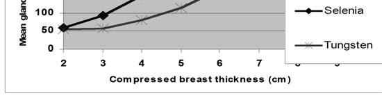
95 QUALITY OF EACH PROJECTION Determined by dose & DQE of the digital detector We want high SNR despite the low x-ray exposure/image (1.45mGy 15 exposures) Low noise of digital detector is key factor here X-ray spectrum selected (W vs Mo/Rh) QUALITY OF EACH PROJECTION Determined by dose & DQE of the digital detector We want high SNR despite the low x-ray exposure/image (1.45mGy 15 exposures) Low noise of digital detector is key factor here X-ray spectrum selected (W vs Mo/Rh) MOLYBDENUM vs TUNGSTEN Tungsten reduces dose by about 35% depending on breast thickness/density 95


96 96

 filter used in 2D for medium")
 filter used in 3D If")


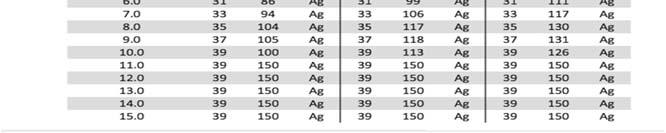
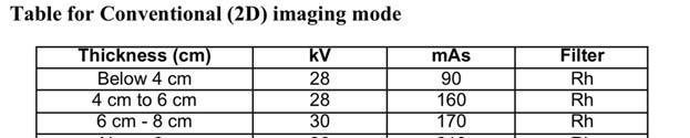
97 TUNGSTEN TARGET TUBE Rhodium (Rh) filter used in 2D for thin average size compressed breasts Silver (Ag) filter used in 2D for medium thicker compressed breasts Aluminum (Al) filter used in 3D If the dose is 1.45mGy and it is 15 exposures = very few x-ray photons/exposure for computer to create each DBT slice TUNGSTEN TARGET TUBE Imaging in the near term future Contrast enhanced mammography Dual energy imaging Lower dose Improved image quality Short exposure time to minimize Patient motion Focal spot blur during short x-ray pulses during DBT sweep 97
 if degree of separation between exposures is too far apart More exposures Fewer artifacts Less signal/pixel More noise Larger raw data file")
98 IMAGE QUALITY Affected by: Quality of each projection Number of projections Angular range of the projections Image reconstruction algorithms # OF PROJECTIONS Fewer exposures Less information to reconstruct the 3D volume Streak artifacts (like in CT) if degree of separation between exposures is too far apart More exposures Fewer artifacts Less signal/pixel More noise Larger raw data file size Longer time to reconstruct image Patient motion 98 # OF PROJECTIONS Increasing the # of projections during a Tomosynthesis acquisition increases the vertical resolution up to a certain threshold, beyond which the resolution remains constant unless the angular range is increased
99 # OF PROJECTIONS Wider scan angle: need more projections to avoid under sampling Too many: results in fixed dose divided among many projections; noise can increase Narrow scan angle: fewer required projections Too few: results in missed sampling and possible reconstruction artifacts # OF PROJECTIONS Distribution of the projections This parameter has high impact on image quality No previously established modalities that involve similar parameters from which to draw any experience Vast differences among manufacturers of this new technology WHICH TO SELECT? IMAGE QUALITY Affected by: Quality of each projection Number of projections Angular range of the projections Image reconstruction algorithms 99
 taken at different angular locations of the tube Breast")
 50 (±25 0 ) ANGULAR RANGE ANGULAR RANGE Smaller arc range Larger arc")

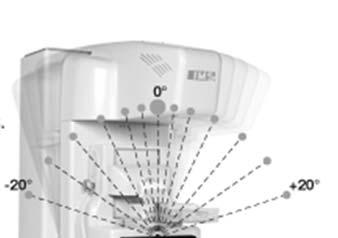
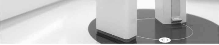
100 ANGULAR RANGE Total angular range covered by the x-ray tube Series of low dose images (projections) taken at different angular locations of the tube Breast held stationary Industry range: 15 (±7.5 0 ) 50 (±25 0 ) ANGULAR RANGE ANGULAR RANGE Smaller arc range Larger arc range Smaller arc range Larger arc range Increasing the angular range travelled during the arc of the x-ray tube consistently increases the vertical resolution Of the reconstructed Tomosynthesis image 100

101 ANGULAR RANGE Larger angular range = increased reconstruction slice separation Good for resolving 2 closely lying structures Harder to define cluster of microcalcifications versus The angular range directly affects the depth resolution. Two projections at will not be able to separate the 2 spheres. Two projections at can separate the 2 spheres due to adequate depth resolution ANGULAR RANGE Better out-of-plane resolution Worse in-plane resolution X-ray can be detected by more than 1 pixel Longer scan time ANGULAR RANGE Larger angular range directly affects depth resolution Wider arc angle = better separation of structures at different heights due to physical slice width decreases with a larger angular range Tissue overlap is reduced Out-of-plane artifacts are reduced because they are spread over a wider range in the considered plane Downside: large angular range reduces volume when using a stationary detector; loss of visualization of some tissue in each projection 101


102 ANGULAR RANGE As thickness of breast increases AND scan angle increases, the FOV on either side of the breast is cut off ANGULAR RANGE Most rapid scan time Smaller angular range keeps more structures in focus in a given slice Better for microcalcifications May not reduce overlapping structures as much as a wider scan angle ANGULAR RANGE Better in-plane resolution Worse out-of-plane resolution Sharper resolution for calcifications Faster scan time OPTIMUM ANGULAR RANGE Scan time Narrow scan angle = rapid Wide scan angle = longer time Resolution Narrow scan angle = depth of field increases so in-plane resolution is superior; better for discerning microcalcifications Wide scan angle = depth of field decreases so out-of-plane resolution is superior; better for discerning overlapping structures 102
 studied resulted in increased image quality, while the optimal number of projections")


103 WHICH TO SELECT? Repeatedly found that the widest angular ranges ) studied resulted in increased image quality, while the optimal number of projections was achieved at a relatively low number (@ 15 20) The upper limit in vertical resolution is given by angular range, and the number of projections for a specific angular range should be that which just meets the required threshold number to obtain the best possible ASR, with no benefit in a further increase Sechopoulos I. A review of Breast Tomosynthesis. Part 1. The Image Acquisition Process. Medical Physics, Vol. 40, No. 1, Jan 2013 SHORT SCAN TIME Screening examination Support reasonable patient throughput Reduce blurring from patient motion Minimize time patient is compressed IMAGE QUALITY Affected by: Quality of each projection Number of projections Angular range of the projections Image reconstruction algorithms 103


, allowing software developers to take advantage of what was learned")

104 ITERATIVE RECONSTRUCTION Iteration: the act of repeating a process with the aim of approaching a desired goal, target or result. Each repetition of the process is also called an "iteration, and the results of one iteration are used as the starting point for the next iteration. ITERATIVE RECONSTRUCTION The basic idea behind this method is to develop a system through repeated cycles (lterative) and in smaller portions at a time (incremental), allowing software developers to take advantage of what was learned during development of earlier parts or versions of the system. Learning comes from both the development and use of the system, where possible key steps in the process start with a simple implementation of a subset of the software requirements and iteratively enhance the evolving versions until the full system is implemented. At each iteration, design modifications are made and new functional capabilities are added. Iterative Reconstruction 104

")


105 FBP RECONSTRUCTION Shift-and-add is equivalent to filtered back projection (FBP) Mathematical technique called shift-andadd gives idea of spatial distribution & slices parallel to detector plane are generated By shifting the single projection views according to the height of a certain feature, the information of that feature is summed up, whereas the information of features from other heights are spreadout (misregistered) FBP RECONSTRUCTION Filtered-back-projection = CT reconstruction technique Minimal distortion & high accuracy rotation with CT; Tomo arc is Less radiation from breast Tomo sweep; high dose with CT rotation Results in a more complicated method of 3D reconstruction, especially for out-ofplane & streak artifacts FBP Reconstruction FBP RECONSTRUCTION Made up of a number of filters Ramp type filter: compensates for blurring introduced by back projection Spectral filter: reduces high frequency noise Slice thickness filter: ensures constant depth resolution; controls spatial slice sensitivity profile and suppresses out-of-plane artifacts 105


106 Siemens Reconstruction Bounding Box TOMOSYNTHESIS CHALLENGES Potential challenges Size of the data set is huge Concurrent assessment of 2D & 3D Challenges for archival & retrieval Portability of images Referring physician display capability PACS STORAGE SPACE 1 Scan = 1.2 GB for a 4 view Tomo mammogram 2D digital mammogram = 88 MB = 1317 MB 106 CXR = 8 MB


107 BANDWIDTH Amount of information that can be sent over a data channel per unit of time Rate data moves from one point to the next If too many computers are on the same network, PACS is slow 107


108 COMPRESSION Lossy Compression of data When image is reconstructed, the lost/compressed data cannot be recalled Lossless Minimal compression of data is allowed in mammography 4:1 108


 415 GB (0.")
 Annual Storage (GB/TB/Year) 830 GB (0.")
 7 Year Storage (GB/TB/7 Years) 2905 GB (2.")
 109 7 Year Storage (GB/TB/7 Years) 5810 GB (5.")
109 LOSSY COMPRESSION LOSSLESS COMPRESSION 40 pts/day Image Storage Requirements 10,000 exams/year (70% SFOV/30% LFOV; 4:1 lossless compression) Archiving for presentation only 50um CR System 70um System 100um System 7000 SFOV Exams 980,000 MB 448,000 MB 224,000 MB 3000 LFOV Exams 720,000 MB 336,000 MB 180,000 MB Total S + L FOV 1,700,000 MB 784,000 MB 404,000 MB 80 pts/day Image Storage Requirements 20,000 exams/year (70% SFOV/30% LFOV; 4:1 lossless compression) Archiving for presentation only 50um CR System 70um System 100um System SFOV Exams 1,960,000 MB 896,000 MB 448,000 MB 6000 LFOV Exams 1,440,000 MB 672,000 MB 360,000 MB Total S + L FOV 3,400,000 MB 1,568,000 MB 808,000 MB With 4:1 Lossless Compression 425,000 MB 196,000 MB 101,000 MB With 4:1 Lossless Compression 850,000 MB 392,000 MB 202,000 MB Annual Storage (GB/TB/Year) 415 GB (0.41 TB) 191 GB (0.19 TB) 99 GB (0.10 TB) Annual Storage (GB/TB/Year) 830 GB (0.81 TB) 383 GB (0.37 TB) 197 GB (0.19 TB) 7 Year Storage (GB/TB/7 Years) 2905 GB (2.84 TB) 1340 GB (1.27 TB) 693 GB (0.68 TB) Year Storage (GB/TB/7 Years) 5810 GB (5.67 TB) 2681 GB (2.62 TB) 1379 GB (1.35 TB)
110 Hologic Digital Mammography File Sizes Typical 4 View Study, Left and Right Breasts Hologic Digital Mammography File Sizes Typical 4 View Study, Left and Right Breasts 4 View Study 2D Hologic Secondary Capture Tomo Object DICOM Breast Tomo Object 4 View Study 2D Hologic Secondary Capture Tomo Object DICOM Breast Tomo Object Uncompressed 88 MB N/A(this is always compressed) 1.2GB Compressed (lossless) 22 MB 136 MB 320 MB Total Combo File Size 158 MB 342 MB Uncompressed 88 MB N/A(this is always compressed) 1.2GB Compressed (lossless) 22 MB 136 MB 320 MB Total Combo File Size 158 MB 342 MB THESE ARE AVERAGES THESE ARE AVERAGES Notes: 1.The Hologic Secondary Capture Tomo Object is already compressed and cannot be compressed further 2.Compressing image data always relies on the ability to decompress the data (PACS, SecurView) HOLOGIC PROPRIETARY SECONDARY CAPTURE OBJECT Selected by Hologic, the first to meet the challenge, as to the Tomosynthesis data format. There was no standard available at the time Only the Hologic SecurView workstation and Dimensions Mammography system can display this image data Data is already compressed for storage and network speed efficiencies Sectra; 2013 GE approved to play Tomo clip; 2014 Carestream 110 SAME FOR GE Step & shoot 10 second sweep, 9 exposures Screening approval: 2D CC, 3D MLO FDA approval: equivalent to 2D Upgrade to Senographe Essential; new hardware & software RT must attach a 23# device to unit in order to do 3D MLO view; remove to do mags/spots Compatible with GE Centricity PACS and Centricity Clinical Archive package
111 HOLOGIC PROPRIETARY SECONDARY CAPTURE OBJECT Most PACS companies can support the storage of the Secondary Capture object But not the DISPLAY at this time If sent to PACS, the PACS workstation is only able to display the middle reconstructed slice For example, if there are 50 slices, slice number 25 will be displayed. This is not for diagnostic use WHY WOULD THEY DO THIS? Why did vendor use a proprietary image file format? This hides Tomo pixel data in private attributes inside a secondary capture DICOM object with a dummy (middle frame only) image This allows storage in PACS, even obsolete ones But now user must have a system capable of deciphering and displaying this information WHY WOULD THEY DO THIS? 3 ways (Hologic) images can be viewed Hologic stores images using international DICOM standard: BTO (breast tomo objects). Any PACS that conforms to this version of the DICOM standard can play the Tomo movie Selected image slices from the Tomo movie can be saved in a Secondary Capture format. This is a standard PACS compatible format Tomo movie can be saved as an.avi movie. This is a standard format compatible with PCs 111 MAMMOGRAPHY VIEWING REQUIREMENTS Display is challenging Correct orientation Hanging multiple views with priors for comparison Annotation Display with comparable size: True size, Actual size Measurement tools Correct grayscale handling Tomo specific Smoothly scroll at rapid frame rate without skipping frames, thru all slices + all views Synchronized with same size/comparing contralateral & prior views Handle both ciné and manual scrolling

112 2D vs TOMO 2D Large matrix size per image Single frame for each view slices per view Each matrix size of FFDM image A lot of data to transmit and store MAMMOGRAPHY VIEWING REQUIREMENTS Challenge Display on computer monitor of referring physician who does not have radiologist-type review workstation CD given to patient MAMMOGRAPHY VIEWING REQUIREMENTS 3D It is not appropriate to print hardcopy DBT movie Series of printed hardcopy films cannot be used for interpretation View only as softcopy C-View (Hologic); V-Preview (GE) Must be viewed in conjunction with Tomo movie Not for diagnostic interpretation For comparison only Cannot be used for permanent transfer 2D CD Hardcopy 112
4/19/2016. Deborah Thames R.T. (R)(M)(QM) Theory & Technology and advancement in 3D imaging DBT
(M)(QM) Theory & Technology and advancement in 3D imaging DBT") Deborah Thames R.T. (R)(M)(QM) Theory & Technology and advancement in 3D imaging DBT 1 Three manufacturers approved for Tomo Hologic and GE, and Siemens Why 2D Digital Mammography 2D FFDM it appears to
Deborah Thames R.T. (R)(M)(QM) Theory & Technology and advancement in 3D imaging DBT 1 Three manufacturers approved for Tomo Hologic and GE, and Siemens Why 2D Digital Mammography 2D FFDM it appears to
10/9/2018. Deborah Thames BSRS RT (R)(M)(QM) Theory & Technology and advancement in 3D imaging DBT
(M)(QM) Theory & Technology and advancement in 3D imaging DBT") Deborah Thames BSRS RT (R)(M)(QM) Theory & Technology and advancement in 3D imaging DBT 1 Mammography Five FFDM approved for Tomo Hologic, Ge Senoclair and GE Pristina, Siemens, and Fujifilm 2 Why 2D Digital
Deborah Thames BSRS RT (R)(M)(QM) Theory & Technology and advancement in 3D imaging DBT 1 Mammography Five FFDM approved for Tomo Hologic, Ge Senoclair and GE Pristina, Siemens, and Fujifilm 2 Why 2D Digital
Unique Features of the GE Senoclaire Tomosynthesis System. Tyler Fisher, M.S., DABR Therapy Physics, Inc.
 Unique Features of the GE Senoclaire Tomosynthesis System Tyler Fisher, M.S., DABR Therapy Physics, Inc. Conflict of Interest Disclosure I have no conflicts to disclose. Learning Objectives Overview of
Design Considerations in Optimizing a Breast Tomosynthesis System
 Design Considerations in Optimizing a Breast Tomosynthesis System Andrew Smith, Ph.D., Vice President - Imaging Science, Hologic Introduction Breast tomosynthesis, also referred to as three-dimensional
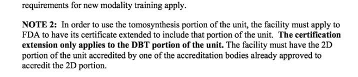
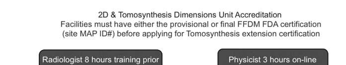
Certificate Extension II 8/1/2016. Certification Extension Process for Digital Breast Tomosynthesis and Medical Physicists Role
 Certification Extension Process for Digital Breast Tomosynthesis and Medical Physicists Role Kish Chakrabarti, Ph.D., FAAPM Division of Mammography Quality Standards Center for Devices and Radiological
8/2/2016. Hands-on GE SenoClaire DBT: technical characteristics & quality control. Disclosures and Acknowledgements
 Hands-on GE SenoClaire DBT: technical characteristics & quality control Razvan Iordache, Ph.D. GE Healthcare Imagination at work Disclosures and Acknowledgements Razvan Iordache Employee of GE Healthcare
Acknowledgments and financial disclosure
 AAPM 2012 Annual Meeting Digital breast tomosynthesis: basic understanding of physics principles James T. Dobbins III, Ph.D., FAAPM Director, Medical Physics Graduate Program Ravin Advanced Imaging Laboratories
RECENTLY APPROVED GE FFDM DBT TESTING PROCEDURES.
 RECENTLY APPROVED GE FFDM DBT TESTING PROCEDURES. S. G U R U P R A S A D, P H. D., D A B R, E M E R I T U S, M AT H E W H A L L M. S. N O RT H S H O R E U N I V E R S I T Y H E A LT H S Y S T E M A N D
Lorad FFDM QC Procedures for Medical Physicist. Tao Wu, Ph.D. Hologic, Inc.
 Lorad FFDM QC Procedures for Medical Physicist Tao Wu, Ph.D. Hologic, Inc. Lorad Selenia FFDM Tests Following Lorad QC Manual Collimation Assessment Artifact Evaluation System Resolution Phantom Image
Limitations of Projection Radiography. Stereoscopic Breast Imaging. Limitations of Projection Radiography. 3-D Breast Imaging Methods
 Stereoscopic Breast Imaging Andrew D. A. Maidment, Ph.D. Chief, Physics Section Department of Radiology University of Pennsylvania Limitations of Projection Radiography Mammography is a projection imaging
Synthesized 2D Mammographic Imaging
 Synthesized 2D Mammographic Imaging Theory and Clinical Performance Synthesized 2D Mammographic Imaging Theory and Clinical Performance Andrew Smith, Ph.D., Vice President, Image Research Hologic, Inc.,
Slide 1. Technical Aspects of Quality Control in Magnetic Resonance Imaging. Slide 2. Annual Compliance Testing. of MRI Systems.
 Slide 1 Technical Aspects of Quality Control in Magnetic Resonance Imaging Slide 2 Compliance Testing of MRI Systems, Ph.D. Department of Radiology Henry Ford Hospital, Detroit, MI Slide 3 Compliance Testing
ACMP 25th Annual Meeting
 Surveying and QC of Stereotactic Breast Biopsy Units for ACR Accreditation ACMP 25th Annual Meeting Seattle, WA May 3, 2008 Melissa C. Martin, M.S., FACR Therapy Physics, Inc. 879 West 190th St., Ste 419,
ENGLISH. Digital Breast Tomosynthesis
 ENGLISH Digital Breast Tomosynthesis Medical imaging excellence Planmed is strongly committed to improving the early detection of breast cancer. Our mission is to provide top quality imaging systems for
Assessment of 3D performance metrics. X-ray based Volumetric imaging systems: Fourier-based imaging metrics. The MTF in CT
 Assessment of 3D performance metrics D and 3D Metrics of Performance Towards Quality Index: Volumetric imaging systems X-ray based Volumetric imaging systems: CBCT/CT Tomosynthesis Samuel Richard and Ehsan
Background. Outline. Radiographic Tomosynthesis: Image Quality and Artifacts Reduction 1 / GE /
 Radiographic Tomosynthesis: Image Quality and Artifacts Reduction Baojun Li, Ph.D Department of Radiology Boston University Medical Center 2012 AAPM Annual Meeting Background Linear Trajectory Tomosynthesis
Medical Image Processing: Image Reconstruction and 3D Renderings
 Medical Image Processing: Image Reconstruction and 3D Renderings 김보형 서울대학교컴퓨터공학부 Computer Graphics and Image Processing Lab. 2011. 3. 23 1 Computer Graphics & Image Processing Computer Graphics : Create,
Digital Scatter Removal in Mammography to enable Patient Dose Reduction
 Digital Scatter Removal in Mammography to enable Patient Dose Reduction Mary Cocker Radiation Physics and Protection Oxford University Hospitals NHS Trust Chris Tromans, Mike Brady University of Oxford
Detection of microcalcification clusters by 2D-mammography and narrow and wide angle digital breast tomosynthesis
 Detection of microcalcification clusters by 2D-mammography and narrow and wide angle digital breast tomosynthesis Andria Hadjipanteli a, Premkumar Elangovan b, Padraig T Looney a, Alistair Mackenzie a,
Simulation of Mammograms & Tomosynthesis imaging with Cone Beam Breast CT images
 Simulation of Mammograms & Tomosynthesis imaging with Cone Beam Breast CT images Tao Han, Chris C. Shaw, Lingyun Chen, Chao-jen Lai, Xinming Liu, Tianpeng Wang Digital Imaging Research Laboratory (DIRL),
Digital Image Processing
 Digital Image Processing SPECIAL TOPICS CT IMAGES Hamid R. Rabiee Fall 2015 What is an image? 2 Are images only about visual concepts? We ve already seen that there are other kinds of image. In this lecture
CT Protocol Review: Practical Tips for the Imaging Physicist Physicist
 CT Protocol Review: Practical Tips for the Imaging Physicist Physicist Dianna Cody, Ph.D., DABR, FAAPM U.T.M.D. Anderson Cancer Center August 8, 2013 AAPM Annual Meeting Goals Understand purpose and importance
Shadow casting. What is the problem? Cone Beam Computed Tomography THE OBJECTIVES OF DIAGNOSTIC IMAGING IDEAL DIAGNOSTIC IMAGING STUDY LIMITATIONS
 Cone Beam Computed Tomography THE OBJECTIVES OF DIAGNOSTIC IMAGING Reveal pathology Reveal the anatomic truth Steven R. Singer, DDS srs2@columbia.edu IDEAL DIAGNOSTIC IMAGING STUDY Provides desired diagnostic
Refraction Corrected Transmission Ultrasound Computed Tomography for Application in Breast Imaging
 Refraction Corrected Transmission Ultrasound Computed Tomography for Application in Breast Imaging Joint Research With Trond Varslot Marcel Jackowski Shengying Li and Klaus Mueller Ultrasound Detection
Fujifilm DR Solution. FDR AcSelerate. The new pinnacle in diagnostic imaging from Fujifilm ISS. CsI. Dynamic Visualization. Technology.
 Fujifilm DR Solution FDR AcSelerate The new pinnacle in diagnostic imaging from Fujifilm CsI Scintillator ISS Technology Dynamic Visualization Welcome to the X-ray room of the future! A streamlined solution
AAPM Standard of Practice: CT Protocol Review Physicist
 AAPM Standard of Practice: CT Protocol Review Physicist Dianna Cody, Ph.D., DABR, FAAPM U.T.M.D. Anderson Cancer Center September 11, 2014 2014 Texas Radiation Regulatory Conference Goals Understand purpose
Planmed Sophie Classic Mobile. English. dedicated for mobile mammography
 Sophie Classic Mobile English at its best Sophie Classic Mobile proven mammography on wheels The Sophie Classic Mobile system takes transportable mammography to a new level. Generously equipped with integrated
Developments in Dimensional Metrology in X-ray Computed Tomography at NPL
 Developments in Dimensional Metrology in X-ray Computed Tomography at NPL Wenjuan Sun and Stephen Brown 10 th May 2016 1 Possible factors influencing XCT measurements Components Influencing variables Possible
Digital breast tomosynthesis: comparison of different methods to calculate patient doses
 Digital breast tomosynthesis: comparison of different methods to calculate patient doses Poster No.: C-2220 Congress: ECR 2011 Type: Scientific Paper Authors: A. Jacobs 1, L. Cockmartin 1, D. R. Dance
Z-MOTION. Universal Digital Radiographic System Z-MOTION. Control-X Medical CONTROL-X MEDICAL
 Control-X Medical Z-MOTION Compact design, low ceiling height requirement Motorized and manual movement capability Wide motion / SID range Best-in-class image quality Flexible connectivity to PACS systems
3/27/2012 WHY SPECT / CT? SPECT / CT Basic Principles. Advantages of SPECT. Advantages of CT. Dr John C. Dickson, Principal Physicist UCLH
 3/27/212 Advantages of SPECT SPECT / CT Basic Principles Dr John C. Dickson, Principal Physicist UCLH Institute of Nuclear Medicine, University College London Hospitals and University College London john.dickson@uclh.nhs.uk
The digital EVOlution in cassette size format
 http://cr-pacs.com/ Platzhalter Wireless Mobile Fast Retrofit Light Low Dose Highest DQE Highest MTF CsI GOS The digital EVOlution in cassette size format Your wireless entry to the world of Digital Radiography
Noise power spectrum and modulation transfer function analysis of breast tomosynthesis imaging
 Noise power spectrum and modulation transfer function analysis of breast tomosynthesis imaging Weihua Zhou a, Linlin Cong b, Xin Qian c, Yueh Z. Lee d, Jianping Lu c,e, Otto Zhou c,e, *Ying Chen a,b a
Background 8/2/2011. Development of Breast Models for Use in Simulation of Breast Tomosynthesis and CT Breast Imaging. Stephen J.
 Development of Breast Models for Use in Simulation of Breast Tomosynthesis and CT Breast Imaging Stephen J. Glick* J. Michael O Connor**, Clay Didier**, Mini Das*, * University of Massachusetts Medical
Power Spectrum Analysis of an Anthropomorphic Breast Phantom Compared to Patient Data in 2D Digital Mammography and Breast Tomosynthesis
 Power Spectrum Analysis of an Anthropomorphic Breast Phantom Compared to Patient Data in 2D Digital Mammography and Breast Tomosynthesis Lesley Cockmartin 1,*, Predrag R. Bakic 2, Hilde Bosmans 1, Andrew
Breast Tomosynthesis: Impact on IT Systems. dondennison.com
 Breast Tomosynthesis: Impact on IT Systems MIIT 2016, HAMILTON Don K Dennison Industry consultant with 14+ years experience in imaging IT Society for Imaging Informatics in Medicine (SIIM) Board of Directors
RADIOLOGY AND DIAGNOSTIC IMAGING
 Day 2 part 2 RADIOLOGY AND DIAGNOSTIC IMAGING Dr hab. Zbigniew Serafin, MD, PhD serafin@cm.umk.pl 2 3 4 5 CT technique CT technique 6 CT system Kanal K: RSNA/AAPM web module: CT Systems & CT Image Quality
Experience Boundless Performance
 Experience Boundless Performance About Samsung Samsung Electronics Co., Ltd. inspires the world and shapes the future with transformative ideas and technologies, redefining the worlds of TVs, smartphones,
CT NOISE POWER SPECTRUM FOR FILTERED BACKPROJECTION AND ITERATIVE RECONSTRUCTION
 CT NOISE POWER SPECTRUM FOR FILTERED BACKPROJECTION AND ITERATIVE RECONSTRUCTION Frank Dong, PhD, DABR Diagnostic Physicist, Imaging Institute Cleveland Clinic Foundation and Associate Professor of Radiology
Optimization of CT Simulation Imaging. Ingrid Reiser Dept. of Radiology The University of Chicago
 Optimization of CT Simulation Imaging Ingrid Reiser Dept. of Radiology The University of Chicago Optimization of CT imaging Goal: Achieve image quality that allows to perform the task at hand (diagnostic
WorkstationOne. - a diagnostic breast imaging workstation. User Training Presentation. doc #24 (v2.0) Let MammoOne Assist You in Digital Mammography
 Let MammoOne Assist You in Digital Mammography") WorkstationOne - a diagnostic breast imaging workstation User Training Presentation WorkstationOne Unique streamlined workflow for efficient digital mammography reading Let MammoOne Let MammoOne Assist
WorkstationOne - a diagnostic breast imaging workstation User Training Presentation WorkstationOne Unique streamlined workflow for efficient digital mammography reading Let MammoOne Let MammoOne Assist
Image Acquisition Systems
 Image Acquisition Systems Goals and Terminology Conventional Radiography Axial Tomography Computer Axial Tomography (CAT) Magnetic Resonance Imaging (MRI) PET, SPECT Ultrasound Microscopy Imaging ITCS
Image quality of microcalcifications in digital breast tomosynthesis: Effects of projection-view distributions
 Image quality of microcalcifications in digital breast tomosynthesis: Effects of projection-view distributions Yao Lu, a) Heang-Ping Chan, Jun Wei, Mitch Goodsitt, Paul L. Carson, and Lubomir Hadjiiski
A comparative study of limited-angle cone-beam reconstruction methods for breast tomosynthesis
 A comparative study of limited-angle cone-beam reconstruction methods for breast tomosynthesis Yiheng Zhang, a Heang-Ping Chan, Berkman Sahiner, Jun Wei, Mitchell M. Goodsitt, Lubomir M. Hadjiiski, Jun
연구용유방초음파질관리 원광대학병원김혜원
 연구용유방초음파질관리 원광대학병원김혜원 Why US QC? Quality control (QC) testing of ultrasound scanners is important to verify the proper and consistent operation of these devices. main goal ; quality improvement Guidelines
Introduction to Biomedical Imaging
 Alejandro Frangi, PhD Computational Imaging Lab Department of Information & Communication Technology Pompeu Fabra University www.cilab.upf.edu X-ray Projection Imaging Computed Tomography Digital X-ray
Lossless Compression of Breast Tomosynthesis Objects Maximize DICOM Transmission Speed and Review Performance and Minimize Storage Space
 Lossless Compression of Breast Tomosynthesis Objects Maximize DICOM Transmission Speed and Review Performance and Minimize Storage Space David A. Clunie PixelMed Publishing What is Breast Tomosynthesis?
BME I5000: Biomedical Imaging
 1 Lucas Parra, CCNY BME I5000: Biomedical Imaging Lecture 4 Computed Tomography Lucas C. Parra, parra@ccny.cuny.edu some slides inspired by lecture notes of Andreas H. Hilscher at Columbia University.
CLASS HOURS: 4 CREDIT HOURS: 4 LABORATORY HOURS: 0
 Revised 10/10 COURSE SYLLABUS TM 220 COMPUTED TOMOGRAPHY PHYSICS CLASS HOURS: 4 CREDIT HOURS: 4 LABORATORY HOURS: 0 CATALOG COURSE DESCRIPTION: This course is one of a three course set in whole body Computed
DX-D 300. Flexible Direct Radiography System
 DX-D 300 Flexible Direct Radiography System MUSICA 2 processing provides superior contrast detail and exam-independent, consistent image quality Cesium Iodide DR detector technology offers potential for
DUAL energy X-ray radiography [1] can be used to separate
![DUAL energy X-ray radiography [1] can be used to separate](/thumbs/91/106229592.jpg "DUAL energy X-ray radiography [1] can be used to separate") IEEE TRANSACTIONS ON NUCLEAR SCIENCE, VOL. 53, NO. 1, FEBRUARY 2006 133 A Scatter Correction Using Thickness Iteration in Dual-Energy Radiography S. K. Ahn, G. Cho, and H. Jeon Abstract In dual-energy
IEEE TRANSACTIONS ON NUCLEAR SCIENCE, VOL. 53, NO. 1, FEBRUARY 2006 133 A Scatter Correction Using Thickness Iteration in Dual-Energy Radiography S. K. Ahn, G. Cho, and H. Jeon Abstract In dual-energy
8/7/2017. Disclosures. MECT Systems Overview and Quantitative Opportunities. Overview. Computed Tomography (CT) CT Numbers. Polyenergetic Acquisition
 CT Numbers. Polyenergetic Acquisition") Quantitative Multi-Energy Computed Tomography: Imaging and Therapy Advancements Disclosures MECT Systems Overview and Quantitative Opportunities The speaker receives research funding from GE Healthcare
Quantitative Multi-Energy Computed Tomography: Imaging and Therapy Advancements Disclosures MECT Systems Overview and Quantitative Opportunities The speaker receives research funding from GE Healthcare
Philips SPECT/CT Systems
 Philips SPECT/CT Systems Ling Shao, PhD Director, Imaging Physics & System Analysis Nuclear Medicine, Philips Healthcare June 14, 2008 *Presented SNM08 Categorical Seminar - Quantitative SPECT and PET
Abbie M. Diak, PhD Loyola University Medical Center Dept. of Radiation Oncology
 Abbie M. Diak, PhD Loyola University Medical Center Dept. of Radiation Oncology Outline High Spectral and Spatial Resolution MR Imaging (HiSS) What it is How to do it Ways to use it HiSS for Radiation
icatvision Quick Reference
 icatvision Quick Reference Navigating the i-cat Interface This guide shows how to: View reconstructed images Use main features and tools to optimize an image. REMINDER Images are displayed as if you are
Fundamentals of CT imaging
 SECTION 1 Fundamentals of CT imaging I History In the early 1970s Sir Godfrey Hounsfield s research produced the first clinically useful CT scans. Original scanners took approximately 6 minutes to perform
Design and performance characteristics of a Cone Beam CT system for Leksell Gamma Knife Icon
 Design and performance characteristics of a Cone Beam CT system for Leksell Gamma Knife Icon WHITE PAPER Introduction Introducing an image guidance system based on Cone Beam CT (CBCT) and a mask immobilization
Ch. 4 Physical Principles of CT
 Ch. 4 Physical Principles of CT CLRS 408: Intro to CT Department of Radiation Sciences Review: Why CT? Solution for radiography/tomography limitations Superimposition of structures Distinguishing between
Spiral CT. Protocol Optimization & Quality Assurance. Ge Wang, Ph.D. Department of Radiology University of Iowa Iowa City, Iowa 52242, USA
 Spiral CT Protocol Optimization & Quality Assurance Ge Wang, Ph.D. Department of Radiology University of Iowa Iowa City, Iowa 52242, USA Spiral CT Protocol Optimization & Quality Assurance Protocol optimization
Fits you like no other
 Fits you like no other BrightView X and XCT specifications The new BrightView X system is a fully featured variableangle camera that is field-upgradeable to BrightView XCT without any increase in room
Monte Carlo simulation of scatter field for calculation of contrast of discs in synthetic CDMAM images
 Monte Carlo simulation of scatter field for calculation of contrast of discs in synthetic CDMAM images Oliver Díaz 1, Mary Yip 1, Jorge Cabello 1, David R. Dance 2,3, Kenneth C. Young 2,3, and Kevin Wells
Optimisation of Toshiba Aquilion ONE Volume Imaging
 Optimisation of Toshiba Aquilion ONE Volume Imaging Jane Edwards, RPRSG Royal Free London NHS Foundation Trust Dr Mufudzi Maviki, Plymouth Hospitals NHS Trust Background In 2011/12 Radiology at RFH was
Improving Image Reconstruction for Digital Breast Tomosynthesis
 Improving Image Reconstruction for Digital Breast Tomosynthesis by Jiabei Zheng A dissertation submitted in partial fulfillment of the requirements for the degree of Doctor of Philosophy (Electrical Engineering:
Enhancement Image Quality of CT Using Single Slice Spiral Technique
 Enhancement Image Quality of CT Using Single Slice Spiral Technique Doaa. N. Al Sheack 1 and Dr.Mohammed H. Ali Al Hayani 2 1 2 Electronic and Communications Engineering Department College of Engineering,
Superior Imaging on the Go
 Superior Imaging on the Go About Samsung Samsung Electronics Co., Ltd. is a global leader in technology, opening new possibilities for people everywhere. Through relentless innovation and discovery, we
Generalized Filtered Backprojection for Digital Breast Tomosynthesis Reconstruction
 Generalized Filtered Backprojection for Digital Breast Tomosynthesis Reconstruction Klaus Erhard a, Michael Grass a, Sebastian Hitziger b, Armin Iske b and Tim Nielsen a a Philips Research Europe Hamburg,
4DM Packages. 4DM Packages & License Types. Information to help you order the appropriate licenses for your site.
 4DM Packages 4DM Packages & License Types. Information to help you order the appropriate licenses for your site. Nuclear Cardiac Quantification, Review, and Reporting Select Your 4DM Package and corresponding
Lecture 6: Medical imaging and image-guided interventions
 ME 328: Medical Robotics Winter 2019 Lecture 6: Medical imaging and image-guided interventions Allison Okamura Stanford University Updates Assignment 3 Due this Thursday, Jan. 31 Note that this assignment
Tomographic Reconstruction
 Tomographic Reconstruction 3D Image Processing Torsten Möller Reading Gonzales + Woods, Chapter 5.11 2 Overview Physics History Reconstruction basic idea Radon transform Fourier-Slice theorem (Parallel-beam)
7/13/2015 EVALUATION OF NONLINEAR RECONSTRUCTION METHODS. Outline. This is a decades-old challenge
 EVALUATION OF NONLINEAR RECONSTRUCTION METHODS Kyle J. Myers, Ph.D. Director, Division of Imaging, Diagnostics, and Software Reliability Office of Science and Engineering Laboratories, CDRH, FDA 2 Outline
Lucy Phantom MR Grid Evaluation
 Lucy Phantom MR Grid Evaluation Anil Sethi, PhD Loyola University Medical Center, Maywood, IL 60153 November 2015 I. Introduction: The MR distortion grid, used as an insert with Lucy 3D QA phantom, is
8/1/2017. Current Technology: Energy Integrating Detectors. Principles, Pitfalls and Progress in Photon-Counting-Detector Technology.
 Photon Counting Detectors and Their Applications in Medical Imaging Principles, Pitfalls and Progress in Photon-Counting-Detector Technology Taly Gilat Schmidt, PhD Associate Professor Department of Biomedical
TomoTherapy Related Projects. An image guidance alternative on Tomo Low dose MVCT reconstruction Patient Quality Assurance using Sinogram
 TomoTherapy Related Projects An image guidance alternative on Tomo Low dose MVCT reconstruction Patient Quality Assurance using Sinogram Development of A Novel Image Guidance Alternative for Patient Localization
INDUSTRIAL SYSTEM DEVELOPMENT FOR VOLUMETRIC INTEGRITY
 INDUSTRIAL SYSTEM DEVELOPMENT FOR VOLUMETRIC INTEGRITY VERIFICATION AND ANALYSIS M. L. Hsiao and J. W. Eberhard CR&D General Electric Company Schenectady, NY 12301 J. B. Ross Aircraft Engine - QTC General
MIXTURE MODELING FOR DIGITAL MAMMOGRAM DISPLAY AND ANALYSIS 1
 MIXTURE MODELING FOR DIGITAL MAMMOGRAM DISPLAY AND ANALYSIS 1 Stephen R. Aylward, Bradley M. Hemminger, and Etta D. Pisano Department of Radiology Medical Image Display and Analysis Group University of
Breast MRI Accreditation Program Clinical Image Quality Guide
 Breast MRI Accreditation Program Clinical Image Quality Guide Introduction This document provides guidance on breast MRI clinical image quality and describes the criteria used by the ACR Breast MRI Accreditation
AIDR 3D Iterative Reconstruction:
 Iterative Reconstruction: Integrated, Automated and Adaptive Dose Reduction Erin Angel, PhD Manager, Clinical Sciences, CT Canon Medical Systems USA Iterative Reconstruction 1 Since the introduction of
Deviceless respiratory motion correction in PET imaging exploring the potential of novel data driven strategies
 g Deviceless respiratory motion correction in PET imaging exploring the potential of novel data driven strategies Presented by Adam Kesner, Ph.D., DABR Assistant Professor, Division of Radiological Sciences,
DX-D 100 with wireless detector
 M O B I L E D R S O L U T I O N DX-D 100 with wireless detector Patients who most need imaging exams may lack the mobility necessary to move to the X-ray room or to position themselves properly for optimum
Informatics I - The digital breast image interoperability and management
 Informatics I - The digital breast image interoperability and management Alain Gauvin Montebello, 2017-02-01 DICOM HL7 VARIABLE Orders, demography, (HL7 ORM, ADT) Images + metadata (dicom storage) Modality
DX-D 300 FLEXIBLE DIRECT RADIOGRAPHY SYSTEM DX-D 300
 DX-D 300 FLEXIBLE DIRECT RADIOGRAPHY SYSTEM MUSICA processing provides excellent contrast detail and exam-independent, consistent image quality Cesium Iodide DR detector technology offers potential for
Product Overview. A Smart and Complete DR Solution. Key Highlights. Premium detector options. Single Console Workflow and Generator Integration
 DIGITAL RADIOGRAPHY Product Overview A Smart and Complete DR Solution Key Highlights The DELWORKS E-Series DR Upgrade delivers exceptional diagnostic imaging using a powerful image acquisition and processing
MEDICAL EQUIPMENT: COMPUTED TOMOGRAPHY. Prof. Yasser Mostafa Kadah
 MEDICAL EQUIPMENT: COMPUTED TOMOGRAPHY Prof. Yasser Mostafa Kadah www.k-space.org Recommended Textbook X-Ray Computed Tomography in Biomedical Engineering, by Robert Cierniak, Springer, 211 Computed Tomography
1. Deployment of a framework for drawing a correspondence between simple figure of merits (FOM) and quantitative imaging performance in CT.
 and quantitative imaging performance in CT.") Progress report: Development of assessment and predictive metrics for quantitative imaging in chest CT Subaward No: HHSN6801000050C (4a) PI: Ehsan Samei Reporting Period: month 1-18 Deliverables: 1. Deployment
Progress report: Development of assessment and predictive metrics for quantitative imaging in chest CT Subaward No: HHSN6801000050C (4a) PI: Ehsan Samei Reporting Period: month 1-18 Deliverables: 1. Deployment
A Method for Producing Simulated Mammograms: Observer Study
 A Method for Producing Simulated Mammograms: Observer Study Payam Seifi M.Sc. Michael R. Chinander Ph.D. Robert M. Nishikawa Ph.D., FAAPM Carl J. Vyborny Translational Laboratory for Breast Imaging Research
Flat Panel Detectors. P-Series ISS. Dynamic Visualization SmartSwitch. Wireless. Portable. Technology
 Flat Panel Detectors P-Series Portable Wireless ISS Technology DV Dynamic Visualization SmartSwitch Introducing P-Series Flat Panel Detectors DR solutions made especially for private practices like yours.
VJ Technologies Inspection Services Division. By Bob Maziuk, February 2015
 White Paper on the Inspection of Underground Electrical Conductors, Insulation, and Splices in Oil-Filled Piping Using High Energy Computed Tomography (CT) VJ Technologies Inspection Services Division
Design and development of a phantom for tomosynthesis with potential for automated analysis via the cloud
 Received: 21 August 2017 Revised: 25 October 2017 Accepted: 7 January 2018 DOI: 10.1002/acm2.12297 MEDICAL IMAGING Design and development of a phantom for tomosynthesis with potential for automated analysis
DX-D 100 with WITH ITS EXCELLENT IMAGE QUALITY AND
 M O B I L E D R S O L U T I O N DX-D 100 with wireless detector Patients who most need imaging exams may lack the mobility necessary to move to the X-ray room or to position themselves properly for optimum
An Improved Tracking Technique for Assessment of High Resolution Dynamic Radiography Kinematics
 Copyright c 2008 ICCES ICCES, vol.8, no.2, pp.41-46 An Improved Tracking Technique for Assessment of High Resolution Dynamic Radiography Kinematics G. Papaioannou 1, C. Mitrogiannis 1 and G. Nianios 1
8/3/2016. Outline. The EPID Strikes Back: Future EPID Technology and Applications. Active Matrix Flat-Panel Imagers (AMFPIs)
") 8//6 The EPID Strikes Back: Future EPID Technology and Applications Larry E. Antonuk Department of Radiation Oncology University of Michigan, Ann Arbor Acknowledgements: Youcef El-Mohri, Qihua Zhao (U.
8//6 The EPID Strikes Back: Future EPID Technology and Applications Larry E. Antonuk Department of Radiation Oncology University of Michigan, Ann Arbor Acknowledgements: Youcef El-Mohri, Qihua Zhao (U.
8/2/2016. Measures the degradation/distortion of the acquired image (relative to an ideal image) using a quantitative figure-of-merit
 using a quantitative figure-of-merit") Ke Li Assistant Professor Department of Medical Physics and Department of Radiology School of Medicine and Public Health, University of Wisconsin-Madison This work is partially supported by an NIH Grant
Ke Li Assistant Professor Department of Medical Physics and Department of Radiology School of Medicine and Public Health, University of Wisconsin-Madison This work is partially supported by an NIH Grant
SCENARIA 64-Slice CT Putting Advanced CT Within Reach.
 SCENARIA 64-Slice CT Putting Advanced CT Within Reach. Advancing the technology of Computed Tomography for over 30 years, Hitachi is a recognized innovator of lower dose*, high diagnostic value CT solutions.
Nicholas Marshall Department of Radiology, University Hospitals Leuven, Herestraat 49, 3000 Leuven, Belgium
 Practical Methods for Assessing Image Quality in Diagnostic Radiology Nicholas Marshall Department of Radiology, University Hospitals Leuven, Herestraat 49, 3000 Leuven, Belgium general x-ray conebeam
Magnetic Resonance Elastography (MRE) of Liver Disease
 of Liver Disease") Magnetic Resonance Elastography (MRE) of Liver Disease Authored by: Jennifer Dolan Fox, PhD VirtualScopics Inc. jennifer_fox@virtualscopics.com 1-585-249-6231 1. Overview of MRE Imaging MRE is a magnetic
Magnetic Resonance Elastography (MRE) of Liver Disease Authored by: Jennifer Dolan Fox, PhD VirtualScopics Inc. jennifer_fox@virtualscopics.com 1-585-249-6231 1. Overview of MRE Imaging MRE is a magnetic
Product data. Mammographic System
 Technologically advanced mammographic system, offering the best quality/price ratio. Lightweight and easy-to-use, facilitating the operator s job. Excellent diagnostic image quality, similar to the top-of
Superior Imaging on the Go
 Superior Imaging on the Go About Samsung Samsung Electronics Co., Ltd. is a global leader in technology, opening new possibilities for people everywhere. Through relentless innovation and discovery, we
Fits you like no other
 Fits you like no other Philips BrightView X and XCT specifications The new BrightView X system is a fully featured variableangle camera that is field-upgradeable to BrightView XCT without any increase
The Near Future in Cardiac CT Image Reconstruction
 SCCT 2010 The Near Future in Cardiac CT Image Reconstruction Marc Kachelrieß Institute of Medical Physics (IMP) Friedrich-Alexander Alexander-University Erlangen-Nürnberg rnberg www.imp.uni-erlangen.de
CT Basics Principles of Spiral CT Dose. Always Thinking Ahead.
 1 CT Basics Principles of Spiral CT Dose 2 Who invented CT? 1963 - Alan Cormack developed a mathematical method of reconstructing images from x-ray projections Sir Godfrey Hounsfield worked for the Central