Multi-Axis Surface Machining
|
|
|
- Randall Bishop
- 6 years ago
- Views:
Transcription
1 CATIA V5 Training Foils Multi-Axis Surface Machining Version 5 Release 19 January 2009 EDU_CAT_EN_MMG_FI_V5R19 1
2 About this course Objectives of the course Upon completion of this course you will be able to - Identify and use the Multi-Axis Surface Machining workbench tools - Define 5-Axis machining operations such as Multi-Axis Sweeping, Multi-Axis Contour Driven, Multi-Axis Curve Machining, Multi-Axis Isoparametric Machining, Multi-Axis Drilling and Multi-Axis Tube Machining. Targeted audience Advanced NC Programmers Prerequisites Students attending this course must have knowledge of CATIA V5 SMG Fundamentals 8 hours 2
3 Table of Contents (1/4) Introduction to Multi-Axis Surface Machining 7 About Multi-Axis Surface Machining 8 Accessing the Workbench 9 The User Interface 11 Master Exercise: Fender (Wing) 12 Master Exercise: Step 1 13 Multi-Axis Sweeping Operation 14 About Multi-Axis Sweeping Operation 15 How to Create a Multi-Axis Sweeping Operation 16 Multi-Axis Sweeping Operation: General Process 17 Strategy Definition 18 Geometry Definition 34 Tool Definition 36 Speeds and Feedrates Definition 38 Macros Definition 39 Master Exercise: Step 2 46 Multi-Axis Contour Driven Operation 47 About Multi-Axis Contour Driven Operation 48 3
4 Table of Contents (2/4) How to Create a Multi-Axis Contour Driven Operation 49 Strategy Definition 50 Master Exercise: Step 3 54 Multi-Axis Curve Machining Operation 55 About Multi-Axis Curve Machining Operation 56 How to Create a Multi-Axis Curve Machining Operation 57 Strategy Definition 58 Geometry Definition 66 Macros Definition 77 Master Exercise: Step 4 78 Multi-Axis Isoparametric Machining Operation 79 About Multi-Axis Isoparametric Machining Operation 80 How to Create a Multi-Axis Isoparametric Operation 81 Strategy Definition 82 Geometry Definition 86 Macros Definition 87 Multi-Axis Drilling Operation 88 About Multi-Axis Drilling Operation 89 4
5 Table of Contents (3/4) How to Create a Multi-Axis Drilling Operation 90 Strategy Definition 91 Geometry Definition 92 Macros Definition 93 Multi-Axis Tube Machining Operation 94 About Multi-Axis Tube Machining Operation 95 How to Create a Multi-Axis Tube Machining Operation 96 Strategy Definition 97 Tools Definition 105 Macros Definition 106 Multi-Axis Spiral Milling Operation 108 About Multi-Axis Spiral Milling Operation 109 How to Create a Multi-Axis Spiral Milling Operation 110 Strategy Definition 111 Geometry Definition 114 Exercises 115 Exercise 1: Hood 116 Exercise 2: Pocket 117 5
6 Table of Contents (4/4) Exercise 3: Isoparametric and Drill 118 Exercise 4: Multi-Axis Curve Machining 119 Exercise 5: Tube Machining 120 Exercise 6: Multi-Axis Spiral Machining 121 6
7 Introduction to Multi-Axis Surface Machining You will become familiar with CATIA V5 Multi-Axis Surface Machining User Interface. 7
8 About Multi-Axis Surface Machining Multi-Axis Surface Machining enables you to produce NC programs dedicated to machining parts designed in 3D Wireframe or solids geometry using Multi-Axis machining techniques. Based on industry recognized and leading edge technologies, Multi-Axis Surface Machining provides tight integration between tool path definition, verification and modification. Multi-Axis Surface Machining is an add-on on product to 3-Axis Surface Machining. Thus, the user benefits from superior 3-axis multiple surface machining and leading edge 5-axis simultaneous machining tightly integrated in a flexible NC Programming workbench. Multi-Axis Surface Machining is particularly adapted for mockup and die machining in automotive domains where the use of 5-axis simultaneous machining brings unequalled surface quality. Moreover, it is targeted at prototype machining, 5-axis trimming and special machining where full 5-axis machining is the requirement for quick and accurate manufacturing. As an add-on product, it takes advantage of functions such as material removal simulation and NC data generation. It adds dedicated multi-axis surface machining techniques to the 3-Axis surface machining capabilities offered by 3-Axis Surface Machining. You can define a 3D contact compensation Mode available for every Multi-Axis operations. 8
9 Accessing the Workbench (1/2) Start > Machining > Surface Machining Functionalities available for Multi-Axis Surface Machining 9
 Once")


10 Accessing the Workbench (2/2) Once you have MMG license, the associated toolbar is displayed. Multi-Axis Sweeping Multi-Axis Tube Machining Multi-Axis Contour Driven Isoparametric Machining Multi-Axis Spiral Machining Multi-Axis Curve Machining 10

11 The User Interface 3 Axis and Multi-Axis Surface Machining Items Other Surface Machining Items 11
12 Master Exercise: Fender (Wing) Exercise Presentation 70 min In this exercise, you will learn 5-Axis Surface Machining fundamental concepts by machining a part from the 3D. You will define parameters within the Part Operation and use provided tools within a tool catalog. You will see also how to define a geometry and a strategy. 12

13 Master Exercise: Fender Step 1: Create a new Part Operation 5 min In this step you will learn how to define a new Part Operation. 13
14 Multi-Axis Sweeping Operation You will become familiar with creation of a Multi-Axis Sweeping Operation. 14

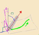
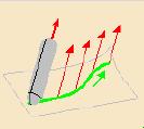
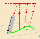
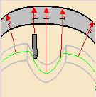
15 About Multi-Axis Sweeping Operation Multi-Axis Sweeping Operation: It is a milling operation in which the tool path is executed in parallel planes respecting user-defined geometric limitations and machining strategy parameters. In Multi-Axis Sweeping, the View Direction and Starting Direction define the guiding plane. Machining is done in planes parallel to the guiding plane. CAUTION: View Direction Definition: The view direction is very important because, it will decide which area is reachable regarding this view. Regarding the selected area and the view direction, CATIA will take care of the computed contour outline. Example: On a Sphere With a sphere: using Z axis as view direction (See Compass), the only reachable area is the green area concretized by tool trajectories here. The tool axis will be computed regarding the tool axis mode setting (interpolation, lead & tilt, etc), but never you will be able to reach the bottom side of the sphere. We will use the starting direction as well to compute the guiding plane. 15

16 How to Create a Multi-Axis Sweeping Operation 1 Click Multi-Axis Sweeping Operation icon The new Operation is created after the current one. The Operation dialog box displays to define its parameters 3 Define the Operation geometry and parameters in the dialog box 4 Replay the Tool Path 3 5 Confirm Operation creation The Operation is created in the PPR tree with a default tool. This capability can be removed by customizing the NC Manufacturing options
17 Multi-Axis Sweeping Operation: General Process 1 Type the Name of the Operation. (optional because a default name is given by the system Type_Of_Operation.X ) 2 Type a line of comment (optional) Define operation parameters using the 5 tab pages Strategy tab page Geometry tab page Tool tab page Feeds & Speeds tab page Macros tab page Before replaying or creating the operation, Preview checks that all parameters are coherent Replay and/or Simulate the operation tool path Click OK to create the operation
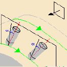
18 Strategy Definition (1/16) With these arrows, you can define the View Direction, the Start Direction, and optionally the Tool Axis Machining Tab page Radial Tab page Tool Axis Tab page 18


19 Strategy Definition (2/16) Machining Tab: Machining tolerance: Value of the maximum allowable distance between theoretical tool path and the tool path computed Max discretization step: Maximum length between two consecutive computed points Max discretization angle: Tolerate value of the tool Axis Angle variation between two consecutive computed points Min Path Length: All computed paths below this value will be removed 19
 Radial Tab: A.")


20 Strategy Definition (3/16) Radial Tab: A. Scallop Height value B. Distance on part A C. Distance on plane B OR C D D. Number of paths Define the Stepover side: Left or right 20
21 Strategy Definition (4/16) Tool Axis tab Lead and Tilt Fixed axis Thru a point Normal to line 4-Axis lead/lag Optimized lead Thru a guide Normal to drive surface 21

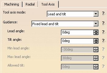
22 Strategy Definition (5/16) Lead and tilt: The tool axis is guided in Lead and Tilt mode. Lead and tilt means you can set two different angles. Lead => User-defined incline of the tool axis in a plane defined by the direction of motion and the normal to the part surface. The tool axis incline is with respect to the part surface normal. Tilt => User-defined incline of the tool axis in a plane normal to the direction of motion. The tool axis incline is with respect to the part surface normal. These angles are computed for each considered point regarding the normal vector of the surface. There are 3 Guidance modes for Lead and Tilt strategy: Regarding the mode you choose, you leave some freedom to the tool axis during the machining operation. 22

 or with the full tool body (for all other tool types).")


23 Strategy Definition (6/16) Fixed lead and tilt: Set the fixed Lead Angle Set the fixed Tilt Angle Variable Lead and Fixed Tilt: The purpose of variable Lead Mode is to avoid collisions between the machining part and tool rear side (in case of toroidal tool) or with the full tool body (for all other tool types). In Variable lead and fixed tilt mode, you may set a Max lead angle value and a Min lead angle value regarding the normal to the surface at the computed point. So you limit all big angle variation of the tool axis between two consecutive points A. Set the Reference Lead Angle B. Set the fixed Tilt Angle C. Set the Min Lead Angle D. Set the Max Lead Angle A C B D 23


24 Strategy Definition (7/16) Fixed lead and variable tilt: In Fixed lead and variable tilt mode, you canset a reference tilt angle value regarding the normal to the surface at the computed point and an allowed tilt variation. You set a fixed Lead Angle. A. Set the fixed Lead Angle B. Set the reference Tilt Angle A B C. Set the allowed tilt variation around its basic reference angle value C 24
25 Strategy Definition (8/16) In general, you must choose: A filleted-end tool for Variable lead and fixed tilt tool axis guidance. A ball-end tool for Fixed lead and variable tilt tool axis guidance Filleted-end tool Ball-end tool 25


26 Strategy Definition (9/16) Fixed axis: You can define the tool axis orientation by clicking the tool axis arrow (A) in the strategy tab page. The tool axis will keep constant orientation during the machining operation. Set the value by selecting the tool axis Axis Selection: This type of selection is available for all other operations Click one of the red tool axes in the sensitive icon, then specify the tool axis orientation at the start of machining. You can do this by selecting a surface. In this case the surface normal is used. 26
 Fixed axis:")


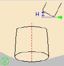
27 Strategy Definition (10/16) Fixed axis: Different available choices for tool axis orientation: By Components (coordinates) or by Angles 27


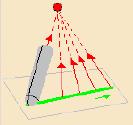
28 Strategy Definition (11/16) Thru a point: The tool axis keeps a constant direction toward the selected point during the whole Machining operation. Set the Point by selecting the point symbol 28

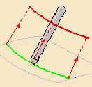
29 Strategy Definition (12/16) Normal to line: The tool axis remains perpendicular anytime during machining to the selected axis defined by the red Line symbol. Set the Line by selecting the red line symbol The tool axis is normal to the selected Line, and intersect it. It s a Normal and Through a Line. (Example: to be used for 4 Axis machine, selecting the C axis as table center axis) 29


30 Strategy Definition (13/16) 4-Axis lead/lag: You need to define a plane. The tool axis is constrained regarding the normal of this selected plane. A. Set the Plane by selecting the plane symbol B. Set a lead angle value A A B 30


31 Strategy Definition (14/16) Optimized lead: The tool Axis is guided in Optimized Lead mode. In this mode the maximum material removal is obtained when the tool curvature along the trajectory matches the part curvature. Min heel distance Set the Min and Max lead angle CAUTION: The Optimized Lead Mode is currently used with Torus Tool, so it is mandatory to set the min lead angle to a positive value in order to avoid machining with the flat area of the tool Set the Min heel distance 31


32 Strategy Definition (15/16) Thru a guide: You can control the tool orientation using a continuous geometrical curve (guide). An open guide can be extrapolated at its extremities. Click to select guide curve Mode: It defines the position of the tool on the guide. Normal to the path: At a given contact point, the intersection of the plane normal to the path with the guide gives the tilt angle of tool. If several intersections are found, then the nearest intersection is taken into account. Nearest position: The tool is orientated by the point that gives the shortest distance between the guide and the contact point. Nearest position along view direction: The guide is projected on a plane normal to the view direction. The tool is oriented by the point that gives the shortest distance between the projected guide and the current contact point. Offset on guide: Offset is computed on a plane defined by the tangent of the guide and the view direction or reference axis. Lead angle: Specifies an angle in the forward direction between default tool axis and actual tool axis. Extrapolates extremities of an open guide Depending on the Lead angle, the tool axis will not remain on the tilting guide. 32


33 Strategy Definition (16/16) Normal to drive surface: The tool axis remains normal to the auxiliary drive surface that you select. Recommend you to use a smooth surface. Drive surface Normal to drive surface Part surface Following points are considered for tool axis computation: Find the nearest point of the contact point on the auxiliary drive surface Compute the normal of this point on the drive surface Apply this normal direction on the tool axis, and rotate the tool axis in the plane (Tool axis, Tangent to the path) if a lead angle is given. 33
 Offset on limiting contour")
34 Geometry Definition (1/2) Offset on part Offset on check Part body element to machine Area to avoid Limiting curve Check element Side to machine: Inside or Outside the limiting curve Collision Checking (if active or not, Accuracy, Allowed gouging) Offset on limiting contour 34


35 Geometry Definition (2/2) Covering Mode Optional within Collision Checking: Collision Checking Active on check elements Without Covering mode Covering Mode active: Air cuts due to collision with check can be optimized using the covering mode. This new option is available with MULTI-AXIS CONTOUR DRIVEN and ISOPARAMETRIC MACHINING as well. With Covering mode 35

36 Tool Definition (1/2) Selection of Tool or Tool Assembly plays a vital role in performing the operation. You can select the tools from the catalog or you can define the tools as per your requirement. 1 Select the tool type available for the current operation 2 Type the name of the Tool. 3 4 Type a line of comment (optional) Specify a tool number that does not already exist Use the 2D Viewer to modify the parameters of the tool. The 2D Viewer is updated with the new values Click More to expand the dialog box to access tool s parameters such as Geometry, Technology and compensation Select the icons to access the Search Tool dialog box to query a tool in a Catalog 5 For the following capabilities: Create a new tool Select an already existing tool from the current document Select another tool in a catalog by means of a query 36

37 Tool Definition (2/2) You can use following tools for Multi-Axis Sweeping operation: Face Mill, End Mill, Conical Mill, T-Slotter, Barrel Mill Body diameter Vertical distance Overall length Barrel radius Cutting length Corner radius Radial distance Entry diameter Barrel Mill supports Lead and tilt, Fixed axis, Thru a point and Normal to line tool axis modes 37

38 Speeds and Feedrates Definition Speed is number of revolutions of the cutting tool or workpiece per unit time. Feedrate is the distance traveled by the cutting tool or workpiece in unit time and A Define the Feedrate values for Approach Feedrate: This feedrate is used by default during approaches motion Machining Feedrate: This feedrate is used during Machining motion Retract Feedrate: This feedrate is used by default during retract motion Transition Feedrate: This feedrate is used during Transition motion A B Define the Spindle Speed value according to the unit Linear (m/mn) or Angular (turn/mn) This Spindle Output is optional, you can remove this information from the output by deactivating the check box Spindle Output C B C Rough or Finish quality of the operation and the tool data are taken into account for computing the feeds and speeds from the current tool catalog. 38


39 Macros Definition (1/7) A B Specify which NC Macros you want to use among: Approach Macro Retract Macro Return in a Level Linking Clearance Specify a radius value to cornerize the clearance motion. Check the Smooth tool axis moves to smoothen the transition path. A Corner radius Clearance Corner radius C B C Approach motion Specify for each selected NC Macro the type of motion and the parameters like Feedrates, Angles, etc Retract motion 39


40 Macros Definition (2/7) You will learn how to create a NC Macro for a Multi-Axis Sweeping Operation and for axial operations. For all operations, macro parameters are accessible using the highlighted tab page 40


41 Macros Definition (3/7) Pre-defined macros Depending on the type of macro you have selected, different types of pre-defined macros are available: Tangent, normal Axial For Approach For Retract Circular Vertical Helix for approach Normal motion 41


42 Macros Definition (4/7) Macros Tool Box: Tangent Axial Horizontal You can create an infinite number of different macros by selecting each of this basic trajectory in various order or use contextual menu on a selected move to add a new one, remove or edit it to tune some parameters. 42


43 Macros Definition (5/7) Create your own macro: Insert a PP word on a point of the macro. Crosses localize the possible points to insert the PP word. To insert a PP word, you can also press right mouse button on the cross and select «PP word list» PP Table access capability: Possibility to select Major/Minor words and pre-defined syntaxes Apply this Approach or Retract motion to all Return and Linking macros in the operation (only available on Approach macro and Retract macro) 43


44 Macros Definition (6/7) Modify parameters on your macro: To locally modify a feedrate in the macro, right-click the element and select «feedrate» to choose which feedrate to associate between Machining, Approach, Retract, Rapid, Local or Finishing Depending on the feedrate selected, the element takes a different color: Yellow : Approach White : Local Green : Machining Blue : Retract Red : Rapid To modify geometrical parameters of a macro, double-click it. 44

45 Macros Definition (7/7) Return in a level, Linking and Clearance Macro: Return in a level and Linking macros are divided in two motions: Approach and Retract The Clearance Macro: Between those two motions, the system computes a transition tool path to avoid Collisions, Islands or Fixtures. If you want this transition tool path to be a simple return to a safety plan, activate Clearance Macro. You can cornerize clearance via as shown below. When Smooth tool axis moves is checked, if the approach and the retract axes are different, additional points are added on the rapid motion to smoothen the transition path. Corner radius Clearance Corner radius Approach motion Retract motion 45
46 Master Exercise: Fender Step 2: Create Multi-Axis Sweeping Operations 35 min In this step you will learn how to perform a 5-Axis Sweeping Operation. You will see a Multi-Axis Sweeping Operation with: Fixed lead and tilt Tool Axis Guidance, Fixed lead and variable tilt Tool Axis Guidance, Fixed Tool axis mode, Thru a Point Tool axis mode, Normal to line Tool axis mode, 4-axis lead/lag Tool axis mode, Optimized Lead Tool axis mode. 46

47 Multi-Axis Contour Driven Operation You will become familiar with creation of a Multi-Axis Contour Driven Operation. 47
48 About Multi-Axis Contour Driven Operation Concept: It is a milling operation in which the tool is driven along a contour while respecting user-defined geometric limitations and machining strategy parameters. Three machining modes are Parallel Contour, Between Contours and Spine Contour. A number of tool axis guidance modes are available. Same as Multi-Axis sweeping 48

49 How to Create a Multi-Axis Contour Driven Operation 1 Click Multi-Axis Contour Driven Operation icon The new Operation is created after the current one. The Operation dialog box displays to define its parameters 3 Define the Operation geometry and parameters in the dialog box 4 Replay the Tool Path 3 5 Confirm Operation creation The Operation is created in the PPR tree with a default tool. This capability can be removed by customizing the NC Manufacturing options


50 Strategy Definition (1/4) A milling operation in which the tool is driven along a contour while respecting userdefined geometric limitations and machining strategy parameters. Three machining modes are Between Contours, Parallel contour and Spine Contour. Tool axis guidance modes are available same as Multi-Axis Sweeping i.e Lead and Tilt, Thru a point, Normal to line, etc Tool Axis mode Choice between three guiding Strategies One additional Strategy tab activated when using a reference Parallel contour 50


51 Strategy Definition (2/4) Between Contours: Guide 1 Guide 2 The Strategy sub-tab is deactivated in Between Contours mode In Between contour mode we have the ability to specify different offset values and Tool Position on the two guides to avoid creation of additional geometry You can apply the same offset on stops which is set on guides 51

52 Strategy Definition (3/4) Parallel Contour: The strategy allows you to machine paths TO/FROM (new in R12) the reference contour from the far limit defined by the Maximum width to machine parameter. Guide 1 The Strategy sub-tab is activated for Parallel contour mode Width to machine starting from right side of guide contour(or going to the contour guide) depending on direction choice 52

53 Strategy Definition (4/4) Spine Contour: Guide 1 The Strategy sub-tab is deactivated for Spine contour mode 53
54 Master Exercise: Fender Step 3: Create a Multi-Axis Contour Driven Operation 15 min In this step you will learn how to perform a 5-Axis Contour Driven Operation. You will see a Multi-Axis Contour Driven Operation with: Case1 Between Contours guiding strategy, Case2 With Parallel Contour guiding strategy, Case3 With Spine Contour guiding strategy. 54
55 Multi-Axis Curve Machining Operation You will learn how to create a Multi-Axis Curve Machining Operation. 55
56 About Multi-Axis Curve Machining Operation Concept: This is a milling operation in which the tool's side, tip or contact point is driven along a curve while respecting user-defined geometric limitations and machining strategy parameters. A number of tool axis guidance modes are available. Same as Multi-Axis Sweeping. 56


57 How to Create a Multi-Axis Curve Machining Operation 1 Click Multi-Axis Curve Machining Operation icon 2 2 The new Operation is created after the current one. The Operation dialog box appears to edit it 1 3 Define the Operation geometry and parameters in the dialog box 4 Replay the Tool Path 3 5 Confirm Operation creation The Operation is created in the PPR tree with a default tool. This capability can be removed by customizing the NC Manufacturing options


58 Strategy Definition (1/8) A milling operation in which the tool is driven along a contour while respecting userdefined geometric limitations and machining strategy parameters. Three machining modes are Contact, Between 2 curves and between curve and part. Multi-Axis Curve Machining: The curve can be machined by the tool's contact point, tip or side. The tool axis guidance modes are available in the strategy Tab. Guidance Modes 58


59 Strategy Definition (2/8) Guidance modes available in Multi Axis Curve Machining are: Interpolation: B A A. Choice of Tool Axis at Starting Point B. Choice of Tool Axis at Ending Point C. Tool axis orientation C A B C orient the tool axis perpendicular to the screen view. Additional Interpolation axes 59
 interpolation axes: Create: It allows to create a new interpolation axis.")


60 Strategy Definition (3/8) Interpolation: You can add any number of interpolation axes to control the interpolation. Adding / modifying (editing) interpolation axes: Create: It allows to create a new interpolation axis. Select the position of the interpolation axis in 3D viewer, and then the axis definition dialog box will be displayed. After adding all the axes, the axes displayed in 3D viewer and the list of axes appears in the Interpolation Axes dialog box. Clicking red arrow allows you to add, edit or remove the axes through dialog box. Remove: It allows you to remove the interpolation vector selected in the dialog box. Edit: It allows you to modify the interpolation axis selected in the dialog box. The Check Interferences option is available when you select the Display tool check box and the operation parameters are coherent. Axis definition 60


61 Strategy Definition (4/8) Tangent Axis for Between 2 curves and Between curve and part ONLY In Tangent Axis mode, the tool axis is chosen to follow the ruling directions of the Drive Surface which are supposed to be developable or planer (if one Drive Surface does not respect these conditions, a message is displayed at the end of the computation). This is the only tool axis providing an linear contact between the cutter and the Drive Surface. Maximum material removal is obtained when ruling direction on drive surface matches the ruling direction on tool. Select Drive Surface Mode options: 61
. This is done even if the surface is planar, or it is not developable.")
62 Strategy Definition (5/8) Tangent Axis MODE: We have two possible sub-strategies of the tangent axis A) The drive surfaces are ruled (even if not developable), ruling direction are the isoparametric line or the surfaces, so the tool axis is mapped to the iso-line (the one which is the less parallel to the drive curve). This is done even if the surface is planar, or it is not developable. B) The isoparametric lines of the drive surfaces are not compatible with the NC Machine travel limits or may lead to collision with the machine head or may lead to loops in the tool path. In these cases, the user wants the tool axis to be tangent to the drive surface, and normal to the drive curve. In both cases, because the tool axis is not always the ruling direction of the developable surface, some under or over cuts may occur, and the user expect to have an immediate feedback of these deviations. Three sub-strategies are added to the tangent axis: 1) Along ruling direction Message displays when facing non- ruled surfaces 2) Along isoparametric lines 3) Normal to drive curve For the cases 2 and 3, at the end of computation the maximum and minimum deviation to the drive surfaces is displayed. 62


63 Strategy Definition (6/8) Fanning Distance: The tangent axis mode is used when you machine ruled and planer surfaces. On a planar surface before or after a ruled one the tool may change its inclination more or less smoothly. The fanning distance is the allowed transition distance during which the tool is changing its axis position. Fanning Distance 63

, the tool axis is computed by")

64 Strategy Definition (7/8) Tangent Axis MODE Along isoparametric lines: On all computed tool position (driven by a point on the drive curve), the tool axis is computed by selecting the closest Iso line direction from the drive surface regarding the reference tool axis. 64
, the point")


65 Strategy Definition (8/8) Tangent Axis MODE Normal to drive Curve: On all computed tool position (driven by a point on the drive curve), the point on the drive curve is projected on the drive surfaces, on the projected point we evaluate the Normal vector to the surface, N Then we define the un-oriented direction of the tool axis Ta=T^N where T is the tangent vector of the drive surface. Example of maximum and minimum deviations displayed 65
66 Geometry Definition (1/11) Curve Machining Mode Contact: Guide Curve Guide Curve Support surface Resulting Tool Paths 66

67 Geometry Definition (2/11) Contact: Limit Point Guide Curve Limit Point Offset on Limit Option on Limits: In, Out or On Offset on Limit Value 67

68 Geometry Definition (3/11) Curve Machining Mode Between 2 curves: Guides Choice between computation points mode: Side or Tip 68
69 Geometry Definition (4/11) Between 2 curves Choice of one curve: A. Axial Offset Value B. Offset Value on Contour A A B B 69

70 Geometry Definition (5/11) Between 2 curves Choice of two curves: A A. Guide B. Auxiliary Guide Curve C. Side Mode: Tangent to Guide A C B B C 70

71 Geometry Definition (6/11) Between 2 curves Choice of two curves: A. Guide B. Auxiliary Guide Curve C. Tip Mode A A C B B Tip Mode: Tip on Guide C 71


72 Geometry Definition (7/11) Between curve and part: You need to select one curve and one Surface. B A A. Guide Curve B. Interpolation vectors defined in Strategy Tab C. Option Side = tangent to guide Curve D. Surface to machine A C D C D 72
73 Geometry Definition (8/11) Between curve and part: You can select a plane as part to machine in Between curve and part and Contact modes. A A. Guide Curve B. Plane as part A B B The machining is done as a planar surface. This equivalent planar surface is delimited by a bounding box, which is twice the bounding box of the projection of the guiding curve normal to the plane. 73


74 Geometry Definition (9/11) Between Curve and Part: A B A. Guide Curve B. Limit Point C. Option Tip = ON guide Curve A C B C 74

75 Geometry Definition (10/11) Between Curve and Part: Use of Tangent Axis Guidance Mode in Strategy Tab A A. Guide Curve B. Part to Machine C. Drive Surface A C B C B 75


76 Geometry Definition (11/11) Between Curve and Part: Use of Fanning distance Variation Infinite Fanning Distance Small Fanning Distance 76
77 Macros Definition There are 7 different main types of macros available: Approach Retract Return in a level Return between levels Linking Clearance Return to finish passes 77
78 Master Exercise: Fender Step 4: Create a Multi-Axis Curve Machining Operation 15 min In this step you will learn how to perform a Multi-Axis Curve Machining Operation. You will see how to create this operation using: Between 2 Curves mode, Contact mode, Between curve and part mode 78
79 Multi-Axis Isoparametric Machining Operation You will learn how to create of a Multi-Axis Isoparametric Machining Operation. 79
80 About Multi-Axis Isoparametric Machining Operation Concept Isoparametric machining is an operation which allows you to select strips of faces and machine along their isoparametrics. A number of tool axis guidance modes are available same as Multi-Axis Sweeping. The most advisable guidance mode is INTERPOLATION. You may control in some critical point the Tool Axis orientation 80

81 How to Create a Multi-Axis Isoparametric Operation 1 Click Isoparametric Machining Operation icon The new Operation is created after the current one. The Operation dialog box appears to edit it 3 Define the Operation geometry and parameters in the dialog box 4 Replay the Tool Path 3 5 Confirm Operation creation The Operation is created in the PPR tree with a default tool. This capability can be removed by customizing the NC Manufacturing options

82 Strategy Definition (1/4) This is a milling operation in which the tool paths are executed on strip surfaces respecting user-defined geometric limitations and machining strategy parameters. Multi-Axis Isoparametric Machining: A number of tool axis guidance modes are available in the strategy Tab. In order to control the axis position anytime, it is advisable to use the Interpolation Option Guidance Modes 82
83 Strategy Definition (2/4) Interpolation Guidance mode available in Multi-Axis Isoparametric Machining. Interpolation: Choice of Tool Axis at Beginning Point Choice of Tool Axis at Intermediate Point 83


84 Strategy Definition (3/4) Interpolation: You can add anywhere on the machining area some Intermediate points with predefined tool vector axis. They will be taken into account during tool path computation. Possibility to remove in contextual menu all additional Points Create, Remove or Edit the interpolation axes When the Angles option is selected, the drop down list proposes by default an item specific to interpolation axes: Lead (Angle1) & Tilt (Angle 2). 84

85 Strategy Definition (4/4) Interpolation: Radial Tab Skip Path: It is possible to skip the first, last or first-and-last paths Extension: Start and End It is possible to start the computation using an extrapolation value for the Start or the End of the operation. Tool path extension in Isoparametric Machining: You can now extend or reduce the width of the tool path before the first path and after the last path. You can extend the width when you want machining to continue beyond the boundary of the selected part surface. You can reduce it to keep a given distance between check surfaces and the first & last paths. This avoids creating virtual part surface geometry and gives better surface finish at ends of the part surface and reduced risk of interference with check surfaces. Set value for extrapolation 85
 must be defined for each face and belt of faces.")
86 Geometry Definition You may select adjacent or non- adjacent faces. The faces will be machined in a single Isoparametric Machining operation. In this case corners must be selected for each face and belt of face. Also an orientation (side to mill) must be defined for each face and belt of faces. Advices: Create an healing or join ( with federate option) before selecting machining surfaces. This will improve the continuity detection between consecutive boundaries Main Isoparameter directions Couple Points (1,2) Choice of points to drive the first tool path direction Couple points Parts to machine Covering Mode availability 86


87 Macros Definition There are different types of macros available: Approach Retract Clearance Linking Return in a level Approach macro Retract macro Use of linking option between two groups of machined faces 87
88 Multi-Axis Drilling Operation You will become familiar with creation of a Multi-Axis Drilling Machining Operation. 88
89 About Multi-Axis Drilling Operation Concept: The drilling (or axial machining) operations described in this section are intended to cover the hole making activities in your NC manufacturing program. In particular, the commands and capabilities included in the Geometry tab page of the Axial Machining Operation dialog box allow support of multi-axis as well as fixed axis drilling. 89

90 How to Create a Multi-Axis Drilling Operation 1 Click Multi-Axis Drilling Operation icon The new Operation is created after the current one. The Operation dialog box appears to edit it 3 Define the Operation geometry and parameters in the dialog box 4 Replay the Tool Path 3 5 Confirm Operation creation The Operation is created in the PPR tree with a default tool. This capability can be removed by customizing the NC Manufacturing options


91 Strategy Definition You can choose Depth, plunge modes. You can edit the cycle to customize the syntax Setting parameters for drilling cycle Breakthrough (B) available if option Extension is Trough in Geometry tab 91

92 Geometry Definition Drill parameters setting: Choice of Machining Pattern Multi-Axis Drill => Normal to Part Surface direction Points to drill More Options: Machine different depths Machine Blind/Through Inverse Pattern ordering,etc 92

93 Macros Definition There are 5 different types of macros available: Approach Retract Clearance Linking Retract Linking Approach Macro Adding distance along a line Motion in Approach 93
94 Multi-Axis Tube Machining Operation You will become familiar with creation of a Multi-Axis Tube Machining Operation. 94
95 About Multi-Axis Tube Machining Operation Concept: This type of Multi-Axis Machining is suitable for parts presenting an obvious central axis While respecting user-defined geometric limitations and machining strategy parameters. A number of tool axis guidance modes are available. Same as Multi-Axis sweeping 95


96 How to Create a Multi-Axis Tube Machining Operation 1 Click Multi-Axis Tube Machining Operation icon The new Operation is created after the current one. The Operation dialog box appears to edit it 3 Define the Operation geometry and parameters in the dialog box 4 Replay the Tool Path 3 5 Confirm Operation creation The Operation is created in the PPR tree with a default tool. This capability can be removed by customizing the NC Manufacturing options

97 Strategy Definition (1/8) This is a milling operation in which the tool is driven by a contour respecting userdefined geometric limitations. Three machining modes available are Around guide, Along guide or Helical. Driving tool points: Tool tip: You can use this option only with ball end tool for good quality tool path. Contact on part: The time required to create the tool path will be more using this option. The tool axis guidance modes available are: Choice between 3 guiding Strategies Driving tool points: Tool tip, Contact on part Tool Axis modes Tool path styles Collision checking is must while using Contact on part as driving tool points. 97


98 Strategy Definition (2/8) Around guide: Around Guide allows you to select between two different tool path styles - Zig zag or One Way. Guide Limit1 and Limit 2 98


99 Strategy Definition (3/8) Along guide: Along Guide allows you to select tool path styles among - Zig zag, One Way or Back and forth 99


100 Strategy Definition (4/8) Helical: Tube Cavity Tube and cavity Zone: Available when you select Tool tip as Driving tool points. Tube: To machine the tube. Cavity: To machine the bottom of the tube. Tube and cavity: To machine the tube and its bottom in a single action. Elevation angle: It is the end angle of the cavity. You can specify the value when Zone is set to Cavity. 100
")


101 Strategy Definition (5/8) Axial Stepover: There are 4 different ways to define the step over Scallop Height Distance on Part Distance on Guide Number of paths 101


102 Strategy Definition (6/8) Tool Axis Mode: Fixed axis: The tool axis remains constant for the operation. There are no associated parameters. Thru a Point: The tool axis passes through a specified point. Along guide: The tool axis makes a constant Tilt angle with the guide. You must define the Guide angle By default, the Allows variable tilt check box is not selected. If you select it, the axis is automatically adjusted around its initial position to avoid collision with part or checks. By default, the In opposite to machining direction check box is selected. This check box enables you to decide whether the tool is in machining direction or in the opposite direction. 102


103 Strategy Definition (7/8) Tool Axis Mode: Lead and tilt: In this mode the tool axis is normal to the part surface with respect to a given lead angle in the forward tool motion and with respect to a given tilt angle in the perpendicular direction to this forward motion. The associated parameters depend on the Guidance selected. This Lead and tilt mode is same as for Multi-Axis Sweeping operation. 4- Axis Tilt: The tool axis is normal to the part surface with respect to a given tilt angle and is constrained to a specified plane. This 4- Axis Tilt mode is same as for Multi-Axis Curve machining. You must type the Tilt angle and Lead angle 103


104 Strategy Definition (8/8) Guide mode selection: The guide may be defined directly as an Axis. For this you need to Right-click the guide and another scrolled menu will appear. Guiding Strategy Selection The machining direction is then displayed at one end of the guide. Need to select a direction and a point for start condition Click the arrow to invert the machining direction if necessary. 104
105 Tools Definition Recommended tool families for Multi-Axis Tube Machining are: Face mill End mill (ball- ended or not) Conical mill (ball- ended or not) T- slotter CAUTION: Areas that cannot be reached by the beams issued from the guide are not machined. 105


106 Macros Definition (1/2) Add normal motion : It adds a linear motion normal to the part surface. You can use it in the linking macros to avoid the collision. Add circular motion : It adds a circular motion in a plane. Normal to last tool axis: Normal to part surface: It is useful with Along guide strategy in return in a level macros. 106


107 Macros Definition (2/2) Enable 5-Axis Simultaneous Motion: Using this macro you can generate a five-axis simultaneous motion on the next combined motion. The macro rotates the tool in macro paths and thus helps in minimizing machine jolts by generating a 5-axis simultaneous motion on the next combined motion. Direction defined in new macro motion Tangent motion Start tool axis of machining path You have to define a direction. 107
108 Multi-Axis Spiral Milling Operation In this lesson, you will learn how to create a Multi-Axis Spiral Milling Operation by defining different strategies. 108
109 About Multi-Axis Spiral Milling Operation Concept: It is a milling operation used to machine pockets or to engrave complex surfaces in order to get better surface quality, too life and optimization of tool path. The tool is driven along a guide while respecting user-defined geometric limitations and machining strategy parameters. Three tool path styles: Helical, Back and forth and Contour only. The tool axis guidance modes available are Fixed or Normal to part. Guide face 109

110 How to Create a Multi-Axis Spiral Milling Operation 1 Click Multi-Axis Spiral Milling Operation icon The new Operation is created after the current one. The Operation dialog box appears to edit it 3 Define the Operation geometry and parameters in the dialog box 4 Replay the Tool Path 3 5 Confirm Operation creation The Operation is created in the PPR tree with a default tool. This capability can be removed by customizing the NC Manufacturing options


111 Strategy Definition (1/3) Machining tab: Machining tolerance: It is the value of the maximum allowable distance between theoretical tool path and the computed tool path Direction of cut The cutting mode which can be Climb or Conventional Climb Conventional Helical movement Inward: The tool path will begin at the outer limit of the area to machine and work inwards. Max discretization angle: It is the maximum angular change of tool axis between tool positions. Outward: The tool path will begin at the middle of the area to machine and work outwards. Always stay on bottom: It forces the tool to remain in contact with the pocket bottom when moving from one domain to another. 111


112 Strategy Definition (2/3) Radial tab: Distance between paths: It allows you to define the maximum distance between successive passes in the tool path. Contouring pass: It adds a contouring pass at the end of the back and forth path. Contouring ratio: It adjusts the position of the contouring pass to optimize scallop removal (% of tool diameter). Axial Parameters: Maximum cut depth Number of levels 112


113 Strategy Definition (3/3) Tool Axis tab: Fixed axis: The axis is fixed. Normal to part: The tool is normal to the bottom of the part with an angular tolerance. HSM tab: Corner sub-tab Corner radius: You can define the corner radius to round the ends of passes. Limit angle: It is the minimum angle the tool path must form to allow the rounding of the corners. Extra segment overlap: It is an overlap for the extra segments that are generated for cornering Transition sub-tab Transition radius: The radius at the extremities of a transition path. Transition angle: It is the angle of the transition path that ensures a smooth movement from one path to another Transition length: It is the minimum length of the straight segment of the transition path. 113

114 Geometry Definition You need to select Part and Guide faces. You can define islands using the guide faces. Possible offsets on Part, check or Guide faces Selection of check elements Selection of the Soft guide contour that closes the guide faces if the pocket is open. Collision Checking: Collision checking can be performed on the cutting part of tool or on the cutting part of the tool and its tool assembly (if check box is selected). To save computation time, you must select tool assembly only if the geometry to be checked can interfere with the upper part of the cutter. 114
115 Exercises You will perform following exercises to reinforce the knowledge learnt in the course. Exercise 1: Hood Exercise 2: Pocket Exercise 3: Isoparametric and Drill Exercise 4: Multi-Axis Curve Machining Exercise 5: Tube Machining Exercise 6: Multi-Axis Spiral Machining 115
116 Exercise 1: Hood Exercise Presentation 40 min In this exercise, you will practice 5-Axis Machining on a Hood. You will have the chance to try out various tools and various modes to create 5-axis tool paths. You will again learn how to prepare a geometry, define macros and start a machining process. 116
117 Exercise 2: Pocket Exercise Presentation 15 min In this exercise, you will see how to create a Multi-Axis Operation with: Between curve and part Curve Machining Mode Tangent Axis Mode Strategy 117
118 Exercise 3: Isoparametric and Drill Exercise Presentation 15 min In this exercise, you will see how to create a Multi-Axis Isoparametric Operations and Drilling Operations: Isoparametric using Interpolation Mode Axis Multi-Axis Drilling Operations 118
119 Exercise 4: Multi-Axis Curve Machining Exercise Presentation 15 min In this exercise, you will see the difference between the Submod available in Multi Axis Curve Machining With Tangent Axis Mode: Along isoparametric Line Normal to drive curve 119
120 Exercise 5: Tube Machining Exercise Presentation 40 min In this exercise, you will see how to create fundamental Multi-Axis Tube Machining Operations: Use Along Guide Strategy Use of different Tool Axis Mode Along Guide with tilt Angle 32deg for Ouside process Thru Point strategy for Inside wall process 120
121 Exercise 6: Multi-Axis Spiral Machining Exercise Presentation 10 min In this exercise, you will learn how to create a Multi-Axis Spiral Machining Operation. 121
CATIA V5 Training Foils
 CATIA V5 Training Foils Prismatic Machining Version 5 Release 19 January 2009 EDU_CAT_EN_PMG_FF_V5R19 1 About this course Objectives of the course Upon completion of this course you will be able to: -
Multi-Pockets Machining
 CATIA V5 Training Foils Multi-Pockets Machining Version 5 Release 19 January 2009 EDU_CAT_EN_MPG_FF_V5R19 1 About this course Objectives of the course Upon completion of this course you will be able to
Advanced Part Machining
 CATIA V5 Training Exercises Advanced Part Machining Version 5 Release 19 January 2009 EDU_CAT_EN_AMG_FX_V5R19 1 Table of Contents (1/2) Exercise Presentation 4 CATIA Settings 5 Multi-Axis Flank Contouring:
Prismatic Machining Overview What's New Getting Started User Tasks
 Prismatic Machining Overview Conventions What's New Getting Started Enter the Workbench Create a Pocketing Operation Replay the Toolpath Create a Profile Contouring Operation Create a Drilling Operation
VERO UK TRAINING MATERIAL. 2D CAM Training
 VERO UK TRAINING MATERIAL 2D CAM Training Vcamtech Co., Ltd 1 INTRODUCTION During this exercise, it is assumed that the user has a basic knowledge of the VISI-Series software. OBJECTIVE This tutorial has
Lesson 3: Surface Creation
 Lesson 3: Surface Creation In this lesson, you will learn how to create surfaces from wireframes. Lesson Contents: Case Study: Surface Creation Design Intent Stages in the Process Choice of Surface Sweeping
Lesson 4: Surface Re-limitation and Connection
 Lesson 4: Surface Re-limitation and Connection In this lesson you will learn how to limit the surfaces and form connection between the surfaces. Lesson contents: Case Study: Surface Re-limitation and Connection
4 & 5 Axis Mill Training Tutorials. To order more books: Call or Visit or Contact your Mastercam Dealer
 4 & 5 Axis Mill Training Tutorials To order more books: Call 1-800-529-5517 or Visit www.inhousesolutions.com or Contact your Mastercam Dealer Mastercam X Training Tutorials 4 & 5 Axis Mill Applications
NC Manufacturing Verification
 NC Manufacturing Verification Page 1 Preface Using This Guide Where to Find More Information Conventions What's New? User Tasks Accessing NC Manufacturing Verification Comparing the Machined Stock Part
Create Complex Surfaces
 Create Complex Surfaces In this lesson, you will be introduced to the functionalities available in the Generative Surface Design workbench. Lesson content: Case Study: Surface Design Design Intent Stages
CATIA V5 Parametric Surface Modeling
 CATIA V5 Parametric Surface Modeling Version 5 Release 16 A- 1 Toolbars in A B A. Wireframe: Create 3D curves / lines/ points/ plane B. Surfaces: Create surfaces C. Operations: Join surfaces, Split & Trim
Mill Level 1 Training Tutorial
 To order more books: Call 1-800-529-5517 or Visit www.inhousesolutions.com or Contact your Mastercam dealer Mastercam X 5 Copyright: 1998-2010 In-House Solutions Inc. All rights reserved Software: Mastercam
NC Manufacturing Verification
 NC Manufacturing Verification Overview Conventions What's New? User Tasks Accessing NC Manufacturing Verification Comparing the Machined Stock Part and the Design Part Pick Point Analysis in Video Mode
Brief Introduction to MasterCAM X4
 Brief Introduction to MasterCAM X4 Fall 2013 Meung J Kim, Ph.D., Professor Department of Mechanical Engineering College of Engineering and Engineering Technology Northern Illinois University DeKalb, IL
SolidCAM Training Course: Turning & Mill-Turn
 SolidCAM Training Course: Turning & Mill-Turn imachining 2D & 3D 2.5D Milling HSS HSM Indexial Multi-Sided Simultaneous 5-Axis Turning & Mill-Turn Solid Probe SolidCAM + SolidWorks The Complete Integrated
MASTERCAM DYNAMIC MILLING TUTORIAL. June 2018
 MASTERCAM DYNAMIC MILLING TUTORIAL June 2018 MASTERCAM DYNAMIC MILLING TUTORIAL June 2018 2018 CNC Software, Inc. All rights reserved. Software: Mastercam 2019 Terms of Use Use of this document is subject
Training Guide CAM Basic 1 Getting Started with WorkNC
 Training Guide CAM Basic 1 Getting Started with WorkNC Table of Contents Table of Contents 1 Training Guide Objectives 1-1 2 Introduction 2-1 2.1 Part Geometry Preparation 2-1 2.2 Starting WorkNC 2-2
What s new in EZCAM Version 18
 CAD/CAM w w w. e z c a m. com What s new in EZCAM Version 18 MILL: New Curve Machining Wizard A new Curve Machining Wizard accessible from the Machining menu automates the machining of common part features
Lesson 2: Wireframe Creation
 Lesson 2: Wireframe Creation In this lesson you will learn how to create wireframes. Lesson Contents: Case Study: Wireframe Creation Design Intent Stages in the Process Reference Geometry Creation 3D Curve
CNC Programming Simplified. EZ-Turn / TurnMill Tutorial.
 CNC Programming Simplified EZ-Turn / TurnMill Tutorial www.ezcam.com Copyright Notice This manual describes software that contains published and unpublished works of authorship proprietary to EZCAM Solutions,
Copyright 2019 OPEN MIND Technologies AG
 Copyright 2019 OPEN MIND Technologies AG This document applies to hypermill and hypermill SHOP Viewer. It contains notes about recent changes that are not described in the manual. All rights reserved.
Mastercam X9 for SOLIDWORKS
 Chapter 21 CO2 Shell Car Mastercam X9 for SOLIDWORKS A. Enable Mastercam for SOLIDWORKS. Step 1. If necessary, turn on Mastercam for SOLIDWORKS, click the flyout of Options on the Standard toolbar and
What's New in BobCAD-CAM V29
 Introduction Release Date: August 31, 2016 The release of BobCAD-CAM V29 brings with it, the most powerful, versatile Lathe module in the history of the BobCAD-CAM software family. The Development team
What's New in CAMWorks 2016
 Contents (Click a link below or use the bookmarks on the left) About this Version (CAMWorks 2016 SP3)... 2 Supported Platforms 2 Resolved CPR s document 2 About this Version (CAMWorks 2016 SP2.2) 3 Supported
Aerospace Sheet Metal Design
 CATIA V5 Training Foils Aerospace Sheet Metal Design Version 5 Release 19 January 2009 EDU_CAT_EN_ASL_FI_V5R19 1 About this course Objectives of the course Upon completion of this course you will be able
TOOLPATHS TRAINING GUIDE. Sample. Distribution. not for MILL-LESSON-4-TOOLPATHS DRILL AND CONTOUR
 TOOLPATHS TRAINING GUIDE MILL-LESSON-4-TOOLPATHS DRILL AND CONTOUR Mill-Lesson-4 Objectives You will generate a toolpath to machine the part on a CNC vertical milling machine. This lesson covers the following
CATIA Surface Design
 CATIA V5 Training Exercises CATIA Surface Design Version 5 Release 19 September 2008 EDU_CAT_EN_GS1_FX_V5R19 Table of Contents (1/2) Creating Wireframe Geometry: Recap Exercises 4 Creating Wireframe Geometry:
Belt Buckle A. Create Rectangle. Step 1. If necessary start a new Mastercam file, click New
 Mastercam 2017 Chapter 35 Belt Buckle A. Create Rectangle. Step 1. If necessary start a new Mastercam file, click New (Ctrl-N) on the Quick Access Toolbar QAT. Step 2. On the Wireframe tab click Rectangle.
CATIA V5-6R2015 Product Enhancement Overview
 Click to edit Master title style CATIA V5-6R2015 Product Enhancement Overview John Montoya, PLM Technical Support March 2015 1 2010 Inceptra LLC. All rights reserved. Overview of Enhanced Products Overview
Mechanical Design V5R19 Update
 CATIA V5 Training Foils Mechanical Design V5R19 Update Version 5 Release 19 August 2008 EDU_CAT_EN_MD2_UF_V5R19 1 About this course Objectives of the course Upon completion of this course you will be able
Piping Design. Site Map Preface Getting Started Basic Tasks Advanced Tasks Customizing Workbench Description Index
 Piping Design Site Map Preface Getting Started Basic Tasks Advanced Tasks Customizing Workbench Description Index Dassault Systèmes 1994-2001. All rights reserved. Site Map Piping Design member member
Equipment Support Structures
 Equipment Support Structures Overview Conventions What's New? Getting Started Setting Up Your Session Creating a Simple Structural Frame Creating Non-uniform Columns Creating Plates with Openings Bracing
2D Toolpaths. The Best of Both Worlds. Contouring, Drilling, and Pocketing. Confidence at the Machine. Dependable Toolpath Verification
 for SolidWorks The Best of Both Worlds 2D Toolpaths Mastercam for SolidWorks combines the world s leading modeling software with the world s most widely-used CAM software so you can program parts directly
Polar coordinate interpolation function G12.1
 Polar coordinate interpolation function G12.1 On a Turning Center that is equipped with a rotary axis (C-axis), interpolation between the linear axis X and the rotary axis C is possible by use of the G12.1-function.
Part Design Features Recognition
 CATIA V5 Training Foils Part Design Features Recognition Version 5 Release 19 January 2009 EDU_CAT_EN_FR1_FI_V5R19 1 About this course Objectives of the course Upon completion of this course you will be
Additional Exercises. You will perform the following exercises to practice the concepts learnt in this course:
 Additional Exercises You will perform the following exercises to practice the concepts learnt in this course: Master Exercise : Mobile Phone Plastic Bottle Exercise 1 Master Exercise : Mobile Phone In
Aerospace Sheet Metal Design
 CATIA V5 Training Foils Aerospace Sheet Metal Design Version 5 Release 19 January 2009 EDU_CAT_EN_ASL_FF_V5R19 1 About this course Objectives of the course Upon completion of this course you will be able
Equipment Support Structures
 Page 1 Equipment Support Structures Preface Using This Guide Where to Find More Information Conventions What's New? Getting Started Setting Up Your Session Creating a Simple Structural Frame Creating Non-uniform
Mill Level 3. Capture Your Machining Knowledge
 Mill Level 3 Capture Your Machining Knowledge Mastercam's full associativity gives you the power to capture your knowledge and build on your experience. Once you program a part - any part - you can modify
What s new in EZ-CAM 2016 (version 23)
") What s new in EZ-CAM 2016 (version 23) MILL Pro 64-bit Edition is Ready: EZ-MILL Pro 2016 comes with a 64-bit edition which now makes it possible to import and create 3D toolpaths for very large and complicated
What s new in EZ-CAM 2016 (version 23) MILL Pro 64-bit Edition is Ready: EZ-MILL Pro 2016 comes with a 64-bit edition which now makes it possible to import and create 3D toolpaths for very large and complicated
CNC Programming Simplified. EZ-Turn Tutorial.
 CNC Programming Simplified EZ-Turn Tutorial www.ezcam.com Copyright Notice This manual describes software that contains published and unpublished works of authorship proprietary to EZCAM Solutions, Inc.
Realistic Shape Optimizer
 CATIA V5 Training Foils Realistic Shape Optimizer Version 5 Release 19 January 2009 EDU_CAT_EN_RSO_FI_V5R19 1 About this course Objectives of the course Upon completion of this course you will be able
Mastercam X6 for SolidWorks Toolpaths
 Chapter 21 CO2 Shell Car Mastercam X6 for SolidWorks Toolpaths A. Enable Mastercam for SolidWorks. Step 1. If necessary, turn on Mastercam for SolidWorks, click Tools Menu > Add-Ins. Step 2. In the dialog
CAM Express for machinery
 Siemens PLM Software CAM Express for machinery Optimized NC programming for machinery and heavy equipment Benefits Effectively program any type of machinery part Program faster Reduce air cutting Automate
DMU Space Analysis Version 5 Release 13. DMU Space Analysis
 Page 1 DMU Space Analysis Preface Using This Guide More Information Conventions What's New? Getting Started Setting Up Your Session Measuring Minimum Distances Sectioning Detecting Clashes Measuring Between
CADCAM using Powermill
 CADCAM using Powermill In this exercise you will create the toolpaths necessary to machine the Cowling model. Create a folder on your h: called Powermill. Inside this create a folder called cowling2009.
Autodesk Inventor 6 Essentials Instructor Guide Chapter Four: Creating Placed Features Chapter Outline This chapter provides instruction on the follow
 Chapter Four: Creating Placed Features Chapter Outline This chapter provides instruction on the following topics and provides exercises for students to practice their skills. Day Two Topic: How to create
Chapter 39. Mastercam Jewelry Box Tray. A. Sketch Tray Circle. B. Twin Edge Point Circles. Mastercam 2017 Tray Jewelry Box Page 39-1
 Mastercam 2017 Chapter 39 A. Sketch Tray Circle. Jewelry Box Tray Step 1. If necessary start a new Mastercam file, click New (Ctrl-N) on the Quick Access Toolbar QAT. Step 2. On the Wireframe tab click
Copyright 2018 OPEN MIND Technologies AG
 Release Notes Copyright 2018 OPEN MIND Technologies AG This document applies to hypermill and hypermill SHOP Viewer. It contains notes about recent changes that are not described in the manual. All rights
COPYRIGHT DASSAULT SYSTEMES Version 5 Release 19 January 2009 EDU-CAT-EN-ASL-FS-V5R19
 CATIA Training CATIA Aerospace Sheet Metal Design Detailed Steps COPYRIGHT DASSAULT SYSTEMES Version 5 Release 19 January 2009 EDU-CAT-EN-ASL-FS-V5R19 Table of Contents Additional Exercise: Aerostructure...3
Introduction to MasterCAM X4,7
 Introduction to MasterCAM X4,7 Spring 2014 By Meung J. Kim, Ph.D., Professor Department of Mechanical Engineering Northern Illinois University 1 Preliminaries C-Plane: flat Construction plane that can
3D ModelingChapter1: Chapter. Objectives
 Chapter 1 3D ModelingChapter1: The lessons covered in this chapter familiarize you with 3D modeling and how you view your designs as you create them. You also learn the coordinate system and how you can
Vectric Cut 3D (Frogmill)
") II. Subtractive Rapid Prototyping / VECTRIC CUT 3D (Frogmill) SUBTRACTIVE RAPID PROTOTYPING Vectric Cut 3D (Frogmill) INTERFACE: VECTRIC CUT 3D Model: Frogmill Size: W3050 x D1828 X H419 Material: EPS
II. Subtractive Rapid Prototyping / VECTRIC CUT 3D (Frogmill) SUBTRACTIVE RAPID PROTOTYPING Vectric Cut 3D (Frogmill) INTERFACE: VECTRIC CUT 3D Model: Frogmill Size: W3050 x D1828 X H419 Material: EPS
Curriculum Guide. Creo 4.0
 Curriculum Guide Creo 4.0 Live Classroom Curriculum Guide Update to Creo Parametric 4.0 from Creo Parametric 3.0 Introduction to Creo Parametric 4.0 Advanced Modeling using Creo Parametric 4.0 Advanced
NX-CAM. Total Duration : 40 Hours. Introduction to manufacturing. Session. Session. About manufacturing types. About machining types
 NX-CAM CAM Total Duration : 40 Hours Introduction to manufacturing Topics 1 2 About manufacturing types About machining types Milling operations overview Introduction to CAM Benefits of CAM Introduction
NX Advanced 5-Axis Machining
 Siemens PLM Software NX Advanced 5-Axis Machining Benefits Automated hole making capability speeds common processes Boundary-based cutting provides flexibility to cut on minimal geometry Solids-based cutting
Version 2011 R1 - Router
 GENERAL NC File Output List NC Code Post Processor Selection Printer/Plotter Output Insert Existing Drawing File Input NC Code as Geometry or Tool Paths Input Raster Image Files Convert Raster to Vector
Jewelry Box Lid. A. Sketch Lid Circle. Step 1. If necessary start a new Mastercam file, click FILE Menu > New. Fig. 3
 Mastercam X9 Chapter 39 Jewelry Box Lid A. Sketch Lid Circle. Step 1. If necessary start a new Mastercam file, click FILE Menu > New. Step 2. Click CREATE Menu > Arc > Circle Center Point. Step 3. Key-in
TRAINING GUIDE MILL-LESSON-FBM-1 FBM MILL AND FBM DRILL
 TRAINING GUIDE MILL-LESSON-FBM-1 FBM MILL AND FBM DRILL Mastercam Training Guide Objectives Previously in Mill-Lesson-6 and Mill-Lesson-7 geometry was created and machined using standard Mastercam methods.
Release notes for: NCG CAM v Date: 12/01/2017
 NCG CAM Solutions Ltd are pleased to release There are some new features, enhancements to existing features, and some problems fixed. Please note that NCG CAM v15.0 will not install on Window XP, or on
5 Axis Cutting Using Delcam Powermill Written by: John Eberhart DM Lab Tutorial
 5 Axis Cutting Using Delcam Powermill Written by: John Eberhart DM Lab Tutorial This tutorial covers how to setup a job for a Multi-Axis Toolpath specifi cally using the Robot. Note: You need to follow
Electrical 3D Design & Documentation
 Electrical 3D Design & Documentation Page 1 Overview Conventions User Tasks Using Electrical 3D Design & Documentation Entering the Electrical Assembly Design Workbench Entering the Electrical Part Design
Electrical Cableway Routing
 Electrical Cableway Routing Preface Using This Guide What's New? Getting Started Entering the Workbench Placing a Hanger Routing a Loft Through Hangers Placing a Conduit on a Run Saving Documents Updating
FreeStyle Shaper & Optimizer
 FreeStyle Shaper & Optimizer Preface What's New Getting Started Basic Tasks Advanced Tasks Workbench Description Customizing Glossary Index Dassault Systèmes 1994-99. All rights reserved. Preface CATIA
Release notes for: NCG CAM V Date: 26/02/2010
 NCG CAM Solutions Ltd is pleased to release v9.1.04 Below are brief details of the enhancements we have made since v9.1.02. 14 : Catia v5 r19 files that contain surfaces that were offset or translated
What's New in CAMWorks 2016
 Contents (Click a link below or use the bookmarks on the left) What s New in CAMWorks 2016 SP0 2 Supported Platforms 2 Resolved CPR s document 2 Improved Tool Management Interactions... 3 Tool tree view
SINUMERIK live: Programming dynamic 5-axis machining directly in SINUMERIK Operate
 SINUMERIK live: Programming dynamic 5-axis machining directly in SINUMERIK Operate Basics, possibilities, and limits siemens.com/cnc4you Programming dynamic 5-axis machining directly in SINUMERIK Operate
Resolved CPR s. CAMWorks 2015 SP1.1. RESOLVED CPR s DOCUMENT
 RESOLVED s DOCUMENT Resolved s 2015 SP1.1 * Please refer to What s New PDF document for details regarding enhancements in 2015. Help Desk ID Area 1. CW-51522 11-4323 Post 2. CW-51343 11-4223 Help 3. CW-51010
TRAINING GUIDE MILL-LESSON-FBM-2 FBM MILL AND FBM DRILL
 TRAINING GUIDE MILL-LESSON-FBM-2 FBM MILL AND FBM DRILL Mastercam Training Guide Objectives This lesson will use the same Feature Based Machining (FBM) methods used in Mill-Lesson- FBM-1, how ever this
Profile Modeler Profile Modeler ( A SuperControl Product )
") Profile Modeler ( A SuperControl Product ) - 1 - Index Overview... 3 Terminology... 3 Launching the Application... 4 File Menu... 4 Loading a File:... 4 To Load Multiple Files:... 4 Clearing Loaded Files:...
Profile Modeler ( A SuperControl Product ) - 1 - Index Overview... 3 Terminology... 3 Launching the Application... 4 File Menu... 4 Loading a File:... 4 To Load Multiple Files:... 4 Clearing Loaded Files:...
Lesson 5: Surface Check Tools
 Lesson 5: Surface Check Tools In this lesson, you will learn to check a surface for its continuity and to repair its discontinuities. You will also learn about particularities of a molded surface and how
FreeStyle Shaper Optimizer & Profiler
 FreeStyle Shaper Optimizer & Profiler Page 1 Preface Using This Guide More Information What's New? Getting Started Starting the FreeStyle Workbench Creating a First Surface Editing the Surface Creating
TRAINING GUIDE. Sample Only. not to be used. for training MILL-LESSON-15 CORE ROUGHING, WATERLINE, AND SURFACE FINISH LEFTOVER
 TRAINING GUIDE MILL-LESSON-15 CORE ROUGHING, WATERLINE, AND SURFACE FINISH LEFTOVER Mastercam Training Guide Objectives You will use a provided model for Mill-Lesson-15, then generate the toolpaths to
INTRODUCTION TO MULTIAXIS TOOLPATHS
 INTRODUCTION TO MULTIAXIS TOOLPATHS June 2017 INTRODUCTION TO MULTIAXIS TOOLPATHS June 2017 2017 CNC Software, Inc. All rights reserved. Software: Mastercam 2018 Terms of Use Use of this document is subject
Licom Systems Ltd., Training Course Notes. 3D Surface Creation
 , Training Course Notes Work Volume and Work Planes...........................1 Overview..........................................1 Work Volume....................................1 Work Plane......................................1
Education Curriculum Surface Design Specialist
 Education Curriculum Surface Design Specialist Invest your time in imagining next generation designs. Here s what we will teach you to give shape to your imagination. CATIA Surface Design Specialist CATIA
Copyright 2018 OPEN MIND Technologies AG
 Release Notes Copyright 2018 OPEN MIND Technologies AG This document applies to hypermill and hypermill SHOP Viewer. It contains notes about recent changes that are not described in the manual. All rights
Mach4 CNC Controller Mill Programming Guide Version 1.0
 Mach4 CNC Controller Mill Programming Guide Version 1.0 1 Copyright 2014 Newfangled Solutions, Artsoft USA, All Rights Reserved The following are registered trademarks of Microsoft Corporation: Microsoft,
SOLIDWORKS 2016: A Power Guide for Beginners and Intermediate Users
 SOLIDWORKS 2016: A Power Guide for Beginners and Intermediate Users The premium provider of learning products and solutions www.cadartifex.com Table of Contents Dedication... 3 Preface... 15 Part 1. Introducing
CHAPTER 1. EZ-MILL PRO / 3D MACHINING WIZARD TUTORIAL 1-2
 1. TABLE OF CONTENTS 1. TABLE OF CONTENTS 1 CHAPTER 1. EZ-MILL PRO / 3D MACHINING WIZARD TUTORIAL 1-2 Overview... 1-2 Cavity Machining... 1-2 Basic Programming Steps... 1-3 The Part... 1-4 Setting the
Module 1: Basics of Solids Modeling with SolidWorks
 Module 1: Basics of Solids Modeling with SolidWorks Introduction SolidWorks is the state of the art in computer-aided design (CAD). SolidWorks represents an object in a virtual environment just as it exists
Exercise Guide. Published: August MecSoft Corpotation
 VisualCAD Exercise Guide Published: August 2018 MecSoft Corpotation Copyright 1998-2018 VisualCAD 2018 Exercise Guide by Mecsoft Corporation User Notes: Contents 2 Table of Contents About this Guide 4
Adjust model for 3D Printing. Direct modeling tools 13,0600,1489,1616(SP6)
") Adjust model for 3D Printing Direct modeling tools 13,0600,1489,1616(SP6) Sometimes, the model needs to be prepared or adapted for printing. Adding material, change of a draft angles are an example. In
Adjust model for 3D Printing Direct modeling tools 13,0600,1489,1616(SP6) Sometimes, the model needs to be prepared or adapted for printing. Adding material, change of a draft angles are an example. In
Prospector 2018 Release Summary
 Overview Prospector 2018 Release Summary Prospector 2018 is a major release that includes significant enhancements as well as customer requested software modifications and corrections. This release summary
Mastercam X6 for SolidWorks Toolpaths
 Chapter 14 Spinning Top Mastercam X6 for SolidWorks Toolpaths A. Insert Handle in New Assembly. Step 1. Click File Menu > New, click Assembly and OK. Step 2. Click Browse in the Property Manager, Fig.
NX Total Machining. Turning. NX provides comprehensive turning functionality that is driven by the in-process 3D solid part model.
 Total Machining Benefits Automated hole making capability speeds common processes Boundary-based cutting provides flexibility to cut on minimal geometry Solids-based cutting cuts complex shapes intelligently
Fastening Review Overview Basic Tasks DMU Fastening Review Interoperability Workbench Description Customizing Index
 Fastening Review Overview Conventions Basic Tasks Displaying Joined Parts in a Balloon Running the Fastening Rules Analysis Reporting Creating Structural Reports Creating Flat Reports DMU Fastening Review
Mach4 CNC Controller Lathe Programming Guide Version 1.0
 Mach4 CNC Controller Lathe Programming Guide Version 1.0 1 Copyright 2014 Newfangled Solutions, Artsoft USA, All Rights Reserved The following are registered trademarks of Microsoft Corporation: Microsoft,
Creo 3.0 G-code Tutorial
 Creo 3.0 G-code Tutorial Irobotics µtan(clan) Table of Contents 1. Preface... 2 2. CAD... 3 A. Prepare the CAD... 3 B. Define the Coordinate System... 3 C. Save the CAD... 6 3. Create NC assembly... 6
ECE415: NX TURNING CAM TUTORIAL
 ECE415: NX TURNING CAM TUTORIAL Liangliang Chen, and Miao Yu Based on the turning tutorial in NX, this tutorial steps you through the process of creating NC codes for a shaft that can run on the machines
This lab exercise has two parts: (a) scan a part using a laser scanner, (b) construct a surface model from the scanned data points.
 scan a part using a laser scanner, (b) construct a surface model from the scanned data points.") 1 IIEM 215: Manufacturing Processes I Lab 4. Reverse Engineering: Laser Scanning and CAD Model construction This lab exercise has two parts: (a) scan a part using a laser scanner, (b) construct a surface
1 IIEM 215: Manufacturing Processes I Lab 4. Reverse Engineering: Laser Scanning and CAD Model construction This lab exercise has two parts: (a) scan a part using a laser scanner, (b) construct a surface
G & M Code REFERENCE MANUAL. Specializing in CNC Automation and Motion Control
 REFERENCE MANUAL Specializing in CNC Automation and Motion Control 2 P a g e 11/8/16 R0163 This manual covers definition and use of G & M codes. Formatting Overview: Menus, options, icons, fields, and
Constructing treatment features
 Constructing treatment features Publication Number spse01530 Constructing treatment features Publication Number spse01530 Proprietary and restricted rights notice This software and related documentation
PART 1: BASIC MACHINING
 PART 1: BASIC MACHINING CAM Tutorial CREO PARAMETRIC 1.0 week 1 Part 1 CREATING A MANUFACTURING MODEL In this Lesson you will create a Manufacturing Model by assembling the Design Model. The Design Model
Aerospace Sheetmetal Design
 Aerospace Sheetmetal Design Page 1 Overview Conventions What's New? Getting Started Entering the Aerospace SheetMetal Design Workbench Defining the Aerospace SheetMetal Parameters Creating a Web from a
Preface. Version 5 Release 5. Mold Tooling Design
 Version 5 Release 5 Mold Tooling Design Preface Getting Started Basic Tasks Advanced Tasks Customization Workbench Description Glossary Index Preface The CATIA Version 5 Mold Tooling Design application
Smart Strategies for Steep/Shallow Milling
 Smart Strategies for Steep/Shallow Milling A Technical Overview contents Smoothing the Ups and Downs of Surface Machining..... 2 Traditional Finishing Strategies....... 2 Planar Toolpath.... 2 Z-Level
Fig. 2 Mastercam 2020 Spinning Top SW 19 to MCam20 TOOLPATHS Page 13-1
 Mastercam 2020 Chapter 13 Spinning Top SOLIDWORKS 19 to Mastercam 2020 A. Open File in Mastercam 2020. Step 1. If necessary, save your Handle and Flywheel parts file in SOLIDWORKS. Step 2. In Mastercam
TRAINING GUIDE. Sample not. for Distribution LATHE-LESSON-1 FACE, ROUGH, FINISH AND CUTOFF
 TRAINING GUIDE LATHE-LESSON-1 FACE, ROUGH, FINISH AND CUTOFF Mastercam Training Guide Objectives You will create the geometry for Lathe-Lesson-1, and then generate a toolpath to machine the part on a CNC
Feature-based CAM software for mills, multi-tasking lathes and wire EDM. Getting Started
 Feature-based CAM software for mills, multi-tasking lathes and wire EDM www.featurecam.com Getting Started FeatureCAM 2015 R3 Getting Started FeatureCAM Copyright 1995-2015 Delcam Ltd. All rights reserved.