Piping Design. Site Map Preface Getting Started Basic Tasks Advanced Tasks Customizing Workbench Description Index
|
|
|
- Marybeth Long
- 6 years ago
- Views:
Transcription
1 Piping Design Site Map Preface Getting Started Basic Tasks Advanced Tasks Customizing Workbench Description Index Dassault Systèmes All rights reserved.
2 Site Map Piping Design member member routable equipment reservation routables segment Preface Getting Started Basic Tasks Using This Guide Entering the workbench Set up correct working units and grid Creating a Line ID Routing a run Flipping elements Changing the current axis Manage piping lines Renaming a line ID Deleting a line ID Import a line ID Modify properties of a line ID Querying a line ID or its Routing runs Modifying runs Selecting a line ID or its Routing a run on an area Routing from the end of a Branching a run Routing a run at a slope Auto-route between Route a run within a pathway Routing from an item Display information about Changing a section Changing the angle of a
3 reference plane compass base plane axis assembly plane between segments definition dialog box object Advanced Tasks compass Moving nodes Align adjacent segments Connect runs Disconnect runs Make segment parallel to Make segment parallel to Make segment parallel to Z Fit segment for parts Position a segment relative to Create an offset connection Create a closed loop run Open a closed run Adjust extremeties of a run Manipulating objects Aligning elements Distributing elements Rotate resource using Snap resources together Snap and rotate a resource Using offset planes Query/modify properties of an object Edit properties of an object Filter shown properties of an Rename an Object Modifying a piping part Rotate a piping part Routing tasks Aligning a run Routing in 3D with the Routing at an offset of a
4 routable part specified type representations for a part connector manipulate connector connectors Customizing Dictionary Editor class various platforms a macro Route a run along a spline Fix broken routables Building piping parts Change the parameters of a Connectors Create piping part with Create graphic Define properties for a part Associate specifications to a Create connectors Use the compass to Modifying or deleting Creating duplicate connectors Using the plane manipulator Creating object classes and attributes Starting the Feature Defining options Creating reports Catalogs Create a new object class Adding properties to an object Finding sample data on User Dictionary settings Defining directory paths Generating a report Creating a toolbar shortcut for Making a catalog accessible Creating a catalog
5 catalog specification catalog standards Creating a specifications Defining queries for a Resolving/modifying a query Standards and design rules Creating and modifying Modifying design rules Workbench Description Design Create Toolbar Fabricate Toolbar Build Create Toolbar Piping Line Mangement Toolbar Design Modify Toolbar General Environment Toolbar Index
6 Preface The CATIA Version 5 Piping Design product provides customers with a complete set of tools to create, modify, analyze and manage physical designs of piping systems using industry standard conventions, terminology, and practices. The tools are focused on creating an intelligent piping layout that captures the design intent. Intelligent piping design allows users to create and validate their designs more productively and, in addition, reuse the captured intelligence for downstream design processes. The product supports the definition of piping configurations. This involves general layout tools for intelligent placement of parts, and automatic placement of components such as bends, elbows, tees, and reducers. A full set of routing and parts placement methods allows users to choose the one that is right for a given situation. Specification driven design is available to ensure compliance with the project standard. Function driven design is used to ensure that the design intent is available for any modification scenario. In addition, full capabilities are provided to quickly query design information, and generate appropriate report information. These design tools are provided via a highly intuitive and productive interface that allows the user to create, modify, and manage designs quickly. The product includes comprehensive and flexible setup functions that will provide a rapid way to define project standards and catalogs that get the users into production quickly. This product comes with a starter piping parts catalog based on the American National Standard Institute (ANSI). Together with other CATIA Version 5 products, the Piping Design product gives users the power to manage their piping systems from initial design to ship or plant operations, in a completely flexible way. Using This Guide
7 Using This Guide This book describes how to use the CATIA Version 5 Piping Designs product. Before you read it, you should be familiar with basic CATIA Version 5 concepts such as document windows, standard tool bars, and view tool bars. To get the most out of this guide, you should start with the tutorial in the Getting Started section. The remaining sections of the book describe in detail the procedures for using all of the features of the Piping Designs product. The procedures are divided into basic, advanced, and customization sections.
8 Getting Started The following short tutorial provides an introduction to the CATIA Version 5 Piping Design product, It is intended to give you a feel for the product's capabilities in a few step-by-step scenarios, which are listed below. Entering the workbench Set up correct working units and grid Creating a Line ID Routing a run Flipping elements Changing the current axis These tasks can be completed in about 15 minutes. Certain functions will not work without setting up directory paths and options. The system administrator should refer to the tasks under Defining options as well as platform dependent sample data in Finding sample data on various platforms.

9 Entering the workbench This task shows you how to enter the Piping Design workbench. 1. On the menu bar click Start, select Equipment & Systems and then Piping Design. 2. The Piping Design workbench displays. Before using many tasks you will need to set your options correctly. Refer to the Customizing section.
10 Set Working Units This task describes how to set working units. 1. Select Tools -> Options command. 2. From the General menu, select Parameters and then click on the Units tab. 3. Select the Length Magnitude and set the units to Foot. 4. Select the Area Magnitude and set the units to Square foot. 5. Under Options, select the Equipments and Systems and click on the General tab. 6. Set the Grid Step field to be 1 ft. This sets the default grid step for all the snapping capabilities provided with the Piping Design product. 7. Click the OK button to complete the customization of the working units.

11 Creating a line ID This task describes how to create a piping line ID. You need to create a line ID before you can begin routing and placing components and equipment. A line ID is a mechanism for identifying and organizing piping segments and the components and equipment you place in them. When you create a line ID you also assign characteristics; material, size, pressure attributes, heat tolerance and so on. The line ID displays in the specifications tree as an organizational element. The routes you create and the components you place under it, will appear in the specifications tree and will also display as a 3D image. The Line ID will appear in the specifications tree with the name you assigned it. Each run segment you route will show as ArrRunX, X being a unique number assigned in sequence. Components and equipment will show as YYYFunction.X, YYY being a component name and X being a unique number, i.e. PumpFunction Click the Line ID button. The Create Line ID dialog box displays. 2. Enter the name for your new piping line in the Line ID field. 3. Click the Properties button to open the Properties dialogue box. Click the Piping tab and assign properties to the Line ID you are creating. You may enter all known characteristics for the new piping segment but at a minimum you must assign values for Nominal size and Pipe specification properties. 4. Click Apply - you can create more line IDs if you want to. Click OK to end.
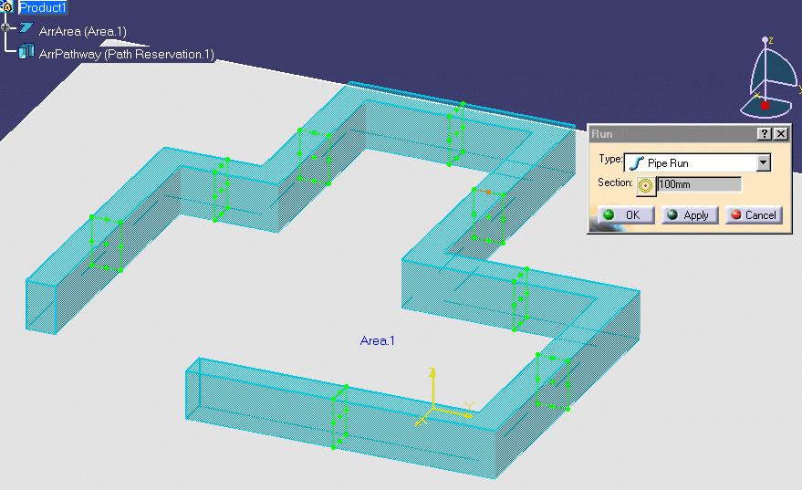
12 Routing a Run This task describes how to create a piping run. In this case, a run represents the actual path of the piping segment through the plant, ship or structure. See Routing a run on an area for more information. 1. Click on the run button. The Routing dialog box is displayed. 2. Click the Mode buttons to select the setting most suitable for the design; Point-To-Point, Orthogonal, Slope or Directional. This may take some trial and error to establish your preference. 3. Click the Section button to set the desired section shape to no section, rectangle or circle. 4. Under Section Parameters select the SetPoint most suitable for the piping run. Section dimensions, Turn radius and Minimum length fields display the values given to the Line ID being used. The Display buttons allow you to select a display mode of Line/Curve, Solid, or Flat. 5. Click OK. 6. Click at 0,0,0 to start routing the piping run. 7. Click at 0,3000mm,0 to create the first segment of the piping run. 8. Click at 3000mm,3000mm,0 to create the second segment of the piping run. 9. Double click at 3000mm,0,0 to complete the definition of the piping run. 10. You have created a routing with one piping run. Each piping run you route will show as ArrRun.X, X being a unique number. You can now create additional runs using the steps described above, or you can go on to the task of placing parts on the run.
13 Flipping Elements This task shows you how to flip a part that has been placed in your CATProduct drawing. 1. Click the Flip Part Position icon. 2. Select the part you want to flip. The part is flipped.
14 Changing the Current Axis This task shows you how to change the current axis. When you activate an element, the current axis is reset to the axis of that element. Changing the current axis changes the reference point by which elements are routed and placed. 1. Click the Change Current Axis icon. 2. Select the element you want to use as a reference. The axis for the selected element is displayed.
15 Basic Tasks The basic tasks for creating documents using the Piping Design product are explained here. Manage piping lines Routing runs Modifying runs Manipulating objects Query/modify properties of an object Modifying a piping part
16 Managing piping lines The following section explains ways of managing piping lines. Renaming a line ID Deleting a line ID Import a line ID Modify properties of a line ID Querying a line ID or its member Selecting a line ID or its member

17 Renaming a line ID This task shows you how to rename a line ID. Only shared line IDs can be renamed. 1. Click on the Rename Line ID button. The Renaming Line IDs dialog box displays, with a list of line IDs showing. 2. If you want to search for other line IDs then scroll through the list or enter a keyword in the Filter String field. 3. Select the line ID you want to rename. The Rename Line ID dialog box displays. 4. Enter the new name for the line ID and click OK.
18 5. Click OK again in the Renaming Line IDs box. The line ID will be renamed.


19 Deleting a line ID This task shows you how to delete a line ID 1. Click the Delete Line ID button. The Delete Line IDs dialog box displays showing all the line IDs contained in your document. 2. Select the line ID which you want to delete. (When you select a line ID all members that belong to it are highlighted.) 3. Click Delete. If the line ID you selected has any members a message will display alerting you that all members belonging to that line ID will be deleted. 4. Click OK. The line ID and all its members will be deleted.
20 Only line IDs contained in your document will be deleted. The same line ID used in other documents will not be deleted unless you open those documents and follow the steps given above.
21 Import line IDs This task shows how to import and/or update piping line IDs. The Import Line ID feature offers the user the utility of importing Line IDs from existing databases in other CAD software products. The Update feature allows you to update the properties of existing line IDs with properties contained in an XML import file. Installation of the Document Type Definition (DTD) and knowledge of XML are prerequisite to using this feature. The file format for the Line ID XML Import File resides in the DTD. The location of the DTD and sample XML file is platform dependent. In Windows NT the path for the DTD is...\intel_a\code\dictionary\plantshiplineidimport.dtd. For the XML file, the path is...\intel_a\startup\equipmentandsystems\piping\sampledata\pipinglineidimportsample.xml. The paths for the other platforms are identical with the exception of the platform identifier. Shown below are the platforms with their respective identifiers. Windows:...\win_a\ AIX:.../aix_a/ HPUX:.../hpux_a/ IRIX:.../irix_a/ SOLARIS:.../solaris_a/ In all cases, copy the PlantShipLineIDImport.dtd and the PipingLineIDImportsample.xml file to a local directory with 'write access'. In the following scenario both the sample XML file and the DTD have been copied to a user Temp directory. A portion of the sample XML file is shown below:
 with properties of Line IDs of the same name upon import.")

22 Be alert to any Line IDs you have created in CATIA as well as the Line IDs you will be importing. The properties of existing Line IDs in CATIA will be updated (replaced) with properties of Line IDs of the same name upon import. Prior to running this feature you must set a path for your Line IDs. Go to Tools + Options + Equipment & Systems. Click on the Line Lists tab and set the path for your Line IDs. 1. Click the Import Line ID button. 2. The Line ID Import/Update dialog box opens. Click to open the file. This will cause the subroutine to run which will generate the Line IDs from the XML file. Note that under Files of type, only XML files may be displayed and opened.


23 3. When the routine is complete, the Results Summary will display. 4. Click on View output file to view the Line ID Import/Update Report for the sample case below.

24 5. You can verify that the new line IDs have been imported by clicking on the Select/Query Line ID button. The Selecting Line IDs dialog box opens showing the updated and imported line IDs.
25

26 Modifying the properties of a line ID This task shows you how to modify the properties of a line ID. 1. With your document open, click the Select/Query Line ID button. The Selecting Line IDs dialog box displays, showing all the line IDs contained in your document. 2. Select the line ID whose properties you want to modify. 3. Under Selection Type select Line ID. 4. Click the Properties button. The Properties dialog box will display. Click on the Piping tab. 5. Enter your changes for the attributes and click OK.
27

28 Querying a line ID or its members This task shows you how to query a line ID or its members. When you query a line ID you are asking which members belong to it. When you query a member you are asking which line ID it belongs to. 1. Click on the Select/Query Line ID button. The Selecting Line IDs dialog box appears. 2. Use the Sort and Filter options if you need to. Under Filter, select the Local option if you only want to filter line IDs in the document. Select All if you want to filter all line IDs available to you. 3. To perform a query on a line ID click on the line ID in the Line ID list. The members of that line ID will be highlighted. To query a member click on it in the document. All members that belong to the same line ID will be highlighted and the line ID will be highlighted in the dialog box.
29
30 Selecting a line ID or its members This task shows you how to select a Line ID or its members. You can edit the properties of line IDs or their members after selecting them. 1. Click the Select/Query Line ID button. The Selecting Line IDs dialog box displays. 2. Use the Sort and Filter options if you need to. Under Filter, select the Local option if you only want to filter line IDs in the document. Select All if you want to filter all line IDs available to you. 3. If you are selecting line ID members then select Line ID Members under Selection Type. If you want to select a line ID then select Line ID. 4. Click on a line ID in the Line ID list or click on one of the members. Either the line ID or the members will be selected, depending on the selection you made in Step 2.
31 Routing runs Routing runs, including routing runs in special circumstances, are explained here. Routing a run on an area Routing from the end of a routable Branching a run Routing a run at a slope Auto-route between equipment Route a run within a pathway Routing from an item reservation Display information about routables
32 Routing a run on an area This task shows you how to create a run on an area. You can begin routing a run from: Space. An object, such as a tube. The end of a run or middle of a run. A point. Connectors. Item reservation face. 1. Make the appropriate element (area, system or line) active by double-clicking in the specifications tree. 2. Select the Route a Run icon. The Run dialog box is displayed.

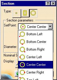
33 3. Define the routing mode for the run: Point-to-point Orthogonal Slope routing Directional routing 4. Define the Section parameters: a. Select the Section Type icon.. The Section dialog box is displayed.
34 b. Define the section type and corresponding parameters for each of them: No Section Rectangular Set Point Height Width Display Circular Set Point Diameter Display c. Select OK on the Section dialog box. Instead of entering the type of run, the set point and the height, width or diameter in the Section dialog box, you can select an existing run in your document. Once selected, the Section dialog box will display the values for that run. To select, click on the Run button and then click on the run whose values you want as the default. Make sure the entire run is selected - not just a segment or a node. It will be easier to select the run in the specifications tree. 5. Optional. Enter a value for the turn radius. 6. Optional. Enter a value for the minimum length. The turn radius and minimum length are governed by the nominal size you select - you will not be able to enter a different value. The turn radius and minimum length for that nominal size are in turn governed by the Rules table.
35 If you enter a minimum length or turn radius you will not be able to route correctly unless these values are satisfied. For instance, if you enter a minimum length of 10 feet, you will not be able to complete a segment that is 5 feet. In the illustration below, the green line shows the minimum segment length that will be created, even if you try to make a shorter segment, because the minimum length you entered is longer than the segment you are now trying to create. Similarly, if you enter a value for the turn radius, your run will automatically be adjusted to satisfy the defined turn radius. 7. Click in the drawing to define the routing points. 8 Double-click on the last point to stop routing. You can also click OK in the Run dialog box to stop routing. Click Cancel to abort your routing. 9. Click on the Close Loop symbol that shows at the beginning of the run if you want to create a closed loop run. In a closed loop run the ends of the run are joined.
36 Routing from the end of a routable This task explains how to route from the end of a routable. If you route an element with the same type and parameter values as the "source" element (i.e., the element from which the routable is routed), you can specify whether the new element is a continuation of the source element or a separate element. If you want to use the "Continue" option, be sure that the parent for the source element is active before you begin. 1. Select the Route a Run icon 2. The Routing dialog box is displayed. Define the routing parameters. See Routing a run on an area for instructions. 3. Select the element from which you want to route. For routables that are displayed with no section, select the filled circle displayed when the cursor is at the end point of the line. For routables that are displayed with a section, base your selection on the "cues" that are displayed as you move the cursor over the element: An outlined circle is displayed when your cursor is over the end point of the section centerline. A filled circle is displayed when the cursor is over the end point of the support line (defined by the set point of the section). If you want to route the run as a continuation of an existing element, select the filled circle (i.e., the support line). If the new element you route has the same type and parameter values as the element you selected, these options are added to the Routing dialog box: Continue Routing Create New Route 4. Select the appropriate Continue option.
37 5. Click in the drawing to define the routing points. 6. Double-click on the last point to stop routing.
38 Branching a run This task explains how to route a run that branches from any of these elements in a drawing: Another run Boundary Contour Equipment Pathway If the "source" element (i.e., the element from which the run branches) is moved or resized, the run is adjusted accordingly. 1. Select the Run icon. The Routing dialog box is displayed. 2. Define the parameters for the run. See Routing a run on an area for instructions. 3. Select the element from which you want to route the run. For a contour, select the edge. For an equipment, select an alignment vector. For runs that are displayed with a section, base your selection on the "cues" that are displayed as you move the cursor over the element: A dashed line is displayed when your cursor is over the center of a section. A solid line is displayed when the cursor is over the support line (defined by the set point of the section). If you want to create a run that "branches" from the end of a run, see Routing from the end of a routable.

39 Routing a run at a slope This task shows you how to route a run at a slope. 1. At the point in your run at which you want to slope it click the Slope button in the Run dialog box. 2. Enter the degrees of slope you want. 3. Click the Section button and enter data about the type and size of run. 4. Continue creating your run. Click once to define the ending point of the segment. Click twice to end the run.
 active by double-clicking in the specifications tree. 2. Place the two pieces of equipment you want to connect on your area. 3.")
40 Auto-route between equipment This task shows you how to auto-route a run between two pieces of equipment or two connectors. 1. Make the appropriate element (area, system or line) active by double-clicking in the specifications tree. 2. Place the two pieces of equipment you want to connect on your area. 3. Click on the Route a Run button and enter parameters in the dialog box that displays. 4. Move the cursor to the first equipment - an arrow displays at the connector point. If the equipment has more than one connector point the arrow will display at different points as you move your cursor. 5. Click to select the starting point of the run. 6. Move the cursor to the second equipment, where the arrow will also display, and click to select the ending point of the run. The run is created over the shortest possible path. 7. Press the shift key to see other possible routes for the run between the two objects.
41 This task shows you how to route a run within a pathway. Route a run within a pathway 1. With your pathway model open, click on the Route Thru a Pathway button. 2. From the Section dialog box, select the type of run, the set point and other options. 3. Click on the pathway in which you want to route your run. This displays set points on the pathway. Select a position for the run by clicking on one of the points. For example, if you select Top Center the run will align to the top center of the pathway. You can click Apply in the Run dialog box to see how the run looks and to try different positions. Click OK when you are finished.
42

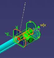
43 Routing from an item reservation This task shows you how to route from an item reservation. 1. Click the Route a Run button. 2. Click on the face of the item reservation from which you want to route. 3. Begin routing. The point on the item reservation face from which the run will start depends on the set point of the run. In the illustration above the set point is set at Center Center. If the set point was set at Bottom Center the run would have started at the bottom center edge of the item reservation. To change the set point, click on the Section Type button in the Run dialog box and select a set point from the drop down list in the Section dialog box that displays.
44
45 Display information about routables This task shows you how to display information about routables. It works only when you are performing an action with a routable, such as placing a part, branching a run or creating an offset route. 1. Click the Toggle Analysis Mode button. 2. Place the pointer over the run. When a segment is highlighted the length will be displayed. If a node is highlighted, the angle between two adjacent segments, the coordinates of the node, and the bend radius (if there is one) will be displayed. 3. Click the button again if you do not want to see the information.
46 Modifying runs Runs can be modified in the following ways. Changing a section Changing the angle of a segment Moving nodes Align adjacent segments Connect runs Disconnect runs Make segment parallel to reference plane Make segment parallel to compass base plane Make segment parallel to Z axis Fit segment for parts assembly Position a segment relative to plane Create an offset connection between segments Create a closed loop run Open a closed run Adjust extremeties of a run
47 Changing a section This task explains how to change parameters that control how the section of an element is displayed. 1. Place your cursor over the element and click the right mouse button. 2. From the pull-down menu, select the element or object you want to modify and select Definition. The Run Definition dialog box is displayed. 3. Click the Section button to set the desired section shape to no section, rectangle or circle. 4. If you select Rectangular Section, you can define or change these parameters: Set Point Height Width Display If you select Circular Section, you can define or change these parameters: Set Point Diameter Display 5. Click OK on the Section dialog box and OK on the Definition box to complete the change..

48 Changing the angle of a segment This task shows you how to change the angle of a pathway, boundary, or run segment. 1. Place your cursor over the element and click the right mouse button. 2. From the pull-down menu, select the element, or object, you want to modify and select Definition. The Run Definition dialog box is displayed. 3. Place the cursor over the support line for that element and click the right mouse button. 4. Select Definition from the pop-menu. The Segment Definition dialog box is displayed. 5. Specify a new value for the Turn Angle. A line is displayed in the drawing to show the new position for the segment. 6. Select OK on the Segment Definition dialog box. 7. Select OK on the Run Definition dialog box to complete the change. 8. To align a section's normal with the compass Z axis: Bring up the Definition box for the section. Place the compass on a 3-D element and adjust the Z axis to the angle you want. Right click on the segment. A pop-up menu will show. Click on Rotate section to compass Z direction. The normal of the section will rotate to align with the Z axis, as shown in the image below.
49

50 Moving or deleting a node This task shows you how to move the nodes on a path reservation, boundary, or run. In the example below a node will be moved in a pipe run. 1. Place your mouse pointer over the element and click the right mouse button. 2. From the menu that displays, select the element you want to modify, in this case pipe run.1 object, and select the Definition option. This will bring up the Definition dialog box. Symbols are displayed on the pipe run to show the location of nodes: asterisks represent non-connected nodes, and Os (circles) represent connected nodes. 3. To move a node by entering coordinates, do the following: Right-click the node symbol and select Definition from the pop-up menu. The Node Definition dialog box is displayed. Key in new values for X, Y, or Z. Click OK in the Node Definition dialog box. 4. To move the node using the cursor, place the cursor over the node symbol and drag it to a new location. See below.


51 A line is displayed to show the new location for the segment. 5. Click OK in the Definition dialog box to complete the change. A node will move parallel to the compass base plane, which is normally XY. To move a node vertical to the base, change the compass base to the XZ plane. 6. To move a node parallel to the compass Z axis. Bring up the Definition box for the routable. Place the compass on a 3-D object where it can be manipulated. Change the Z axis to the desired direction. Click on the square around the node and move it with the mouse button depressed. It will only move parallel to the compass Z axis. If you click on the node itself you will be able to move it in any direction. 7. To move a node of a routable to the origin of the compass. This allows you to move the compass to a specific point on a routable or resource, and then move the node to it. To do this: Bring up the Definition box for the routable which has the node you want to move. Move the compass to the point where you want the node to move. Bring up the Definition box for the node that will be moved. Click the Compass Origin button shown in the image.. The node will move to the compass base, as
52 8. To delete a node right click on the node and select Delete Node from the pop-up menu that displays.

53 Align adjacent segments This task shows you how to align adjacent segments which have become out of alignment. Segments can get out of alignment when a node is moved in a non-planar manner. In the illustration below the joints marked in red have been moved out of alignment. 1. Bring up the Definition dialog box for the run. 2. Right click on the segment half closest to the misaligned joint. If more than one joint is misaligned click on a segment half closest to one of the end joints. A drop down menu will appear. 3. Click on Align adjacent segments in the drop down menu. All segments will align beginning at the joint closest to the segment handle you selected. Segments will align in one direction only. If there are other misaligned segments in the run then you may have to repeat the operation.

54 Connecting Runs This task shows you how to connect a routable to another routable. A routable may be a path reservation, space reservation, boundary, or run. There are two kinds of connection: branch, and end-to-end. In a branch connection the end of one element connects to the middle of another. In an end-to-end connection two ends connect to each other. In the examples below, the two path reservations will be connected to each other, first as a branch connection and then as an end-to-end connection. When you connect two elements one becomes the Slave while the other becomes the Master. In the example above, if you make the one on the right the Slave and the one on the left the Master, then, after you connect them, the Slave will follow the Master to maintain the connection if you move the Master. 1. Place the mouse pointer over the element you want to designate the Slave and click the right mouse button. 2. From the pull-down menu that displays, select the element you want to modify, in this case Path Reservation, and select the Connect Routes option. (You can also click Edit and then the element, in this case Path Reservation, and select Connect Routes.) 3. To make a branch connection select the Master Connector. To select, move your mouse pointer over the routable you wish to designate the Master and click on either the support or center line connector. See Information below.
. The second routable will connect to whichever line you select.")
55 When you move the mouse pointer over the path reservation you will see two lines alternatively, as you move the pointer from bottom to top. The solid line is the support line or set point connector, and the dashed line is the center line connector (illustrated below). The second routable will connect to whichever line you select. Select the line by clicking. 4. Select which end of the Slave you want to connect to the Master. The Slave will connect with the Master after you click. The two elements will connect at the point where the two support or center lines would intersect. If you want to change the position then see Moving Nodes. 5. To make an end-to-end connection replace Step 3 above with the following: Select the Master Connector. To select, move your mouse pointer over the routable you wish to designate the Master and click on the arrow that displays at whichever end you want to connect. As you move the pointer up and down the arrow will move, depending on whether the pointer is over the support or center line connector, as explained above.

 node symbol is displayed on the path reservation where it is connected to the other element.")
56 Disconnecting Runs This task shows you how to disconnect a routable that is connected to another routable. A routable is a path reservation, space reservation, boundary or run. 1. If it is a branch connection then select the Slave element, in this case a path reservation. If it is an end-to-end connection then you can select either Master or Slave. 2. Click the right mouse button on the element you selected. From the pull-down menu that shows, select the element you want to modify, in this case path reservation, and select the Definition option. The Definition dialog box is displayed, and an O (circle) node symbol is displayed on the path reservation where it is connected to the other element. In the illustration below the mouse pointer is pointing to it. 3. Right-click the node symbol. A pop-up menu shows. Select Disconnect. 4. Click OK on the Definition dialog box. The two elements are disconnected.
57

58 Make segment parallel to reference plane This task shows you how to make a segment of a run parallel to a reference plane. You can place the Offset Plane on a surface to make it the reference plane, and then make a segment of a run parallel to the reference plane. In the illustration below, a reference plane will be placed on a face of the item reservation, and a segment made parallel to it. 1. Click on the Offset Plane button and then on the face where you want to place it. A square shows on the face. 2. Bring up the Definition dialog box for the run. 3. Bring up the Definition dialog box again, this time for the segment half you are interested in. See note below.

59 Each segment is divided into two halves, which become visible when you bring up the Definition dialog box for the run. It is important to select the segment half correctly because the segment will pivot at the node closest to the segment half you select. 4. Click on the Reference Plane button in the Segment Definition dialog box. The segment will pivot - at the node closest to the segment half you selected - to become parallel with the reference plane. In the illustration above, the portion in red was the segment half selected. If the half to the left of it had been selected then the segment would have pivoted at the node to the left of it, as shown below. 5. Click OK and then OK again in the Definition dialog box.
60

61 Make segment parallel to compass base plane This task shows you how to make a segment of a run parallel to the compass base plane. Also see Make segment parallel to reference plane. 1. Drag the compass and place it on the surface to which you want to align the segment. 2. Bring up the Definition dialog box for the run. 3. Bring up the Definition dialog box again, this time for the segment half you are interested in. See note below. Each segment is divided into two halves, which become visible when you bring up the Definition dialog box for the run. It is important to select the correct half, because the segment will pivot at the node closest to the segment half you select.

62 4. Click on the Compass Base Plane button. The segment will pivot - at the node closest to the segment half you selected - to become parallel with the reference plane. In the illustration above, the portion in red was the segment half selected. If the half to the left of it had been selected then the segment would have pivoted at the node to the left of it, as shown below.

63 Make segment parallel to Z axis This task shows you how to make a segment of a run parallel to the compass Z axis. See also Make segment parallel to reference plane. 1. Drag the compass and place it with the Z axis pointing in the direction with which you want to make the segment parallel. 2. Bring up the Definition dialog box for the run. 3. Bring up the Definition dialog box again, this time for the segment half you are interested in. See note below. Each segment is divided into two halves, which become visible when you bring up the Definition dialog box for the run. It is important to select the correct half, because the segment will pivot at the node closest to the segment half you select. 4. Click on the Compass Z Direction button. The segment will pivot - at the node closest to the segment half you selected - to become parallel with the Z axis of the compass. NOTE: Place the compass carefully because segments also have a directional relationship to the compass. The node that pivots will parallel the base of the compass. The node at the other end will parallel the Z vector.
64
65 Fit segment for parts assembly This task shows you how to adjust a segment for parts assembly purposes. It can be used to move one part next to another, or to place two bends next to each other to create a U. In this example the segment half to the right will be shortened so that the elbow is placed against the tee. 1. Bring up the Definition dialog box for the routable. 2. Right-click on the segment half that you want to shorten. A drop down menu will display.


66 3. Click Adjust to fit. The elbow will move flush against the tee. The same command can be used to create a U. If you have a segment with bends at the two ends and you use the command described above, the segment will shorten so that the two bends are adjacent. It will not work if there are no bends.

67 Position a segment relative to plane or to another segment This task shows you how to position a routable segment so that it is a defined distance away from a reference plane or from another segment. This function can be used to make a segment clear an existing structure or in situations where it is necessary to position a segment a specified distance from another object or segment. 1. In the example below, the routable is colliding with the beam. The task is to move the segment up so that it passes just over the beam. 2. Place the offset plane on top of the beam and bring up the Definition dialog box for the routable. 3. Right-click on the segment you want to move. A drop down menu will display. Select Offset segment.


68 4. Select Offset segment. The Offset segment dialog box will appear. 5. Select Make segment parallel to reference plane and then select one of the buttons, Outside edge to reference plane or Center line to reference plane. See Step 9 to offset to another segment.
69 6. Enter a distance in the Offset field. If you enter 0 the routable will be placed on top of the beam if you have selected Outside edge to reference plane. If you select Center line to reference plane then entering 0 in the Offset field will place the center line of the routable on top of the beam. 7. Click the Offset to far side or Offset to near side button. These buttons will place the routable on either side of the reference plane. 8. Click Preview if you want to, then click OK and then OK again in the Definition dialog box. The run segment will be placed on top of the beam. 9. To position a segment a certain distance from another segment, select the Offset to another segment option and click the segment to which you want to offset. Click one of the three buttons: Outside edge to outside edge, Center line to center line or Center line to outside edge.

70 Create an offset connection between segments This task shows you how to create an offset connection between two segments. Creating this connection makes a master-slave relationship between the two and maintains a fixed distance between them. If you create the connection only between two segments, the two will maintain the offset if you move one. But other segments of the slave routable may change in length to allow the offset to be maintained between the two segments that have a connection. If you do not want this to happen you can create a connection between the other segments too. 1. Click the Create an offset segment connection button. The Run dialog box displays. 2. Select the segment you want to be the slave. The first segment you select becomes the slave, while the second becomes the master. 3. Select the second segment. The compass displays and you can see a connector line between the two.


71 4. Enter the offset distance and select your offset between options in the Run box. You can choose to have the offset connection between the: Outside edge to outside edge Centerline to centerline Outside edge to centerline 5. To create a connection between other segments of the same two routables select other segments in the same sequence given above. 6. Click OK. The connections will be created. 7. To modify the connection, select the slave run, click the Create offset segment connection button, select the slave segment and enter your changes. 8. To delete offset connections select the slave routable, right click, then click on the line corresponding to the routable and click Delete offset connections. All connections between the two routables will be deleted.
72


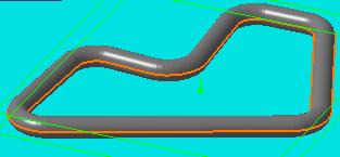
73 Create a closed loop run This task shows you how to modify an existing run in order to create a closed loop run. In a closed loop run the ends of the run are joined. There are two ways of turning an existing run into a closed loop run. Both are explained below. 1. Click on the Run button and continue routing from the end of the run. 2. Click the Continue Routing button in the Run dialog box. 3. Click on the other end of the run when finished. The ends of the run will join to form a closed loop. 4. In the second method, right-click on the run and, in the drop down box that appears, click on the line that describes the run, in this case Run.1 Object. 5. Another drop down menu will display. Click on Close Route. 6. The two ends of the run will join. An open end run and closed loop run are shown below.
74


75 This task shows you how to open a closed run. You can only open a closed run at a node. Open a closed run 1. Bring up the Definition dialog box for the run. 2. Click the right mouse button on the node where you want the run to be opened. This will display a drop down box. 3. Click on Open. The run will open at the node.
76

77 Adjust the extremity of a run This task shows you how to move or adjust the extremity of a run. 1. Right click on the segment whose extremity you want to adjust. From the menu, select the object, in this case 'Run2.1 object' and then select Definition. The run will be highlighted as shown below and the Definition dialog box will open. 2. Click and drag the connector symbol at the end of the section to reposition it. The image below shows the repositioned extremity. Notice that that Total length in the Definition dialog box has changed to reflect the adjusted length.


78 3. Click Apply and OK. The run will now extend to the selected position. [ Back ] [ Up ]
79 Manipulating objects This section explains some ways in which objects and resources are manipulated. Aligning elements Distributing elements Rotate resource using definition dialog box Snap resources together Snap and rotate a resource Using offset planes
80 Aligning Elements This task shows you how to align elements in your layout. You can align the center or the sides of an element to a user defined reference plane that you define. You can also rotate an element to align it with a reference plane. 1. Select the element(s) that you want to align. 2. Select the icon for the type of alignment you want to perform: Align Sides: aligns the sides of two or more elements Align Center: aligns along the centerlines of two or more elements Rotate to Align: rotates elements on the axis to align them Distribute: See Distributing elements 3. Define the plane to use as a reference for the alignment. If you have an offset plane already defined it will be used as the reference plane. If you do not already have the offset plane defined do the following: a. Place your cursor over a geometric element that defines the plane (e.g., a construction plane, boundary, area contour, item reservation). As you move the cursor, a small white rectangle is displayed to show the selectable planes, as shown below. A line normal to the rectangle shows the direction in which the alignment would be performed.

81 If you do not see the white rectangle, zoom out from the drawing. The white rectangle cannot be displayed if the element under your cursor is displayed too small. b. Click to select the plane. 4. The selected elements are aligned along the plane. 5. Click any button in one of the tool bars to exit the alignment command. If you want to continue with the alignment command using the same reference plane then select another element in the model.
.")
82 Distributing Elements This task shows you how to distribute elements within parameters that you define. 1. Select the elements you want to move. 2. Select the Distribute icon. 3. Define a reference plane for the distribution by doing the following: a. Place your cursor over a geometric element that defines the plane (e.g., a construction plane, boundary, area contour, item reservation). As you move the cursor, a small white rectangle is displayed to show the selectable planes, as shown below. A line perpendicular to the rectangle shows the direction in which the distribution would be performed. If you do not see the white rectangle, zoom out from the drawing. The white rectangle cannot be displayed if the element under your cursor is displayed too small. b. Click to select the plane.

83 The selected elements are distributed along a line perpendicular to the plane, as shown below. [ Back ] [ Up ] [ Next ]
 3.")
84 Rotate resource using the definition dialog box This task shows you how to rotate a catalog resource by entering into the definition dialog box the number of degrees that you want it to rotate on its vertical axis.. 1. Click on the resource. 2. Click Edit-Definition in the menu bar. This displays the Product Definition dialog box. (You can also enter Cntrl-Enter to display the box.) 3. Enter the degrees in the Rotation field. 4. Click Apply and the resource will rotate on its vertical axis.

85 Snap resources together This task shows you how to snap two resources together. Resources can be joined at existing connectors, you can create new connectors to join them, or you can snap them together without using connectors. All procedures are described below, beginning with the procedure for snapping resources in which you create connectors. To snap resources together by creating new connectors, click the Snap button Click one of the resources you want to snap together. The resource changes color and the Define Reference Plane (From) dialog box displays.
.")
86 By default the Define Plane button is selected, allowing you to select a plane for the connector you will create. The two resources will have a Master-Slave relationship to each other - but only if you choose to add a constraint (see below). If you add a constraint the first object you select becomes the slave, and the second object becomes the master. Also note that the first resource you select will move to snap - the second resource you select remains stationary. 3. Select the origin, plane and other criteria. Click the Define Plane button to redefine the plane as well as the origin by clicking once on the face. Click the Define Plane using Compass button to redefine the plane using the compass. Click the Define 3-point plane button to define the plane by clicking on any three points with your pointer. The connector will be placed on the first point you click. Click the Define Line-Point Plane button to select the plane by clicking on a point and a line, like an edge. The connector will be placed on the first point you click. Click the Define Line-Line button to select the plane by clicking on two lines. The plane will be defined by the first line selected. But if the two lines are parallel the plane will be defined as the plane in which both lines exist. Click the Define Origin button to place the origin of the connector. The plane and orientation will not change.


87 Click the Define Orientation button to change the orientation of the arrow parallel to the plane. Click the button and then click a point or a line. If you click a point the arrow will point to it. If you click a line the arrow will become parallel to the line. Click OK when done. See Creating connectors for more information on connectors. 4. Select the second resource. The Define Reference Plane (To) box will display - make your selections as explained above. You can also select an existing connector. Click OK when done. The two resources will snap together and the Constraint Options dialog box will display. 5. You can clear the Align, Face and Orientation check boxes and click OK if you want the two resources to remain snapped together without any new connectors being created. To add one or more constraints - which will also result in creating connectors - follow the steps given below. 6. Make your selections in the Constraint Options box. Align: You can increase distance between the two resources, but if you change the alignment the slave will snap back to the original alignment. In the image below the distance is increased but the alignment remains the same.


88 Face: The two resources will maintain the face if you move one of them. In the image below the two maintain the same face, though the alignment has changed. Orientation: The two connectors will maintain the same orientation if you move them, i.e. the red arrows visible in the connectors will align. It is therefore important to make sure that the red arrows in the connectors are pointed correctly and oriented correctly with reference to the part. The red arrow is usually set to the "Up" position of the resource, which means that on both resources they should point in the Up direction. If the red arrow points "down" in one resource and "up" in the other, then the resources will snap together incorrectly. You can toggle the position of the red arrow by clicking on the green arrow that is parallel to the plane. In the image below, the red arrow is pointed in the "up" direction of the chair as well as the table. Fix in space: If you select this option the position of the master resource
89 is fixed - if it is moved it will snap back to its original position. To remove a constraint select it in the specifications tree and delete it. To remove the Fix in space option right click on the Fix line in the specifications tree, click Properties, go to the Constraints tab, and uncheck the Fix in space box. 7. Click OK when done. 8. To snap resources together using preexisting connectors:. b. c. d. Click the Snap button. Move the pointer over the first resource - the connectors will display. Select the connector. Move the pointer over the second resource - the connectors will display. Select the connector and the two resources will snap together. The Constraint Options box will display. Make your selections and click OK.


90 Snap and rotate a resource This task shows you how to rotate a resource after snapping it to another resource. 1. With both resources on the screen, click on the Snap orientation symbol will appear. button and then on a resource. The 2. Click on the second resource. A white square will appear. Move the pointer over the resource and click when the white square is at the location where you want to snap the two resources. The orientation symbol will appear at the location and the Define Reference Plane dialog box will display. 3. Click on the Define plane using compass button location where you want to snap the two resources.. The compass will be placed at the


91 4. Click OK on the Define Reference Plane box. The two resources will snap together. 5. Click on the Select button to exit the Snap command. Click on the resource you want to rotate, then grab one of the handles on the compass with your pointer and move it. Different handles will move/rotate the resource in different directions. You can also double click on the compass to bring up the Compass Manipulation dialog box and enter the required figure in the Angle field. Click on the Plus or Minus sign next to the Z axis to rotate it.

92 Using offset planes & advanced offset planes This task shows you how to define a plane to use as a temporary reference for positioning other elements. The second part of the document explains the use of an advanced offset plane, which allows you to define origin, orientation and other parameters. 1. Select the Offset Plane icon. 2. Define the reference plane by doing the following:. Place your cursor over a geometric element that defines the plane (e.g., a construction plane, boundary, area contour, item reservation). As you move the cursor, a small white rectangle is displayed to show the selectable planes, as shown below. If you do not see the white rectangle, zoom out from the drawing. The white rectangle cannot be displayed if the element under your cursor is displayed too small. b. Click to select the plane. The white rectangle changes to a blue rectangle, and remains displayed on the reference element, as shown below.
93 The reference plane can now be used as a reference to position other elements. 3. Use the advanced offset plane feature to set your plane reference, origin and orientation settings as follows:. Click the Advanced Offset Plane button. will display. The Define Plane dialog box b. The Define Plane button is selected by default. However, you can select any button in the Define Plane box. Click when you have found a location. The plane manipulator displays.
94 c. Click on the buttons in the Define Plane dialog box to make your selections. Click the Define Plane button to redefine the plane as well as the origin by clicking once on the face. Click the Define Plane using Compass button to redefine the plane using the compass. Click the Define 3-point plane button to define the plane by clicking on any three points with your pointer. Click the Define Line-Point Plane button to select the plane by clicking on a point and a line, like an edge. Click the Define Line-Line button to select the plane by clicking on two lines. The plane will Clicking the Define Origin button will display the Define Origin box. You can select from one of three options provided by the drop down menu: Plane or Compass, Point or Center of Face and Center of Circle. Plane or Compass allows you to define the origin using the compass or plane command. You use the compass or plane as the base plane along which the origin can be selected. Point or Center of Face lets you select the origin by clicking on a point or face. Center of Circle allows to select the origin by clicking at three points - the origin will be placed in the center of an imaginary circle drawn using those three points. The plane and orientation will not change when using this command. d. Click the Define Orientation button to change the orientation. Click the button and then click a point or a line. If you click a point the X axis will point to it. If you click a line the X axis will become parallel to the line. Click OK when done. The reference plane will be created.
95 Query or modify the properties of an object This section explains ways of querying and modifying the properties of objects. Edit properties of an object Filter shown properties of an object Rename an Object
96 Edit or display the properties of an object This task shows you how to edit or display the properties of an object. 1. Select the component. 2. Click Edit - Properties or, as an alternative, right-click and select Properties. The Properties dialog box appears with the properties displayed under various tabs.

97 The Properties dialog box will display tabs, most of which are used in all CATIA products. The Graphic tab allows you to change the appearance of the object. Under the Product tab you can include additional descriptive and historical data and make changes, such as renaming, to the basic Product in the specifications tree. See CATIA Infrastructure documentation ( Basic Tasks - Manipulating Objects - Displaying and Editing Graphic Properties) and Product Structure documentation (User's Tasks - Modifying Component Properties) for more information. Click the More button if you want to see other tabs. 3. Enter values in the fields as desired and click OK. The properties will be edited. 4. Click OK to end. Some objects have discrete values - which means you may only select certain values. In that case you will be able to display a drop-down box and select one of the values in it.

98 Filter the properties of an object This task shows how you can filter the properties of an object. Filtering the properties means you can choose to display or hide any of the properties shown in the Properties dialog box. You can only filter properties that are unique to Piping Design and Tubing Design objects. 1. Click the Filter button on the Properties dialog box (Edit or display properties of an object). The Attribute Filter box displays. 2. Click on each property to toggle between Display and Hide. An X next to a property means it is displayed. The settings will be retained when you open the Properties dialog box again.
99 Renaming objects This task shows you how to rename objects. You can rename components and runs using this command. 1. With your document open, click the Rename button dialog box displays.. The Rename 2. Select a component or run. The existing name of the object will appear in the New Name field. 3. Enter the new name in the New Name field. If you want to rename other objects click Apply and continue renaming. 4. Click OK when finished. The objects will be renamed. Using this command to rename a component does not rename all instances of that component. If you have placed a component more than once in a document, and want to rename all of them, you will have to rename each one.
100 Modifying a piping part Ways of modifying a piping part are discussed in this section. Rotate a piping part


.")
101 This task shows you how to rotate a piping part. Rotate a piping part A piping part can only be rotated if it is in free space - connected components cannot be rotated. 1. With your component displayed, click and drag the compass and place it on the part you want to rotate. 2. Move the pointer to the highlight the compass for the desired direction of rotation. 3. At this point there are two methods of rotating the part. If you know the exact amount of rotation required, double click on the highlighted arc (visible in Step 2). The Compass Manipulation dialog box opens. Enter the exact amount of rotation in the desired axis; in this case the Y axis. Click Apply new position and then Close. The alternate method is to grab the compass and rotate the part to the desired degree of rotation.
102
103 Advanced Tasks Advanced tasks are discussed in this section. Routing tasks Building piping parts Connectors
104 Routing tasks This section explains some routing tasks that are in addition to the ones explained in the Basic Tasks section. Aligning a run Routing in 3D with the compass Routing at an offset of a routable Route a run along a spline Fix broken routables

105 Aligning a run to an existing surface This task shows how to align a run to an existing surface or edge while in directional routing mode. This function uses the compass to align a run to the surface or edge. It is assumed that you have taken the steps necessary to start a run. See Routing a Run on an Area. 1. In the directional routing mode move the compass that shows at the end of the run to the edge whose angle you want to emulate. 2. The Z axis of the compass (it may read W) assumes the angle of the edge against which it is held. 3. At the same time the last segment of your run assumes the angle of the compass' Z axis. 4. Click once at the end of the segment to move the compass back to it. You can repeat the action to make the run align with any other edge or surface in the area. 5. Double click to end the run.

 is pointing in the direction in which you want to route.")
106 Routing in 3D with the compass This task shows you how to use the compass to route in any direction, including vertically. 1. Click on the Route a Run button. The Routing dialog box is displayed. 2. Click on the Directional Routing button. 3. Select the type of run and enter other values. See Routing a Run for more details. 4. Click at the point where you want to start your run from. This places the compass at that point. To begin routing click and drag the compass so that its Z axis (it may read W) is pointing in the direction in which you want to route. Every time you want to change direction drag the Z (or W) axis of the compass. 5. Double click, or click OK, to end your routing.
107 You can also double click on the compass to bring up the Compass Manipulation dialog box, which allows you to enter values to modify compass direction and/or location.

108 Route a run at an offset of a routable This task shows you how to route a run at an offset of a routable. This function allows you to create a run paralleling an existing run, a defined distance apart. 1. Click the Create an Offset Route button. 2. Select a segment of the run to which you want an offset. The compass is placed on the segment. 3. The direction in which the Z axis of the compass is pointed determines where the new run will be placed: you can place the new run or runs to the inside, to the outside or stacked on top of the existing run by adjusting the compass. 4. Enter your options in the Run dialog box. 5. Click either the Constant Radius or Constant Clearance button. If you click the Constant Radius button the radius of the turns will be maintained but the offset may vary. If you click the Constant Clearance button the offset will be maintained but the radius of the turns may change. Click OK. The new runs will be created. A negative offset may be entered to offset in the opposite direction to the compass Z direction. In the illustration below the runs have been created with the Constant Clearance option.


109 Route a run along a spline This task shows you how to route a run along a spline. 1. Import the model which contains the spline into the Systems Routing workbench. 2. Click on the Route from Spline button. 3. Select type of run and enter other options. Note: The SAG option is used to define the maximum distance a segment can be from the spline. The run that is created consists of straight segments, as you can see in the illustration below. The smaller the SAG number entered, the closer the run will resemble the spline. But this will also cause more segments to be created. 4. Select Create connection to curve if you want a connection between the run and the spline. If this option is checked the run will move if the spline is moved. 5. Click on the spline. The run is created.
110

111 Fixing broken routables This task shows you how to fix - or rejoin - routables in which segments have become separated. In the illustration below, the dotted line - the broken routable indicator - shows that a run has become separated at that point. You can re-join the run in one of several ways, depending on the nature of the break and your requirements. The methods are as follows:

112 1. Bring up the Definition dialog box for the run, then place the mouse pointer over the broken routable indicator and click the right mouse button. This will display a pop-up menu. Click Create Segment. 2. Bring up the Definition dialog box, then drag one of the segment handles to re-join the run. 3. Bring up the Definition dialog box. An arrow will display at each end of the broken routable indicator. Drag one of the arrows (depending on circumstances) to re-join the run. In the illustration below, one segment of the run has been moved to connect to the portion of the run still connected to the pump.
 is broken. Select Auto Route. The Auto Route dialog box will display. Click on the Toggle button.")
113 4. In certain cases you will see the Auto Route option beneath the Create Segment option in the pop-up menu (See Step 1). This happens when a segment connecting two parallel routables (which are on different X-Y planes) is broken. Select Auto Route. The Auto Route dialog box will display. Click on the Toggle button. Options for re-joining the run will be shown as a dotted line. Click OK to make your selection.
114 Building piping parts This section explains ways of creating and using resources. Change the parameters of a part Create piping part with specified type Create graphic representations for a part Define properties for a part Associate specifications to a connector


115 Change the parameters of a part This task shows you how to change the parameters of a part. 1. Select a part, in this case an elbow at the end of a run, and click the Edit Part Parameters button. This will display the Parameter Explorer dialog box. 2. The box will display a list of parameters that can be edited for the part you selected. Select one of the parameters.

116 3. If it is possible to change this parameter by entering a value in the Parameter Value field then do so. If the Value field is grayed out then click the button to the right of it. 4. A dialog box will display, displaying the values that can be selected. Select one of the values. 5. Click OK to exit the dialog boxes. These are the only commands relevant to the change part parameter procedure. Other buttons and fields on the Parameter Explorer dialog box are meant for other functions and should not be used.
117 Create a part with specified type This task shows you how to create a part with a specified type. Before you create parts you should specify where they will be stored. A default directory is specified but if you change it see Defining directory paths. The parts are normally moved from this directory into the catalog. You should also create a graphic representations file and specify where it is located. (See Defining directory paths and Define graphic representations for a part.) 1. Click on the Build Piping Part button. The Create Part dialog box appears. 2. Click on the Display Class Browser button as shown above. The Class Browser appears.

118 3. The Class Browser allows you to select the type of piping part you want to create. Navigate to the type you want by clicking on the "plus" sign next to each directory, or by using the three navigation buttons at the bottom. You can also filter for certain types. For instance, you can enter "elbow" in the Filter field and hit enter to see all elbow types. Click OK when you have made your selection.

119 4. Enter a name for the part in the Symbol Name field and hit Enter. Click Apply or OK. The part will be created. In the illustration below it has been named Elbow1. The part has been created but it still does not have a graphic representation - it has no "looks". You will learn how to create one or more graphic representations for the part in subsequent tasks. 5. You must save the part to the directory specified in your Options dialog box. Double click on the part (Elbow1 in the image above) to make it active and then use the File menu to save it. The File Open button next to the Symbol Name field is used to bring up a part if you did not finish creating it and had to close the application. Using the File Open button you can navigate to the directory where the part is stored.

120 Define graphic representations for a part This task shows you how to create multiple graphic representations for a part. Once you have created a part and specified a type, you can create one or more graphic representations, which means create the body of the part. You can define multiple graphic representations of a component when you need to show more than one graphic of the same component. For instance, you may need to show a pipe as "double", which is like a 3-D version, as "single", which means represented by a single line, or "envelope", which also includes the working area needed around the pipe or equipment. These three categories are included with this application. A fourth category is also included, "exact", which is normally used for detailed representation and is used mostly for parts. You can create these three graphics of the same pipe and place whichever one you prefer in a document. Before you create multiple representations you should set up a Graphic Representations file. (See Defining directory paths for how to do this.) A Graphic Representations file allows you to classify in specific categories each graphic that you create. In addition to the four categories that come with the application and that were described above, you can create categories based on your specific needs. 1. When you create a part as explained in Create piping part with specified type, it is given the first classification that is listed in your Graphic Representations file. In this example it is Double, as shown in the illustration below. To start making graphic representations for the part, you will first create a graphic for the Double representation that you have already created. To do this double click on Elbow1 to bring up the Part Design product. (Not all users may have a license for Part Design - contact your system administrator.)
 You have now created the Double graphic representation of the part. 3. To create a second graphic representation, double click on Elbow1 (Elbow1.")

121 2. Create your part (in this case an elbow) using Part Design. (See Part Design documentation if you need help.) You have now created the Double graphic representation of the part. 3. To create a second graphic representation, double click on Elbow1 (Elbow1.1) to return to Piping Design. 4. Click on the Build Piping Part button to display the Create Part dialog box and click on the elbow to make it active. The buttons at the bottom of the Create Part dialog box will become active. 5. Click on the Manage Representations button. The Manage Graphic Representations dialog box will display.

122 6. Select one of the Graphic Names and then click Create. This will add the graphic name to the specifications tree. The value in the Defined column changes to Yes when you create that particular graphic representation. If the value for a graphic in the Activated column is yes it means you can see that graphic. (You can toggle between yes and no by clicking on it.) In the illustration below you can see both double and single representations. The single representation is the white line running through the 3-D elbow. Use the Associate button to change the name you have already assigned to a graphic representation. To do this, select the graphic name you want to change to in the Manage Graphic Representations dialog box, click the Associate button and then select the graphic, either in the viewer or in the specifications tree. 7. After you have added one or more graphic representations for that part, return to Part Design to create the graphic, as explained above.
123 Define properties for a part This task shows you how to add properties to a part. 1. With the part displayed click on the Build Piping Part button display the Create Part dialog box and then click on the Define to Properties button. The Define Properties dialog box will display.

124 2. Click on the Piping tab to display properties and enter the values you want to. 3. Click Apply or OK.

125 Associate specifications to a connector This task shows you how to associate specifications to a connector. You must associate specifications to a connector for the following attributes. Endstyle Nominal size Rating Schedule Wall thickness "Associating specifications" here means that you must enter how many sizes each of these attributes has. The reason for this is explained below. You can see from the image of the reducer below that because of its shape it is going to have two nominal sizes. The other attributes may have one or more entries. to a connector in these fields because a compatibility check is done when you place a part and these fields must have data or you will get an error message. Of course, you will also get an error message if the compatibility check determines that the part is incompatible in the situation where you are trying to place it - the wall thickness or the size do not match, for instance. You do not need to enter the size of the part, only how many sizes each of these attributes has. You must enter 1 if it has only one size. When you are placing the part at design time, the application will determine how many sizes you specified for, say nominal size. If you specified one size, it will determine what this size should be by examining the situation in which the part is being placed and then look at tables to determine whether you included that size in your catalog. 1. With the part displayed click on the Build Piping Part button box will display.. The Create Part dialog


126 2. Select the part and click on the Define Connector Specifications button. The Connector Specifications dialog box will display. In the illustration below, it shows columns for two connectors because there are two connectors on the reducer. 3. Enter your specifications by selecting the number in the drop down box next to each attribute. Click the Auto Assign button to assign the values to the connectors. They will display in the box as shown below.
127 4. You can modify the associated specifications by selecting in the Specification field. Select the attribute you want to modify and then select the number in the Specification field. For instance, if you want to change Connector 2 to Nominal size instead of Nominal size_2, select it and then select Nominal size in the Specification field. 5. Click OK when you have finished. You must save the file to the directory in which you store the parts that you create. See Create a part with specified type.
128 Creating and modifying connectors This section explains ways of creating, modifying and deleting connectors. Create connectors Use the compass to manipulate connector Modifying or deleting connectors Creating duplicate connectors Using the plane manipulator

129 Create connectors This task shows you how to create a connector. Connectors can only be created on objects that have existing geometry that satisfies the rules of connector creation. If existing geometry is not present then you must create the geometry. 1. If the resource is not active, make it active by double-clicking in the specifications tree. 2. Click on the Build Connector button. This will bring up the Manage Connectors dialog box. The Manage Connectors dialog box will list all connectors attached to the selected part. If you want to see the connector and its associated geometry on the part then click the entry. 3. Click on the Add button. The Add Connectors box will display.

130 The orientation, alignment and face must be defined correctly before a connector can be created. To explain what these are, the face is the surface to which you attach a connector. As an example, if you want to attach a clock to your office wall, the wall is the face. You want the numeral "12" to be up, so you orient the clock accordingly. This is the orientation. The alignment is the direction in which the clock face is pointed - normally it would be perpendicular to the wall. When creating a connector, the alignment always has to be perpendicular to the face. The face is generally defined using a face of the part, such as the end of a pipe. Alignment is usually defined using a line, such as the not-shown line along the centerline of a pipe. Orientation is defined using the xy plane, or another plane or face to define an "up" direction. In the illustration below the Z axis indicates the alignment of the connector. It also indicates the direction in which routing will occur. The X and Y axis together define the orientation. They are useful when attaching two resources.
131 It is necessary to select geometry in the part to which you want to attach a connector so that these three characteristics are correctly defined. If the part does not have the necessary geometry then you must create it. 4. If you want to create a connector using the part's existing geometry click the Use existing geometry option. Click the Select Face button to select a face. Selectable faces will highlight as you move your pointer over the part. Click this button to select the alignment. You will only be able to indicate the alignment by selecting a line - from the construction geometry, or elsewhere in the part if there is one. You can only select a line that is perpendicular to the face plane. Click this button to select the orientation. You will only be able to select a plane that is perpendicular to the face you selected. You can display the part construction geometry, if there is any, to make it easier to select existing geometry. Do this by: Right click on the part entry in the specifications tree. Click Hide/Show. The part will disappear from the screen. Click the Swap Visible Space button. The part will reappear on your screen with the construction geometry visible. Clicking the button again will toggle you back.
132 5. The fields under Classify Connector will become available after you have successfully selected the geometry explained in Step 4. Click on the down arrows to make your selection. For Type, select either Piping Part Connector or Mechanical Connector. For Flow direction, select In, Out, InOut or None Select the Face type. A Hole connection allows a routable to pass through it - it is useful for placing parts like clamps along a run without cutting a tube. A Face connection will stop a routable and not allow it to pass through. Select an alignment. Choose an orientation: Circular will allow the connector to attach to another connector at any orientation; round ducts and pipes, for instance, do not need a well-defined "up" direction because they can rotate. A Rectangular orientation is used for parts like rectangular ducts; they do not have a strict ''up" direction. Up only allows it to attach to another connector or part in the up position: horizontal trays, for instance, require a well-defined "up" position. The number in the Number field is assigned by the application. This can be significant because when you are creating a new connector, you have the option of using the alignment and orientation used in the previous connector after you select the face. You can choose to do this, or select a new alignment and/or orientation. 6. Click OK. The new connector will be listed in the Manage Connectors box. 7. To define new geometry for placing a connector, select the option Define new geometry, then click on the Select plane button Plane box will display.. The Define
133 8. Use the functions provided by the Define Plane box to reposition the connector, if necessary, as explained below. Click the Define Plane button to redefine the plane as well as the origin by clicking once on the face. Click the Define Plane using Compass button to redefine the plane using the compass. Click the Define 3-point Plane button to define the plane by clicking on any three points with your pointer. The connector will be placed on the first point you click. Click the Define Line-Point Plane button to select the plane by clicking on a point and a line, like an edge. The connector will be placed on the first point you click. Click the Define Line-Line button to select the plane by clicking on two lines. The plane will be defined by the first line selected. But if the two lines are parallel the plane will be defined as the plane in which both lines exist. Clicking the Define Origin button will display the Define Origin box. You can select from one of three options provided by the drop down menu: Plane or Compass, Point or Center of Face and Center of Circle. Plane or Compass allows you to define the origin using the compass or plane command. You use the compass or plane as the base plane along which the origin can be selected. Point or Center of Face lets you select the origin by clicking on a point or face. Center of Circle allows to select the origin by clicking at three points - the origin will be placed in the center of an imaginary circle drawn using those three points. The plane and orientation will not change when using this command. Click the Define Orientation button to change the orientation. Click the button and then click a point or a line. If you click a point the X axis will point to it. If you click a line the X axis will become parallel to the line.

134 9. Click OK. The connector will be placed and the Add Connector dialog box will display again. 10. Make your selections in the fields under Classify Connector as described in Step 5. Click OK.

135 Using the compass to manipulate connector This task shows you how to use the compass to manipulate connectors placed on resolved parts. You can use the compass to manipulate connectors placed on resolved parts only. You can use this method while you are adding a new connector, or by using the Modify command. Both are explained below. 1. To manipulate while adding a connector, drag the compass and place it over the connector while the Define Plane box is displayed. 2. To manipulate using the Modify command, select the resource, click the Manage Connectors button and, in the Manage Connectors dialog box that displays, select the connector in the connectors list. Click the Modify button. 3. The Modify Connectors box will display. You can now drag the compass and place it over the connector. 4. Click on one of the handles on the compass and manipulate the connector to the desired position. You can change alignment, orientation and origin using the compass. 5. Click OK on the Modify Connector or the Define Plane dialog box when done. Remove the compass from the connector by dragging it to the axis.

136 Modifying or deleting connectors This task shows you how to modify or delete connectors. You will not be able to modify or delete a connector which has constraints or connections. 1. To delete a connector select the resource by double clicking in the specifications tree and click the Build Connectors button. This will display the Manage Connectors dialog box. 2. Select the connector in the connectors list and click the Delete button. The connector will be deleted. 3. To modify a connector click the Modify button in the Manage Connectors box. The Modify Connectors dialog box will display. 4. Follow the procedures described in Step 4 and later of Creating connectors.
137


138 Creating duplicate connectors This task shows you how to create one or more duplicate connectors. You can only make duplicate connectors on a resolved part. Connectors can only be duplicated on the same part. 1. With your resolved part displayed, click the Build Connectors button. This will display the Manage Connectors dialog box. 2. Select the part. This will display all connectors on it and also display a list in the dialog box. 3. Select the connector you want to duplicate and click Duplicate in the Manage Connectors dialog box. This will display the Duplicate Connectors dialog box. 4. Enter the spacing between the connectors and the number of connectors you want. 5. Drag the compass and place it on a surface with the Z axis pointing toward the direction in which you want the new connectors located. The two illustrations below show how you can change the location of the new connectors by changing the direction of the Z axis.

139 6. Click OK.

140 Using the plane manipulator This task shows you how to use the plane manipulator. You can use the plane manipulator to change the orientation, alignment, plane and location of the plane you propose to create. The X and Y axis indicate the orientation and the Z axis indicates the alignment. For instance, if you create a connector and route from it, routing will occur in the direction indicated by the Z axis. 1. To change the orientation of an axis, click on the dot at the end of it. It will flip 180 degrees. 2. To move the manipulator along any axis, click and drag on that axis. The manipulator will move and the distance will display. 3. Click on the origin (red square) and drag to move the manipulator to a new plane. 4. To change the orientation you can also click and drag any of the arcs in the manipulator to rotate it. It will rotate in increments, which is 15 degrees in the image below. To change the degree of rotation click Tools-Options, select Equipment and Systems and then the General tab. Enter the degree of rotation in the Snap Angle field.
141
142 Customizing This section describes ways in which you can customize the Piping Design workbench. Creating object classes and attributes Defining options Creating reports Catalogs Standards and design rules
143 Creating object classes and attributes This section discusses creation of object classes and their attributes. Starting the Feature Dictionary Editor Create a new object class Adding properties to an object class
144 Starting the Feature Dictionary Editor This task shows you how to start the Feature Dictionary Editor. The data dictionary editor allows you to create, delete and manage object classes. Object classes are classifications under which you create various objects, like components, for storing in the catalog. You may, for instance, want to have several object classes under valve_function, one of them being check_valve_function, and create various types of check valve under the class. 1. Click Start - Equipment & Systems - Feature Dictionary Editor. The Feature Dictionary Editor opens.

145 2. The specifications tree displays three views. Referenced Dictionary will display under it any external dictionary files that are referenced in the document. Feature View will have under it all classes defined in the document. Classes View will display all classes available in the document, including the predefined classes that are included with the application. 3. On the right side, Inherited View shows attributes that a class inherited from its super class. Local Attributes shows attributes added specifically to a class.

146 Creating a new object class This task shows you how to create a new object class. 1. Click the Open Application Dictionary button Application Dictionary dialog displays.. The Open 2. Click on the down arrow and select one of the categories. Enter a name in the Client ID field. This will appear next to the classes in the specifications tree. Click OK. 3. The classes that are available to the document display in the specifications tree under Classes View. The object classes that will be displayed are the base classes included with the application. You cannot rename or delete them, but you can create object classes under them.


147 4. Double click on the object class under which you want to create the new class, then click the Create Subclass button dialog box displays.. The Create Subclass 5. Enter a name in the Class name field and click OK.

148 6. The new object class is created and displays in the specifications tree under Feature View and Classes View.xxx

149 Adding properties to an object class This task shows you how to add properties to an object class. 1. In the specifications tree, select the class to which you want to add a property. When you select a class its existing properties show under the Inherited Attributes and Local Attributes windows. Inherited attributes are those inherited from the super class to which this class belongs. Local attributes are properties added to the class itself. 2. Click on the Add Attributes button. The Add Attribute dialog box will display. 3. Enter an attribute name. Click on the down arrow in the Attribute type field and select an attribute type. Click on the down arrow in the With field and select Single Value or Discrete Values. If you select Single Value, you will be able to change the value later by using the Edit - Properties command and entering a new value. If you choose Discrete Values, you will only be able to select a value from a predefined list. Enter a default value. Click OK. 4. The new attribute will display in the Local Attributes window.
150
151 Defining options This section discusses ways of defining options. You have to set these options correctly or you may not be able to use some of the functions. Finding sample data on various platforms User Dictionary settings Defining directory paths
152 Finding sample data on various platforms This task shows you how to find sample data that is provided with the application if you are using a platform other than Windows NT. In Windows NT, catalogs and other sample data are usually stored in a subdirectory under intel_a. Intel_a in turn resides in whichever drive and directory you have installed the application in. Directory paths for sample data in this user guide refer to the intel_a directory. You can find the directories used in other platforms by referring to the list below. Windows:...\win_a\ AIX:.../aix_a/ HPUX:.../hpux_a/ IRIX:.../irix_a/ SOLARIS:.../solaris_a/

153 This task explains the User Dictionary settings. User Dictionary settings The User Dictionary tab is one of three tabs under the Options menu that is specific to Piping Design, PID and HVAC Diagrams. 1. Click Tools - Options, Equipment & Systems and select the User Dictionary tab. 2. Enter the name of the Feature Dictionary Editor file you wish to reference in each of the first four fields. The file will have a.catfct extension as shown above. The files contain the object classes that you create and the properties you assign to each of them. You can have more than one.catfct file, but you will reference only one at a time. You need to enter the file names in the appropriate field, depending on its category. Enter only the file name and extension. Click here to learn more about the Feature Dictionary Editor 3. In the Discrete Values Directory field, enter the name of the directory in which the discrete values files are stored. Enter the full directory path. 4. Click OK.

154 Defining directory paths This task shows you how to define various directory paths that the application needs in order for you to be able to use all the features. The application will have paths defined to the directories where sample data is stored. You need to change the path if you select other directories. 1. Click Tools - Options, select Piping Design and then click the Catalogs tab. 2. Under Piping Parts - Catalog Name browse to the directory where your catalogs will be stored. 3. Under Piping Parts - Directory Path browse to the directory where parts are stored when you create them. See Create a piping part. 4. Under Resolved piping parts, enter or browse to the directory where your resolved parts are stored. 5. Under Graphic representations - File name enter (or browse to) the name of your graphic representations file. See Define graphic representations for a part. 6. Click Tools - Options, select Equipments & Systems and then click the Piping Setup tab.

155 7. In the Standard section, enter or browse to the standard you want to use. The directory path will automatically be entered when you select a standard. Under Catalog name enter or browse to your standard catalog. 8. Under Design rules enter or browse to your design rules catalog. 9. Under Piping specifications enter or browse to the specifications catalog you want to use. 10. Click OK when you are done. The application also provides a scheme to name the objects you have placed or created. The feature must be activated and the directory paths must be set in order for "automatic" naming to take place. You can reject the default name and enter your own if you want. 11. Click Tools + Options + General + Parameters and then click on the Knowledge tab. Under Language click to activate the button Load extended language libraries. You will be prompted to restart your CATIA session. 12. From the Tools + Options, select Equipments & Systems and click on the ID Naming Rules tab. You will see that the directory paths have been preset for the directories to each of the product ID Schema dictionaries. You should copy these Data Dictionaries and place them in a different directory for safekeeping. Use the Browse button to select the appropriate dictionary. For example, the path for Piping Design is...\startup\equipmentandsystems\piping\datadictionary. The ID sequence number definition directory is the repository for all of the product and object IDs you create or place. It is recommended that you set this path to a local directory with 'write access'. 13. Click OK when you are done. Directory paths for the 'Rules Tables' must also be set in the initial CATIA session to enable the functionality for Design Rules, Specifications and Standards. 14. Click Tools + Options + General + Document. Under Linked Document Localization, click on Other Folders and move it to the top of the list, then click on the Configure button. You will be prompted to restart CATIA after completing the reconfiguration. Do not restart until you have completed setting the following paths.
156 15. From the Look in: drop-down arrow, navigate to the...\startup\equipmentandsystems\piping\design Rules and click on the Add button. Select Specifications and Add. Double-click on Specifications to add CS150R. Select Standards and Add. Double-click on Standards to add ASTL. When complete, you may export the entire configuration as a backup by using the Export function. 16. Click OK when you are done. 17. Restart CATIA.
157 Creating custom reports This section discusses ways in which you can customize your report generation. Generating a report Creating a toolbar shortcut for a macro


158 Generating a report This task shows you how to create a new report that lists the attributes of an object. The report will list the values of attributes like pressure, length, diameter, open/close position etc. These values will only be displayed if they have been added to the object and if the attribute is included in the report. 1. Select the object for which you want to generate a report. You can select objects in the specifications tree or by using the Edit - Search command. 2. Click Tools-Macro-Macros. The Macro dialog box displays. If the file CATSchAttrValueWYSIWYG.CATScript is not displayed in the box then select External File in the Macro In field. Click Select and navigate to the directory Intel_a\code\command. Select the file named above and click Open. The file will display in the Macro dialog box. If you want to edit the script that creates the report then click Edit. You will need to have some knowledge and experience of Visual Basic to edit scripts. 3. Select the file and click Run. The Report Generation dialog box will display, asking you to enter the name of a template. Four templates are provided with this application for four types of reports: Part, Instrument, FromTo (for lines) and Equipment. They reside in the Intel_a\code\command directory. Enter the full directory path, based on your setup, and change the last word to one of the four types mentioned above. Your selection will be based on the type of object for which you are seeking to generate a report.

159 4. Click OK. The report will appear in the form of an Excel spreadsheet. If the object has attributes associated with it, and these attributes are entered in the report, then they will display. 5. If an attribute is not entered in the report you can add it by clicking on an empty column and entering it.

160 Creating a toolbar shortcut for a macro This task shows you how to create a button in the toolbar to run a macro. Macros are used to generate reports (see Generating a report). Creating a button for a macro in the toolbar automates part of the process involved in generating a report. 1. Click Tools-Customize. The Customize dialog box displays. 2. Select the Commands tab and select Macros in the left column. All macros are displayed in the right column. 3. Click and drag the macro to the toolbar in which you want to place it. The toolbar will display a button that you can click to generate the report. 4. To customize the icon for the button you just created click on Show Properties and then on the Icon button. Icons available to you will be displayed. After selecting the desired icon click Close.
161 Catalogs The following tasks relate to using catalogs for the purpose of placing parts in the Piping Design product. Making a catalog accessible Creating a catalog Creating a specifications catalog Defining queries for a specification catalog Resolving/modifying a query

162 Making a catalog accessible This task explains how to specify the location of a catalog so that it can be accessed in order to place parts from it. Some catalogs are provided with the application. These are located in the..\intel_a\startup\components subdirectory. 1. Click Tools-Options, select General and then the Document tab. Select Other folders in the window and click Configure. 2. In the Other Folders dialog box that appears, double-click on the drive where the catalogs you want are located. This will display all directories in the drive. Navigate to the directory that contains the catalog(s), select one or more, and click Add. All the catalogs you have selected will display in the lower window, as shown in the image below.
, you can repeat the steps above and specify different catalogs.")

163 3. Click OK. This will save the search order. Now when you use the Place Piping Parts button to enter the Catalog Browser you will be able to select parts from the catalogs you defined. To change the catalogs that are displayed (the search order), you can repeat the steps above and specify different catalogs. You can also use the Export function in the Other Folders box to save the location of other catalogs or groups of catalogs. This will enable you to open them by recalling the search order, rather than having to repeat the steps given above. To do this: 4. Bring up the Other Folders dialog box and navigate to the directory where the catalogs are located. Select the catalogs so that they appear in the lower window. Click Export. The Export Search Order dialog box will display. 5. Enter a file name and specify a location for the file. Click Save. 6. To recall the search order, click Import in the Other Folders dialog box and select the file that specifies the catalogs you want to open. Click OK. This will create a new search order and these catalogs will display when you click the Browser button. 7. Use the Import Add button to add a search order to an existing search order. For instance, if you have a search order open but you want to add to it catalogs defined in another search order, click Import Add, navigate to the directory where the saved file is, and select it. The catalogs in that file will be added to the search order that was open.
164
165 Creating a Catalog This task explains how to create a catalog. The Catalog facility is a standard facility provided with the V5 CATIA Product line. For detailed information regarding Catalogs, please see the CATIA Infrastructure documentation - Advanced Tasks - Using Catalogs. Information that is particular to this product is given here. To properly learn to create a catalog you must read the document referenced above. 1. Open the Catalog Editor by clicking on Start-Infrastructure-Catalog Editor. The Catalog Window opens with a basic catalog structure in the left column. Catalogs are created analogous to books, with the book being at the top level, chapters under it, and, if necessary, sub-chapters under them, and with pages at the lowest level. The page is known as a family. Each family contains references to one or more parts. The illustration below shows the Catalog Editor. The column to the left is where your chapters and families are displayed. The column to the right will display parts when you click on a family. 2. Rename the catalog and chapter and add as many chapters and families as you want to. You can add these later also. Save and close the window and reopen it to see your changes. To rename the chapter, right-click on it and bring up the Definition dialog box. To rename the book, save the catalog, at which time you can rename it.

166 3. Add a component to the page. Make the page active and click the Add component button to bring up the Description Definition dialog box. Click the Select document button, navigate to the the component document and select it. Click OK to end.
167 Creating a specifications catalog This task shows you how to create a specifications catalog. A specifications catalog allows you to specify which parts can be used for a certain project or part of a project. The parts catalog typically contains all the parts available to you. However, in many circumstances you will only want to use parts that have certain properties - if you are building a system for conveying hot gases under pressure, for instance, you will only want to use pipes and parts that have a certain heat tolerance, are made of certain materials and have a certain pressure rating. You achieve this by specifying in the specifications catalog what the properties should be for the parts you want to use. The specifications catalog will not contain copies of the parts, but when you place parts using it, you will only be able to use parts from the main catalog that meet the criteria you have specified in that specifications catalog. 1. Click Start - Infrastructure - Catalog Editor to start the Catalog Editor. The Catalog editor will display. 2. Click the Open User Dictionary button and navigate to the.catfct file that contains the parts from which you want to place parts. The sample file supplied with the application is in intel_a\resources\graphic and is called CATpipingsample. A message will display telling you that the file is open. 3. Change the chapter name to whichever name you want.


168 4. Click the Add Spec Family button. The Add Spec Family dialog box will display. 5. Click the Browser button next to the Name field. The Class Browser will display, listing all the part types, or object classes, in your catalog. 6. Select a part type and click OK. The part type will be displayed in the Add Spec Family dialog box, listing all its properties, both local and inherited. 7. This is an optional step that you do not need to do. Select, in the Add Spec Family box, one or more properties. These property names will appear at part placement type as an identifier. This will not affect which property values are displayed. Click OK. The part type Reducing Elbow will be added to the catalog - you will see it appear as a family in the specifications tree. 8. You have created a specifications catalog. Add as many part types as you want to, then save the catalog. You will now need to define queries, which means creating the specifications for each part type.
169 Defining queries for a specifications catalog This task shows you how to define queries for a specifications catalog. A specifications catalog allows you to specify which parts can be used for a certain project or part of a project. When you create a specifications catalog you specify what part types you want to use. When you define a query you refine the search further and specify what properties you want these part types to have. You must first define directory paths as described in Defining directory paths. 1. Open the specifications catalog for which you want to define a query.

170 2. Select the Generative Data tab if it is not selected. You will see two windows, Queries and Descriptions.

171 3. Select the part type for which you want to define a query and click the Add Catalog Resolved Filter Components button. The Query Definition dialog box will display. 4. Enter a query name if you want to change the default name. 5. In the Resolve chapter field enter the path to the main catalog from which you want to search for parts. 6. Click the Filter button. The Filter dialog box will display.

172 7. Enter the values for the part type. These are the values for which the specifications catalog will search in the main catalog. Depending on how your system administrator has set up the application, some field may display drop down boxes from which you select a value, rather then entering them in the field. The first column contains the operators. Some operators are straightforward, such as those under WeighDry, where they mean Greater Than etc. Some others look like this:

173 In this case == means String. This means only exact matches will be reported. *= means sub-string. This means that all entries that contain this value will be reported. Click OK. Once you click OK your values will display in the Filter field of the Query Definition box. Do not edit these values in this field. It is possible to do so, but only if you follow the exact convention observed. It is safer to change the values in the Filter dialog box. 8. Click OK again in the Query Definition box. Your query will be created and will display in the Queries window.

174 Resolving/modifying a query This task shows you how to resolve or modify a query in a specifications catalog. Resolving a query displays all the parts that meet the criteria specified in the specifications catalog. 1. Double click on the query you want to resolve. The Query Definition dialog box will display. 2. Click the Resolve Query button and click OK. 3. Select the query you want to resolve. The results will display in the Description window. All properties associated with each part will also display.

175 4. To modify or delete a query, right click on the query and select from the menu that displays.
176 Standards and design rules Ways of creating and modifying standards and design rules are discussed in this section. Creating and modifying standards Modifying design rules
177 Creating and modifying standards This task shows you how create or modify standards. The simplest explanation of a standard is that it is a collection of specifications. How detailed these specifications are, or which areas they apply to, can vary from standard to standard, and on users, who can modify the standards. You use a standard because it ensures that all the parts you place, and the manner in which you place them, will meet certain minimum requirements or be within a certain range. The specifications themselves apply to many different properties, such as material or pressure ranges, maximum bend angles, maximum or minimum length, etc. When you decide to use a certain standard, such as ASTL, which is supplied with this application as a sample, you will only have access to specifications that meet that standard. You set the standard in the Tools - Options dialog box as described in... Almost all users will be creating their own standards. Before doing so you should copy the directory that contains the samples supplied with the application to a safe location as a precaution. You can use a different directory structure as long as you specify it in the Tools - Options dialog box, but it is recommended that you keep the same directory structure as the samples. The samples are located in the... intel_a\startup\equipmentandsystems\piping\standards directory. The entire EquipmentandSystems directory should be copied - anything in there that is not relevant to the product you are using can be deleted. 1. To create a new standard, with the same directory structure, make a directory under the Standards directory and at the same level as the ASTL standard supplied with this application. 2. Copy all the files under ASTL into the new directory.

178 You must have Read-Write access to these files to make the changes. 3. Edit all the text files - those of file type.txt - using a text editor like Notepad to reflect the values you want to define for your standard. The CATProduct file types should not be modified except as noted below. You should change the words ASTL in the file name to reflect your new standard, but do not change the rest of the file name. The table structure must not be modified. Use the tab key to move between columns, and do not add leading or trailing spaces to your entries. This is also the step you follow when you need to modify the tables in an existing standard. 4. Change the prefix - ASTL - in the CATProduct file to reflect your new standard. You also need to change the CATProduct file so that it points to the renamed table. And you need to change a reference in the catalog so that it points to the renamed CATProduct file. 5. Change the CATProduct file's prefix in Windows Explorer. You also need to rename the file within the application. To do this open it in the application (see Step 7), right click on it in the specifications tree, and change the name in the Properties dialog box that displays. 6. To change the reference to the renamed table, you first need to change a setting in your Options. Click Tools - Options. select Product Structure and click the Product Structure tab. Make sure the Relations check box is checked.

179 7. Open the CATProduct file in the application - to do this drag it from Windows Explorer onto the workbench. It will display in the specifications tree. In this example the file PipeDimension will be changed - in the illustration below it has been opened. 8. Double click on the entry PipeDimension to enter the Knowledge Advisor workbench. 9. Right click on PipeDimension to bring up a menu and select Properties. The Properties dialog box will display.

180 10. Click on the button next to the File Path field, navigate to the renamed table and select it. Click Open. Save your change. 11. To change the reference in the catalog so that it points to the renamed CATProduct file, open PipingStandards.catalog in the application by dragging it onto the workbench from Windows Explorer. The catalog can be found in the Standards directory.
 and select Definition from the menu that appears. The Description Definition dialog box will display. 14.")
181 12. The catalog will display in the Catalog Editor. Double click on the CATProduct file - in this case PipeDimensions to activate it - and then click the Reference tab to view the full file path. 13. Right click on the path (as displayed above) and select Definition from the menu that appears. The Description Definition dialog box will display. 14. Click the Select document button and navigate to the renamed CATProduct file. Select it and click OK. The renamed file should display under the Reference tab. 15. Click File - Save to save the changes once you are done. If you create a new standard, and you want to make some or all of the criteria part of the design rules, you must add them to the design rules tables.
182

183 Modifying design rules This task shows you how to modify the design rules. Also see Defining directory paths. This application incorporates intelligent design functions. This means that as you design, the application ensures your designing meets certain criteria. These criteria are established by the design rules. For instance, the design rules will match the threaded end of a pipe to the threaded end of a part. (You can overrule the rules if you want.) If you are placing an incompatible part, you will be given a choice of other parts that are compatible in that situation. The design rules in turn depend upon certain tables where the basic data is entered. You can modify or add to these tables if you want different or additional design rules. Typically, only the system administrator, or a designated person familiar with industry standards, will make such a change. The tables that come with the application are in the following directory:...\intel_a\code\startup\equipmentandsystems\piping\designrules In making changes you should not alter the structure beneath the EquipmentAndSystems directory. Also, you should make a copy of the EquipmentAndSystems directory in case you need to restore the default values. 1. The tables you need to modify are in the...\intel_a\code\startup\equipmentandsystems\piping\designrules directory. You should only modify the text files - those with a.txt extension. Files with a CATProduct or catalog extension should not be modified. To modify, open the file with a text editor like Notepad and make your changes or additions. Do not change the table structure. Use the tab key to move between columns, and do not add leading or trailing spaces to your entries. In Release 7 the following text tables can be modified: AttributeFilter; AutomaticParts; Compatibility; FunctionPhysical; WeldGap. 2. You can also modify the tables by opening them in the application. To do this drag onto the workbench the CATProduct file associated with the table you want to modify. If you want to modify the Piping-Compatibility.text table then drag the Piping-Compatibility.CATProduct file onto the workbench. Double click on the table in the specifications tree to bring up Knowledge Advisor. 3. Double click on the file again to display the Compatibility table. Click on the Edit table button to display the text file that you can modify. The rules explained in Step 1 apply. Save the changes you make to the text table. You do not need to save the CATProduct file.
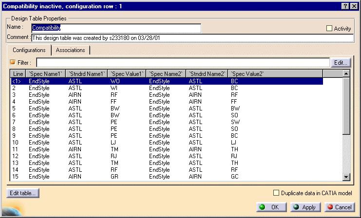
184
Electrical Cableway Routing
 Electrical Cableway Routing Preface Using This Guide What's New? Getting Started Entering the Workbench Placing a Hanger Routing a Loft Through Hangers Placing a Conduit on a Run Saving Documents Updating
Systems Space Reservation
 Systems Space Reservation Preface Using This Guide What's New? Getting Started Enter the Workbench Create an Equipment Reservation Set Correct Working Units and Grid Changing the Current Axis Saving Documents
Piping & Instrumentation Diagrams
 Page 1 Piping & Instrumentation Diagrams Preface Using This Guide What's New? Getting Started Entering the Workbench Setting up Working Units and Grid Placing Components Routing a Piping Line or I & C
Piping & Instrumentation Diagrams
 Piping & Instrumentation Diagrams Preface Using This Guide What's New? Getting Started Entering the Workbench Setting up Working Units and Grid Placing Components Routing a Piping Line or I & C Loop Placing
HVAC Diagrams Preface What's New? Getting Started User Tasks
 HVAC Diagrams Preface Using This Guide What's New? Getting Started Entering the Workbench Setting up Working Units and Grid Placing Components Routing an HVAC Line Placing Components in a Line Repositioning
Compartment and Access
 Compartment and Access Preface Using This Guide What's New? Getting Started Entering the Workbench Set Correct Working Units and Grid Saving Documents User Tasks Creating/Modifying Wall Systems Building
Compartment and Access
 Compartment and Access Page 1 Preface Using This Guide What's New? Getting Started Entering the Workbench Set Correct Working Units and Grid Saving Documents User Tasks Creating/Modifying Wall Systems
Equipment Support Structures
 Equipment Support Structures Overview Conventions What's New? Getting Started Setting Up Your Session Creating a Simple Structural Frame Creating Non-uniform Columns Creating Plates with Openings Bracing
Equipment Support Structures
 Page 1 Equipment Support Structures Preface Using This Guide Where to Find More Information Conventions What's New? Getting Started Setting Up Your Session Creating a Simple Structural Frame Creating Non-uniform
Electrical 3D Design & Documentation
 Electrical 3D Design & Documentation Page 1 Overview Conventions User Tasks Using Electrical 3D Design & Documentation Entering the Electrical Assembly Design Workbench Entering the Electrical Part Design
Tutorial Second Level
 AutoCAD 2018 Tutorial Second Level 3D Modeling Randy H. Shih SDC PUBLICATIONS Better Textbooks. Lower Prices. www.sdcpublications.com Powered by TCPDF (www.tcpdf.org) Visit the following websites to learn
USING THE TRIBALL FOR POSITIONING
 USING THE TRIBALL FOR POSITIONING Although many important positioning tools are available, none are as versatile as the TriBall tool. This TriBall tool offers complete repositioning of many items: Shapes
FreeStyle Shaper & Optimizer
 FreeStyle Shaper & Optimizer Preface What's New Getting Started Basic Tasks Advanced Tasks Workbench Description Customizing Glossary Index Dassault Systèmes 1994-99. All rights reserved. Preface CATIA
SolidWorks 2013 and Engineering Graphics
 SolidWorks 2013 and Engineering Graphics An Integrated Approach Randy H. Shih SDC PUBLICATIONS Schroff Development Corporation Better Textbooks. Lower Prices. www.sdcpublications.com Visit the following
Autodesk Fusion 360: Model. Overview. Modeling techniques in Fusion 360
 Overview Modeling techniques in Fusion 360 Modeling in Fusion 360 is quite a different experience from how you would model in conventional history-based CAD software. Some users have expressed that it
CHAPTER 1 COPYRIGHTED MATERIAL. Getting to Know AutoCAD. Opening a new drawing. Getting familiar with the AutoCAD and AutoCAD LT Graphics windows
 CHAPTER 1 Getting to Know AutoCAD Opening a new drawing Getting familiar with the AutoCAD and AutoCAD LT Graphics windows Modifying the display Displaying and arranging toolbars COPYRIGHTED MATERIAL 2
Appendix B: Creating and Analyzing a Simple Model in Abaqus/CAE
 Getting Started with Abaqus: Interactive Edition Appendix B: Creating and Analyzing a Simple Model in Abaqus/CAE The following section is a basic tutorial for the experienced Abaqus user. It leads you
StickFont Editor v1.01 User Manual. Copyright 2012 NCPlot Software LLC
 StickFont Editor v1.01 User Manual Copyright 2012 NCPlot Software LLC StickFont Editor Manual Table of Contents Welcome... 1 Registering StickFont Editor... 3 Getting Started... 5 Getting Started...
SOLIDWORKS 2016 and Engineering Graphics
 SOLIDWORKS 2016 and Engineering Graphics An Integrated Approach Randy H. Shih SDC PUBLICATIONS Better Textbooks. Lower Prices. www.sdcpublications.com Powered by TCPDF (www.tcpdf.org) Visit the following
Exercise Guide. Published: August MecSoft Corpotation
 VisualCAD Exercise Guide Published: August 2018 MecSoft Corpotation Copyright 1998-2018 VisualCAD 2018 Exercise Guide by Mecsoft Corporation User Notes: Contents 2 Table of Contents About this Guide 4
Preface. Version 5 Release 5. Mold Tooling Design
 Version 5 Release 5 Mold Tooling Design Preface Getting Started Basic Tasks Advanced Tasks Customization Workbench Description Glossary Index Preface The CATIA Version 5 Mold Tooling Design application
Publication Number spse01695
 XpresRoute (tubing) Publication Number spse01695 XpresRoute (tubing) Publication Number spse01695 Proprietary and restricted rights notice This software and related documentation are proprietary to Siemens
Electrical Harness Installation
 Electrical Harness Installation Page 1 Overview Conventions What's New? Getting Started Entering the Workbench Setting Up the Options Creating a Bundle Segment Document Creating Construction Points Defining
2D Tutorial. Project Description: Running VisualAnalysis: Setting Up the Project:
 2D Tutorial Project Description: This project has been set-up to demonstrate the basic features of VisualAnalysis. You will model and analyze the following two-dimensional frame with a curved glue-laminated
TexGraf4 GRAPHICS PROGRAM FOR UTEXAS4. Stephen G. Wright. May Shinoak Software Austin, Texas
 TexGraf4 GRAPHICS PROGRAM FOR UTEXAS4 By Stephen G. Wright May 1999 Shinoak Software Austin, Texas Copyright 1999, 2007 by Stephen G. Wright - All Rights Reserved i TABLE OF CONTENTS Page LIST OF TABLES...v
4. If you are prompted to enable hardware acceleration to improve performance, click
 Exercise 1a: Creating new points ArcGIS 10 Complexity: Beginner Data Requirement: ArcGIS Tutorial Data Setup About creating new points In this exercise, you will use an aerial photograph to create a new
Pipe Networks CHAPTER INTRODUCTION OBJECTIVES
 CHAPTER 11 Pipe Networks INTRODUCTION Pipe networks are integral to a site-design solution. The piping system s complexity can vary from simple culverts to several storm and sanitary networks that service
Publication Number spse01695
 XpresRoute (tubing) Publication Number spse01695 XpresRoute (tubing) Publication Number spse01695 Proprietary and restricted rights notice This software and related documentation are proprietary to Siemens
The Department of Construction Management and Civil Engineering Technology CMCE-1110 Construction Drawings 1 Lecture Introduction to AutoCAD What is
 The Department of Construction Management and Civil Engineering Technology CMCE-1110 Construction Drawings 1 Lecture Introduction to AutoCAD What is AutoCAD? The term CAD (Computer Aided Design /Drafting)
Reset Cursor Tool Clicking on the Reset Cursor tool will clear all map and tool selections and allow tooltips to be displayed.
 SMS Featured Icons: Mapping Toolbar This document includes a brief description of some of the most commonly used tools in the SMS Desktop Software map window toolbar as well as shows you the toolbar shortcuts
Learning the Pro/ENGINEER Interface
 2 Learning the Pro/ENGINEER Interface This chapter introduces the Pro/ENGINEER interface tools: the menus, the dashboards, the selection tools and the viewing controls. As you go through this chapter,
Autodesk Inventor 2019 and Engineering Graphics
 Autodesk Inventor 2019 and Engineering Graphics An Integrated Approach Randy H. Shih SDC PUBLICATIONS Better Textbooks. Lower Prices. www.sdcpublications.com Powered by TCPDF (www.tcpdf.org) Visit the
SILVACO. An Intuitive Front-End to Effective and Efficient Schematic Capture Design INSIDE. Introduction. Concepts of Scholar Schematic Capture
 TCAD Driven CAD A Journal for CAD/CAE Engineers Introduction In our previous publication ("Scholar: An Enhanced Multi-Platform Schematic Capture", Simulation Standard, Vol.10, Number 9, September 1999)
Autodesk Inventor - Basics Tutorial Exercise 1
 Autodesk Inventor - Basics Tutorial Exercise 1 Launch Inventor Professional 2015 1. Start a New part. Depending on how Inventor was installed, using this icon may get you an Inch or Metric file. To be
Electrical Harness Flattening
 Electrical Harness Flattening Overview Conventions What's New? Getting Started Accessing the Electrical Harness Flattening Workbench Defining the Harness Flattening Parameters Extracting Data Flattening
Lesson 1: Creating T- Spline Forms. In Samples section of your Data Panel, browse to: Fusion 101 Training > 03 Sculpt > 03_Sculpting_Introduction.
 3.1: Sculpting Sculpting in Fusion 360 allows for the intuitive freeform creation of organic solid bodies and surfaces by leveraging the T- Splines technology. In the Sculpt Workspace, you can rapidly
Controlling the Drawing Display
 Controlling the Drawing Display In This Chapter 8 AutoCAD provides many ways to display views of your drawing. As you edit your drawing, you can control the drawing display and move quickly to different
Note: To open the new drawing, check the Open new drawing check box.
 Table of Contents Space Allocation Drawings.................................. 3 Set Up Space Allocation Groups.............................. 3 Checking In/Out and Pinning Space Allocations..................
Creating and Analyzing a Simple Model in Abaqus/CAE
 Appendix B: Creating and Analyzing a Simple Model in Abaqus/CAE The following section is a basic tutorial for the experienced Abaqus user. It leads you through the Abaqus/CAE modeling process by visiting
PLAY VIDEO. Fences can be any shape from a simple rectangle to a multisided polygon, even a circle.
 Chapter Eight Groups PLAY VIDEO INTRODUCTION There will be times when you need to perform the same operation on several elements. Although this can be done by repeating the operation for each individual
THE EASTMAN Easicut v2.1
 THE EASTMAN Easicut v2.1 User's Manual This manual must be used in conjunction with the M9000 Machine Instruction and Service manual, Form #E-509-Instructions. 779 Washington St., Buffalo, N.Y. 14203-1396
Module 4A: Creating the 3D Model of Right and Oblique Pyramids
 Inventor (5) Module 4A: 4A- 1 Module 4A: Creating the 3D Model of Right and Oblique Pyramids In Module 4A, we will learn how to create 3D solid models of right-axis and oblique-axis pyramid (regular or
Basic Modeling 1 Tekla Structures 12.0 Basic Training September 19, 2006
 Tekla Structures 12.0 Basic Training September 19, 2006 Copyright 2006 Tekla Corporation Contents Contents 3 1 5 1.1 Start Tekla Structures 6 1.2 Create a New Model BasicModel1 7 1.3 Create Grids 10 1.4
Revit Architecture 2015 Basics
 Revit Architecture 2015 Basics From the Ground Up Elise Moss Authorized Author SDC P U B L I C AT I O N S Better Textbooks. Lower Prices. www.sdcpublications.com Powered by TCPDF (www.tcpdf.org) Visit
SEER-3D: An Introduction
 SEER-3D SEER-3D allows you to open and view part output from many widely-used Computer-Aided Design (CAD) applications, modify the associated data, and import it into SEER for Manufacturing for use in
Lesson 5: Board Design Files
 5 Lesson 5: Board Design Files Learning Objectives In this lesson you will: Use the Mechanical Symbol Editor to create a mechanical board symbol Use the PCB Design Editor to create a master board design
Module 1: Basics of Solids Modeling with SolidWorks
 Module 1: Basics of Solids Modeling with SolidWorks Introduction SolidWorks is the state of the art in computer-aided design (CAD). SolidWorks represents an object in a virtual environment just as it exists
42 Editing MSC Diagrams
 Chapter 42 Editing MSC Diagrams This chapter describes how to create and edit MSCs (Message Sequence Charts). For a reference to the MSC Editor, see chapter 40, Using Diagram Editors. July 2003 Telelogic
Lesson 5 Solid Modeling - Constructive Solid Geometry
 AutoCAD 2000i Tutorial 5-1 Lesson 5 Solid Modeling - Constructive Solid Geometry Understand the Constructive Solid Geometry Concept. Create a Binary Tree. Understand the basic Boolean Operations. Create
3ds Max Cottage Step 1. Always start out by setting up units: We re going with this setup as we will round everything off to one inch.
 3ds Max Cottage Step 1 Always start out by setting up units: We re going with this setup as we will round everything off to one inch. File/Import the CAD drawing Be sure Files of Type is set to all formats
4) Finish the spline here. To complete the spline, double click the last point or select the spline tool again.
 Finish the spline here. To complete the spline, double click the last point or select the spline tool again.") 1) Select the line tool 3) Move the cursor along the X direction (be careful to stay on the X axis alignment so that the line is perpendicular) and click for the second point of the line. Type 0.5 for
1) Select the line tool 3) Move the cursor along the X direction (be careful to stay on the X axis alignment so that the line is perpendicular) and click for the second point of the line. Type 0.5 for
Create a Rubber Duck. This tutorial shows you how to. Create simple surfaces. Rebuild a surface. Edit surface control points. Draw and project curves
 Page 1 of 24 Create a Rubber Duck This exercise focuses on the free form, squishy aspect. Unlike the flashlight model, the exact size and placement of the objects is not critical. The overall form is the
Chapter 4 Feature Design Tree
 4-1 Chapter 4 Feature Design Tree Understand Feature Interactions Use the FeatureManager Design Tree Modify and Update Feature Dimensions Perform History-Based Part Modifications Change the Names of Created
Lesson 1 Parametric Modeling Fundamentals
 1-1 Lesson 1 Parametric Modeling Fundamentals Create Simple Parametric Models. Understand the Basic Parametric Modeling Process. Create and Profile Rough Sketches. Understand the "Shape before size" approach.
User Guide. for. JewelCAD Professional Version 2.0
 User Guide Page 1 of 121 User Guide for JewelCAD Professional Version 2.0-1 - User Guide Page 2 of 121 Table of Content 1. Introduction... 7 1.1. Purpose of this document... 7 2. Launch JewelCAD Professional
Autodesk Inventor Design Exercise 2: F1 Team Challenge Car Developed by Tim Varner Synergis Technologies
 Autodesk Inventor Design Exercise 2: F1 Team Challenge Car Developed by Tim Varner Synergis Technologies Tim Varner - 2004 The Inventor User Interface Command Panel Lists the commands that are currently
Ansoft HFSS Windows Screen Windows. Topics: Side Window. Go Back. Contents. Index
 Modifying Coordinates Entering Data in the Side Windows Modifying Snap To Absolute Relative Each screen in divided up into many windows. These windows can allow you to change the coordinates of the model,
Lesson 2 Constructive Solid Geometry Concept. Parametric Modeling with I-DEAS 2-1
 Lesson 2 Constructive Solid Geometry Concept Parametric Modeling with I-DEAS 2-1 2-2 Parametric Modeling with I-DEAS Introduction In the 1980s, one of the main advancements in Solid Modeling was the development
Introduction to SolidWorks Basics Materials Tech. Wood
 Introduction to SolidWorks Basics Materials Tech. Wood Table of Contents Table of Contents... 1 Book End... 2 Introduction... 2 Learning Intentions... 2 Modelling the Base... 3 Modelling the Front... 10
DMU Space Analysis Version 5 Release 13. DMU Space Analysis
 Page 1 DMU Space Analysis Preface Using This Guide More Information Conventions What's New? Getting Started Setting Up Your Session Measuring Minimum Distances Sectioning Detecting Clashes Measuring Between
Spring 2011 Workshop ESSENTIALS OF 3D MODELING IN RHINOCEROS February 10 th 2011 S.R. Crown Hall Lower Core Computer Lab
 [1] Open Rhinoceros. PART 1 INTRODUCTION [4] Click and hold on the Boundary Lines in where they form a crossing and Drag from TOP RIGHT to BOTTOM LEFT to enable only the PERSPECTIVE VIEW. [2] When the
Autodesk Fusion 360 Training: The Future of Making Things Attendee Guide
 Autodesk Fusion 360 Training: The Future of Making Things Attendee Guide Abstract After completing this workshop, you will have a basic understanding of editing 3D models using Autodesk Fusion 360 TM to
The Rectangular Problem
 C h a p t e r 2 The Rectangular Problem In this chapter, you will cover the following to World Class standards: The tools for simple 2D Computer Aided Drafting (CAD) The Command Line and the Tray The Line
Selective Space Structures Manual
 Selective Space Structures Manual February 2017 CONTENTS 1 Contents 1 Overview and Concept 4 1.1 General Concept........................... 4 1.2 Modules................................ 6 2 The 3S Generator
SETTING UP A. chapter
 1-4283-1960-3_03_Rev2.qxd 5/18/07 8:24 PM Page 1 chapter 3 SETTING UP A DOCUMENT 1. Create a new document. 2. Create master pages. 3. Apply master pages to document pages. 4. Place text and thread text.
Electrical Wire Routing
 Electrical Wire Routing Page 1 Overview Conventions What's New? Getting Started Accessing the Workbench Creating the Bundle Selecting Systems with External Data Routing Wires from External Data User Tasks
QuickTutor. An Introductory SilverScreen Modeling Tutorial. Solid Modeler
 QuickTutor An Introductory SilverScreen Modeling Tutorial Solid Modeler TM Copyright Copyright 2005 by Schroff Development Corporation, Shawnee-Mission, Kansas, United States of America. All rights reserved.
Structure Preliminary Layout
 Page 1 Structure Preliminary Layout Preface Using This Guide Where to Find More Information What's New? Getting Started Setting Up Your Session Defining the Hull Form Setting Up Your Grid Creating Molded
Guide to WB Annotations
 Guide to WB Annotations 04 May 2016 Annotations are a powerful new feature added to Workbench v1.2.0 (Released May 2016) for placing text and symbols within wb_view tabs and windows. They enable generation
Welcome to MicroStation
 Welcome to MicroStation Module Overview This module will help a new user become familiar with the tools and features found in the MicroStation design environment. Module Prerequisites Fundamental knowledge
NC Manufacturing Verification
 NC Manufacturing Verification Overview Conventions What's New? User Tasks Accessing NC Manufacturing Verification Comparing the Machined Stock Part and the Design Part Pick Point Analysis in Video Mode
solidthinking Inspired Tutorials 2009 solidthinking, Inc. for Mac
 solidthinking Inspired Tutorials 2009 solidthinking, Inc. for Mac Table of Contents Quick Start Tutorials 3 Tutorial 11: Simple... Bridge 4 Tutorial 22: Desk... 12 Tutorial 33: Bookcase... 35 2 1 Quick
Wizard PDS. Automated Perimeter Definition System. January Education and Training Center Wizard Date 5/4/2016. Page 1
 PDS Automated Perimeter Definition System January 2016 Page 1 Table of Contents Information Page 3 O Page 32 Operating Procedures Basic Operation Manually Reposition a Truss Snap to Rail Centerline Flip
Osmond Tutorial. First Page / J C Chavez / / Osmond Tutorial
 Osmond Tutorial Draft Version corresponding to Osmond PCB Design Version 1.0b2 November 30, 2002 J C Chavez http://www.swcp.com/~jchavez/osmond.html jchavez@swcp.com First Page / J C Chavez / jchavez@swcp.com
Sheet Metal Overview. Chapter. Chapter Objectives
 Chapter 1 Sheet Metal Overview This chapter describes the terminology, design methods, and fundamental tools used in the design of sheet metal parts. Building upon these foundational elements of design,
ArcView QuickStart Guide. Contents. The ArcView Screen. Elements of an ArcView Project. Creating an ArcView Project. Adding Themes to Views
 ArcView QuickStart Guide Page 1 ArcView QuickStart Guide Contents The ArcView Screen Elements of an ArcView Project Creating an ArcView Project Adding Themes to Views Zoom and Pan Tools Querying Themes
PowerPoint 2016 Building a Presentation
 PowerPoint 2016 Building a Presentation What is PowerPoint? PowerPoint is presentation software that helps users quickly and efficiently create dynamic, professional-looking presentations through the use
Texas School for the Blind and Visually Impaired. Using The Drawing Tools in Microsoft Word 2007 for Tactile Graphic Production
 Texas School for the Blind and Visually Impaired Outreach Programs 1100 West 45 th Street Austin, Texas, 78756 Using The Drawing Tools in Microsoft Word 2007 for Tactile Graphic Production Developed by:
NC Manufacturing Verification
 NC Manufacturing Verification Page 1 Preface Using This Guide Where to Find More Information Conventions What's New? User Tasks Accessing NC Manufacturing Verification Comparing the Machined Stock Part
Shape Sculptor Version 5 Release 13. Shape Sculptor
 Shape Sculptor Page 1 Overview Using This Guide Where to Find More Information What's New? Getting Started Entering the Workbench Importing a Polygonal Mesh Decimating a Polygonal Mesh User Tasks Input
Structural & Thermal Analysis Using the ANSYS Workbench Release 12.1 Environment
 ANSYS Workbench Tutorial Structural & Thermal Analysis Using the ANSYS Workbench Release 12.1 Environment Kent L. Lawrence Mechanical and Aerospace Engineering University of Texas at Arlington SDC PUBLICATIONS
DMU Engineering Analysis Review
 Page 1 DMU Engineering Analysis Review Preface Using This Guide Where to Find More Information Conventions What's New? Getting Started Inserting a CATAnalysis Document Using DMU Space Analysis From CATAnalysis
SiphoniTec. User s Guide
 SiphoniTec A Siphonic Roof Drainage Design Utility The Level Approach to Roof Drainage User s Guide Release 2.0 RAINWATER MANAGEMENT SOLUTIONS 1260 West Riverside Drive Salem, Virginia 24153 Telephone:
DuctworkPro. User Guide
 DuctworkPro for AutoCAD User Guide Version 2.0, March. 2004 Copyright 2004, Randall C. Wilkinson By Randall C. Wilkinson Freeware Version Users: This document describes the Professional Version of Ductwork.
Multiframe Windows Version 16. User Manual
 Multiframe Windows Version 16 User Manual Bentley Systems, Incorporated 2013 License & Copyright Multiframe Program & User Manual 2013 Bentley Systems, Incorporated iii Table of Contents License & Copyright...
Beaumont Middle School Design Project April May 2014 Carl Lee and Craig Schroeder
 Beaumont Middle School Design Project April May 2014 Carl Lee and Craig Schroeder 1 2 SketchUp 1. SketchUp is free, and you can download it from the website www.sketchup.com. For some K12 use, see www.sketchup.com/3dfor/k12-education.
FreeStyle Shaper Optimizer & Profiler
 FreeStyle Shaper Optimizer & Profiler Page 1 Preface Using This Guide More Information What's New? Getting Started Starting the FreeStyle Workbench Creating a First Surface Editing the Surface Creating
Google SketchUp. and SketchUp Pro 7. The book you need to succeed! CD-ROM Included! Kelly L. Murdock. Master SketchUp Pro 7 s tools and features
 CD-ROM Included! Free version of Google SketchUp 7 Trial version of Google SketchUp Pro 7 Chapter example files from the book Kelly L. Murdock Google SketchUp and SketchUp Pro 7 Master SketchUp Pro 7 s
1.1: Introduction to Fusion 360
 .: Introduction to Fusion 360 Fusion 360 is a cloud- based CAD/CAM tool for collaborative product development. The tools in Fusion enable exploration and iteration on product ideas and collaboration within
Design a Simple Fan in 123D Design
 Design a Simple Fan in 123D Design Learn to use 123D Design to make and print this simple fan. 123D Design is a free, powerful, yet simple 3D creation and editing tool. It allows you to design and build
Designer Reference 1
 Designer Reference 1 Table of Contents USE OF THE DESIGNER...4 KEYBOARD SHORTCUTS...5 Shortcuts...5 Keyboard Hints...5 MENUS...7 File Menu...7 Edit Menu...8 Favorites Menu...9 Document Menu...10 Item Menu...12
for ArcSketch Version 1.1 ArcSketch is a sample extension to ArcGIS. It works with ArcGIS 9.1
 ArcSketch User Guide for ArcSketch Version 1.1 ArcSketch is a sample extension to ArcGIS. It works with ArcGIS 9.1 ArcSketch allows the user to quickly create, or sketch, features in ArcMap using easy-to-use
A Guide to Autodesk Maya 2015
 A Guide to Autodesk Maya 2015 Written by Mitchell Youngerman Table of Contents Layout of Toolbars...pg 1 Creating Objects...pg 2 Selecting & Deselecting Objects...pg 3 Changing Perspective... pg 4 Transforming
A Step-by-step guide to creating a Professional PowerPoint Presentation
 Quick introduction to Microsoft PowerPoint A Step-by-step guide to creating a Professional PowerPoint Presentation Created by Cruse Control creative services Tel +44 (0) 1923 842 295 training@crusecontrol.com
Quick Start Guide. ARIS Architect. Version 9.8 Service Release 2
 ARIS Architect Version 9.8 Service Release 2 October 2015 This document applies to ARIS Version 9.8 and to all subsequent releases. Specifications contained herein are subject to change and these changes
Mn/DOT MnCMAT Crash Analysis Application Help
 Mn/DOT MnCMAT Crash Analysis Application Contents Login... 5 User Login Dialog... 5 Login... 5 Request Access Dialog... 5 Forgotten Password Dialog... 6 Create/Open Project... 7 Create/Open Project Dialog...
Mechanical Design V5R19 Update
 CATIA V5 Training Foils Mechanical Design V5R19 Update Version 5 Release 19 August 2008 EDU_CAT_EN_MD2_UF_V5R19 1 About this course Objectives of the course Upon completion of this course you will be able
Defining Board Regions and Bending Lines
 Defining Board Regions and Bending Lines Old Content - visit altium.com/documentation Modified by on 29-Nov-2016 Related Videos Bending Lines Layer Stack Regions A Board Region is the term used to describe
OrgPublisher Advanced Box Layout Editor
 OrgPublisher Advanced Box Layout Editor OrgPublisher Table of Contents Table of Contents... 3 Using the... 3 Arranging Chart Box Sections... 3 Sizing the Chart Box Section... 4 Moving, Deleting, or Resizing
XPEL DAP SUPPORT. DAP Tool List & Overview DESCRIPTION ICON/TOOL (SHORTCUT)
") Pointer (S) Left-click on individual entities to add them to the current selection (selected entities will turn red). If the entity selected is a member of a group, the entire group will be added to the
Pointer (S) Left-click on individual entities to add them to the current selection (selected entities will turn red). If the entity selected is a member of a group, the entire group will be added to the