Brief Introduction to MasterCAM X4
|
|
|
- Joshua Anderson
- 5 years ago
- Views:
Transcription
1 Brief Introduction to MasterCAM X4 Fall 2013 Meung J Kim, Ph.D., Professor Department of Mechanical Engineering College of Engineering and Engineering Technology Northern Illinois University DeKalb, IL
2 Preliminaries C-Plane: flat construction plane that can be used for sketching T-Plane: flat machinable plane MMB to rotate the model in graphics window Alt + MMB (middle mouse button) to pan Selecting WCS and changing Z level Hint appears at top of graphics window If some entities cannot be selected sometimes in graphics window (i.e., bug), use Unhide/All to show all entities and select. For Chain, the line segments in the curve must be tangent. If the curve is closed, use Loop. Settings o Configurations > see or change Units o Colors > Graphics background color > change it if needed


3 I. Sketching and Editing T/Cplane and WCS (Tool / Construction Plane and World Coordinate System) 1. Construction plane is the plane where any geometry can be constructed and Tool plane is the plane perpendicular to tool axis for machining. 2. The default level of T/Cplane is at Z=0.0 with x-y axes on the plane aligned with WCS:TOP. Any sketches are added on this plane. 3. Change the WCS and Z value to change the sketch plane. 4. Change the view to isometric view by right clicking on the graphics window and selecting it. 5. Any sketched entities can be selected and deleted. Sketching 1. Sketching menu is shown below. 2. The sketch menu of Line is shown below. 3. Starting point can be picked on the graphics window. Alternatively, entered above. 4. Further, Fast Point can be used to enter x,y,z values quickly. 5. Enter or select appropriate values and options. 6. Pick the second point and further change any values/options > Apply or OK Analyze
 is shown below. Use ESC to cancel. 2. The following shows Dynamic Translate dialog.")
4 7. This menu can be used to analyze and modify properties of entities. Sketch a circle > OK 8. Analyze > Entity Properties > pick the circle > change any properties > OK Transform 1. XForm menu (XForm, Translate, Rotate, Mirror, Scale, Translate 3D, Offset, etc.) is shown below. Use ESC to cancel. 2. The following shows Dynamic Translate dialog. Pick any to move > End Selection button > use either incremental Delta or From/To to specify the distance. 3. For Dynamic Transform, pick any entities to transform > End Selection > gnomon triad appears > anchor it to a starting position > move mouse over lower end of any axis to move and click, otherwise, move over higher end of the axis to rotate and click > the attached gnomon can be move or rotated to another position > click at a new position > [user can cancel by successive ESC any time] > OK
 > Cplane = Front (WCS) 4.")
 > OK 6.")
5 Surface 1. Create > Surface > Flat boundary > pick closed boundary like a circle or polygon 2. Alt + G > check both Active and Visible grid > OK 3. Isometric (WCS) > Cplane = Front (WCS) 4. Create arc three points > pick any three points to sketch the arc > OK 5. Xform translate > pick the arc > End selection > check Join > enter a value for Z (make it long) > OK 6. Xform translate > pick either arc > End selection > check Copy > enter a value for Z and Y to copy it below in the middle > OK
 and then the copied arc (see")


 > Style = Ruled (see right) 11. 3D > Z = 0.")

6 7. Create > Surface > Net > pick all four joined lines in sequence (directions don t matter) and then the copied arc (see the second above) a. Choose Across for Style (the last arc is not included. See the third) b. Choose Average (average is used between two entities. See the last) 8. Change to 2D for sketching 9. Circle a. Sketch a circle b. Change Z-value to 10 > sketch another circle c. Change Z-value to -8 > sketch another circle > OK 10. Create/Surface > Rules/Lofted > pick three circles in sequence and make sure the directions are all same > Style = Lofted (see above middle) > Style = Ruled (see right) 11. 3D > Z = 0.0 > Sketch a closed figure as 12. Create/Surface > Revolved a. Chain > pick a point on the figure > OK b. Angle = 180 c. Select the horizontal line for the axis of rotation (see above) 13. Front (WCS) > sketch a spline > OK 14. Isometric (WCS) > sketch a circle at an end point of spline


7 15. Create/Surface > Swept a. Across contour > pick the circle > OK b. Along the curve > pick the spline > OK
 with horizontal length of 4")

8 16. Starting with 2D/3D Contours Contour 1. Machine Type > Mill / Default 2. Now, user needs toolpaths. 3. Line > sketch lines starting at (1,1,0) with horizontal length of 4 and the rest of lines have length of Stock Setup > All Entities > add a little more space for each if needed as shown below > OK. Note that Stock Origin is the position at top surface of stock and the depth is given by Z value. 5. Toolpaths > Contour > enter a name > selection dialog appears as


9 6. Select the line and choose the direction 7. Toolpath dialog appears 8. Toolpath Type = Contour. Other toolpath can be chosen here Also, see Chain geometry if needed.

 = 25 [this cannot be zero] and")

10 9. Tool > enter tool diameter = 0.25 and other parameters as below, otherwise, use the tool library. 10. Holder = no holder display 11. Cut Parameters > Depth Cuts = check Depth cuts / Max rough step = Linking Parameters: Depth = -0.5 and change others as needed > OK 13. Click the tool in OM > change any parameters as needed > see Type > Parameters tab > Rough XY step (%) = 25 [this cannot be zero] and Rough Z step = 0.25 > OK 14. Right click Toolpath in OM (Operations Manager) > adjust the speed and play, see below > OK 15. Right click the graphics window > WCS:TOP > see the toolpath above right. 16. The toolpath display can be toggled on/off by 17. Observation a. Tool moves to retract plane above the approach point and plunges to feed plane, then plunge cut first and follows the toolpath.
 > OK 19. Play the toolpath simulation and see it.")
11 b. Approach/Exit movements are along tangent arcs. c. Toolpath compensation is to left to the toolpath. 18. Click Parameters in OM > Cut Parameters > change the tool compensation direction to Right > (It can be turned off if not needed) > OK 19. Play the toolpath simulation and see it. Observe the Approach/Exit movements. 20. Back to Parameters in OM > Lead In/Out > see the approach/exit parameters as 21. Also, see Linking Parameters as


12 Pocket 1. Using same as above for most, sketch a similar pocket shape as below 2. Toolpaths > Pocket a. Choose Loop b. Pick the contour > switch the direction if necessary c. Linking Parameters > Depth = > OK Facing 1. Use same contour for face milling 2. Toolpaths > Face a. Choose Loop b. Pick the contour > switch the direction if necessary c. Linking Parameters > Depth = > OK

, Dynamic Transform 2.")

13 3. Note that face milling uses two opposite boundaries to cover the area between them. Also, the tool moves out of the boundary. Contour (3D) 1. Sketch as below using WCS (TOP, FRONT, RIGHT), Dynamic Transform 2. Stock Setup 3. Toolpaths > Contour a. Loop > pick the contour > switch the direction if necessary b. Toolpath Type = Contour c. Tool = ¼ Flat End Mill d. Linking Parameters > Depth = > OK

 > View by Solid Face > pick the front face > accept the orientation h. Sketch a rectangle with round corners as 2.")
14 Tplanes (3D) 1. Create Block a. Fast Point > enter 0,0,0 > CR b. Check Solids c. Enter 5, 4, and 3 for size > OK d. Right click on graphics window > Isometric View e. Zoom Fit or scroll up/down and alt + move to position the block f. Polygon > Fast Point > enter 2.5,2,3 > CR > check Corner and enter 5 for number of sides as below > OK g. Gview (at bottom status bar) > View by Solid Face > pick the front face > accept the orientation h. Sketch a rectangle with round corners as 2. Toolpaths > Drill a. Pick all five corners of pentagon at top > OK b. Tool > Select library tool > ¼ Drill > OK c. Linking Parameters > enter as below > OK


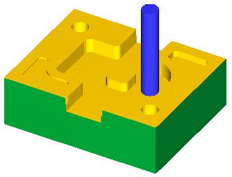
15 3. Stock Setup > All Entities > OK 4. Play and see the drilling as 5. Gview > View by solid surface > pick the front face > OK 6. Sketch a rectangle with corner rounds 7. Toolpaths > Pocket a. Chain > pick the front rectangle > OK b. Linking Parameters > Depth = -0.5 > OK c. Play and see above right 8. Gview > View by solid face > pick the right face > OK 9. Sketch another rectangle on rightside face 10. Toolpaths > Pocket a. Chain > pick the front rectangle > OK b. Linking Parameters > Depth = 4.5 > OK 11. Select Toolpath Group-1 in OM > Verify selected operation > play and see as


16 12. See also the toolpath with point-to-point (PTP) motion in light yellow color and the machining in light blue. 13. Parameters of first Pocket in OM > Entry Motion > Off > OK > Back plot 14. Post a. Check NC file / Edit / Ask > OK b. No c. Enter a name for NC file > CR > NC file appears as below > read and understand each line. Observation: A-90 changes the Tplane with a local coordinates.

 > see also option of Across/Along > Max")

17 2D High Speed This has several toolpath type as shown below. 1. Toolpaths > 2D High Speed a. Pick the first contour > change direction if needed > pick the second contour > OK b. Toolpath Type = Blend Mill c. Tool = 0.25 flat end mill d. Cut Parameters > Cutting method = Zigzag (see also other options) > see also option of Across/Along > Max stepover = 0.1 e. Linking Parameters > Depth = > OK f. Right click Toolpath in OM > play and see g. Parameters in OM h. Change Toolpath Type = Peel Mill i. Rounding radius = 0.25, Stepover = 0.25 j. Linking Parameters > Depth = > OK k. Right click Toolpath in OM > play and see


18 l. Delete the contour and sketch two others as below (use Line, Offset, and Fillet) m. Parameters in OM n. Change Toolpath Type = Core Mill o. Geometry in OM > right click the collector > Add Chains > add first chain > Add Chains > add the second one p. Right click Toolpath in OM > play and see q. Parameters in OM r. Change Toolpath Type = Area Mill s. Right click Toolpath in OM > play and see t. Parameters in OM u. Change Toolpath Type = Dynamic Mill v. Right click Toolpath in OM > play and see

19


20 17. Starting with 3D Model Case 1. Sketch 2D shape and extrude features. 1. Alt + g for Grid > check Acitve grid and Visible grid > OK 2. Solids > Extrude a. Loop > pick a line on inner loop of outline > make sure the loop direction is CW > OK b. Cut Body > Extend by specified distance/distance = 0.25 > OK c. Repeat this for obround with depth = 0.5 > OK d. Repeat it by selecting four holes in CW with Extend thru all > OK 3. Machine Type > Mill > Default 4. Expand the Generic Mill in OM > Stock Setup a. Select corners > select two diagonal corners with some materials on sides b. Enter the depth = 1 > OK 5. Add another sketch around the workpiece 6. Toolpaths > 2D High Speed a. Pick the loop on workpiece and the loop of part outline > OK b. Tool Type = Core Mill c. Tool > select one inch tool d. Linking Parameters > Depth = -1.1 > OK e. Verify> choose Turbo 7. Toolpaths > Surface Rough > Pocket a. Pick the surface of part at top b. Select the 1/2 inch tool > OK c. Verify > choose Turbo

21 8. Toolpaths > Drill a. Pick all four holes at centers > OK b. Toolpath Type > Drill c. Tool > Filter > select the drill tool > OK > select 1/8 Drill > OK d. Break Through > check Break through > Break through amount = 0.1 e. Linking Parameters > Depth = -1 > OK 9. Select Toolpath Group-1 in OM > choose Tool > Verify Case 2. Based on a MasterCam X example, produce a revolved cut on a block by Surface High Speed (i.e., roughing), Surface Finish, Surface Finish Leftover. Then, create a word CAM by Pocket on the top surface and project it onto the bottom of the previous cut. Also, learn to correct tool handle interference by Surface Finish Pencil. Note that Surface High Speed milling can find all surfaces and machine them. However, the tool must be small enough to fit the surfaces to machine them. Otherwise, it skips any unfit surfaces. Further, if the step depth is greater than the depth of any surface, it also skips.


22 1. Alt + G for Grid > check Acitve grid and Visible grid > OK 2. Create Line End Point > sketch a vertical line from the origin with length 5 > OK 3. Create Line Parallel > pick the line > click a point on the right > enter the distance 2 > CR > pick the same first line > click a point at distance 2 to right > OK 4. Create Line End Point > sketch a horizontal line at bottom and at top, and an inclined line with angle 290 as 5. Create Arc Tangent > Tangent Point > enter radius 2, pick the inclined line 1 and the end point 2 of bottom horizontal line > click the part to keep at 3 > OK 6. Trim/Break/Extend > Trim 1 Entity > click the inclined line to trim and click the line to trim > OK 7. Delete entities > pick both vertical lines on the right > End Selection 8. Fillet > enter the radius and pick both lines at upper right corner > both lines at lower right corner > OK 9. Create > Letters > enter CAM > select True Type > Arial/Bold/12 > OK > pick a starting point > ESC (done)
 11. Clear Colors (2 nd of toolbar) 12. Shift + pick a line in the loop > Xform Mirror > check X-axis in dialog > OK 13.")
 > OK > enter the angle 180 > pick the line at center for rotation axis >")
 > Done Selection > refresh the screen > repeat this to delete another line at same position (see above right) 17. Top (WCS) 18.")
 > pick a point on the curve along the edge of revolved surface (it s a loop showing only an")
23 10. Click a lower left corner, hold down LMB, drag to another corner, click to select the text just created > Xform Translate > check Move > From/To > pick starting and ending point to translate > OK (may repeat to place it at proper position) 11. Clear Colors (2 nd of toolbar) 12. Shift + pick a line in the loop > Xform Mirror > check X-axis in dialog > OK 13. Clear Colors 14. Isometric View > Fit > alt + g > uncheck both Active and Visible grid > OK 15. Create / Surface / Revolved > pick a line on right side and then the line at center (to complete a loop) > OK > enter the angle 180 > pick the line at center for rotation axis > choose correct side by > OK 16. Delete entities > pick the line at center (two of them) > Done Selection > refresh the screen > repeat this to delete another line at same position (see above right) 17. Top (WCS) 18. Create Rectangle > click Anchor to Center and Create Surface > sketch a rectangle starting from the center > OK 19. Isometric (WCS) > Fit > pan the geometry by alt + MMB 20. Create > Surface > Trim > To Curves > pick the plane > Done Selection > Loop (or Chain) > pick a point on the curve along the edge of revolved surface (it s a loop showing only an arrow on top of ending arrow) > Done Selection > pick a point on plane to keep and then pick another point > OK 21. Expand Generic Mill in Operations Manager (OM) a. Stock setup > Bounding box > increase the depth by 1 > OK > OK 22. Toolpaths > Surface High Speed
 f. Linking Parameters (accept defaults) g. OK (dialog) 23.")


 as below > OK c. Select library > 1/2 Ball End Mill #256 d. Surface parameters > see e. Finish contour parameters > see > OK 26.")
24 a. Enter a name > OK > All > OK > Done Selection > OK b. Toopath Type = Area Clearance c. Tool > Select library tool > #294: 1 inch Bull End Mill with Cor. Rad > OK d. Holder > Open Library > C40.holder > OK > C2C e. Cut Parameters (accept defaults) f. Linking Parameters (accept defaults) g. OK (dialog) 23. Click Back plot selected operations in the menu or OM > Play 24. Verify selected operations or right click Toolpath in OM > play and see above. a. User can select Tool Holder to display. b. Turbo for fast simulation. c. Also, control the simulation speed bar as needed. 25. Toolpaths > Surface Finish > Contour a. All > OK > Done Selection b. Containment in Toolpath/surface selection > try to pick a point on looped edge of revolved surface. If no edge can be selected, then, try Unhide some > All > OK > Done Selection > Loop or Chain option > retry to pick the loop (there must be only one arrow that overlaps the ending arrow) as below > OK c. Select library > 1/2 Ball End Mill #256 d. Surface parameters > see e. Finish contour parameters > see > OK 26. Click Only display selected toolpath in OM > see the toolpath (above right) 27. Select Toolpath Group-1 in OM > Verify selected operations a. Select Simulate tool and holder > Play b. See the interference of handle with workpiece
 > play and see (no good) f.")

 35. Toolpaths > Pocket a.")
25 28. Toolpaths > Surface Finish > Leftover a. All > OK > Done Selection b. Select library > Filter > select only Ball End > OK > 1/4 Ball End Mill #252 c. Surface parameters > see d. Finish leftover parameters > see > OK e. Verify selected operations > (if no material is left over, an error message appears) > play and see (no good) f. Select Toolpath Group-1 in OM > Verify selected operations > play and see more handle interference with stock (will be fixed later) (above right) 29. Click the insert arrow in OM > move it up 30. Select each operation in OM > click Toggle display on selected operation to turn off > repeat for all to turn off 31. Create > Surface > Offset > pick all revolved surfaces > Done Selection > enter offset 0.25 > choose the offset side to outside > OK 32. Clear Colors 33. Top (WCS) 34. Create Rectangular Shapes > Obround > select obround for shape > pick the center point in graphics window > click center for Anchor > sketch the obround > OK (see below left) 35. Toolpaths > Pocket a. Window > capture the obround and text by Window menu (see below middle) > pick a point on obround edge for approximate starting point > OK b. Tool > 1/8 Ball Mill #249 > accept default for all others c. Choose a handle like C4C d. Linking Parameters > Depth = > OK e. Verify selected toolpath > play and see below right


 operation and Surface Finish Project in OM (only last one is")
26 36. Toolpaths > Surface Finish > Project a. Pick both offset surfaces at bottom > Done Selection > OK b. Tool > 1/8 Ball Mill > accept default for all others c. Finish project parameter > Projection type = NCI > check Pocket operation > OK d. Backplot selected operation > OK e. Select Toolpath Group-1 in OM > Verify selected operations > play f. There is interference of tool handle with workpiece that must be fixed. 37. Right click and hold down Pocket operation in OM, drag down a little, and release > Copy after 38. Click Parameters of copied operation a. Tool > select tool #242 from the library b. Cut parameters > Pocket type = Remachining c. OK 39. Regerate all dirty operations in OM 40. Ctrl + pick Pocket (Standard) operation and Surface Finish Project in OM (only last one is highlighted) to select multiple operations > Verify selected toolpaths > see the toolpath simulation 41. Toolpaths > Surface Finish > Pencil a. Pick both offset surfaces > OK b. Tool > 1/8 Ball Mill > accept default for all others > OK 42. [Fixing handle interference] Select Surface Finish Leftover in OM

27 a. Alt + C b. Select CheckHolder.dll > enter the Holder clearance of 0.05 and defaults for all others c. Perform test > if there is interference in the test result, click Modify source operation d. Toolpath Group-1 in OM > Verify selected operations > select Stop after each operation or Stop after collision > play to find out problem operations e. Repeat checking and modifying the tool holder length for all operations where tool interferes with workpiece. f. Run the verification of the toolpath group and see it (above right) 43. Turn off Quick verify in Back plot selected toolpath and see the cutter location (CL) points. Case Create Block > enter width=5, depth=4, and height=1 and then starting position X=0, Y=0, Z=0 > OK 2. Create Cone > enter the base radius=1, the top radius=1.5, and the height=1 > Fast Point > enter the position at bottom center of the block as 2.5,2,0 > OK 3. Stock Setup in OM > enter as below 4. Toolpaths > Surface Rough > Parallel a. Cavity > OK > enter NC name > OK > pick the cone > End Selection > OK (toolpath/surface selection) > OK (Surface rough parameters) b. Click the tool in OM > enter sizes as


 > OK")

28 c. Geometry > pick the cone > OK d. Parameters > just use the defaults e. Right click Toolpath > play and see the result 5. Toolpaths > Surface Rough > Radial a. Cavity > OK > enter NC name > OK > pick the cone > End Selection > OK (toolpath/surface selection) > OK (Surface rough parameters) b. Pick the bottom center of cone as the radial point c. Right click Toolpath > play and see the result 6. Toolpaths > Surface Rough > Pocket

 > OK (Surface rough parameters) > OK (Flowline")
29 a. Pick the cone > End Selection > OK (toolpath/surface selection) > OK (Surface rough parameters) b. Pick the bottom center of cone as the radial point c. Right click Toolpath > play and see the result 7. Toolpaths > Surface Rough > Flowline a. Pick the cone > End Selection > OK (toolpath/surface selection) > OK (Surface rough parameters) > OK (Flowline data) [the cone surface becomes flowline]. b. Right click Toolpath > play and see the result

![The following shows the imported model created in Pro/E [the file extension must be *.prt]. 3.](/docs-images/82/84954779/images/30-1.jpg "Alt + G and check both Active and Visible grid 4. Isometric (WCS) > rotate it a little and see 5.")

 to display the translation or rotation marks as above")
30 18. Starting with External Model Case 1. Pro/E Part File 1. Create a model in Pro/E or any CAD software. Alternatively, the model can be created within MasterCAM. 2. Open the file that was created in other CAD program. The following shows the imported model created in Pro/E [the file extension must be *.prt]. 3. Alt + G and check both Active and Visible grid 4. Isometric (WCS) > rotate it a little and see 5. The milling operation requires the z-axis aligned to the tool axis. In this model, the z-axis was not aligned with z-axis. a. XForm > Dynamic XForm c. All > OK > End Selection d. Anchor the gnomon axes at lower left corner e. Choose Move option. f. Move the mouse over the gnomon axes (below or above axis name) to display the translation or rotation marks as above g. Right (WCS) h. Anchor it at top left corner i. Click the Y or Z axis name for rotation > rotate place the model by 90 degrees CCW j. Isometric (WCS)

 > see it n. OK 8.")

31 k. Click to select translation in X-axis > move the point to X = 1 position l. Click select translation in Y-axis > move the point to Y = 1 position m. Top (WCS) > see it n. OK 8. Isometric (WCS) > Fit and zoom in/out with MMB 9. Alt + G > turn off the grid 10. Expand Default Generic Mill in OM > Stock setup a. All Entities > OK


32 11. Clear Colors 12. Toolpaths > FBM Mill (feature-based milling) a. Click OK to accept the values in the dialog as it is (see below)


 in OM and right")
33 b. Enter a new NC name > OK c. The automatically generated processes appear in OM along with the toolpaths generated as d. Move the mouse over Toolpath for 2D High Speed (2D Core Mill) in OM and right click to bring Verify selected toolpath dialog as
 and see the simulation.")


34 e. Adjust the speed control and click Play (don t see moving?, then probably too slow) and see the simulation. The above right figure shows the completed part. f. Right click the other process and play the simulation to see the following. g. Out of two processes that were generated automatically, the user may keep either one or both and can modify them further. 13. Add FBM Drill as before from Toolpaths menu > OK (accept all defaults) a. Now, the Operation Manager (OM)/Toolpaths appear as


35 b. Play both sequences of Drill/Counterbore and Peck Drill as before. c. Select FBM Drill in OM > click Verify selected operations menu d. Play the FBM Drill operation and see. e. Click the drill tool in OM to bring up the tool as f. See also the Type tab as

36 g. Select Machine Group-1 in OM just created > click Verify selected operations > Play and see 14. Select 2D High Speed (2D Core Mill) in OM 15. Only display selected toolpath 16. Click Parameters in OM a. Cut Parameters Depth Cuts > check Depth cuts > Max rough step = 0.5 Transitions > Entry method > check Profile ramp > Plunge angle = 45 Linking Parameters > Home / Reference. Points > check both Approach and Retract and enter (0,0,2) for both OK a. Backplot selected operation > turn off Quick verify > see the toolpath cutter location (CL) points. Observe the helical or profile ramp motion has numerous points that slow down the tool motion (see below). b. Verify selected operation > play and see > OK


37 Case 2. IGES File 1. Save a part file in CAD software as *.iges (or *.igs) file 2. Open the file in MaxterCam 3. Dynamic Xform > rotate and translate so that the lower left corner is at (1,1,-2) 4. Expand Generic Mill in OM > Stock setup a. All Entities b. Enter as 5. Using View > Viewport > several views can be manipulated as

 c.")

38 6. Toolpaths > Facing a. Select library tool > Filter > select only End Mill > OK > choose 1 inch with no corner radius (#243) b. Cut Parameters > Across overlap = 50 (%) c. Linking parameters > Depth = -0.4 > OK d. Back plot in OM e. Verify in OM 7. Toolpaths > Surface High Speed a. All > OK > Done Selection b. Tool > Select 1/2 Flat End Mill c. Cut Parameters > Step down = 0.25 d. Transition > check Profile ramp and Plunge angle = 45

39 e. OK 8. Toolpath Group-1 in OM > Verify > the shallow pocket was not captured 9. Parameters of Surface High Speed > select 1/4 Flat End Mill > OK > Verify and see the above right. Also, the step depth must be less than the pocket depth to capture it in machining. With smaller step depth, use Steep/Shallow > check Use Z Depths and Detect limits. Observation: Using a single Surface High Speed operation may be too costly with small step depth. Use several Surface High Speed operations. 10. For drilling, create points at centers of hole. Analyze > Dynamic a. Click an arc > move the mouse to place the position arrow at one end as below and get y-position b. Move the arrow to top of arc and get x-position c. Repeat this for center position of the other arc 11. Z = -0.3 (z-plane level at just above model) 12. Create > Point > Fast Point > enter the first center > CR > enter the second center > CR 13. Toolpaths > Drill a. Select both centers of hole > OK b. Tool > select 1/2 drill c. Linking Parameters > Incremental and Depth = -1.9 d. OK 14. Select Toolpath Group-1 in OM > Verify

40


.")

41 Problems Problem. 1 Import the dxf file for key-ring in the textbook and contour mill with the one-inch thick workpiece. Use 0.1 diameter tool with left tool compensation. Solution: Problem. 2 Sketch the contour in Example 2 in the textbook and add a point for SP (0,0,0). Create the one inch thick workpiece with some extra materials around. Simulate contour milling with SP as Home/Retract Points. Soultion:

42 Problem. 3 steps. Sketch the shape similarly and machine as shown below. Describe the
Introduction to MasterCAM X4,7
 Introduction to MasterCAM X4,7 Spring 2014 By Meung J. Kim, Ph.D., Professor Department of Mechanical Engineering Northern Illinois University 1 Preliminaries C-Plane: flat Construction plane that can
Jewelry Box Lid. A. Sketch Lid Circle. Step 1. If necessary start a new Mastercam file, click FILE Menu > New. Fig. 3
 Mastercam X9 Chapter 39 Jewelry Box Lid A. Sketch Lid Circle. Step 1. If necessary start a new Mastercam file, click FILE Menu > New. Step 2. Click CREATE Menu > Arc > Circle Center Point. Step 3. Key-in
Belt Buckle A. Create Rectangle. Step 1. If necessary start a new Mastercam file, click New
 Mastercam 2017 Chapter 35 Belt Buckle A. Create Rectangle. Step 1. If necessary start a new Mastercam file, click New (Ctrl-N) on the Quick Access Toolbar QAT. Step 2. On the Wireframe tab click Rectangle.
Mastercam X9 for SOLIDWORKS
 Chapter 21 CO2 Shell Car Mastercam X9 for SOLIDWORKS A. Enable Mastercam for SOLIDWORKS. Step 1. If necessary, turn on Mastercam for SOLIDWORKS, click the flyout of Options on the Standard toolbar and
Chapter 39. Mastercam Jewelry Box Tray. A. Sketch Tray Circle. B. Twin Edge Point Circles. Mastercam 2017 Tray Jewelry Box Page 39-1
 Mastercam 2017 Chapter 39 A. Sketch Tray Circle. Jewelry Box Tray Step 1. If necessary start a new Mastercam file, click New (Ctrl-N) on the Quick Access Toolbar QAT. Step 2. On the Wireframe tab click
Mill Level 1 Training Tutorial
 To order more books: Call 1-800-529-5517 or Visit www.inhousesolutions.com or Contact your Mastercam dealer Mastercam X 5 Copyright: 1998-2010 In-House Solutions Inc. All rights reserved Software: Mastercam
TRAINING GUIDE MILL-LESSON-FBM-1 FBM MILL AND FBM DRILL
 TRAINING GUIDE MILL-LESSON-FBM-1 FBM MILL AND FBM DRILL Mastercam Training Guide Objectives Previously in Mill-Lesson-6 and Mill-Lesson-7 geometry was created and machined using standard Mastercam methods.
4 & 5 Axis Mill Training Tutorials. To order more books: Call or Visit or Contact your Mastercam Dealer
 4 & 5 Axis Mill Training Tutorials To order more books: Call 1-800-529-5517 or Visit www.inhousesolutions.com or Contact your Mastercam Dealer Mastercam X Training Tutorials 4 & 5 Axis Mill Applications
Penny Hockey SOLIDWORKS 17 to Mastercam 2017 A. Open File in Mastercam Step 1. If necessary, save your BASE file in SOLIDWORKS.
 Mastercam 2017 Chapter 22 Chapter 7 Penny Hockey SOLIDWORKS 17 to Mastercam 2017 A. Open File in Mastercam 2017. Step 1. If necessary, save your BASE file in SOLIDWORKS. Step 2. In Mastercam 2017, click
Fig. 2 Mastercam 2020 Spinning Top SW 19 to MCam20 TOOLPATHS Page 13-1
 Mastercam 2020 Chapter 13 Spinning Top SOLIDWORKS 19 to Mastercam 2020 A. Open File in Mastercam 2020. Step 1. If necessary, save your Handle and Flywheel parts file in SOLIDWORKS. Step 2. In Mastercam
Chapter 36. Mastercam Jewelry Box Fixture. A. Sketch Fixture Rectangle. Step 1. If necessary start a new Mastercam file, click New
 Mastercam 2017 Chapter 36 Jewelry Box Fixture A. Sketch Fixture Rectangle. Step 1. If necessary start a new Mastercam file, click New (Ctrl-N) on the Quick Access Toolbar QAT. Step 2. On the Wireframe
MASTERCAM DYNAMIC MILLING TUTORIAL. June 2018
 MASTERCAM DYNAMIC MILLING TUTORIAL June 2018 MASTERCAM DYNAMIC MILLING TUTORIAL June 2018 2018 CNC Software, Inc. All rights reserved. Software: Mastercam 2019 Terms of Use Use of this document is subject
Cudacountry Radial. Fig. 2. Point. Fig. 4. Mastercam 2017 Cudacountry Radial Page 19-1
 Mastercam 2017 Chapter 19 Cudacountry Radial A. Create Rectangle. Step 1. If necessary start a new Mastercam file, click New QAT. (Ctrl-N) on the Quick Access Toolbar Step 2. On the Wireframe tab click
TOOLPATHS TRAINING GUIDE. Sample. Distribution. not for MILL-LESSON-4-TOOLPATHS DRILL AND CONTOUR
 TOOLPATHS TRAINING GUIDE MILL-LESSON-4-TOOLPATHS DRILL AND CONTOUR Mill-Lesson-4 Objectives You will generate a toolpath to machine the part on a CNC vertical milling machine. This lesson covers the following
Mastercam X6 for SolidWorks Toolpaths
 Chapter 21 CO2 Shell Car Mastercam X6 for SolidWorks Toolpaths A. Enable Mastercam for SolidWorks. Step 1. If necessary, turn on Mastercam for SolidWorks, click Tools Menu > Add-Ins. Step 2. In the dialog
Mastercam X6 for SolidWorks Toolpaths
 Chapter 14 Spinning Top Mastercam X6 for SolidWorks Toolpaths A. Insert Handle in New Assembly. Step 1. Click File Menu > New, click Assembly and OK. Step 2. Click Browse in the Property Manager, Fig.
Toolpaths for Fuselage
 Mastercam 2017 Chapter 18 Chapter 22 23 Airplane Toolpaths for Fuselage Finish Blend A. Hide Top Surface. Step 1. If necessary, open your FUSELAGE file from Chapter 17. Step 2. On the Home tab click Hide/Unhide
TRAINING GUIDE. Sample Only. not to be used. for training MILL-LESSON-15 CORE ROUGHING, WATERLINE, AND SURFACE FINISH LEFTOVER
 TRAINING GUIDE MILL-LESSON-15 CORE ROUGHING, WATERLINE, AND SURFACE FINISH LEFTOVER Mastercam Training Guide Objectives You will use a provided model for Mill-Lesson-15, then generate the toolpaths to
Introduction to the Work Coordinate System (WCS) April 2015
 April 2015") Introduction to the Work Coordinate System (WCS) April 2015 Mastercam X9 Introduction to WCS TERMS OF USE Date: April 2015 Copyright 2015 CNC Software, Inc. All rights reserved. Software: Mastercam X9
Introduction to the Work Coordinate System (WCS) April 2015 Mastercam X9 Introduction to WCS TERMS OF USE Date: April 2015 Copyright 2015 CNC Software, Inc. All rights reserved. Software: Mastercam X9
TRAINING GUIDE MILL-LESSON-FBM-2 FBM MILL AND FBM DRILL
 TRAINING GUIDE MILL-LESSON-FBM-2 FBM MILL AND FBM DRILL Mastercam Training Guide Objectives This lesson will use the same Feature Based Machining (FBM) methods used in Mill-Lesson- FBM-1, how ever this
Toolpaths for Boat. OptiRough and Finish Waterline. Step 8. Click OK in the Machine Group Properties, Fig. 2. Stock display Click corner to move arrow
 Mastercam 2017 Chapter 33 Toolpaths for Boat A. Machine Type and Stock Setup. Step 1. If necessary, open your BOAT ROUND BOTTOM. Step 2. If necessary, display Toolpaths Manager. On the View tab click (Alt-O).
TRAINING GUIDE LATHE-LESSON-1 FACE, ROUGH, FINISH AND CUTOFF
 TRAINING GUIDE LATHE-LESSON-1 FACE, ROUGH, FINISH AND CUTOFF Mastercam Training Guide Objectives You will create the geometry for Lathe-Lesson-1, and then generate a toolpath to machine the part on a CNC
Toolpaths for Fuselage
 Mastercam Chapter 18 Chapter 22 23 Airplane Toolpaths for Fuselage Finish Blend A. Machine Type and Stock Setup. Step 1. If necessary, open your FUSELAGE file from Chapter 17. Step 2. If necessary, display
TRAINING GUIDE. Sample not. for Distribution LATHE-LESSON-1 FACE, ROUGH, FINISH AND CUTOFF
 TRAINING GUIDE LATHE-LESSON-1 FACE, ROUGH, FINISH AND CUTOFF Mastercam Training Guide Objectives You will create the geometry for Lathe-Lesson-1, and then generate a toolpath to machine the part on a CNC
CNC Programming Simplified. EZ-Turn / TurnMill Tutorial.
 CNC Programming Simplified EZ-Turn / TurnMill Tutorial www.ezcam.com Copyright Notice This manual describes software that contains published and unpublished works of authorship proprietary to EZCAM Solutions,
TRAINING GUIDE. Sample. Distribution. not for LATHE-LESSON-1 FACE, ROUGH, FINISH AND CUTOFF
 TRAINING GUIDE LATHE-LESSON-1 FACE, ROUGH, FINISH AND CUTOFF Mastercam Training Guide Objectives You will create the geometry for Lathe-Lesson-1, and then generate a toolpath to machine the part on a CNC
Exercise Guide. Published: August MecSoft Corpotation
 VisualCAD Exercise Guide Published: August 2018 MecSoft Corpotation Copyright 1998-2018 VisualCAD 2018 Exercise Guide by Mecsoft Corporation User Notes: Contents 2 Table of Contents About this Guide 4
Training Guide CAM Basic 1 Getting Started with WorkNC
 Training Guide CAM Basic 1 Getting Started with WorkNC Table of Contents Table of Contents 1 Training Guide Objectives 1-1 2 Introduction 2-1 2.1 Part Geometry Preparation 2-1 2.2 Starting WorkNC 2-2
VERO UK TRAINING MATERIAL. 2D CAM Training
 VERO UK TRAINING MATERIAL 2D CAM Training Vcamtech Co., Ltd 1 INTRODUCTION During this exercise, it is assumed that the user has a basic knowledge of the VISI-Series software. OBJECTIVE This tutorial has
Version 2011 R1 - Router
 GENERAL NC File Output List NC Code Post Processor Selection Printer/Plotter Output Insert Existing Drawing File Input NC Code as Geometry or Tool Paths Input Raster Image Files Convert Raster to Vector
VisualMILL Getting Started Guide
 VisualMILL Getting Started Guide Welcome to VisualMILL Getting Started Guide... 4 About this Guide... 4 Where to go for more help... 4 Tutorial 1: Machining a Gasket... 5 Introduction... 6 Preparing the
TRAINING GUIDE WCS - VIEW MANAGER - PART-2
 TRAINING GUIDE WCS - VIEW MANAGER - PART-2 Mastercam Training Guide Objectives The learner will create the geometry and toolpaths for WCS-Part-2. This Lesson will cover the following topics: Create a 3-dimensional
Autodesk Inventor Design Exercise 2: F1 Team Challenge Car Developed by Tim Varner Synergis Technologies
 Autodesk Inventor Design Exercise 2: F1 Team Challenge Car Developed by Tim Varner Synergis Technologies Tim Varner - 2004 The Inventor User Interface Command Panel Lists the commands that are currently
TRAINING GUIDE SOLIDS-LESSON-3
 TRAINING GUIDE SOLIDS-LESSON-3 Mastercam Training Guide Objectives You will generate the solid model from the existing 2-dimensional geometry. This Lesson covers the following topics: Open an existing
What's New in BobCAD-CAM V29
 Introduction Release Date: August 31, 2016 The release of BobCAD-CAM V29 brings with it, the most powerful, versatile Lathe module in the history of the BobCAD-CAM software family. The Development team
CNC Programming Simplified. EZ-Turn Tutorial.
 CNC Programming Simplified EZ-Turn Tutorial www.ezcam.com Copyright Notice This manual describes software that contains published and unpublished works of authorship proprietary to EZCAM Solutions, Inc.
3 AXIS STANDARD CAD. BobCAD-CAM Version 28 Training Workbook 3 Axis Standard CAD
 3 AXIS STANDARD CAD This tutorial explains how to create the CAD model for the Mill 3 Axis Standard demonstration file. The design process includes using the Shape Library and other wireframe functions
TRAINING GUIDE WCS-PART-1
 TRAINING GUIDE WCS-PART-1 Mastercam Training Guide Objectives The learner will create the geometry for WCS-Part-1. This Lesson will cover the following topics: Create a 3-dimensional drawing by: Creating
EZ-Mill EXPRESS TUTORIAL 2. Release 13.0
 E-Mill EPRESS TUTORIAL 2 Release 13.0 Copyright Notice This manual describes software that contains published and unpublished works of authorship proprietary to ECAM Solutions, Inc. It is made available
Dolphin 3DCAM Help. Copyright <2018> by <Dolphin Cadcam Systems Ltd>. V All Rights Reserved.
 Copyright by . V1.020216 All Rights Reserved. Table of Contents Introduction... 3 Getting Started... 4 The Ribbon Toolbar... 5 File... 6 Geom... 9 Solids... 24 View...
Mill Level 3. Capture Your Machining Knowledge
 Mill Level 3 Capture Your Machining Knowledge Mastercam's full associativity gives you the power to capture your knowledge and build on your experience. Once you program a part - any part - you can modify
Module 1: Basics of Solids Modeling with SolidWorks
 Module 1: Basics of Solids Modeling with SolidWorks Introduction SolidWorks is the state of the art in computer-aided design (CAD). SolidWorks represents an object in a virtual environment just as it exists
What s New in Mastercam X4
 What s New in Mastercam X4 May 2009 Be sure you have the latest information! Information might have been changed or added since this document was published. The latest version of this document is installed
What s new in EZCAM Version 18
 CAD/CAM w w w. e z c a m. com What s new in EZCAM Version 18 MILL: New Curve Machining Wizard A new Curve Machining Wizard accessible from the Machining menu automates the machining of common part features
Tutorial 1 Engraved Brass Plate R
 Getting Started With Tutorial 1 Engraved Brass Plate R4-090123 Table of Contents What is V-Carving?... 2 What the software allows you to do... 3 What file formats can be used?... 3 Getting Help... 3 Overview
Autodesk Fusion 360 Training: The Future of Making Things Attendee Guide
 Autodesk Fusion 360 Training: The Future of Making Things Attendee Guide Abstract After completing this workshop, you will have a basic understanding of editing 3D models using Autodesk Fusion 360 TM to
Feature-based CAM software for mills, multi-tasking lathes and wire EDM. Getting Started
 Feature-based CAM software for mills, multi-tasking lathes and wire EDM www.featurecam.com Getting Started FeatureCAM 2015 R3 Getting Started FeatureCAM Copyright 1995-2015 Delcam Ltd. All rights reserved.
Parametric Modeling with UGS NX 4
 Parametric Modeling with UGS NX 4 Randy H. Shih Oregon Institute of Technology SDC PUBLICATIONS Schroff Development Corporation www.schroff.com www.schroff-europe.com 2-1 Chapter 2 Parametric Modeling
Creo 3.0 G-code Tutorial
 Creo 3.0 G-code Tutorial Irobotics µtan(clan) Table of Contents 1. Preface... 2 2. CAD... 3 A. Prepare the CAD... 3 B. Define the Coordinate System... 3 C. Save the CAD... 6 3. Create NC assembly... 6
2D Toolpaths. The Best of Both Worlds. Contouring, Drilling, and Pocketing. Confidence at the Machine. Dependable Toolpath Verification
 for SolidWorks The Best of Both Worlds 2D Toolpaths Mastercam for SolidWorks combines the world s leading modeling software with the world s most widely-used CAM software so you can program parts directly
CO2 Rail Car. Wheel Rear Px. on the Command Manager toolbar.
 Chapter 6 CO2 Rail Car Wheel Rear Px A. Sketch Construction Lines. Step 1. Click File Menu > New, click Part Metric and OK. Step 2. Click Front (plane) in the Feature Manager (left panel), Fig. 1. Step
SOLIDWORKS 2016 and Engineering Graphics
 SOLIDWORKS 2016 and Engineering Graphics An Integrated Approach Randy H. Shih SDC PUBLICATIONS Better Textbooks. Lower Prices. www.sdcpublications.com Powered by TCPDF (www.tcpdf.org) Visit the following
SOLIDWORKS 2016: A Power Guide for Beginners and Intermediate Users
 SOLIDWORKS 2016: A Power Guide for Beginners and Intermediate Users The premium provider of learning products and solutions www.cadartifex.com Table of Contents Dedication... 3 Preface... 15 Part 1. Introducing
3D Design with 123D Design
 3D Design with 123D Design Introduction: 3D Design involves thinking and creating in 3 dimensions. x, y and z axis Working with 123D Design 123D Design is a 3D design software package from Autodesk. A
Input CAD Solid Model Assemblies - Split into separate Part Files. DXF, IGES WMF, EMF STL, VDA, Rhino Parasolid, ACIS
 General NC File Output List NC Code Post Processor Selection Printer/Plotter Output Insert Existing Drawing File Input NC Code as Geometry or Tool Paths Input Raster Image Files Report Creator and Designer
Lesson 1 Parametric Modeling Fundamentals
 1-1 Lesson 1 Parametric Modeling Fundamentals Create Simple Parametric Models. Understand the Basic Parametric Modeling Process. Create and Profile Rough Sketches. Understand the "Shape before size" approach.
What's New in VCarve Pro 8.5
 What's New in VCarve Pro 8.5 A quick start guide for VCarve Pro upgraders Copyright Vectric Ltd. Document V.1.0 Contents CONTENTS... 2 OVERVIEW... 3 ENHANCED & EXTENDED DRAWING TOOLS... 4 NEW TOOLPATH
What s new in EZ-CAM 2016 (version 23)
") What s new in EZ-CAM 2016 (version 23) MILL Pro 64-bit Edition is Ready: EZ-MILL Pro 2016 comes with a 64-bit edition which now makes it possible to import and create 3D toolpaths for very large and complicated
What s new in EZ-CAM 2016 (version 23) MILL Pro 64-bit Edition is Ready: EZ-MILL Pro 2016 comes with a 64-bit edition which now makes it possible to import and create 3D toolpaths for very large and complicated
CHANNEL BLOCK SOLID. Step 7. For the Placement Point, click the bottom left gray rectangle and click OK. to fit drawing on the screen.
 Chapter 9 CHANNEL BLOCK SOLID A. Create Rectangle. Step 1. Change to the Front View. Use green Front View or ALT-6 F. Hold down ALT and press 6. Key-in F. Step 3. Create. Step 4. Rectangle. Step 5. 1 Point.
Multi-Pockets Machining
 CATIA V5 Training Foils Multi-Pockets Machining Version 5 Release 19 January 2009 EDU_CAT_EN_MPG_FF_V5R19 1 About this course Objectives of the course Upon completion of this course you will be able to
Skateboard. Hanger. in the Feature Manager and click Sketch on the Context toolbar, Fig. 1. Fig. 2
 Chapter 3 Skateboard Hanger A. Sketch1 Lines. Step 1. Click File Menu > New, click Part Metric and OK. Step 2. Click Right Plane in the Feature Manager and click Sketch on the Context toolbar, Fig. 1.
StickFont Editor v1.01 User Manual. Copyright 2012 NCPlot Software LLC
 StickFont Editor v1.01 User Manual Copyright 2012 NCPlot Software LLC StickFont Editor Manual Table of Contents Welcome... 1 Registering StickFont Editor... 3 Getting Started... 5 Getting Started...
Dynamic Milling. March 2015
 Dynamic Milling March 2015 Mastercam X9 Dynamic Milling TERMS OF USE Date: March 2015 Copyright 2015 CNC Software, Inc. All rights reserved. Software: Mastercam X9 Use of this document is subject to the
Structural & Thermal Analysis Using the ANSYS Workbench Release 12.1 Environment
 ANSYS Workbench Tutorial Structural & Thermal Analysis Using the ANSYS Workbench Release 12.1 Environment Kent L. Lawrence Mechanical and Aerospace Engineering University of Texas at Arlington SDC PUBLICATIONS
Chapter 2 Parametric Modeling Fundamentals
 2-1 Chapter 2 Parametric Modeling Fundamentals Create Simple Extruded Solid Models Understand the Basic Parametric Modeling Procedure Create 2-D Sketches Understand the Shape before Size Approach Use the
Licom Systems Ltd., Training Course Notes. 3D Surface Creation
 , Training Course Notes Work Volume and Work Planes...........................1 Overview..........................................1 Work Volume....................................1 Work Plane......................................1
Resolved CPR s. CAMWorks 2015 SP1.1. RESOLVED CPR s DOCUMENT
 RESOLVED s DOCUMENT Resolved s 2015 SP1.1 * Please refer to What s New PDF document for details regarding enhancements in 2015. Help Desk ID Area 1. CW-51522 11-4323 Post 2. CW-51343 11-4223 Help 3. CW-51010
A Comprehensive Introduction to SolidWorks 2011
 A Comprehensive Introduction to SolidWorks 2011 Godfrey Onwubolu, Ph.D. SDC PUBLICATIONS www.sdcpublications.com Schroff Development Corporation Chapter 2 Geometric Construction Tools Objectives: When
CATIA V5 Training Foils
 CATIA V5 Training Foils Prismatic Machining Version 5 Release 19 January 2009 EDU_CAT_EN_PMG_FF_V5R19 1 About this course Objectives of the course Upon completion of this course you will be able to: -
EXPERIENCE THE POWER. THE NEW BobCAD-CAM V31. We have upgraded the entire customer experience to be more intuitive, modern and efficient.
 01 EXPERIENCE THE POWER V31 Whether you re a leading manufacturer or just starting out, BobCAD-CAM has the features, training & support you need to machine better parts FASTER and EASIER, for LESS. THE
SimplyCam V3. Documentation
 SimplyCam V3. Documentation Introduction to SimplyCam SimplyCam is a simple Cad/Cam system that creates toolpaths (G-Code). The geometric part can be created internally, with the available tools or imported
SolidWorks 2013 and Engineering Graphics
 SolidWorks 2013 and Engineering Graphics An Integrated Approach Randy H. Shih SDC PUBLICATIONS Schroff Development Corporation Better Textbooks. Lower Prices. www.sdcpublications.com Visit the following
Chapter 2 Parametric Modeling Fundamentals
 2-1 Chapter 2 Parametric Modeling Fundamentals Create Simple Extruded Solid Models Understand the Basic Parametric Modeling Procedure Create 2-D Sketches Understand the "Shape before Size" Approach Use
SolidWorks 2½D Parts
 SolidWorks 2½D Parts IDeATe Laser Micro Part 1b Dave Touretzky and Susan Finger 1. Create a new part In this lab, you ll create a CAD model of the 2 ½ D key fob below to make on the laser cutter. Select
MFG12197 FeatureCAM Hands On Milling, turning and mill turn with Feature Based Machining
 MFG12197 FeatureCAM Hands On Milling, turning and mill turn with Feature Based Machining Jeremy Malan Delcam Learning Objectives Learn how to instantly machine parts once their features are defined Learn
Inventor 201. Work Planes, Features & Constraints: Advanced part features and constraints
 Work Planes, Features & Constraints: 1. Select the Work Plane feature tool, move the cursor to the rim of the base so that inside and outside edges are highlighted and click once on the bottom rim of the
INTRODUCTION TO MULTIAXIS TOOLPATHS
 INTRODUCTION TO MULTIAXIS TOOLPATHS June 2017 INTRODUCTION TO MULTIAXIS TOOLPATHS June 2017 2017 CNC Software, Inc. All rights reserved. Software: Mastercam 2018 Terms of Use Use of this document is subject
VERO UK TRAINING MATERIAL
 VERO UK TRAINING MATERIAL VISI Basic 2-D Modelling course (V-16) VISI Modelling 2D Design Introduction Many component designs follow a similar route, beginning with a 2D design, part modelled using solids
SolidWorks Intro Part 1b
 SolidWorks Intro Part 1b Dave Touretzky and Susan Finger 1. Create a new part We ll create a CAD model of the 2 ½ D key fob below to make on the laser cutter. Select File New Templates IPSpart If the SolidWorks
MASTERCAM WIRE TUTORIAL. June 2018
 MASTERCAM WIRE TUTORIAL June 2018 MASTERCAM WIRE TUTORIAL June 2018 2018 CNC Software, Inc. All rights reserved. Software: Mastercam 2019 Terms of Use Use of this document is subject to the Mastercam End
Delta Dart. Propeller. in the Feature Manager and click Sketch from the Content toolbar, Fig. 1. on the Sketch toolbar.
 Chapter 8 Delta Dart Propeller A. Base for Blade. Step 1. Click File Menu > New, click Part Metric and OK. Step 2. Click Top Plane in the Feature Manager and click Sketch from the Content toolbar, Fig.
VisualCAM 2018 for SOLIDWORKS-TURN Quick Start MecSoft Corporation
 2 Table of Contents Useful Tips 4 What's New 5 Videos & Guides 6 About this Guide 8 About... the TURN Module 8 Using this... Guide 8 Getting Ready 10 Running... VisualCAM for SOLIDWORKS 10 Machining...
GENIO CAD/CAM software powered by Autodesk technology for parametric programming of boring, routing and edge-banding work centers Genio SPAI SOFTWARE
 GENIO CAD/CAM software powered by Autodesk technology for parametric programming of boring, routing and edge-banding work centers Overview is a powerful CAD/CAM system powered by Autodesk 3D environment
Skateboard. Hanger. in the Feature Manager and click Sketch. (S) on the Sketch. Line
 on the Sketch. Line") Chapter 3 Skateboard Hanger A. Sketch 1. Step 1. Click File Menu > New, click Part Metric and OK. Step 2. Click Right Plane from the Content toolbar, Fig. 1. in the Feature Manager and click Sketch Step
Chapter 3 Skateboard Hanger A. Sketch 1. Step 1. Click File Menu > New, click Part Metric and OK. Step 2. Click Right Plane from the Content toolbar, Fig. 1. in the Feature Manager and click Sketch Step
Polar coordinate interpolation function G12.1
 Polar coordinate interpolation function G12.1 On a Turning Center that is equipped with a rotary axis (C-axis), interpolation between the linear axis X and the rotary axis C is possible by use of the G12.1-function.
Vectric Cut 3D (Frogmill)
") II. Subtractive Rapid Prototyping / VECTRIC CUT 3D (Frogmill) SUBTRACTIVE RAPID PROTOTYPING Vectric Cut 3D (Frogmill) INTERFACE: VECTRIC CUT 3D Model: Frogmill Size: W3050 x D1828 X H419 Material: EPS
II. Subtractive Rapid Prototyping / VECTRIC CUT 3D (Frogmill) SUBTRACTIVE RAPID PROTOTYPING Vectric Cut 3D (Frogmill) INTERFACE: VECTRIC CUT 3D Model: Frogmill Size: W3050 x D1828 X H419 Material: EPS
Modeling a Gear Standard Tools, Surface Tools Solid Tool View, Trackball, Show-Hide Snaps Window 1-1
 Modeling a Gear This tutorial describes how to create a toothed gear. It combines using wireframe, solid, and surface modeling together to create a part. The model was created in standard units. To begin,
Speedway. Body. (S) on the Sketch toolbar. Fig. 1
 on the Sketch toolbar. Fig. 1") Chapter 1 A. New Part. Step 1. Click File Menu > New. Speedway Body Step 2. Click Part from the list and click OK, Fig. 1. B. Sketch Construction Rectangle. Step 1. Click Right Plane in the Feature Manager
Chapter 1 A. New Part. Step 1. Click File Menu > New. Speedway Body Step 2. Click Part from the list and click OK, Fig. 1. B. Sketch Construction Rectangle. Step 1. Click Right Plane in the Feature Manager
Autodesk Inventor - Basics Tutorial Exercise 1
 Autodesk Inventor - Basics Tutorial Exercise 1 Launch Inventor Professional 2015 1. Start a New part. Depending on how Inventor was installed, using this icon may get you an Inch or Metric file. To be
Structural & Thermal Analysis using the ANSYS Workbench Release 11.0 Environment. Kent L. Lawrence
 ANSYS Workbench Tutorial Structural & Thermal Analysis using the ANSYS Workbench Release 11.0 Environment Kent L. Lawrence Mechanical and Aerospace Engineering University of Texas at Arlington SDC PUBLICATIONS
Multi-Axis Surface Machining
 CATIA V5 Training Foils Multi-Axis Surface Machining Version 5 Release 19 January 2009 EDU_CAT_EN_MMG_FI_V5R19 1 About this course Objectives of the course Upon completion of this course you will be able
Boat Hull Solid. (Alt-2). in ribbon bar to fix and close ribbon Fig. 3 Mastercam X7 BOAT HULL SOLID Page 29-1
. in ribbon bar to fix and close ribbon Fig. 3 Mastercam X7 BOAT HULL SOLID Page 29-1") Mastercam X7 Chapter 29 A. Open Boat Block File. Step 1. Open your BOAT BLOCK file. Boat Hull Solid B. Save As BOAT HULL SOLID Step 1. Click File Menu > Save As. Step 2. Key-in BOAT HULL SOLID for the
Mastercam X7 Chapter 29 A. Open Boat Block File. Step 1. Open your BOAT BLOCK file. Boat Hull Solid B. Save As BOAT HULL SOLID Step 1. Click File Menu > Save As. Step 2. Key-in BOAT HULL SOLID for the
3ds Max Cottage Step 1. Always start out by setting up units: We re going with this setup as we will round everything off to one inch.
 3ds Max Cottage Step 1 Always start out by setting up units: We re going with this setup as we will round everything off to one inch. File/Import the CAD drawing Be sure Files of Type is set to all formats
CADCAM using Powermill
 CADCAM using Powermill In this exercise you will create the toolpaths necessary to machine the Cowling model. Create a folder on your h: called Powermill. Inside this create a folder called cowling2009.
User Guide. for. JewelCAD Professional Version 2.0
 User Guide Page 1 of 121 User Guide for JewelCAD Professional Version 2.0-1 - User Guide Page 2 of 121 Table of Content 1. Introduction... 7 1.1. Purpose of this document... 7 2. Launch JewelCAD Professional
WHAT'S NEW IN MASTERCAM April 2018
 WHAT'S NEW IN MASTERCAM 2019 April 2018 WHAT'S NEW IN MASTERCAM 2019 April 2018 2018 CNC Software, Inc. All rights reserved. Software: Mastercam 2019 Terms of Use Use of this document is subject to the
1st Point. 2nd Point. hold shift & drag along Y. Splines
 Splines STEP 1: open 3DS Max _ from the Command Panel under the Create tab click on Shapes (note: shapes are really Splines) _ under Object Type click on Ellipse STEP 2: Expand the Keyboard Entry tab type
to display both cabinets. You screen should now appear as follows:
 Technical Support Bulletin: AllenCAD Tutorial Last Updated November 12, 2005 Abstract: This tutorial demonstrates most of the features of AllenCAD necessary to design or modify a countertop using the program.
Revit Architecture 2015 Basics
 Revit Architecture 2015 Basics From the Ground Up Elise Moss Authorized Author SDC P U B L I C AT I O N S Better Textbooks. Lower Prices. www.sdcpublications.com Powered by TCPDF (www.tcpdf.org) Visit
4) Finish the spline here. To complete the spline, double click the last point or select the spline tool again.
 Finish the spline here. To complete the spline, double click the last point or select the spline tool again.") 1) Select the line tool 3) Move the cursor along the X direction (be careful to stay on the X axis alignment so that the line is perpendicular) and click for the second point of the line. Type 0.5 for
1) Select the line tool 3) Move the cursor along the X direction (be careful to stay on the X axis alignment so that the line is perpendicular) and click for the second point of the line. Type 0.5 for