403 - Getting the Most Out of Sheet Metal Modeling
|
|
|
- Sara Thompson
- 5 years ago
- Views:
Transcription

1 4 th Generation VLC courtesy of Edison Getting the Most Out of Sheet Metal Modeling Jeff Walker, Product Planning Manager, #SEU13

2 Agenda: Getting the Most Out of Sheet Metal Modeling Who am I? What you will learn Solid Edge capabilities nstrations Benefits of this topic How to learn more 4 th Generation VLC courtesy of Edison2 Page 2


3 About: Jeff Walker Jeff Walker Product Planning Manager Jeff has a bachelor s degree in Mechanical Engineering from Auburn University. Prior to his role in the Solid Edge Planning organization he was a stress analyst for the US Army Missile Command using FEA tools to conduct studies of missile systems and related equipment. Jeff has over 25 years of experience in the mechanical CAD and CAE software industry. Page 3
4 What you will learn This session will show the fundamentals of sheet metal modeling in Solid Edge and how to take your designs a step further with new capabilities in Solid Edge ST6. Attendees will learn the common concepts from basic sheet metal modeling to flat pattern creation. Techniques and workflows will be shown for creating sheet metal designs in part documents, part features in sheet metal documents, and how to get comfortable with designing sheet metal models using synchronous technology. Page 4

5 Topics Solid Edge Sheetmetal - Introduction Sheet Metal Features Defining Gage Defining Bend Properties Defining Neutral Factor Overriding Sheet Metal Properties Sheet Metal Parts Straight Brake & Rolled Sheet Metal Features on Part Models ST6 Quick Enhancements ST6 Flatten Enhancements ST6 Transform to Sheet Metal Breaking into Sync Sheet Metal More. Questions? Page 5

 Creation of Sheetmetal model with dedicated")

6 Solid Edge Sheet Metal - Introduction Dedicated document type (.psm) Dedicated environments Modelling (Synchronous & Ordered) Creation of Sheetmetal model with dedicated Sheetmetal commands Flatten Create flat patterns for drawings with bend centerlines Simplify Simplify Sheetmetal models for large assemblies Page 6


7 Sheet Metal Features Basic features Tab Flange Advanced features Contour Flange Lofted Flange Hem Deform features Dimples Louver Drawn cutouts Beads Gusset X-Brake Etch Emboss ST6 Supporting features Insert Bend Unbend Re-bend Jog Detailing features Holes Slots (ST5) Cuts Normal Cuts Break Corner Corners 2 bend corners 3 bend corners Page 7
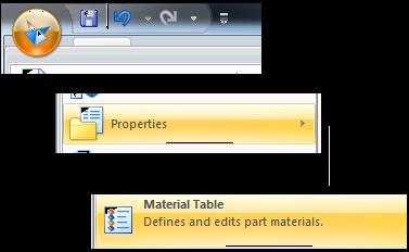

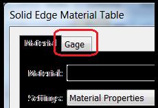
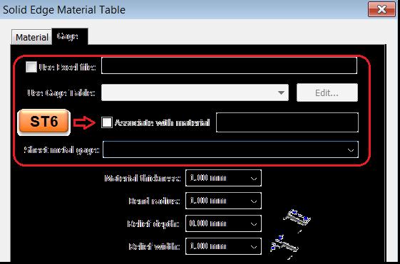
8 Defining Gage Material Application->Properties->Material Table->Material Tab Gage Application- >Properties->Material Table->Gage Tab Associate with Material moved from Material page drop down to Gage tab ST6 Page 8

9 Defining Bend Properties Bend Radius Application- >Properties->Material Table->Bend Radius Tools->Variables->BendRadius Bend Relief Application- >Properties->Material Table->Relief<Width/Depth> Tools->Variables-> Relief<Width/Depth> Page 9

10 Defining Neutral Factor Neutral Factor Application- >Properties->Material Table->Gage Tab Use Excel File Users can use Gagetable.xls to define their own materials, bend radii, bend reliefs and also neutral factors for various bend radii and bend angles. Bend Equation group Users can define their own neutral factor through a VB program Tools->Variables->Neutral Factor Neutral factor can also be defined for each individual bend in Sync or per feature in Ordered Page 10


11 Overriding Sheet Metal Properties In Ordered bend parameters (Radius, Bend relief & NF) can be overridden at the feature level Feature->Options In Sync bend parameters (Radius, Bend relief & NF) can be overridden by selecting the bend and using the bend handle Bend->Bend Handle->Options Page 11
12 Sheet Metal Parts Straight Brake & Rolled Sheet Metal parts can be created in multiple ways Start with the Sheet Metal template for a dedicated document Create a Sheet Metal part in a Part document Typical usage Change in design intent i.e., starts as regular part but it needs to be a Sheetmetal part now Translated parts Behaviour Document type is unchanged i.e., still a Part document Sheetmetal properties added to the Part document Sheetmetal environment activated Sheetmetal parts can be created and edited like in native Sheetmetal documents Remember SE can create rolled parts too Use contour flange as a starting point ST5 Page 12


13 ST6 Sheet Metal on Part Models ST6 offers capabilities to create SM features on thin portions of a regular part - only Ordered Think stamped parts Sheet Metal features supported Flanges, Contour Flanges Deform features on thin portions Page 13
14 ST6 Quick Enhancements Dimple and Drawn Cutout have been enhanced to support multiple profiles Already supported in Sync Only closed profiles Bead already supports multiple profiles Dynamic Preview during SM feature creation Most features now display a preview Add Flat_Pattern_Model_CutSize variables in templates Allows users to expose these through custom properties even if a flat patters does not exist Flatten Simplify b-splines option set to OFF Associate with Material moved from Material page drop down to Gage age Page 14


15 ST6 Flatten Enhancements Unbend, rebend and flat pattern have been enhanced to support features on cylindrical bends Flat features need to be created in ST6 Unbend, rebend & flat pattern Page 15
16 Transform to Sheet Metal Typical workflow Translated Parts Need to flatten or change thickness Change in requirements Starts as Part and needs to be Sheetmetal now Feature(s) Transform to Sync Sheetmetal (Ordered/Sync) Transform to Sheetmetal (Ordered) Automatically adds bends Option to rip the model Cut Users can custom rip the part ST5 Note Transform commands are enabled in Part documents from ST5 If in Part and want to work in Ordered, Transition to Ordered, Switch To Part and then run Transform to Sheetmetal command Page 16
17 Breaking into Sync Sheet Metal The When? Straight break bend parts Start with Tabs, Flanges and holes Graduate towards Contour Flanges, Patterns, Mirror Editing translated SM parts Thickness change, shape change, bend parameters etc Remember Integrated modelling The Why? Easy creation, easier edits Multiple flange creation Transforming translated SM parts to native SM parts Flange creation from Assembly Individual bend control Non-orthogonal plates/tabs And a lot more. Page 17
18 ST6 More.. The following ST6 enhancements will be covered in the Advanced Topic 503 tomorrow Emboss Flanges on linear edges Bends Contour Flanges Deform Features Contour flanges on contour flanges Features on Bends Dimples, beads, drawn cuts etc Flatten Enhancements Support deform features, part features and Emboss on bends When to use Sync/Ordered Integrated modelling Page 18

19 Questions? Ganapathy Kunda Page 19
 factor Page 20")
20 A primer on bending Bending, flat length computation and neutral (k) factor Page 20 #SEU13
21 Bending Bending causes the inside surface to be compressed and outside to be stretched. In practice what this means is that using the bend arc length on either layer face for determining the flat length will be incorrect. Or using the plate lengths including the bends will also result in incorrect flat length -Use outer layer lengths Use inner layer lengths Use just plate lengths up to bends Or what happens when you create a bend on a flat? Page 21
22 Flat lengths Computation of flat correct lengths involves accounting for the material transition during the bending process. The constants are the tab lengths either to the inside of the bend or to the outside of the bend Flat length = A + B Bend Deduction Flat length = C + D + Bend Allowance Bend allowance (BA) PI * (inside bend radius + neutral factor * material thickness) * bend angle/180 Bend deduction (BD) = 2 * outside set back Bend Allowance Page 22
23 What is Neutral Factor (K-Factor)? Between the inside and the outside surfaces, there is a layer which is neither compressed nor stretched. This is known as the neutral layer. Neutral factor helps determine the location of the neutral layer. Neutral factor depends on bend radius, bend angle, ambient temperature, direction of material grain, bending methods etc. Neutral layer helps determine the correct length of bend. References: Wiki Article, look at the references section in the article for more details Page 23
Using NX Sheet Metal for Design and Manufacture
 Using NX Sheet Metal for Design and Manufacture Dave Walker, NX Industry Product Manager Restricted Siemens AG 2017 Realize innovation. NX Sheet Metal Vision and Value Vision Design for fabrication, within
Sheet Metal Overview. Chapter. Chapter Objectives
 Chapter 1 Sheet Metal Overview This chapter describes the terminology, design methods, and fundamental tools used in the design of sheet metal parts. Building upon these foundational elements of design,
Wayne Mahan, GTAC. Converting a Solid Body to Sheet Metal
 Wayne Mahan, GTAC Converting a Solid Body to Sheet Metal Realize innovation. About Myself Page 2 Wayne Mahan Application Engineer, GTAC Solid Edge wayne.mahan@siemens.com I am a GTAC Application Engineer
WILDFIRE 4.0. Sheetmetal Assembly of a Bucket. Yves Gagnon, M.A.Sc. SDC
 INTRODUCTION TO PRO/SHEETMETAL WILDFIRE 4.0 Sheetmetal Assembly of a Bucket Yves Gagnon, M.A.Sc. SDC PUBLICATIONS Schroff Development Corporation www.schroff.com www.schroff-europe.com Estimated time:
WILDFIRE 3.0. Sheetmetal Assembly of a Bucket. Yves Gagnon, M.A.Sc. SDC
 INTRODUCTION TO PRO/SHEETMETAL WILDFIRE 3.0 Sheetmetal Assembly of a Bucket Yves Gagnon, M.A.Sc. SDC PUBLICATIONS Schroff Development Corporation www.schroff.com www.schroff-europe.com Estimated time:
Solid Edge ST3. for Engineers and Designers. CADCIM Technologies 525 St. Andrews Drive Schererville, IN 46375, USA (
 Solid Edge ST3 for Engineers and Designers CADCIM Technologies 525 St. Andrews Drive Schererville, IN 46375, USA (www.cadcim.com) Contributing Author Sham Tickoo Professor Department of Mechanical Engineering
Aerospace Sheet Metal Design
 CATIA V5 Training Foils Aerospace Sheet Metal Design Version 5 Release 19 January 2009 EDU_CAT_EN_ASL_FI_V5R19 1 About this course Objectives of the course Upon completion of this course you will be able
Aerospace Sheet Metal Design
 CATIA V5 Training Foils Aerospace Sheet Metal Design Version 5 Release 19 January 2009 EDU_CAT_EN_ASL_FF_V5R19 1 About this course Objectives of the course Upon completion of this course you will be able
SheetMetal Design Version 5 Release 13. SheetMetal Design
 SheetMetal Design Page 1 Overview Conventions What's New? Getting Started Entering the Workbench Defining the Parameters Creating the First Wall Creating the Side Walls Creating a Cutout Creating Automatic
Aerospace Sheetmetal Design
 Aerospace Sheetmetal Design Page 1 Overview Conventions What's New? Getting Started Entering the Aerospace SheetMetal Design Workbench Defining the Aerospace SheetMetal Parameters Creating a Web from a
401 - Getting the Most Out of Solid Edge Assembly Design
 4 th Generation VLC courtesy of Edison2 401 - Getting the Most Out of Solid Edge Assembly Design Art Patrick, Assembly Product Manager, #SEU13 About: Art Patrick Art Patrick Assembly Product Manager Art
414 - Creating 2D Layouts, Schematics and Other 2D Drawings
 4 th Generation VLC courtesy of Edison2 414 - Creating 2D Layouts, Schematics and Other 2D Drawings Ricky Black, Draft Product Manager, #SEU13 Agenda: 414 - Creating 2D Layouts, Schematics and Other 2D
Experience the power of over 25 years of continued development.
 Flattening Software Nesting Software For SOLIDWORKS For Progressive & Transfer Dies as well as for Multislide & Fourslide Tooling DIE Die Design DESIGN BLANK STRIP LAYOUT NESTING... I can design small
SOLIDWORKS - SYLLABUS
 SOLIDWORKS - SYLLABUS SolidWorks Syllabus 1 Introduction to CAD, CAE, PDM Features of SolidWorks, Total Duration : 90 Hour Various products available in SolidWorks for Product Design, Simulation, Communication
422 - Getting the Most out of Surfacing
 4 th Generation VLC courtesy of Edison2 422 - Getting the Most out of Surfacing Dan Vinson, Part Product Manager, 19930 #SEU13 Agenda: 422 - Getting the Most out of Surfacing Who am I? What you will learn
SOLID EDGE SOLID EDGE SOLID EDGE SOLID EDGE SOLID EDGE SOLID EDGE SOLID EDGE SOLID EDGE SOLID EDGE SOLID EDGE SOLID EDGE SOLID EDGE SOLID EDGE SOLID
 SOLID EDGE SHEET METAL Solutions for Sheet Metal The sheet metal mode is the best I have ever used. I would put it up against anything available today. Bob Martin, Computer-Aided Engineering Magazine review
Engineering Design with SolidWorks 2015 and Video Instruction
 Engineering Design with SolidWorks 2015 and Video Instruction A Step-by-Step Project Based Approach Utilizing 3D Solid Modeling NEW Contains a new chapter on additive manufacturing David C. Planchard,
TRAINING SESSION Q3 2016
 There are 6 main topics in this training session which is focusing on 3D Import and 2D Drawing Tips and Tricks in IRONCAD. Content 3D modeling kernels... 2 3D Import... 3 Direct Face Modeling... 5 Unfold
What s new in Solid Edge ST6?
 4th Generation VLC courtesy of Edison2 Siemens PLM Software What s new in Solid Edge ST6? Design better. Benefits Open up new market opportunities with more realistic product designs Lower part costs without
SIEMENS. Multi-body modeling. spse01537
 SIEMENS Multi-body modeling spse01537 Proprietary and restricted rights notice This software and related documentation are proprietary to Siemens Product Lifecycle Management Software Inc. 2015 Siemens
SolidWorks 2014 Part II - Advanced Techniques
 SolidWorks 2014 Part II - Advanced Techniques Parts, Surfaces, Sheet Metal, SimulationXpress, Top-Down Assemblies, Core and Cavity Molds Paul Tran CSWE, CSWI SDC PUBLICATIONS Better Textbooks. Lower Prices.
Engineering Design with SOLIDWORKS 2018
 Engineering Design with SOLIDWORKS 2018 and Video Instruction A Step-by-Step Project Based Approach Utilizing 3D Solid Modeling David C. Planchard, CSWP, SOLIDWORKS Accredited Educator SDC PUBLICATIONS
SolidWorks 2013 Part II - Advanced Techniques
 SolidWorks 2013 Part II - Advanced Techniques Parts, Surfaces, Sheet Metal, SimulationXpress, Top-Down Assemblies, Core and Cavity Molds Paul Tran CSWE, CSWI Supplemental Files SDC PUBLICATIONS Schroff
SOLIDWORKS 2019 Advanced Techniques
 SOLIDWORKS 2019 Advanced Techniques Mastering Parts, Surfaces, Sheet Metal, SimulationXpress, Top Down Assemblies, Core & Cavity Molds Paul Tran CSWE, CSWI SDC PUBLICATIONS Better Textbooks. Lower Prices.
128 - FEA Model Preparation using Solid Edge's Synchronous Technology
 4 th Generation VLC courtesy of Edison2 128 - FEA Model Preparation using Solid Edge's Synchronous Technology Kevin Baxter, Consultant Page 1 #SEU13 Agenda: 128 - FEA Model Preparation using Solid Edge's
SOLIDWORKS: Lesson III Patterns & Mirrors. UCF Engineering
 SOLIDWORKS: Lesson III Patterns & Mirrors UCF Engineering Solidworks Review Last lesson we discussed several more features that can be added to models in order to increase their complexity. We are now
This document summarizes some of what s new that have been deployed with Solid Edge Version ST3. For more information visit the website of Solid DNA
 What s new Solid Edge ST3 Introduction guide to what s new This document summarizes some of what s new that have been deployed with Solid Edge Version ST3. For more information visit the website of www.soliddna.com
What's New in NX 11 for Design Engineering
 What's New in NX 11 for Design Engineering NX 11 for Design Productivity Convergent Modeling Many industries use scanned 3D data as part of their design processes. If you have worked with this data in
Routing in Your Products: Frames, Wiring, and XpresRoute
 Ronnie Conerly, Product Manager, Routing in Your Products: Frames, Wiring, and XpresRoute Solid Edge University 2014 May 12-14, Atlanta, GA, USA SOLID EDGE UNIVERSITY 2014 Re-imagine What s Possible #SEU14
1 All rights reserved SpaceCAD Ltd
 . ( ).,.., : 1.,. 2.,. -.. 1.,, Family of Parts PathFinder. 2..,,.,.,,..,., Update,...,,,..,.,..,,.,.,. 1 ,,.,.,.,,. Solid Edge,.,., Home Tables Parts List., Auto-Balloon Parts List., Balloons., Parts
Plate 'n' Sheet Development Version 4 Professional Edition. Module 1
 Module 1 1. Introduction and Overview 2. Create a Shape 3. Develop a Pattern 4. Use the Viewing Controls 5. Getting Help Richard Stewart 2007 R & L CAD Services Pty Ltd Mackay QLD AUSTRALIA Page 1 Table
Mechanical Design CATIA - Structure Design 1 (SR1) CATIA V5R20
 CATIA V5R20") Mechanical Design CATIA - Structure Design 1 (SR1) CATIA V5R20 Mechanical Design CATIA - Structure Design Rapidly design structures using catalogues of standard or custom sections Product overview CATIA
Mechanical Design CATIA - Structure Design 1 (SR1) CATIA V5R20 Mechanical Design CATIA - Structure Design Rapidly design structures using catalogues of standard or custom sections Product overview CATIA
Ronnie Conerly, Product Manager, Siemens PLM Software. Advanced Piping & Tubing
 Ronnie Conerly, Product Manager, Advanced Piping & Tubing Agenda Who am I? What you will learn Solid Edge Capabilities Demonstrations Benefits of this topic How to Learn More Wednesday, 3:00-4:00 PM Page
SOLIDWORKS 2016: A Power Guide for Beginners and Intermediate Users
 SOLIDWORKS 2016: A Power Guide for Beginners and Intermediate Users The premium provider of learning products and solutions www.cadartifex.com Table of Contents Dedication... 3 Preface... 15 Part 1. Introducing
604 - Drafting in Solid Edge: A Hands-on Experience
 4 th Generation VLC courtesy of Edison2 604 - Drafting in Solid Edge: A Hands-on Experience Steve Webb, Solid Edge Field Support, #SEU13 Agenda: 604 - Drafting in Solid Edge: A Hands-on Experience Who
Creo 2.0. Curriculum Guide
 Creo 2.0 Curriculum Guide Live Classroom Curriculum Guide Update to Creo Parametric 2.0 from Creo Elements/Pro 5.0 Update to Creo Parametric 2.0 from Pro/ENGINEER Wildfire 4.0 Introduction to Creo Parametric
Glider. Wing. Top face click Sketch. on the Standard Views. (S) on the Sketch toolbar.
 on the Sketch toolbar.") Chapter 5 Glider Wing 4 Panel Tip A. Open and Save As "WING 4 PANEL". Step 1. Open your WING BLANK file. Step 2. Click File Menu > Save As. Step 3. Key-in WING 4 PANEL for the filename and press ENTER.
Chapter 5 Glider Wing 4 Panel Tip A. Open and Save As "WING 4 PANEL". Step 1. Open your WING BLANK file. Step 2. Click File Menu > Save As. Step 3. Key-in WING 4 PANEL for the filename and press ENTER.
Advanced CAD Modelling Course (SolidWorks 2009)
") Advanced CAD Modelling Course (SolidWorks 2009) Published by: The National Centre for Technology in Education And T4 Technology Subjects Support Service National Centre for Technology in Education Dublin
Advanced CAD Modelling Course (SolidWorks 2009) Published by: The National Centre for Technology in Education And T4 Technology Subjects Support Service National Centre for Technology in Education Dublin
Radan Release Notes Radan 2016
 Radan Release Notes Radan 2016 This information package contains an overview of changes introduced in the Radan 2016 issue of software. If you have any questions relating to the changes made, please contact
Module 5: Creating Sheet Metal Transition Piece Between a Square Tube and a Rectangular Tube with Triangulation
 1 Module 5: Creating Sheet Metal Transition Piece Between a Square Tube and a Rectangular Tube with Triangulation In Module 5, we will learn how to create a 3D folded model of a sheet metal transition
Module 1: Basics of Solids Modeling with SolidWorks
 Module 1: Basics of Solids Modeling with SolidWorks Introduction SolidWorks is the state of the art in computer-aided design (CAD). SolidWorks represents an object in a virtual environment just as it exists
The World s Leading Stamping Die Design Software for AutoCAD!
 DIE is a comprehensive suite of AutoCAD based software products designed to automate many facets of the stamping die design process. DIE software modules can operate independently to address specific design
Sheet Metal Design: Understanding Corner Relief Design Flexibility
 AUTODESK INVENTOR 2008 WHITE PAPER Sheet Metal Design: Understanding Corner Relief Design Flexibility The enhanced Flange and Contour Flange commands in Autodesk Inventor 2008 software now enable selection
Curriculum Guide. Creo 4.0
 Curriculum Guide Creo 4.0 Live Classroom Curriculum Guide Update to Creo Parametric 4.0 from Creo Parametric 3.0 Introduction to Creo Parametric 4.0 Advanced Modeling using Creo Parametric 4.0 Advanced
Autodesk Inventor : From Concept to Digital Prototype
 Autodesk Inventor : From Concept to Digital Prototype Bryan Fields Advanced Solutions, Inc. MA305-5 Using the tools available in Autodesk Inventor, this session will look at the progression from concept
Pro/ENGINEER Wildfire 3.0 Curriculum Guide
 Pro/ENGINEER Wildfire 3.0 Curriculum Guide NOTE: For a graphical depiction of the curriculum based on job role, please visit this page: http://www.ptc.com/services/edserv/learning/paths/ptc/proe_wf3.htm
105 - Synchronizing History
 4 th Generation VLC courtesy of Edison2 105 - Synchronizing History Matt Lombard, Solid Edge Employee #SEU13 Agenda: 105 - Synchronizing History Who is Matt Lombard? Why you should mix methods (Synchronous
LASER & PUNCH CAM SOFTWARE
 LASER & PUNCH CAM SOFTWARE www.metamation.com MetaCAM s easy to use and powerful drafting system helps you breeze through part creation. Each drawing icon is designed to morph into several operations using
Stamp a Part Perfectly on the Very First Hit.
 Stamp a Part Perfectly on the Very First Hit. Using the right software tool it is possible. DYNAFORM allows you to accurately simulate the stamping of parts to predict formability issues, validate die
SHEETMETAL CAD/CAM SOFTWARE
 SHEETMETAL CAD/CAM SOFTWARE 2D-CAD The MetaCAM CAD engine allows users to start designing a part from scratch or import a variety of CAD files for processing on various sheet metal machinery. With the
Publication Number spse01695
 XpresRoute (tubing) Publication Number spse01695 XpresRoute (tubing) Publication Number spse01695 Proprietary and restricted rights notice This software and related documentation are proprietary to Siemens
Feature-Based Modeling and Optional Advanced Modeling. ENGR 1182 SolidWorks 05
 Feature-Based Modeling and Optional Advanced Modeling ENGR 1182 SolidWorks 05 Today s Objectives Feature-Based Modeling (comprised of 2 sections as shown below) 1. Breaking it down into features Creating
Creo 3.0. Curriculum Guide
 Creo 3.0 Curriculum Guide Live Classroom Curriculum Guide Update to Creo Parametric 3.0 from Creo Parametric 2.0 Introduction to Creo Parametric 3.0 Advanced Modeling using Creo Parametric 3.0 Advanced
First Looks: Striker Systems' Die Professional Software for stamping dies by Pat Davis
 Page 1 of 5 First Looks: Striker Systems' Die Professional Software for stamping dies by Pat Davis Die Professional is a collection of six products from Striker Systems-SS-DESIGN, SS-UNFOLD, SS-STRIP,
Revised Sheet Metal Simulation, J.E. Akin, Rice University
 Revised Sheet Metal Simulation, J.E. Akin, Rice University A SolidWorks simulation tutorial is just intended to illustrate where to find various icons that you would need in a real engineering analysis.
Finite Differencing Using Excel Learning how to use Surface Charts T 1 T 4 T 2 T 3
 Finite Differencing Using Excel Learning how to use Surface Charts T 1 T 2 T 4 T 2 Assuming a flat plate of a uniform thickness has four constant temperatures applied to outer and inner edges, the temperature
Sheet-Metal Design Using SolidWorks
 Sheet-Metal Design Using SolidWorks By EGS India Sheet Metal Capability Sheet Metal Flexible Working Environment Blank Development Controlling Parameters Forming Tool Sheet Metal Design Tools Sheet Metal
Equipment Support Structures
 Equipment Support Structures Overview Conventions What's New? Getting Started Setting Up Your Session Creating a Simple Structural Frame Creating Non-uniform Columns Creating Plates with Openings Bracing
Parametric Modeling with SOLIDWORKS 2017
 Parametric Modeling with SOLIDWORKS 2017 NEW Contains a new chapter on 3D printing Covers material found on the CSWA exam Randy H. Shih Paul J. Schilling SDC PUBLICATIONS Better Textbooks. Lower Prices.
Update to Creo Parametric 4.0 from Creo Parametric 2.0
 Update to Creo from Creo Parametric 2.0 Overview Course Code Course Length TRN-5125-T 16 Hours In this course, you will learn how to utilize the variety of functionality enhancements in Creo. You will
Equipment Support Structures
 Page 1 Equipment Support Structures Preface Using This Guide Where to Find More Information Conventions What's New? Getting Started Setting Up Your Session Creating a Simple Structural Frame Creating Non-uniform
Pro/ENGINEER Wildfire 2.0 Curriculum
 Pro/ENGINEER Wildfire 2.0 Curriculum Live Classroom Virtual Class Web Based NOTE: For a graphical depiction of the curriculum based on job role, please visit this page: http://www.ptc.com/services/edserv/learning/paths/ptc/proe_wf2.htm
Leading the Industry with Innovative CAD/CAM Solutions
 Leading the Industry with Innovative CAD/CAM Solutions Metamation, Inc. 2D CAD Align:X CenterLine Intersection Align:Y Intersection Tangent MetaCAM s easy to use and powerful drafting system helps you
Chapter 11 Solar Car Drawing
 Chapter 11 Solar Car Drawing A. Insert Top and Side Views. Step 1. Click File Menu > New, click Drawing and OK. Step 2. Click Browse Step 3. Select your solar car assembly file and click Open. Step 4.
Simulation of Roller Hemming Process to Correlate the Design Parameters
 Simulation of Roller Hemming Process to Correlate the Design Parameters Madhavi B. Raskar Student of Mechanical Engineering Department Sinhgad Academy of Engineering, Pune. Prof. S. C. Shilwant HOD of
Inventor What s New
 Inventor 2009 - First and Last Name Presenter s Title 2008 Autodesk 1 Simulation Perform more advanced analysis with less setup time Parametric Gear Joints Reference Frames Spatial Joint 3D Contact Enhancement
Autodesk Fusion 360 Training: The Future of Making Things Attendee Guide
 Autodesk Fusion 360 Training: The Future of Making Things Attendee Guide Abstract After completing this workshop, you will have a basic understanding of editing 3D models using Autodesk Fusion 360 TM to
Parametric Piping Models. Naveed Anwar July 2003
 Parametric Piping Models Naveed Anwar July 2003 The Idea Basic idea is to assign parametric objects to basic line or area objects in the SAP2000 model and then generate detailed mesh for each object, on-demand
Live Classroom Curriculum Guide
 Curriculum Guide Live Classroom Curriculum Guide Creo Elements/Pro 5.0 (formerly Pro/ENGINEER Wildfire 5.0) Update from Pro/ENGINEER Wildfire 4.0 Creo Elements/Pro 5.0 (formerly Pro/ENGINEER Wildfire 5.0)
Input CAD Solid Model Assemblies - Split into separate Part Files. DXF, IGES WMF, EMF STL, VDA, Rhino Parasolid, ACIS
 General NC File Output List NC Code Post Processor Selection Printer/Plotter Output Insert Existing Drawing File Input NC Code as Geometry or Tool Paths Input Raster Image Files Report Creator and Designer
Autodesk Inventor 6 Essentials Instructor Guide Chapter Four: Creating Placed Features Chapter Outline This chapter provides instruction on the follow
 Chapter Four: Creating Placed Features Chapter Outline This chapter provides instruction on the following topics and provides exercises for students to practice their skills. Day Two Topic: How to create
3 AXIS STANDARD CAD. BobCAD-CAM Version 28 Training Workbook 3 Axis Standard CAD
 3 AXIS STANDARD CAD This tutorial explains how to create the CAD model for the Mill 3 Axis Standard demonstration file. The design process includes using the Shape Library and other wireframe functions
Module 4B: Creating Sheet Metal Parts Enclosing The 3D Space of Right and Oblique Pyramids With The Work Surface of Derived Parts
 Inventor (5) Module 4B: 4B- 1 Module 4B: Creating Sheet Metal Parts Enclosing The 3D Space of Right and Oblique Pyramids With The Work Surface of Derived Parts In Module 4B, we will learn how to create
Solid Modeling: Part 1
 Solid Modeling: Part 1 Basics of Revolving, Extruding, and Boolean Operations Revolving Exercise: Stepped Shaft Start AutoCAD and use the solid.dwt template file to create a new drawing. Create the top
Live Classroom Curriculum Guide
 Curriculum Guide Live Classroom Curriculum Guide Milling using Pro/ENGINEER Wildfire 4.0 Pro/ENGINEER Mechanica Simulation using Pro/ENGINEER Wildfire 4.0 Introduction to Pro/ENGINEER Wildfire 4.0 Pro/ENGINEER
429 - Solid Edge - Tips and Tricks
 4 th Generation VLC courtesy of Edison2 429 - Solid Edge - Tips and Tricks Craig Ruchti, Solid Edge Field Support, #SEU13 Agenda: 429 - Solid Edge - Tips and Tricks Who am I? What you will learn Solid
COPYRIGHT DASSAULT SYSTEMES Version 5 Release 19 January 2009 EDU-CAT-EN-ASL-FS-V5R19
 CATIA Training CATIA Aerospace Sheet Metal Design Detailed Steps COPYRIGHT DASSAULT SYSTEMES Version 5 Release 19 January 2009 EDU-CAT-EN-ASL-FS-V5R19 Table of Contents Additional Exercise: Aerostructure...3
SOLIDWORKS Parametric Modeling with SDC. Covers material found on the CSWA exam. Randy H. Shih Paul J. Schilling
 Parametric Modeling with SOLIDWORKS 2015 Covers material found on the CSWA exam Randy H. Shih Paul J. Schilling SDC PUBLICATIONS Better Textbooks. Lower Prices. www.sdcpublications.com Powered by TCPDF
GrafiCalc Examples. Here are nineteen (19) examples that illustrate proven applications of GrafiCalc technology.
 examples that illustrate proven applications of GrafiCalc technology.") GrafiCalc Examples Here are nineteen (19) examples that illustrate proven applications of GrafiCalc technology. The examples have been arranged to show the following capabilities. 1. Predictive engineering
GrafiCalc Examples Here are nineteen (19) examples that illustrate proven applications of GrafiCalc technology. The examples have been arranged to show the following capabilities. 1. Predictive engineering
to Market Faster Bringing Innovative Medical Products inspiration
 white paper Bringing Innovative Medical Products to Market Faster inspiration SUMMARY To succeed in today s medical device manufacturing industry, product designers must not only create innovative medical
Electrical Cableway Routing
 Electrical Cableway Routing Preface Using This Guide What's New? Getting Started Entering the Workbench Placing a Hanger Routing a Loft Through Hangers Placing a Conduit on a Run Saving Documents Updating
Autodesk Inventor 2018
 Parametric Modeling with Autodesk Inventor 2018 NEW Contains a new chapter on 3D printing Randy H. Shih SDC PUBLICATIONS Better Textbooks. Lower Prices. www.sdcpublications.com Powered by TCPDF (www.tcpdf.org)
PTC Technical Specialists E-Newsletter Date: December 1, 2006
 PTC Technical Specialists E-Newsletter Date: December 1, 2006 PTC Product Focus: A) What s New in Sheetmetal Design for Wildfire 3.0 B) Windchill 3 rd Party Workgroup Managers Tips of the Month: A) Creating
You will need the following items: scissors, plate, 5 different colored pencils, protractor, paper to answer questions
 Radian measure task You will need the following items: scissors, plate, 5 different colored pencils, protractor, paper to answer questions Instructions will follow on each slide. Feb 19 10:33 AM Step 1
Solid Edge. Key features 2D Drafting Design and drafting Foundation Classic Premium
 Solid Edge software is a complete hybrid 2D/3D CAD system that uses synchronous technology for accelerated design, faster revisions and better imported re-use to help companies design better. Solid Edge
Bottle Rocket. Drawing. on the Com- on the View Layout
 Chapter 6 Bottle Rocket Drawing A. Insert Views. Step 1. Click File Menu > New, click Drawing Metric and OK. on the Com- Step 2. Click View Layout mand Manager toolbar. Step 3. Click Model View toolbar.
ANSYS Workbench Guide
 ANSYS Workbench Guide Introduction This document serves as a step-by-step guide for conducting a Finite Element Analysis (FEA) using ANSYS Workbench. It will cover the use of the simulation package through
Start VTube-STEP, then follow these steps:
 This is a quick-start guide that shows how to perform a basic import of a simple STEP file (the demo 3 part) and then export the data to a bender using the Supravision Network Ethernet protocol. The steps
Create Complex Surfaces
 Create Complex Surfaces In this lesson, you will be introduced to the functionalities available in the Generative Surface Design workbench. Lesson content: Case Study: Surface Design Design Intent Stages
Parametric Modeling with SolidWorks
 Parametric Modeling with SolidWorks 2012 LEGO MINDSTORMS NXT Assembly Project Included Randy H. Shih Paul J. Schilling SDC PUBLICATIONS Schroff Development Corporation Better Textbooks. Lower Prices. www.sdcpublications.com
Publication Number spse01695
 XpresRoute (tubing) Publication Number spse01695 XpresRoute (tubing) Publication Number spse01695 Proprietary and restricted rights notice This software and related documentation are proprietary to Siemens
Improving Productivity with Parameters
 Improving Productivity with Parameters Michael Trull Rocky Brown Thursday, January 25, 2007 Improving Productivity with Parameters Part I The Fundamentals Parameters are variables which define the size
How to Design Custom Enclosures for Motherboard-Based Systems
 PROTOCASE TECHNICAL BULLETIN How to Design Custom Enclosures for Motherboard-Based Systems (covering ATX and Mini ITX form factors) Document Edition - 1 Last Updated: June 6 th,2011 Protocase, Inc. All
Constructing treatment features
 Constructing treatment features Publication Number spse01530 Constructing treatment features Publication Number spse01530 Proprietary and restricted rights notice This software and related documentation
Run Specifi by clicking on the icon on your Desktop.
 Run Specifi by clicking on the icon on your Desktop. Note: If you are using a demo version, once the program is loaded, a message will tell you the remaining days of the evaluation period. The main screen
WinAqua TUTORIAL WinAqua
 WinAqua TUTORIAL WinAqua WinAqua TUTORIAL Copyright SOFiSTiK AG, D-81514 Műnchen, 1990-2002 This documentation is protected by copyright. No part of it may be reproduced, translated or rewritten in any
PATHFINDER3D Help. Updated September 26, Page 1 of 40
 PATHFINDER3D Help Updated September 26, 2012 Page 1 of 40 Contents Introduction... 4 Product Description... 4 How to use this document... 4 Terms... 4 Procedures... 5 Installing... 5 Configuring... 6 Licensing...
Autodesk Inventor 2016 Learn by doing. Tutorial Books
 Autodesk Inventor 2016 Learn by doing Tutorial Books Copyright 2015 Kishore This book may not be duplicated in any way without the express written consent of the publisher, except in the form of brief
Solid Edge: Solutions for the top 10 engineering challenges. White Paper
 Solid Edge: Solutions for the top 10 engineering challenges White Paper With respect to 3D design, Solid Edge software is the best choice for accelerating design in the overall process of bringing products
THE BEST CHOICE FOR 3D CAD. ALIBRE DESIGN 7.0 USER GUIDE.
 ALIBRE DESIGN THE BEST CHOICE FOR 3D CAD. ALIBRE DESIGN 7.0 USER GUIDE www.alibre.com Alibre Design 7.0 User Guide Copyrights Information in this document is subject to change without notice. The software