Parametric Piping Models. Naveed Anwar July 2003
|
|
|
- Augusta Sims
- 6 years ago
- Views:
Transcription
1 Parametric Piping Models Naveed Anwar July 2003
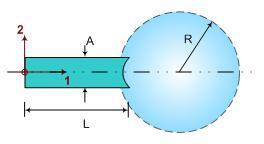
2 The Idea Basic idea is to assign parametric objects to basic line or area objects in the SAP2000 model and then generate detailed mesh for each object, on-demand using physical dimensions and parameters of the respective objects The object parameters as well as its location in overall model can be modified any time and mesh re-generated
3 The Process The User Draws simplified line model Assigns the piping objects to the line objects Set the properties of the piping objects The Program Generates a Detailed Line Model Generates a Detailed Shell Model Generates a Mixed Model
4 Basic Object Types Pipes and Tubes Vessels Bends Joints and Connections Transitions Caps and Covers Pedestals
5 The Basic Line Model The line object model created in SAP2000 Objects are assigned to various line objects Parameters for each object assigned in separate templates and forms

6 The Parametric Models 1. Pedestal 5 2. Cap 4 3. Pipe 6 4. Cap 5. Bends Transition 7. Pipe 8. S-Bend Pipe 10. Bend Pipe and Transition 1


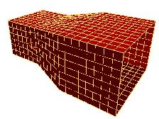
7 The Generated Model The Model The Mesh

8 Object Based Model The Line Model Meshed Model


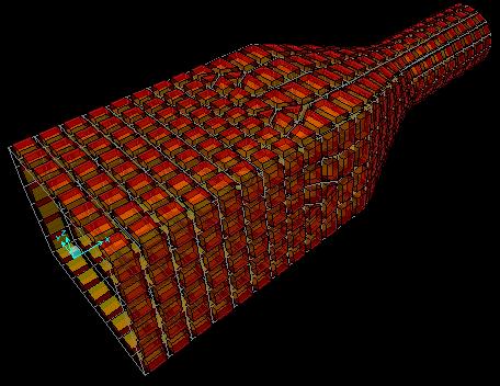
9 Generated Shell Model
10 The Detailed Line Model The User Line Model The Generated Line Model


11 Parametric Models 1. Pipe 2. Bend, Sharp 3. Pipe 4. Bend, Sharp 5. Pipe 6. Bend, Arc 7. Joint

12 Parametric Models 1. Pedestal 2. Joint 3. Bend, Arc 4. Pipe 5. Bend, Arc 6. Pipe 7. Tube 8. Pedestal

13 Parametric Models 1. Graded Tube 2. Transition 3. Pipe 4. Joint Pipe 6. Transition 7. Transition Pipe

14 Parametric Models 1. Tube Joint 2. Tube 3. Transition Pipe Pipe Joint
15 Mesh Clipping A tool for Meshing of Junction and Intersections

16 Mesh Clipping Mesh clipping is used as the basic tool to create mesh at object intersections Four 3D Mesh Clippings are used Mesh Clipped by Plane Mesh Clipped by Pipe Mesh Clipped by Tube Mesh Clipped by Sphere Direct Mesh Intersection is computed using Triangle-Triangle Intersection


17 Mesh Clipped by Plane Given Mesh is clipped at the intersection of a Plane Defined by 3-Points Mesh above and below the plane is returned


18 Mesh Clipped by Pipe Given Mesh is clipped at the intersection of a pipe defined by diameter and centerline Mesh inside and outside the pipe is returned


19 Mesh Clipped by Tube Given Mesh is clipped at the intersection of a rectangular tube defined by b x h and centerline Mesh inside and outside the tube is returned


20 Mesh Clipped by Sphere Given Mesh is clipped at the intersection of a sphere defined by diameter and center Mesh inside and outside the sphere is returned
21 Object Intersections


22 Pipe and Plate Intersection Pipe Cut By Two Planes


23 Pipes and Plates Intersection

24 General 3-Pipe Junction


25 General 3-Pipe Junction


26 General Multi-pipe Junction


27 Cut Pipes Before Weld Pipe 1 Pipe 2 Pipe 4 Pipe 3


28 Mesh Unwrapping Mesh Intersection Result Flat Sheet Equivalent For Cutting Etc.


29 Sheets Before Pipes Pipe2 Pipe3 Pipe4


30 Sphere and Pipe Junction Holes Cut by Pipes The Assembly The Subtracted Sphere
31 Basic Piping Objects


32 Nuclear Plant Piping U Expansion Double Offset Expansion Single Offset U Double Offset U


33 Nuclear Plant Piping


34 Pipe and Vessel Pedestals

35 PLATES


36 Parametric Model Parametric Model


37 Parametric Model Parametric Model


38 Parametric Model Parametric Model


39 Parametric Model Parametric Model


40 Parametric Model Parametric Model
41 PIPES AND TUBES


42 Parametric Model Parametric Model


43 Parametric Model Parametric Model


44 Parametric Model Parametric Model


45 Parametric Model Parametric Model


46 Parametric Model Parametric Model
47 CONNECTIONS


48 Parametric Model Parametric Model


49 Parametric Model Parametric Model


50 Parametric Model Parametric Model


51 Parametric Model Parametric Model


52 Parametric Model

53 Transitions


54 Parametric Model Parametric Model


55 Parametric Model
1 Classification of Shell Forms
 Proceedings of the 5 th International Conference on Computation of Shell and Spatial Structures June 1-4, 2005 Salzburg, Austria E. Ramm, W.A. Wall, K.-U. Bletzinger, M. Bischoff (eds.) www.iassiacm2005.de
Tutorial on Qualification of Nozzles attached to Spherical/Cylindrical Vessels using CAEPIPE
 Tutorial on Qualification of Nozzles attached to Spherical/Cylindrical Vessels using CAEPIPE The following are the steps for qualifying nozzles welded to Spherical/Cylindrical Vessels such as pressure
Solid Modeling: Part 1
 Solid Modeling: Part 1 Basics of Revolving, Extruding, and Boolean Operations Revolving Exercise: Stepped Shaft Start AutoCAD and use the solid.dwt template file to create a new drawing. Create the top
Technical Education Services
 Autodesk Fusion 360: Introduction to Parametric Modeling Course Length: 3 days Official Training Guide The Autodesk Fusion 360 Introduction to Parametric Modeling training course provides you with an understanding
Parametric Modeling with SOLIDWORKS 2017
 Parametric Modeling with SOLIDWORKS 2017 NEW Contains a new chapter on 3D printing Covers material found on the CSWA exam Randy H. Shih Paul J. Schilling SDC PUBLICATIONS Better Textbooks. Lower Prices.
Lesson 14 Blends. For Resources go to > click on the Creo Parametric 2.0 Book cover
 Lesson 14 Blends Figure 14.1 Cap OBJECTIVES Create a Parallel Blend feature Use the Shell Tool Create a Hole Pattern REFERENCES AND RESOURCES For Resources go to www.cad-resources.com > click on the Creo
Version 4.1 Demo. RecurDynTM 2002 RecurDyn User Conference
 Version 4.1 Demo RecurDynTM 2002 RecurDyn User Conference What s New? Using Parasolid Kernel Solid Modeler Other Program Interfaces New Data Structure New & Improved Features What s New? Using Parasolid
Autodesk Inventor 2019 and Engineering Graphics
 Autodesk Inventor 2019 and Engineering Graphics An Integrated Approach Randy H. Shih SDC PUBLICATIONS Better Textbooks. Lower Prices. www.sdcpublications.com Powered by TCPDF (www.tcpdf.org) Visit the
What's New in Autodesk Inventor 2020
 What's New in Autodesk Inventor 2020 This year we celebrate Inventor's 20-year anniversary with the release of Inventor 2020. This release delivers a host of enhancements to help you solve complex product
SOLIDWORKS 2016 and Engineering Graphics
 SOLIDWORKS 2016 and Engineering Graphics An Integrated Approach Randy H. Shih SDC PUBLICATIONS Better Textbooks. Lower Prices. www.sdcpublications.com Powered by TCPDF (www.tcpdf.org) Visit the following
EASTERN CANADA. NEW ENGLAND. QUEBEC
 Discover the UtilsXperts Phone: 1 877.876.5439 Fax: 1 877.876.5431 l info@solidxperts.com l www.solidxperts.com Page 1 Discover the UtilsXperts A series of utilities developed by SolidXperts and free for
SOLIDWORKS Parametric Modeling with SDC. Covers material found on the CSWA exam. Randy H. Shih Paul J. Schilling
 Parametric Modeling with SOLIDWORKS 2015 Covers material found on the CSWA exam Randy H. Shih Paul J. Schilling SDC PUBLICATIONS Better Textbooks. Lower Prices. www.sdcpublications.com Powered by TCPDF
CADMATIC is a registered trademark of CADMATIC Oy. All other trademarks are the property of their respective owners.
 Diagram Outfitting & Plant Design Hull Information Management: eshare, ebrowser, ego Release highlights 2018T2 Version 2018T2 includes many additions that increase the productivity of work in 3D and the
Extraction of Strut and Tie Model From 3D Solid Element Mesh Analysis
 International Conference on Sustainable Built Environment Extraction of Strut and Tie Model From 3D Solid Element Mesh Analysis Dammika Abeykoon, Naveed Anwar, Jason C. Rigon ICSBE 2010 12-14 December
ASME Verification and Validation Symposium May 13-15, 2015 Las Vegas, Nevada. Phillip E. Prueter, P.E.
 VVS2015-8015: Comparing Closed-Form Solutions to Computational Methods for Predicting and Validating Stresses at Nozzle-to-Shell Junctions on Pressure Vessels Subjected to Piping Loads ASME Verification
Geometric Modeling Topics
 Geometric Modeling Topics George Allen, george.allen@siemens.com Outline General background Convergent modeling Multi-material objects Giga-face lattices Page 2 Boundary Representation (b-rep) Topology
Learning. Modeling, Assembly and Analysis SOLIDWORKS Randy H. Shih SDC. Better Textbooks. Lower Prices.
 Learning SOLIDWORKS 2016 Modeling, Assembly and Analysis Randy H. Shih SDC PUBLICATIONS Better Textbooks. Lower Prices. www.sdcpublications.com Powered by TCPDF (www.tcpdf.org) Visit the following websites
Parametric Modeling with SolidWorks
 Parametric Modeling with SolidWorks 2012 LEGO MINDSTORMS NXT Assembly Project Included Randy H. Shih Paul J. Schilling SDC PUBLICATIONS Schroff Development Corporation Better Textbooks. Lower Prices. www.sdcpublications.com
Topology Optimization for Designers
 TM Topology Optimization for Designers Siemens AG 2016 Realize innovation. Topology Optimization for Designers Product Features Uses a different approach than traditional Topology Optimization solutions.
Freeform / Freeform PLUS
 Freeform / Freeform PLUS WORKING WITH FREEFORM Work from Coarse Clay to Fine When creating new models from scratch, it is best to first create a rough shape using a coarse clay setting such as Rough Shape
Autodesk Inventor 2018
 Parametric Modeling with Autodesk Inventor 2018 NEW Contains a new chapter on 3D printing Randy H. Shih SDC PUBLICATIONS Better Textbooks. Lower Prices. www.sdcpublications.com Powered by TCPDF (www.tcpdf.org)
Architectural Trim & Moldings
 Architectural Trim & Moldings Often, it s the subtle touches that make the biggest impact. With Stylmark s TrimMaker, you can easily add accent to walls, ceilings, soffits and columns, or provide a smooth
Engineering Drawing II
 Instructional Unit Basic Shading and Rendering -Basic Shading -Students will be able -Demonstrate the ability Class Discussions 3.1.12.B, -Basic Rendering to shade a 3D model to apply shading to a 3D 3.2.12.C,
Lesson 14 Blends. For Resources go to > click on the Creo Parametric Book cover
 Lesson 14 Blends Figure 14.1 Cap OBJECTIVES Create a Parallel Blend feature Use the Shell Tool Create a Swept Blend REFERENCES AND RESOURCES For Resources go to www.cad-resources.com > click on the Creo
SolidWorks 2013 and Engineering Graphics
 SolidWorks 2013 and Engineering Graphics An Integrated Approach Randy H. Shih SDC PUBLICATIONS Schroff Development Corporation Better Textbooks. Lower Prices. www.sdcpublications.com Visit the following
Ronnie Conerly, Product Manager, Siemens PLM Software. Advanced Piping & Tubing
 Ronnie Conerly, Product Manager, Advanced Piping & Tubing Agenda Who am I? What you will learn Solid Edge Capabilities Demonstrations Benefits of this topic How to Learn More Wednesday, 3:00-4:00 PM Page
Routing in Your Products: Frames, Wiring, and XpresRoute
 Ronnie Conerly, Product Manager, Routing in Your Products: Frames, Wiring, and XpresRoute Solid Edge University 2014 May 12-14, Atlanta, GA, USA SOLID EDGE UNIVERSITY 2014 Re-imagine What s Possible #SEU14
Spring 2011 Workshop ESSENTIALS OF 3D MODELING IN RHINOCEROS February 10 th 2011 S.R. Crown Hall Lower Core Computer Lab
 [1] Open Rhinoceros. PART 1 INTRODUCTION [4] Click and hold on the Boundary Lines in where they form a crossing and Drag from TOP RIGHT to BOTTOM LEFT to enable only the PERSPECTIVE VIEW. [2] When the
Autodesk AutoCAD In Mechanical Engineering Design Edward Locke
 Autodesk AutoCAD In Mechanical Engineering Design Edward Locke Engineering Department Santa Ana College Mechanical Engineering Drafting Essentials Working Drawings: Orthographic Projection Views (multi-view,
Mechanical Design CATIA - Structure Design 1 (SR1) CATIA V5R20
 CATIA V5R20") Mechanical Design CATIA - Structure Design 1 (SR1) CATIA V5R20 Mechanical Design CATIA - Structure Design Rapidly design structures using catalogues of standard or custom sections Product overview CATIA
Mechanical Design CATIA - Structure Design 1 (SR1) CATIA V5R20 Mechanical Design CATIA - Structure Design Rapidly design structures using catalogues of standard or custom sections Product overview CATIA
Module 4A: Creating the 3D Model of Right and Oblique Pyramids
 Inventor (5) Module 4A: 4A- 1 Module 4A: Creating the 3D Model of Right and Oblique Pyramids In Module 4A, we will learn how to create 3D solid models of right-axis and oblique-axis pyramid (regular or
2014 Geometry Summer Reading Assignment
 Name 2014 Geometry Summer Reading Assignment Date Prior to the first day of Geometry class, you must complete all questions contained in this packet. Geometry is a high school requirement and information
SolidWorks 2013 Part II - Advanced Techniques
 SolidWorks 2013 Part II - Advanced Techniques Parts, Surfaces, Sheet Metal, SimulationXpress, Top-Down Assemblies, Core and Cavity Molds Paul Tran CSWE, CSWI Supplemental Files SDC PUBLICATIONS Schroff
Introduction to ANSYS DesignModeler
 Lecture 5 Modeling 14. 5 Release Introduction to ANSYS DesignModeler 2012 ANSYS, Inc. November 20, 2012 1 Release 14.5 Preprocessing Workflow Geometry Creation OR Geometry Import Geometry Operations Meshing
ANSYS Element. elearning. Peter Barrett October CAE Associates Inc. and ANSYS Inc. All rights reserved.
 ANSYS Element Selection elearning Peter Barrett October 2012 2012 CAE Associates Inc. and ANSYS Inc. All rights reserved. ANSYS Element Selection What is the best element type(s) for my analysis? Best
Chapter 4 Feature Design Tree
 4-1 Chapter 4 Feature Design Tree Understand Feature Interactions Use the FeatureManager Design Tree Modify and Update Feature Dimensions Perform History-Based Part Modifications Change the Names of Created
Autodesk Inventor 6 Essentials Instructor Guide Chapter Four: Creating Placed Features Chapter Outline This chapter provides instruction on the follow
 Chapter Four: Creating Placed Features Chapter Outline This chapter provides instruction on the following topics and provides exercises for students to practice their skills. Day Two Topic: How to create
Ultima X5000 Round Duct Mount Kit User Instructions
 Ultima X5000 Round Duct Mount Kit User Instructions MSA Kit 10179124/10179321 - Ultima X5000 316 Stainless Steel Parts List / Instructions Round Duct Mount Gasket (1) Round Duct Mount Base Plate (1) Base
3D Modeling and Design Glossary - Beginner
 3D Modeling and Design Glossary - Beginner Align: to place or arrange (things) in a straight line. To use the Align tool, select at least two objects by Shift left-clicking on them or by dragging a box
Piping Design. Site Map Preface Getting Started Basic Tasks Advanced Tasks Customizing Workbench Description Index
 Piping Design Site Map Preface Getting Started Basic Tasks Advanced Tasks Customizing Workbench Description Index Dassault Systèmes 1994-2001. All rights reserved. Site Map Piping Design member member
Architectural Trim & Moldings
 Architectural Trim & Moldings Often, it s the subtle touches that make the biggest impact. With Stylmark s TrimMaker, you can easily add accent to walls, ceilings, soffits and columns to provide a smooth
LASER & PUNCH CAM SOFTWARE
 LASER & PUNCH CAM SOFTWARE www.metamation.com MetaCAM s easy to use and powerful drafting system helps you breeze through part creation. Each drawing icon is designed to morph into several operations using
Solid Bodies and Disjointed Bodies
 Solid Bodies and Disjointed Bodies Generally speaking when modelling in Solid Works each Part file will contain single solid object. As you are modelling, each feature is merged or joined to the previous
Armacell Training Course
 Registration form Course Syllabus - Bronze / Silver / Gold: Preferred course dates: Trainee: Name and Home Address Business Address Contact Telephone Number Employment Status: Self-Employed Direct / Contracted
Input CAD Solid Model Assemblies - Split into separate Part Files. DXF, IGES WMF, EMF STL, VDA, Rhino Parasolid, ACIS
 General NC File Output List NC Code Post Processor Selection Printer/Plotter Output Insert Existing Drawing File Input NC Code as Geometry or Tool Paths Input Raster Image Files Report Creator and Designer
CHANNEL BLOCK SOLID. Step 7. For the Placement Point, click the bottom left gray rectangle and click OK. to fit drawing on the screen.
 Chapter 9 CHANNEL BLOCK SOLID A. Create Rectangle. Step 1. Change to the Front View. Use green Front View or ALT-6 F. Hold down ALT and press 6. Key-in F. Step 3. Create. Step 4. Rectangle. Step 5. 1 Point.
Kully Reference Book
 Kully Reference Book Serving the Greater Mid-West since 1946 Angles Channels Beams Rounds Sheets Squares Flats Rebar Wire Mesh Black & Galvanized Pipe Anchor Bolts Plastic, Copper, Black, Galvanized Pipe
SOLIDWORKS Simulation
 SOLIDWORKS Simulation Length: 3 days Prerequisite: SOLIDWORKS Essentials Description: SOLIDWORKS Simulation is designed to make SOLIDWORKS users more productive with the SOLIDWORKS Simulation Bundle. This
Module 6B: Creating Poly-Conic Sheet Metal Pieces for a Spherical Space
 1 Module 6B: Creating Poly-Conic Sheet Metal Pieces for a Spherical Space In Module 6B, we will learn how to create a folded 3D model of an approximate 2D flat pattern for a 120-inch or 10-foot diameter
VTube-LASER Quick Start Guide for FARO QUANTUM from a Traditional Tube Print
 VTube-LASER Quick Start Guide for FARO QUANTUM from a Traditional Tube Print This guide shows how to setup VTube-LASER from a tube print and then measure and qualify demo tube 4 using a FARO ScanArm. A
Element Order: Element order refers to the interpolation of an element s nodal results to the interior of the element. This determines how results can
 TIPS www.ansys.belcan.com 鲁班人 (http://www.lubanren.com/weblog/) Picking an Element Type For Structural Analysis: by Paul Dufour Picking an element type from the large library of elements in ANSYS can be
2D CAD. Courseware Issued: DURATION: 64 hrs
 2D CAD Introduction File management Orthographic drawings View management Display management Layer management Selection methods Parametric drawings Symbol creation using block BOM / Joinery details creation
Materialise Magics 23. What s new
 Materialise Magics 23 What s new Index UX/UI Improvements View cube and general toolbar Settings Performance improvements Magics RP Fillet Cut or punch: lap joint cut Boolean Honeycomb structures Tools
Module 5: Creating Sheet Metal Transition Piece Between a Square Tube and a Rectangular Tube with Triangulation
 1 Module 5: Creating Sheet Metal Transition Piece Between a Square Tube and a Rectangular Tube with Triangulation In Module 5, we will learn how to create a 3D folded model of a sheet metal transition
Table of contents. What is new in Advance Steel 2014 WELCOME TO ADVANCE STEEL USER INTERFACE ENHANCEMENTS... 6 MODELING JOINTS...
 Table of contents WELCOME TO ADVANCE STEEL 2014... 5 USER INTERFACE ENHANCEMENTS... 6 User interface 1: Customizable tool palette... 6 User interface 2: Collision check results... 7 User interface 3: Steel
User Guide. for. JewelCAD Professional Version 2.0
 User Guide Page 1 of 121 User Guide for JewelCAD Professional Version 2.0-1 - User Guide Page 2 of 121 Table of Content 1. Introduction... 7 1.1. Purpose of this document... 7 2. Launch JewelCAD Professional
2017T3. Release highlights. Diagram Outfitting & Plant Design Hull Information Management: eshare, ebrowser, ego
 Diagram Outfitting & Plant Design Hull Information Management: eshare, ebrowser, ego Release highlights 2017T3 Drafting styles and more straightforward handling of labels in the Diagram New navigation
Vario XtraSafe. Installation Guide. Installation Guide
 Vario XtraSafe Installation Guide Installation Guide Step 1 Ensure the area to which Vario XtraFix Tape is to be applied is clean and free from dust. Step 2 Remove the backing and apply XtraFix Tape in
SOLIDWORKS - SYLLABUS
 SOLIDWORKS - SYLLABUS SolidWorks Syllabus 1 Introduction to CAD, CAE, PDM Features of SolidWorks, Total Duration : 90 Hour Various products available in SolidWorks for Product Design, Simulation, Communication
Curriculum Guide. Creo 4.0
 Curriculum Guide Creo 4.0 Live Classroom Curriculum Guide Update to Creo Parametric 4.0 from Creo Parametric 3.0 Introduction to Creo Parametric 4.0 Advanced Modeling using Creo Parametric 4.0 Advanced
SOLIDWORKS 2019 Advanced Techniques
 SOLIDWORKS 2019 Advanced Techniques Mastering Parts, Surfaces, Sheet Metal, SimulationXpress, Top Down Assemblies, Core & Cavity Molds Paul Tran CSWE, CSWI SDC PUBLICATIONS Better Textbooks. Lower Prices.
Geometry Vocabulary. acute angle-an angle measuring less than 90 degrees
 Geometry Vocabulary acute angle-an angle measuring less than 90 degrees angle-the turn or bend between two intersecting lines, line segments, rays, or planes angle bisector-an angle bisector is a ray that
Engineering Design with SolidWorks 2015 and Video Instruction
 Engineering Design with SolidWorks 2015 and Video Instruction A Step-by-Step Project Based Approach Utilizing 3D Solid Modeling NEW Contains a new chapter on additive manufacturing David C. Planchard,
Publication Number spse01695
 XpresRoute (tubing) Publication Number spse01695 XpresRoute (tubing) Publication Number spse01695 Proprietary and restricted rights notice This software and related documentation are proprietary to Siemens
PP-R & PVC-U Products Catalogue
 PP-R & PVC-U Products Catalogue INDEX PP-R Products Page 3 PVC-U Products Page 7 Points To Pay Attention When Installing Ppr Pipes And Fittings Due to their brittle characteristic and behavior below 0
Skills Practice Skills Practice for Lesson 2.1
 Skills Practice Skills Practice for Lesson.1 Name Date Backyard Barbecue Introduction to Volume and Surface Area Vocabulary Write the term from the box that best completes each statement. surface area
Images from 3D Creative Magazine. 3D Modelling Systems
 Images from 3D Creative Magazine 3D Modelling Systems Contents Reference & Accuracy 3D Primitives Transforms Move (Translate) Rotate Scale Mirror Align 3D Booleans Deforms Bend Taper Skew Twist Squash
Hardware & Accessories
 Hardware & Accessories Assure that your installations and designs are completed in professional fashion by utilizing Stylmark s Hardware and Accessories. This catalog represents a collection of these items,
y = 4x + 2, 0 x 1 Name: Class: Date: 1 Find the area of the region that lies under the given curve:
 Name: Class: Date: 1 Find the area of the region that lies under the given curve: y = 4x + 2, 0 x 1 Select the correct answer. The choices are rounded to the nearest thousandth. 8 Find the volume of the
Mechanical Design V5R19 Update
 CATIA V5 Training Foils Mechanical Design V5R19 Update Version 5 Release 19 August 2008 EDU_CAT_EN_MD2_UF_V5R19 1 About this course Objectives of the course Upon completion of this course you will be able
Autodesk Inventor 2016
 Parametric Modeling with Autodesk Inventor 2016 Randy H. Shih SDC PUBLICATIONS Better Textbooks. Lower Prices. www.sdcpublications.com Powered by TCPDF (www.tcpdf.org) Visit the following websites to learn
TILBURY STEEL SERVICE CENTRE
 TILBURY STEEL SERVICE CENTRE 159 Queen Street North Tilbury, ON, N0P 2L0 Voice: 519-682-0000 Toll-Free: 1-800-565-1077 Fax: 519-682-0004 Email: tsales@tilburysteel.com STOCK BOOK & REFERENCE GUIDE Tilbury
Lesson 13 Patterns and Weldments
 Lesson 13 Patterns and Weldments Figure 13.1 Mounting System Weldment OBJECTIVES Create directional patterns and dimensional patterns Pattern components on an assembly Insert multiple standard parts using
Toolbar Quick Reference
 Toolbar Quick Reference This document lists the commands in the Panel bars and Toolbars throughout Autodesk Inventor 2011 when using the Classic UI Layout application option. Refer to this document to
SolidWorks 2014 Part II - Advanced Techniques
 SolidWorks 2014 Part II - Advanced Techniques Parts, Surfaces, Sheet Metal, SimulationXpress, Top-Down Assemblies, Core and Cavity Molds Paul Tran CSWE, CSWI SDC PUBLICATIONS Better Textbooks. Lower Prices.
North US 290 US 183. MLK Blvd. FM 969. ASERO Steel Sales. Ben White TX 71 IH-35 US 183
 North US 290 US 8 MLK Blvd. FM 969 ASERO Steel Sales Ben White TX IH- US 8 Hot Rolled Strip Commercial Quality A - 0 Size in Per 20 Ft. /8 x /2.2 4.26 /4.9 6.8.42 8.0 /4. 0.62 /2.68 2.6 2.80.00 2 /2.06
Common grade: ASTM A36..min. 36,000 yield / min. 58,000 tensile. Size Weight (lbs.) Weight (lbs.)
 Weight (lbs.)") Bar Size Angle Common grade: ASTM A36..min. 36,000 yield / min. 58,000 tensile Size Weight (lbs.) Weight (lbs.) A B C per Foot per 20' 1/2 x 1/2 x 1/8 0.38 7.6 5/8 x 5/8 x 1/8 0.48 9.6 3/4 x 3/4 x 1/8
Bar Size Angle Common grade: ASTM A36..min. 36,000 yield / min. 58,000 tensile Size Weight (lbs.) Weight (lbs.) A B C per Foot per 20' 1/2 x 1/2 x 1/8 0.38 7.6 5/8 x 5/8 x 1/8 0.48 9.6 3/4 x 3/4 x 1/8
CHAPTER 6: APPLICATIONS OF INTEGRALS
 (Exercises for Section 6.1: Area) E.6.1 CHAPTER 6: APPLICATIONS OF INTEGRALS SECTION 6.1: AREA 1) For parts a) and b) below, in the usual xy-plane i) Sketch the region R bounded by the graphs of the given
Publication Number spse01695
 XpresRoute (tubing) Publication Number spse01695 XpresRoute (tubing) Publication Number spse01695 Proprietary and restricted rights notice This software and related documentation are proprietary to Siemens
1 All rights reserved SpaceCAD Ltd
 . ( ).,.., : 1.,. 2.,. -.. 1.,, Family of Parts PathFinder. 2..,,.,.,,..,., Update,...,,,..,.,..,,.,.,. 1 ,,.,.,.,,. Solid Edge,.,., Home Tables Parts List., Auto-Balloon Parts List., Balloons., Parts
SOLIDWORKS Costing is available in SOLIDWORKS Professional and SOLIDWORKS Premium.
 The SOLIDWORKS Costing tool helps you calculate how much it costs to manufacture sheet metal, machined, and multibody parts, as well as plastic molded, cast, 3D printed parts, and multibody weldments by
Cloth Simulation on the GPU. Cyril Zeller NVIDIA Corporation
 Cloth Simulation on the GPU Cyril Zeller NVIDIA Corporation Overview A method to simulate cloth on any GPU supporting Shader Model 3 (Quadro FX 4500, 4400, 3400, 1400, 540, GeForce 6 and above) Takes advantage
NX electrical and mechanical routing Accelerating design of mechanical and electrical routed systems in complex assemblies
 electrical and mechanical routing Accelerating design of mechanical and electrical routed systems in complex assemblies fact sheet www.ugs.com Summary software digital product development solutions include
Lesson 13 Patterns and Weldments
 Lesson 13 Patterns and Weldments Figure 13.1 Mounting System Weldment OBJECTIVES Create directional patterns Create dimensional patterns Pattern components on an assembly Insert multiple standard parts
The Rectangular Problem
 C h a p t e r 2 The Rectangular Problem In this chapter, you will cover the following to World Class standards: The tools for simple 2D Computer Aided Drafting (CAD) The Command Line and the Tray The Line
Step Shaft Design Analysis
 Step Shaft Design Analysis Shigley Problem 18-20 1. Obtain step shaft assembly from the shared drive, this assembly should include the step shaft and two bearing supports with constraints already provided.
Airetool Condenser Expanders Selection Guide G-900 Series Heat Exchanger and Condenser Tube Expanders. Airetool Heat Exchanger Condenser Expanders
 Airetool Heat Exchanger Condenser Expanders Step Rolling Step rolling is required when expanding tubes in thick tube sheets. Typically the first expansion is made at the innermost location, away from the
Spare part catalogue GB 03/2007. Wall-hung boilers ecotec exclusive 832, 838 VUW 326/4-7 VUW 386/4-7
 Spare part catalogue 0020037555.03 GB 03/2007 Wall-hung boilers ecotec exclusive 832, 838 VUW 326/4-7 VUW 386/4-7 Content General view of sheet Page 3 04 Burner Page 4 06 Heat exchanger Page 6 07 Casing
A Comprehensive Introduction to SolidWorks 2011
 A Comprehensive Introduction to SolidWorks 2011 Godfrey Onwubolu, Ph.D. SDC PUBLICATIONS www.sdcpublications.com Schroff Development Corporation Chapter 2 Geometric Construction Tools Objectives: When
Inventor 201. Work Planes, Features & Constraints: Advanced part features and constraints
 Work Planes, Features & Constraints: 1. Select the Work Plane feature tool, move the cursor to the rim of the base so that inside and outside edges are highlighted and click once on the bottom rim of the
Leading the Industry with Innovative CAD/CAM Solutions
 Leading the Industry with Innovative CAD/CAM Solutions Metamation, Inc. 2D CAD Align:X CenterLine Intersection Align:Y Intersection Tangent MetaCAM s easy to use and powerful drafting system helps you
SOLIDWORKS Flow Simulation 2015
 An Introduction to SOLIDWORKS Flow Simulation 2015 John E. Matsson, Ph.D. SDC PUBLICATIONS Better Textbooks. Lower Prices. www.sdcpublications.com Powered by TCPDF (www.tcpdf.org) Visit the following websites
Autodesk Inventor 2016 Learn by doing. Tutorial Books
 Autodesk Inventor 2016 Learn by doing Tutorial Books Copyright 2015 Kishore This book may not be duplicated in any way without the express written consent of the publisher, except in the form of brief
Release Notes. EC CAD - Fabrication for AutoCAD MEP. EC PartManager. EC DuctMaker
 Release Notes EC CAD - Fabrication for AutoCAD MEP EC PartManager EC DuctMaker Version 8.0 for Autodesk 2018 Copyright 2005-2017 EastCoast CAD/CAM. All rights reserved. This document and the information
Fits 1 3/4" Resilient Rings. Part # Shaft Height A" 92-A /4" 4.4" 92-A /4" 4.6" Fits 2 1/2" Resilient Rings. Part # Shaft Height A"
 Bases 48 Frame Resilient Mount Kit 92-A240 9" Blowers( 2 1/2" Rings) 92-A241 12" Blowers ( 2 1/2" Rings) 92-A242 10" Blowers (2 1/2" Rings) Accessories Base Mounting Adapter Kit For 5 1/2" with flat end
6. CAD SOFTWARE. CAD is a really useful tool for every engineer, and especially for all the designers.
 6. CAD SOFTWARE CAD is a really useful tool for every engineer, and especially for all the designers. Not only because it makes drawing easier, but because it presents the advantage that if any detail
Chapter 6. Concept Modeling. ANSYS, Inc. Proprietary Inventory # May 11, ANSYS, Inc. All rights reserved.
 Chapter 6 Concept Modeling 6-1 Contents Concept Modeling Creating Line Bodies Modifying i Line Bodies Cross Sections Cross Section Alignment Cross Section Offset Surfaces From Lines Surfaces From Sketches
403 - Getting the Most Out of Sheet Metal Modeling
 4 th Generation VLC courtesy of Edison2 403 - Getting the Most Out of Sheet Metal Modeling Jeff Walker, Product Planning Manager, #SEU13 Agenda: 403 - Getting the Most Out of Sheet Metal Modeling Who am
Sheet Metal Overview. Chapter. Chapter Objectives
 Chapter 1 Sheet Metal Overview This chapter describes the terminology, design methods, and fundamental tools used in the design of sheet metal parts. Building upon these foundational elements of design,
Start VTube-STEP, then follow these steps:
 This is a quick-start guide that shows how to perform a basic import of a simple STEP file (the demo 3 part) and then export the data to a bender using the Supravision Network Ethernet protocol. The steps