DA-CAD User Manual Dürkopp Adler AG
|
|
|
- Gertrude Hensley
- 5 years ago
- Views:
Transcription


1 DA-CAD 5000 User Manual
2 DA-CAD 5000 All rights reserved No parts of this work may be reproduced in any form or by any means - graphic, electronic, or mechanical, including photocopying, recording, taping, or information storage and retrieval systems - without the written permission of the publisher Products that are referred to in this document may be either trademarks and/or registered trademarks of the respective owners The publisher and the author make no claim to these trademarks While every precaution has been taken in the preparation of this document, the publisher and the author assume no responsibility for errors or omissions, or for damages resulting from the use of information contained in this document or from the use of programs and source code that may accompany it In no event shall the publisher and the author be liable for any loss of profit or any other commercial damage caused or alleged to have been caused directly or indirectly by this document Printed: Juni 2011 in Bielefeld, Germany Doc Version: 11 SW- Version: 20
3 Contents 3 Contents Part I Welcome 1-3 Part II 1 Steps 2-3 Part III The user interface Menu bar 3-4 File 3-4 Edit 3-10 Data transfer 3-10 Settings 3-11 Window 3-11 Help The Icon Menu Bar Function and information bar Tools menu bar Drawing box Table Status line 3-21 Part IV The drawing of seam programs Drawing a line Drawing a circular arc Drawing a spline curve Positioning a single stitch Defining a non-sewing movement 4-8 Part V Editing seam programs Editing a seam section 5-4 Selecting seam sections 5-5 Change configuration of seam section 5-6 Rotate the seam section 5-8 Mirroring a seam section 5-11 Mirror and copy 5-12 Move a seam section 5-13 Scale a seam section 5-15 Positioning a seam section 5-17 Duplicate a seam section 5-18 Generate an equidistant counterpart 5-20 Reverse seam direction 5-22 Delete all technology points 5-24 Deleting a seam section 5-24 Change to non-sew ing section 5-25 Interpolation 5-26 Sequence w indow Edit a support point 5-32
4 4 DA-CAD 5000 Selection of support points Moving a support point Delete a support point Insert Connect Move & Connect Divide seam sections Configuration of individual sections Edit stitch or stitches 5-49 Selection of stitches Move stitch Delete stitch Insert stitch Edit action point Part VI Data transfer to the machine 1 Dongle 6-3 Form at 6-4 Read contents 6-5 Saving to a dongle 6-7 Load 6-11 Delete USB memorystick (flash drive) 6-14 Saving to a USB "stick" flash drive 6-14 Load from a USB flash drive Part VII Input windows 1 Settings 7-3 Default param eters w indow 7-4 Configuration w indow for current seam section 7-8 Machine class 7-12 Language 7-12 Serial interface 7-13 Grid lines 7-13 Background im age Edit 7-15 Rotate Scale Move Generate an equidistant counterpart Positioning Duplicate Edit technology points Part VIII Context-sensitive menu Editing a seam section Editing a support point Editing stitches 8-5 Part IX Glossary and Refernce "What is a?" Reference 9-5
5 Contents Index 5
6
7 Part Welcome I
8

9 Welcome Welcome DA-CAD 5000 Dürkopp Adler welcomes you to the "DA-CAD 5000" software application for creating seam programs This software will enable you to develop seam programs on the PC for the Dürkopp Adler sewing machines and sewing units The application includes utilities which allow you to draw seam sections simply and intuitively After you draw the seam sections you can also edit the resulting stitches Operations such as scaling, moving and copying are possible The seam program which you create can then be transferred to the desired machine class using a data storage device (such as a USB stick/flash drive) The introductory chapter First Steps you to get to know this software 2-3 will present a summary of important issues in order to help The subsequent chapters present a detailed description of the user interface 3-3, the drawing process 4-3 and the editing 5-3 of seam programs including the data transfer to the machine 6-3
10
11 Part 1 Steps II
12
13 1 Steps Steps This section should help you to become more quickly familiar with the "DA-CAD 5000" software A general explanation or process summary of the individual subjects can be found here More detailed information is contained in the following chapters The structure of a seam program A seam program is made of individual seam sections These seam sections are described using support points including start and end points, as well as certain shapes (such as circular segments or spline curves) and additional mid-support points Each seam section is divided into stitches The processing views in the program are based on and correspond to these seam sections The program's processing views There are three different views when working with the program: Seam sections Drawing and editing seam sections Support points Editing support points Stitches Editing stitches Drawing of seam sections A variety of seam section shapes are available for drawing They can be activated in the "Drawing" toolbox: Line(s) Circular arc defined by three points Spline curve Rectangle Single stitch Non-sewn stitch The mouse can be used to draw directly in the drawing box Mouse actions Drawing action Establishing the coordinates for a seam section Mouse action Left mouse button End the drawing of seam sections with any number Right mouse button of support points (spline curves, lines) End the drawing of seam sections with a fixed number of support points (circular arcs) None (ends automatically after establishing the last support point) Cancel the drawing of seam sections with a fixed number of support points (circular arcs) Right mouse button
14 2-4 DA-CAD 5000 Edit Mouse action Select a seam section, support point or stitch Place the cursor on the seam section, support point or stitch Then click the left mouse button Use the left mouse button to pull out a border around the seam section Select multiple seam sections Position the cursor over the seam section; Press the CTRL key and the left mouse button Select multiple stitches Use the left mouse button to pull out a border around stitches Seam section All seam sections can be processed individually or in any combination The more important processing methods are: Scaling: using the menu or border + mouse Moving: using the menu or border + mouse Configuring: using the menu (stitch length, zigzag, etc) Mirroring (reflection) rotating via mouse in drawing box Support points Support points offer the following possibilities: They can be moved with the mouse Their coordinate values in the table can be changed They can be deleted A support point can also be added Stitches Stitches can be processed individually or selected in groups: Moving: move with the mouse or by the coordinate values in the table Deleting by in the table or in the drawing box To insert a stitch in the table:
15 1 Steps 2-5 Configuring the seam program Default values : valid for each new seam section, such as rotational speed, stitch length, with/without zigzag Seam section : each seam section can have its own configuration values Machine classes The drawing of a seam program is totally independent of the particular, selected machine class In the Icon menu bar, you can select a machine class and an appropriate sewing field with the icon Machine Class This allows parameters to be defined which are dependent on the machine type, such as rotational speed, maximum stitch length, or the maximum number of action points In addition, the format and type of data transmission is then determined (for example, dongle or USB)
16
17 Part The user interface III
18

19 The user interface The user interface The user interface consists of seven main fields: 1 The main menu bar 2 The Icon menu bar : a standard pull-down menu as found in standard Windows - applications : a standard icon menu, as found in standard Windows - applications 3 Function and information bar 3-15 : for selection of the view and special functions Drawing information is also displayed here (coordinates, class category, etc) 4 Tools menu bar 5 Drawing box 6 Table points Status bar etc : for selection of tools to draw and edit seam programs : box for drawing and editing seam programs : shows the X and Y coordinates for seam sections, support points, stitches and action 3-21 : displays context-sensitive help information, the COM interface which has been set,
20 DA-CAD 5000 Menu bar The main menu bar consists of: File 3-4 : functions for file handling, such as opening and saving Edit 3-10 : standard functions such as copying and pasting Data transfer 3-10 : creating, saving and importing files for transmitting to the machine via the data storage medium 311 Settings 3-11 : basic settings, such as for language and default parameters Window 3-11 : alignment and selection for opened windows Help : help file and information about the program 3-12 File Icon Name New Description Opens a new window The new window is opened with the same settings as the start-up setting for the program (machine class, sewing field, grid lines) Opens a saved seam program The file extension for seam programs is *fda Open Note: Files from "DAProgrammers" with the file extension *fkn can also be loaded This format does not include all information so the majority of the seam programs can only be accessed as individual stitches! Close Closes the current window This function is not available if only one window is closed If changes are made in a window, then you will be first asked to save your changes Save Saves the seam program in the current window using the current file name If no file name has been given since the file's creation, then the Save Menu is opened and you can specify a file name there The file extension for seam programs is *fda Save as Save as allows you to specify a file name to use for saving the seam program in the current window The file extension for seam programs is *fda Import Invoke the sub-menu for Importing other formats End This is used to exit the "DA-CAD 5000" software If changes are made in a window, then you will be first asked to save your changes before exiting 3-5
 AutoCAD DXF (*dxf) 31111 DST Work flow: steps for importing Tajima Files 1 Select the type and extension of the format from the menu File >")
21 The user interface Import This option allows you to import other, third-party formatted files These files can then be pasted into the current window The following formats can currently be imported: Type Extension Embroidery format Tajima (*dst) AutoCAD DXF (*dxf) DST Work flow: steps for importing Tajima Files 1 Select the type and extension of the format from the menu File > Import 2 The Import window opens automatically 3 After selecting the desired file, a preview of it is shown 4 Click on the Insert button in order to convert the file and paste it into the current window as a seam section 5 You can click on the Cancel button to leave the menu without making any changes
22 3-6 DA-CAD 5000

23 The user interface DXF Work flow: steps for importing DXF Files 1 Select the type and extension of the format from the menu File > Import 2 The Import window opens automatically 3 After selecting the desired file, a preview of it is shown 4 Kind of Auto sequence: off: All element are represented in order of the occurrence in the DXF file per Layer: Per Layer the contained elements are sorted in such a way that the elements are connected with the shortest distance over all Layer: Over all Layer the contained elements are sorted in such a way that the elements are connected with the shortest distance 5 With BLOCKS you can chose if the section BLOCKS should be included 6 With Scale you can change the dimensions of the imported data 7 Click on the Insert button in order to convert the file and paste it into the current window as a seam section 8 You can click on the Cancel button to leave the menu without making any changes

24 DA-CAD 5000 Exportieren This option allows you to export other, third-party formatted files The following formats can currently be imported: Art AutoCAD Typ DXF (*dxf) 3-7 Work flow: Export third-party formatted files 1 Select the type and extension of the format from the menu File > Import 2 The Import window opens automatically 3 Two possibilities exist of specifying which program is to be saved: a Current Program: The seam program on the current drawing board is stored b File select: Click on Browse to open the standard Windows file selection window Select the desired seam program and close the window
25 The user interface 4 The 3-9 icon is activated after a file is selected 5 Click on Icon to convert and save the selected seam program This window is automatically closed after the save operation is successfully completed 6 You can click on the Cancel button to leave the window without saving
26 DA-CAD 5000 Edit Icon 313 Name Description Undo The last action is undone (reversed) Up to 30 sequential actions can be undone Restore Once an action is undone, this command causes it to be recreated Copy Copy selected seam sections Insert Paste seam sections from the clipboard Cut Cut out the selected seam sections Delete Delete the selected seam sections 5-5 to the clipboard Data transfer Currently there are two different data transfer media which can be used for transfer to the machine: Dongle 3-10 : a DA memory stick for transfer connecting with DAC 3/4 controllers USB memory stick 3-11 : a standard USB flash drive The type used depends on the machine class Note: With both the dongle and the USB stick, class-specific data formats are used for saving to the storage medium These class-specific formats must be re-converted to a generic format when loading from the data storage medium Depending on the machine class, this reconversion process can result in loss of information Sub-menu: Dongle Icon Name Description Contents Load (dongle Save (PC The content of the dongle is displayed PC) dongle) The seam program is read from the dongle, converted to the PC format, and saved The seam program is converted to the class-specific dongle format and saved The dongle must be formatted Delete Seam programs on the dongle can be deleted Format This is used to create a machine-class-dependent dongle
27 The user interface 3-11 Sub-menu: USB memory stick Icon Name Load (USB Save (PC Description PC) USB) The seam program is read from the USB stick, converted to the PC format, and saved The seam program is converted to the class-specific USB format and saved For a detailed description of the data transfer process, please refer to the "Data transfer to the Machine" 6-3 chapter 314 Settings Icon Name Description Default parameters Opens up the input window for the class-specific default parameters 7-4 for the current window Machine class Opens the selection window for the machine class sewing field for the current window Interface Opens the settings window for the serial interface Language Opens the selection menu for the language Grid lines Opens the settings window for configuring the grid lines current window Background image Opens the selection window for configuring the background image 7-14 for the current window and the 7-13 in the Detailed information about the individual windows and menus can be found in the "Input Windows" chapter Window Icon Name Description Overlapping All opened windows are displayed with overlap Align horizontally All opened windows are aligned horizontally Align vertically All opened windows are aligned vertically In addition, all opened windows are listed You can select a window from this list to make it the current window
28 DA-CAD 5000 Help Icon Name Description Info Opens an information window showing the version number Help Opens the help file
29 The user interface The Icon Menu Bar Icon Name New Description Opens a new window The new window is opened with the same settings as the start-up setting for the program (machine class, sewing field, grid lines) Opens a saved seam program The file extension for seam programs is *fda Open Note: Files from the older "DAProgrammer" with the file extension *fkn can also be loaded This format does not include all information so the majority of the seam programs can only be accessed as individual stitches! Save Saves the seam program in the current window using the current file name If no file name has been given since the file's creation, then the Save Menu is opened and you can specify a file name there The file extension for seam programs is *fda Cut Cut out the selected seam sections Copy Copy selected seam sections to the clipboard Insert Paste seam sections from the clipboard Delete Delete the selected seam sections Undo The last action is undone (reversed) Up to 30 sequential actions can be undone Restore Once an action is undone, this command causes it to be recreated Zoom in Magnify the drawing box The zoom factor is increased by 10% Maximum zoom factor: 900 % Zoom out Zoom out of the drawing box The zoom factor is decreased by 10% Minimum zoom factor: 40 % Zoom 1:1 The zoom factor is set at 100% Background image You can activate or deactivate the background image for the current window This function is available when a background image has been selected in the menu Settings > Background image Drawing color A drawing color can be chosen for the current window Machine class Opens the selection window for the machine class sewing field for the current window Config seam section Opens the window for the Configuration sections Default parameters Open up the input window for the class-specific default parameters 7-4 for the current window Sequence window Opens the window to change the sequence and the of the selected seam 5-26 of seam sections
30 3-14 DA-CAD 5000 Icon Name Description Display table Display of the table of values the current window Enlarge table The presentation of the table can be enlarged if not all columns are visible Insert before A column is created before the active column and assigned a value ( insert support point 5-38 or insert stitch 5-55 ) Insert after A column is created after the active column and assigned a value ( insert support point 5-38 or insert stitch 5-55 ) Delete column The selected column is deleted 3-20 can be activated and deactivated for
31 The user interface Function and information bar 1 Icon group: Views There are three different views when working with the program: Seam sections Drawing and editing seam sections Support points Editing support points Stitches Editing stitches 2 Icon group: Continue and capture Continue The new seam section automatically begins with the end point of the last previously drawn seam section Thus the start point of the new seam section does not need to be set If the shared coordinates are somehow altered (for example, with a move), then this alteration influences both seam sections Capture When drawing support points, the point located closest to the intersecting grid lines is automatically selected as the coordinate value Grid lines can be changed in a configuration window Info group 31 Absolute: The actual, real coordinate position of the cursor in the drawing box 32 Relative: The position of the cursor relative to the last set support point is shown here 33 Length: The length from the last support point to the current cursor position is shown here 34 Zoom: The current zoom factor is shown here 35 Class: The selected class is shown here
32 DA-CAD 5000 Tools menu bar The tools menu bar consists of three tool boxes: Draw 3-16 : Tools for drawing seam sections Rotate & mirror Scale & move Interpolation : Tools for rotating and mirroring : Tools for scaling, moving, etc : Interpolate transition of sewing sections Divide & Connect 3-17 : Tool to divide connected seam sections Drawing tool box Icon Name Active Tool Line(s) Description Drawing tool remains active Drawing lines 4-4 Spline curve Drawing a spline curve with any number of points Circular segment Drawing a circular segment Single stitch Drawing a single stitch length! Non-sewn Drawing non-sewn points (three points on the segment) Be sure to observe the maximum stitch Rotate & mirror tool box Icon Name Description Rotate Rotate Rotate via menu Rotate the selected sewing section using the rotate window Horiz mirror Mirror horizontally Vert mirror Mirror vertically Horz mirror & copy Mirror horizontally and copy Vert mirror & copy Mirror vertically and copy 5-8 the selected sewing section at its center point the selected support point the selected support point the selected support point the selected support point
33 The user interface 3-17 Scale & move tool box Icon Name Description Scale Scale the selected support point using the scale window Equidistant Generate an equidistant sections Move Move Positioning To position Duplicate Duplicate Reverse seam direction Reverse 5-20 counterpart for the selected seam the selected seam sections using the move window the selected sections using the positioning window the selected seam sections the seam direction of the selected seam sections Delete action points Delete all action points Non-sewing Change to a non-sewing for the selected seam sections seam section Interpolation tool box Icon Name Description Start interpolation Interpolate Cancel interpolation Cancel the interpolation of the transitions 5-26 transition of sewing sections Divide & Connect tool box Icon Name Description Connect Connect Move & Connect Move and connect Divide Connected seam sections can be divided 5-40 two seam sections 5-43 two seam sections 5-46

34 DA-CAD 5000 Drawing box The drawing box is a canvas area which is used for drawing and editing seam sections, support points and stitches It consists of the following: Rulers 3-18 : horizontal and vertical The canvas or drawing area 3-19 Rulers: The unit of ruler measurement is the millimetre The rulers are subdivided by dashes The interval between the dashes in dependent on the current zoom factor: Distance between two interval dashes Zoom factor range 5 mm 40-50% 2 mm % 1 mm % 05 mm %
35 The user interface 3-19 When the cursor is located in the drawing box, its position is shown by a blue triangle on the rulers Drawing area The drawing area (canvas) is shown in two colours: white indicates the selected sewing field for the selected machine class If no machine class has been selected, the entire drawing area is white grey The areas shown in grey lie outside of the selected sewing field Drawing is allowed anywhere in the box, regardless of the colour of the drawing area If the seam program lies outside of the sewing field, this is first detected when the seam program is written to the class-specific data storage medium The drawing area can be subdivided using grid lines configuration window 7-13 These are configured 7-13 using a separate A background image can be depicted on the drawing area This can be set up in the menu Settings > Background image 3-11 Background images can be moved and scaled in the drawing area (with a process similar to seam sections 5-5 ) In order to fade in or fade out on the background image, use the icon in the Icon menu bar The Cartesian coordinates system is used at all times This can not be changed
36 DA-CAD 5000 Table The table is used both for showing the coordinate values of support points and stitches, as well as for changing these coordinate values There are two views available: Support points Stitches : with the seam section view : with the stitches view and support point 3-13 Support points view This view shows the absolute X and Y coordinate values of the support points based on the zero point of the coordinate system They can be changed here In addition, the seam section type is shown: Line(s) Circular arc Spline curve Single stitch Non-sewn stitch If two seam sections are connected to each other, the cells which show their coordinates are connected and shown in red[1] Stitches view You can select whether the coordinate values should be shown absolutely or relative to each other:

37 The user interface 3-21 Absolutely: All stitches are represented in X and Y values based absolutely on the zero point of the coordinate system Absolute coordinates are shown in black Relatively: All stitches within a seam section are shown relative to one other as X and Y values The first coordinate of a seam section is indicated absolutely Relative coordinates are shown in blue Both absolute and relative coordinates can be changed directly in the table Note: Remember that if a change is made to the relative coordinates in the table, this leads to a change in the absolute coordinates of the subsequent stitches in this seam section Action points: after the X/Y coordinates, there are columns for action points The number of action point columns depends on the class In order to edit action points, you should activate the appropriate cell in the table by double clicking An input window for editing technology points 5-56 then opens up 37 Status line In addition to the copyright notice, the important details are: [1]: A field used for showing context-sensitive help If an object (such as an icon) is covered by the cursor, after a short time a relevant help text appears here [2]: The number of configured serial interfaces is shown here This is set with the menu Settings > Interface 3-11
38
39 Part The drawing of seam programs IV
40
41 The drawing of seam programs The drawing of seam programs Note: You can only draw while in the "Seam sections" 3-13 view You will be automatically switched to the "Seam sections" view when you activate any of the drawing tools from the "Drawing" tools menu bar 3-16 A seam program consists of multiple seam sections which can be individually drawn and edited There are two methods for drawing seam sections: 1 A new, independent seam section can be created 2 The new seam sections continues from the previous seam section The end position of the previous seam section is automatically selected as the new start position of the new seam section and is not marked Several different contour types are available: Line 4-4 Circular arc Spline Single stitch 4-7 In addition, a non-sewing movement 4-8 can be defined
42 DA-CAD 5000 Drawing a line The section describes the following: How a new line 4-4 is drawn How a previous seam section is continued with a line 4-4 Note: The set default values 7-4 (seam length, rotational speed, etc) are valid for the new seam section Work flow: Drawing a line 1 Click on the Line icon found in the "Drawing" tools menu bar Position the mouse in the drawing box so that the cursor is over the desired starting coordinates Then confirm with the left mouse button 3 Position the mouse cursor over the line's end point and confirm selection with the left mouse button 4 If you want to continue this seam section with an additional line, go back and repeat step 3 5 If you are done and need no additional lines, click on the right mouse button Work flow: Resuming (continuing) a seam section with a line 1 Click on the Continue icon found in the Function bar 2 In the "Drawing" tools menu bar, 3-16 click on the Line icon The start position of the new line is the same as the end point of the previous seam section Thus it does not need to be set 3 Position the mouse cursor over the line's end point and confirm selection with the left mouse button 4 If you want to continue this seam section with an additional line, go back and repeat step 3 5 If you are done and require no additional lines, click on the right mouse button Note: With the pushed down icon Active Tool the drawing tool is still activated
43 The drawing of seam programs Drawing a circular arc The section describes the following: How a new circular arc 4-5 is drawn How a previous seam section is continued with a circular arc 4-5 Note: The set default values 7-4 (seam length, rotational speed, etc) are valid for the new seam section Work flow: Drawing a circular arc 1 In the "Drawing" tools menu bar, 3-16 click on the Circular arc icon 2 Position the mouse in the drawing box so that the cursor is over the desired starting coordinates Then confirm with the left mouse button 3 Position the mouse cursor over the circular arc's end point and confirm selection with the left mouse button 4 You can now extend the circular arc by moving the mouse Once the desired size has been reached, click on the left mouse button to confirm and end the operation 5 You can use the right mouse button to cancel the drawing before you have set the third point Work flow: Resuming (continuing) a seam section with a circular arc 1 Click on the Continue icon found in the Function bar 2 In the "Drawing" tools menu bar, 3-16 click on the Circular arc icon The start position of the arc is the same as the end point of the previous seam section Thus it does not need to be set 3 Position the mouse cursor over the circular arc's end point and confirm selection with the left mouse button 4 You can now extend the circular arc by moving the mouse Once the desired size has been reached, click on the left mouse button to confirm and end the operation 5 You can use the right mouse button to cancel the drawing before you have set the third point Note: With the pushed down icon Active Tool the drawing tool is still activated
44 DA-CAD 5000 Drawing a spline curve The section describes the following: How a new spline curve 4-6 is drawn How a previous seam section is continued with a spline curve 4-6 Note: The set default values 7-4 (seam length, rotational speed, etc) are valid for the new seam section A spline curve consists of at least three points (including the start and end points) The seam section is automatically discarded if the drawing ends after only two points Work flow: Drawing a spline curve 1 In the"drawing" tools menu bar, 3-16 click on the Spline curve icon 2 Position the mouse in the drawing box so that the cursor is over the desired starting coordinates Then confirm with the left mouse button 3 Position the mouse cursor over the next point on the spline curve and confirm selection with the left mouse button 4 Repeat step 3 to define additional spline points 5 End the drawing action by clicking on the right mouse button Work flow: Resuming (continuing) a seam section with a spline curve 1 Click on the Continue icon found in the Function bar 2 In the "Drawing" tools menu bar, 3-16 click on the Spline curve icon The start position of the arc is the same as the end point of the previous seam section Thus it does not need to be set 3 Position the mouse cursor over the next point on the spline curve and confirm selection with the left mouse button 4 Repeat step 3 to define additional spline points 5 End the drawing action by clicking on the right mouse button Note: With the pushed down icon Active Tool the drawing tool is still activated
45 The drawing of seam programs Positioning a single stitch Note: Single stitches are always sewn stitches If non-sewn positions need to be drawn, then you should program a non-sewing movement 4-8 for this purpose Work flow: Drawing a single stitch 1 In the "Drawing" tools menu bar, 3-16 click on the Single stitch icon 2 Position the mouse in the drawing box so that the cursor is over the desired coordinates Then confirm with the left mouse button 3 If additional single stitches are needed, go back to step 2 and repeat 4 After the point has been defined, the action is completed and no further action is required Note: An action point can be assigned to a single stitch using the "Reworking seam programs function 5-3 "
46 DA-CAD 5000 Defining a non-sewing movement A non-sewing movement is used to define a movement that is made outside of the sewing process This can be used, for example, to move around obstacles Work flow: Drawing a non-sewing movement 1 In the "Drawing" tools menu bar, 3-16 click on the Non-sewing icon 2 Position the mouse in the drawing box so that the cursor is over the desired coordinates Then confirm with the left mouse button 3 If an additional point is needed for a non-sewing movement, go back to step 2 and repeat 4 After the point has been defined, the action is completed and no further action is required Note: An action point can be assigned to a non-sewn coordinate using the "Reworking seam programs function 5-3 "
47 Part Editing seam programs V
48
49 Editing seam programs Editing seam programs A seam program consists of individual seam sections joined together These seam sections are described using support points including start and end points, as well as certain shapes (such as circular segments or spline curves) and additional mid-support points Each seam section is divided into stitches In order to edit a seam program, you must determine what will be edited: Seam sections 5-4 : the entire seam section can be edited, for example, by moving, scaling, or assigning a new stitch length Support point deleting it 5-32 : a support point in a seam section can be edited, for example, by moving or Stitch or stitches 5-49 : one or more stitches can be edited, for example, by assigning an action point, by moving, or deleting
50 DA-CAD 5000 Editing a seam section Note: Seam sections can be edited in the "Seam sections" 3-13 view Seam sections must first be selected or activated in the drawing box 5-5 before they can be edited The following types of seam sections are available: Line(s) Circular arc Spline curve Rectangle Single stitch Non-sewing stitch A variety of functions are available for editing the selected seam sections: Change configuration define a zigzag seam Rotate Mirror : the seam section can be mirrored either along the horizontal or vertical axis Mirror & copy Move 5-13 Scaling : here you can, for example, change the stitch length of the seam section or : the selected seam sections can be rotated to any angle around their mid-point : a copy can be inserted that is either a horizontal or vertical mirror (reflection) : the selected seam sections can be moved in any direction 5-15 : the selected seam sections can be scaled to the desired size Generate an equidistant counterpart seam sections 5-20 : an equidistant counterpart can be inserted for the selected Note: Dividing 5-46 sewing sections is made by editing support points
51 Editing seam programs Selecting seam sections Note: Seam selections can only be selected in the Seam section 3-13 view There are two ways to activate seam sections: click directly on the desired seam section pull out a border , around the desired seam section(s) Work flow: selecting seam sections directly 1 Position the mouse cursor over any point on the seam section 2 Select the seam section with the left mouse button 3 A border appears around the seam section 4 If you need to activate another seam section, position the mouse cursor over any point on the new seam section 5 Use the CTRL + left mouse button combination to select the seam section 6 The border will now enclose all of the activated seam sections 7 If you need to select another seam section, go to step 4 and repeat Work flow: Selecting seam sections by pulling out a border Note: The selected seam sections must be completely enclosed by the extended border 1 Position the mouse cursor over any point outside of the seam section that you wish to activate 2 Press and hold the left mouse button 3 A border will be extended when you press the left mouse button 4 The left mouse button can be released when the border encloses all of the desired seam section(s) 5 All of the seam sections are activated when they are completely enclosed by the border The border will now enclose all of the activated seam sections
52 DA-CAD 5000 Change configuration of seam section The following can be configured: Stitch length (or alternatively, the stitch count) ( new calculation for the support point), Whether or not the seam section have a zigzag shape ( Zigzag parameters ( new calculation for the support point), new calculation for the support point), technology points that need to be completed before the first stitch Note: All stitch-related technology points will be lost if a new calculation for the seam section is required Exception: technology points that are located on a start or end point of the newly configured seam section Work flow: Configuring seam sections 1 You must first select the seam sections that you want to configure in the drawing box 2 In the Icon menu bar, 3-13 click on the Seam section configuration 3 The configuration window for seam sections icon is then opened: 4 Make the changes in this window ( Config window description 7-8 ) and exit the menu by clicking
53 Editing seam programs 5-7 on OK If a new calculation is required, it will be automatically carried out 5 It is possible to cancel at any time 6 Undo resets all values back to what they were before the window was opened 7 By clicking on Default, all parameters are reset to the values of the default parameters 7-4 Note: If you are dealing with lines in the seam section, then the individual sections can be separately configured 5-46 by using their support points
54 DA-CAD 5000 Rotate the seam section There are two ways to rotate the seam sections: Rotate the selected seam sections in the drawing box 5-8 Rotate the selected seam sections in the rotate window 5-10 Work flow: Rotating seam sections 1 You must first select the seam sections that you want to rotate in the drawing box In the "Rotate, mirror & copy" tools menu bar, 3-16 click on the Rotate icon A rotation circle [1], a mid-point [2], and a rotational axis [3] are then visible around the seam section 3 Using the mouse, move the cursor over the intersection of the rotational axis and rotation circle When this point is located, the cursor changes its appearance: 4 In order to rotate the seam section, click on the left mouse button and hold down while moving the cursor in the desired direction (dragging) During this motion, the position of the axis and the current rotational angle are shown 5 When you release the left mouse button, the rotated position of the seam section is also shown in dashes
55 Editing seam programs If you wish to change this angle, go back to step 3 and the following steps 7 If the desired position has been reached, confirm with the right mouse button The new position will then be adopted 8 Cancel: You can cancel the rotate process at any time by clicking on the left mouse button outside of the rotational area
56 5-10 DA-CAD 5000 Work flow: Rotating seam sections using the rotate window 1 You must first select the seam sections that you want to rotate in the drawing box 2 In the "Rotate, mirror & copy" tools menu bar, 3 This opens up the Rotate click on the Rotate window 5-5 icon input window: 4 Enter the desired direction, angle and position of the centre ( Description of Rotate window close by clicking on Apply The move operation is then automatically carried out 7-15 ) and 5 You can cancel this window without any changes to the seam section by clicking on Cancel
57 Editing seam programs 514 Mirroring a seam section There are two methods for mirroring the selected seam sections: Mirroring along the horizontal middle axis of the seam sections 5-11 Mirroring along the vertical mid-perpendicular bisector of the seam sections 5-11 Work flow: Mirroring along the horizontal middle axis (= vertical mirroring) 1 You must first select the seam sections that you want to mirror in the drawing box 2 In the "Rotate, mirror & copy" tools menu bar, click on the Mirror vertically icon 3 The mirrored position is automatically implemented Work flow: Mirroring along the vertical mid-perpendicular bisector (= horizontal mirroring) 1 You must first select the seam sections that you want to mirror in the drawing box 2 In the "Rotate, mirror & copy" tools menu bar, The mirrored position is automatically implemented 5-5 click on the Mirror horizontally icon 5-11
58 DA-CAD 5000 Mirror and copy With the function "mirror and copy", a mirrored copy of the selected seam section is inserted There are two possibilities here: Mirroring and copy along the horizontal middle axis of the seam sections 5-12 Mirror and copy along the vertical mid-perpendicular bisector of the seam sections 5-12 Work flow: Mirror and copy along the horizontal middle axis (= vertical mirroring) Note: When performing a vertical mirror and copy, the lower border line of the seam section is always the mirroring axis The copied seam section is attached to the seam program! 1 You must first select the seam sections that you want to mirror in the drawing box 2 In the "Rotate, mirror & copy" tools menu bar, click on the Mirror and copy vertically icon 3 The seam section is then automatically copied in Work flow: Mirror and copy along the vertical mid-perpendicular bisector (= horizontal mirroring) Note: When performing a horizontal mirror and copy, the right vertical border line of the seam section is always the mirroring axis The copied seam section is attached to the seam program! 1 You must first select the seam sections that you want to mirror in the drawing box 2 In the "Rotate, mirror & copy" tools menu bar, icon click on the Mirror and copy horizontally 3 The seam section is then automatically copied in
59 Editing seam programs Move a seam section There are two methods available for moving the selected seam sections: Move in the drawing box by using the mouse 5-13 Move by changing parameters in the Move input window 7-19 Work flow: Move within the drawing box 1 You must first select the seam sections that you want to scale in the drawing box If you move the mouse cursor within the marking frame, the cursor takes the shape of the move symbol: 3 Hold down and press the left mouse button 4 Press down on the left mouse button and move the mouse in order to move the selected seam section 5 Release the mouse button when the desired position has been reached 6 The seam section is then automatically moved Work flow: Move using the input window 1 You must first select the seam sections that you want to scale in the drawing box 2 Click on the Move 3 This opens up the Move icon in the "Scaling and Moving" tool box 7-19 input window:
60 5-14 DA-CAD Enter the desired movement distance as absolute or relative values( Description of Move window 7-19 ) and close by clicking on OK The move operation is then automatically carried out 5 You can cancel this window without any changes to the seam section by clicking on Cancel
 the selected seam")
61 Editing seam programs Scale a seam section Note: A new calculation for the seam section is required with a scaling operation This causes all stitch-related action points and all stitch reworking operations to be lost Exception: Action points that are located on a start or end point of the scaled seam section There are two methods available for scaling (resizing) the selected seam sections: Scale in the drawing box by using the mouse 5-15 Scale by changing parameters in the Scale input window 7-17 Work flow: Scale within the drawing box 1 You must first select the seam sections that you want to scale in the drawing box In order to scale with the mouse, the cursor must be positioned over one of the eight scaling fields surrounding the marking frame When the cursor is over one of the scaling fields around the marking frame, it then changes to the scaling symbol shape The cursor symbol indicates which direction will be used for the scaling operation 3 Hold down and press the left mouse button 4 With the left mouse button pressed down, you can change the selected seam sections by moving the mouse

62 5-16 DA-CAD Release the left mouse button when the desired size is reached The newly scaled size will then be automatically adopted Work flow: Scale using the input window 1 You must first select the seam sections that you want to scale in the drawing box 2 Click on the Scale 3 This opens up the Scale icon in the "Scaling and Moving" tool box input window: 4 Enter the desired scale change as absolute or relative values ( Description of Scale window and close by clicking on OK The scale operation is then automatically carried out 7-17 ) 5 You can cancel this window without any changes to the seam section by clicking on Cancel
63 Editing seam programs Positioning a seam section With the function "Positioning a seam section" you can set the position of a margin point: Wotk flow : Positioning a seam section 1 You must first select the seam sections that you want to scale in the drawing box 2 Click on the Positioning of a seam section 5-5 icon in the "Scaling and Moving" tool box Mith the mouse choose one of the margin points or the center If you hit one of this points the cursor change his appearance: 3 Click left mouse button This opens the Set position input window: 4 Set position for the chosen point in the input window ( Positioning input window clicking on OK The move operation is then automatically carried out: 7-21 ) and close by
64 5-18 DA-CAD You can cancel this window without any changes to the seam section by clicking on Cancel 519 Duplicate a seam section Note: When duplicate a seam section the technology points of the original are also on the dupes Work flow: Duplicate as seam section 1 You must first select the seam sections that you want to duplicate in the drawing box 2 Click on the Duplicate 3 This opens up the Duplicate icon in the "Scaling and Moving" tool box input window: 4 Select number of dupes and the distance between two dupes and close by clicking on Apply The duplicate operation is then automatically carried out
65 Editing seam programs 5 You can cancel this window without any changes to the seam section by clicking on Cancel 6 You can reverse the seam direction of individual dupes ( Reverse seam direction 5-22 ) 5-19
66 5-20 DA-CAD Generate an equidistant counterpart Note: The action points of the original are not transferred when generating a new equidistant counterpart Work flow: Creating an equidistant counterpart 1 The seam section for which you want to form an equidistant counterpart should first be selected in the drawing box Click on the Equidistant 3 This opens up the Equidistant icon in the "Scaling and Moving" tool box input window: 4 Enter the desired number of equidistant counterparts and the gap between them ( Description of Equidistant window 7-20 ) and close by clicking on OK The desired equidistant counterparts are then created automatically
67 Editing seam programs You can cancel this window without any changes to the seam section by clicking on Cancel 6 It is possible to reverse the seam direction for individual equidistant counterparts ( Reverse seam direction 5-22 )

68 5-22 DA-CAD Reverse seam direction With this function you can reverse the seam direction for seam sections: Work flow: Reverse seam direction 1 The seam sections must first be selected in the drawing box 2 Click on the Reverse seam direction 5-5 icon in the "Scaling and Moving" tool box The reversal for the seam sections is then carried out automatically If multiple sequential seam sections are selected, then both the seam direction and the order of the seam sections are automatically reversed:
69 Editing seam programs 5-23 Note: After a reversal of seam direction, all action points are maintained at their original places Be sure to check if the action points are still intended at these positions (for example, when using a "cut" action point, or a rotational speed reduction) It is possible to delete all of the action points 5-24 in a single seam section
70 5-24 DA-CAD Delete all technology points This function allows you to delete all technology points for the selected seam sections To change or delete individual technology points, use the stitch editing 5-56 function Work flow: Delete technology points from a seam section 1 The seam sections must first be selected in the drawing box 2 Click on the Delete technology point icon 5-5 in the "Scaling and Moving" tool box All technology points from the selected seam section are then deleted 5113 Deleting a seam section Work flow: Deleting a seam section 1 You must first select the seam sections that you want to delete in the drawing box 2 Click on the Delete 5-5 icon to delete the selected seam sections 3 Alternatively, the selected seam sections can be deleted by using the Del key 4 The change is then automatically carried out in the seam program
71 Editing seam programs 5114 Change to non-sewing section With this function you can change sewing seam sections to non-sewing sections Hinweis: You can only change lines to a non-sewing seam section Work flow: Change to non-sewing seam section 1 The seam sections must first be selected in the drawing box 2 Click on the Change to non-sewing 5-5 icon in the "Scaling and Moving" tool box 3 The change for the seam sections is then carried out automatically
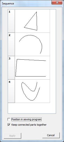
72 5-26 DA-CAD Interpolation With the function Interpolation you can manage that the stitches will be uniformly distributed over the selected seam sections An end or start point of a seam section represents not necessarily a stitch no interpolation with interpolation Note: In case of the interpolation corner stitches can be disappear Work flow: Interpolation 1 The seam sections must first be selected in the drawing box 2 Click on the Interpolation 5-5 icon in the "Scaling and Moving" tool box Calculation the stitches starts automatically Work flow: No interpolation 1 The seam sections must first be selected in the drawing box 2 Click on the Interpolation 5-5 icon in the "Scaling and Moving" tool box 3 Calculation the stitches starts automatically 5116 Sequence window It is possible to change the sequence of the seam sections
73 Editing seam programs Note: There are two different ways: a Connected seam sections stay connected They will be moved together b You can change the position of every seam section Beispiel einer Sequenz von Nahtabschnitten Work flow: Change sequence 1 In the Icon menu bar, 3-13 click on the Sequence 1 The sequence window is then opened: icon 5-27

74 5-28 DA-CAD 5000
75 Editing seam programs Choose the position number by click and hold left mouse button and move to the new position:
76 5-30 DA-CAD You set the new position by release the mouse button:
77 Editing seam programs 4 With apply you close the sequence window Calculation the new position starts automatically: 5 You can cancel this window without any changes to the seam section by clicking on Cancel 5-31
78 DA-CAD 5000 Edit a support point Note: Support points can be edited in the "Support point" 3-13 view A support point must first be selected or activated in the drawing box 5-34 before it can be edited These seam sections are described using support points including start and end points, as well as certain shapes (such as circular segments or spline curves) and additional mid-support points In the drawing box of the "Support points" view, these are shown with different colours: 1 Start point green 2 End point red 3 Mid-support point blue 4 Selected support point yellow Support points are shown as X and Y coordinates (in millimetres) in the table The type of seam section 5-4 is also shown If two seam sections are connected to each other, the cells which show their coordinates are connected and shown in red[1]
 : Additional support points can be inserted for the seam section types line and spline For seam section consisting of multiple lines, it is")
79 Editing seam programs 5-33 A variety of functions are available for editing the selected support points: Move Delete Insert 5-36 : the selected support point can be moved in any direction : Support points can be deleted (with a few restrictions) : Additional support points can be inserted for the seam section types line and spline For seam section consisting of multiple lines, it is possible to separately configure sections 5-46 individual
80 DA-CAD 5000 Selection of support points Note: Support points can only be selected in the Support point 3-15 view There are two ways to activate a support point: you can mark it in the drawing box, or you can select it in the values table Work flow: Selection of a support point in the drawing box 1 Position the mouse cursor over the desired support point 2 Select the support point with the left mouse button 3 The selected support point will then be shown in yellow 4 If the table view 3-13 is activated, then the X value for this support point is selected 5 In the case of a seam section with connected lines, when a support point is selected the individual section is simultaneously activated whose end point is this support point ( Configuration of individual sections 5-46 ) The individual section is then shown with a dark red line

81 Editing seam programs 5-35 Note: If the chosen coordinate represents more than one support point, a drop down menu appear, where you can choose one or all points Meaning: 1/3/End point: End point of the 3 part of the 1 seam section Work flow: The selection of a support point in the table Note: In order to work with the table, the table view must be activated in the Icon menu bar on the Table icon 3-13, by clicking 1 Select the appropriate cell in the table containing the X/Y coordinates for the desired support point 2 The selected support point will then be shown in yellow in the drawing box 3 In the case of a seam section with connected lines, when a support point is selected the individual section is simultaneously activated whose end point is this support point ( Configuration of individual sections 5-46 ) The individual section is then shown with a dark red line
82 DA-CAD 5000 Moving a support point It is possible to move a support point: in the drawing box 5-36 or by using the values table 5-36 Note: A new calculation for the seam section is required when a support point is moved This causes all stitch-related action points and all stitch reworking operations to be lost Work flow: Moving a support point in the drawing box 1 You must first select the support point that you want to move in the drawing box Position the mouse cursor over the desired support point 3 Press and hold theleft mouse button 4 Press down on the left mouse button and move the mouse in order to move the selected support point 5 Release the left mouse button when the desired position is reached 6 The seam section is then automatically moved Work flow: Moving a support point in the table 1 Activate the X/Y coordinates of the support point that you wish to move in the table by double clicking on them 2 Enter the desired values and confirm by pressing Return 3 The support point is then automatically moved and this is shown graphically
83 Editing seam programs Delete a support point It is possible to delete a support point: in the drawing box 5-37 or by using the values table 5-37 Depending on the type of seam section, the following rules are relevant: Line Circular segment Spline curve As long as more than one individual section exists, any point from the seam section can be deleted No support point can be deleted Instead you must delete the entire seam section 5-24 Start and end points can not be deleted As long as more than one mid-support points exist, any mid-point can be deleted Note: A new calculation for the involved seam section or partial section is required after deleting a support point This causes all stitch-related action points and all stitch reworking operations to be lost Work flow: Deleting a support point in the drawing box 1 You must first select the support point that you want to delete in the drawing box 2 Click on the Delete 5-34 icon to delete the selected support point 3 Alternatively, the selected support point can be deleted by using the Del key 4 The change is then automatically carried out in the seam program Work flow: Deleting a support point in the table 1 Activate the X/Y coordinates of the support point that you wish to delete in the table by double clicking on them 2 Click on the Delete icon to delete the selected support point 3 Alternatively, the selected support point can be deleted by using the Del key 4 The change is then automatically carried out in the seam program
84 DA-CAD 5000 Insert Note: The insertion of support points is only supported for seam sections which are types line or spline There are two basic options for inserting a support point in the table: before after the selected support point the selected support point The possibilities available depend on the selected support point, as follows: selected support point Start Middle End Depending on the type of insertion, the newly inserted support point is placed: Before: halfway between the selected support point and the support point that is positioned before it After: halfway between the selected support point and the support point that is positioned after it The newly inserted support point can then be edited (for example, moved) Note: A new calculation for the seam section is required when a support point is inserted This causes all stitch-related action points and all stitch reworking operations to be lost Work flow: Insert before the selected support point 1 Click on the X/Y coordinate value of the support point in the table to activate the location before which a support point will be inserted 2 Click on the Insert before the selected support point icon to insert an additional support point on the seam section before 3 The change is then automatically carried out in the seam program and a new calculation of the seam section is performed 4 If desired, the new support point can now be moved 5-36
85 Editing seam programs 5-39 Work flow: Insert after the selected support point 1 Click on the X/Y coordinate value of the support point in the table to activate the location after which a support point will be inserted 2 Click on the Insert after selected support point icon to insert an additional support point on the seam section after the 3 The change is then automatically carried out in the seam program and a new calculation of the seam section is performed 5 If desired, the new support point can now be moved 5-36


86 DA-CAD 5000 Connect With this function you can connect two seam sections This connection will be represented by an additional line Note: You can only connect an end point of a section with a start point of an other seam section connecting seam section 1 with section 2: Note: If two not sequential seam sections are connected, the sequence of the seam sections changes by connecting All sections,which follow that the new connected section, are shifted
87 Editing seam programs Ex: seam section sequence: connect with : connect with : Work flow: Connecting seam sections 1 The end point of one seam sections must first be selected in the drawing box
88 5-42 DA-CAD Click on the Connecting icon 3 Choose with the cursor the start point of one seam section If this start point is permissible, the cursor changes its appearance: 4 Confirm this point with the left mouse buttonconnecting the two seam sections is then carried out automatically 5 Cancel: You can cancel the connecting process at any time by clicking on the right mouse button

89 Editing seam programs Move & Connect With this function you can connect two seam section by moving the second section to the connecting point Note: You can only connect an end point of a section with a start point of an other seam section connecting seam section 1 with section 2:
90 5-44 DA-CAD 5000 Note: If two not sequential seam sections are connected, the sequence of the seam sections changes by connecting (s Connect 5-40 ) Work flow: Connecting seam sections 1 The end point of one seam sections must first be selected in the drawing box 2 Click on the Move & Connecting icon Choose with the cursor the start point of one seam section If this start point is permissible, the cursor changes its appearance: 4 Confirm this point with the left mouse buttonconnecting the two seam sections is then carried out automatically 5 Cancel: You can cancel the connecting process at any time by clicking on the right mouse button
91 Editing seam programs 5-45

92 DA-CAD 5000 Divide seam sections There is a possibility of separating connected seam sections so that the separate sections can be worked on independently Note: Seam sections can only be divided on start or end points Work flow: Divide seam sections 1 You must first select the support point that you want to divide in the drawing box 2 In the tool menu bar click on the Divide 5-34 Icon 3 The separation is made automatically Now there are two seam sections These can be worked on separately before divide: after divide: 528 Configuration of individual sections Note: This chapter is only relevant for seam sections which are of type Line If a seam section consists of multiple lines, each individual section can be assigned its own
93 Editing seam programs 5-47 configuration values Thus, within a seam section, it is possible to change the stitch length or to sew one section with a zigzag pattern Note: All stitch-related action points for the individual section will be lost if a new calculation is required because of the configuration of this section Work flow: Configuring individual sections 1 The end point of the individual section to be configured must first be selected in the drawing box The individual section is then shown with a dark red line 2 In the Icon menu bar, 3-13 click on the Seam section configuration 3 The configuration window for seam sections 7-8 is then opened: icon 5-34

94 5-48 DA-CAD Make the required changes in this window ( Config window description 7-8 ) and then end the data entry by clicking on OK A new calculation will be automatically carried out if required 5 It is possible to cancel at any time 6 Undo resets all values back to what they were before the window was opened 7 By clicking on Default, all parameters are reset to the values of the default parameters 7-4
95 Editing seam programs Edit stitch or stitches Note: Stitches can be edited in the "Stitches" 3-13 view Stitches must first be selected or activated in the drawing box 5-50 before they can be edited When drawing seam sections, stitches are automatically shown according to the pre-set stitch length It is possible to edit these stitches The following functions are available for editing the selected stitches: Move 5-53 Delete Insert : individual stitches or a group of stitches can be moved : individual stitches or a group of stitches can be deleted : stitches can be inserted Edit action point be edited 5-56 : action points can be attached to individual stitches and these action points can Stitches are shown as filled circles: green non-activated stitch black activated stitch Note: If a seam section needs to be recalculated (for example, after scaling), then the stitches in this seam section must be regenerated All stitching work performed on this seam section up to this point are then lost and must be redone

96 DA-CAD 5000 Selection of stitches Note: Stitches can only be selected in the Stitch 3-15 view There are several ways to activate stitches First you must determine if you are selecting a single stitch or multiple sequential stitches: Click directly on the desired stitch Pull out a border around the desired seam stitch or stitches Select one or more stitches in the values table 5-51 Work flow: Selecting a stitch directly 1 Position the mouse cursor over the desired stitch 2 Select the stitch with the left mouse button 3 The selected stitch is then shown in black 4 If the table view 3-13 is activated, then the X value for this stitch is selected Note: If the chosen coordinate represents more than one stitch, a drop down menu appear, where you can choose one or stitches Meaning: 2/1/13:13 stitch of the 1 part of the 2 seam section Work flow: Selecting stitches by pulling out a border
97 Editing seam programs 5-51 Note: The selected stitches must be completely enclosed by the extended border 1 Position the mouse cursor over any point outside of the stitch that you wish to activate 2 Press and hold the left mouse button 3 A border will be extended when you press the left mouse button 4 The left mouse button can be released when the border encloses all of the desired stitch or stitches 5 All of the stitches are activated when they are completely enclosed by the border All activated stitches are shown in black Work flow: The selection of a stitch in the table Note: In order to work with the table, the table view must be activated in the Icon menu bar on the Table icon 3-13, by clicking 1 Select the appropriate cell in the table containing the X/Y coordinates for the desired stitch 2 The selected stitch will then be automatically shown in black in the drawing box Work flow: The selection of a stitch in the table Note: In order to work with the table, the table view must be activated in the Icon menu bar on the Table icon 3-13, by clicking 1 Position the mouse cursor in the "No" column, at the beginning of the range that you wish to activate for the desired stitches 2 Press and hold the left mouse button 3 The proper stitches are then marked by making an up or down motion with the left mouse button pressed down 4 Release the left mouse button when all desired stitches in the table have been marked 5 The selected stitches will then automatically be shown in black in the drawing box
98 5-52 DA-CAD 5000
99 Editing seam programs Move stitch When moving a stitch, it is important to determine the following: one stitch is activated: it is possible to move in the drawing box and in the table multiple stitches are selected: it is possible to move only in the drawing box Work flow: Move within the drawing box 1 You must first select the stitches that you want to move in the drawing box or table Position the mouse cursor over a marked stitch 3 Press and hold the left mouse button 4 Press down on the left mouse button and move the mouse in order to move the selected stitches 5 Release the left mouse button when the desired position is reached 6 The stitches are then automatically moved Work flow: Moving by making changes to the table Note: The table makes use of two coordinate systems: absolute coordinates relative coordinates 1 Activate the X/Y coordinates of the stitch that you wish to move in the table by double clicking on them 2 Enter the desired values and confirm by pressing Return 3 The stitch is then automatically moved and this is shown graphically Note: Remember that if a change is made to the relative coordinates in the table, this leads to a change in the absolute coordinates of the subsequent stitches in this seam section
100 DA-CAD 5000 Delete stitch It is possible to delete a stitch: in the drawing box 5-37 or by using the values table 5-37 Work flow: Deleting stitches in the drawing box 1 You must first select the stitch that you want to delete in the drawing box 2 Click on the Delete 5-34 icon to delete the selected stitch 3 Alternatively, the selected stitch can be deleted by using the Del key 4 The change is then automatically carried out in the seam program Work flow: Deleting a stitch in the table 1 You must first select the stitches that you want to delete in the table 2 Click on the Delete 5-5 icon to delete the selected stitch 3 Alternatively, the selected stitch can be deleted by using the Del key 4 The change is then automatically carried out in the seam program
101 Editing seam programs Insert stitch There are two basic options for inserting a stitch in the table: before after the selected stitch, the selected stitch Depending on the type of insertion, the newly inserted stitch is placed: Before: halfway between the selected stitch and the stitch that is positioned before it After: halfway between the selected stitch and the stitch that is positioned after it The stitch can then be edited or, for example, moved Work flow: Insert before the selected stitch 1 Click on the X/Y coordinate value of the stitch in the table to activate the location before which a stitch will be inserted 2 Click on the Insert before selected stitch icon to insert an additional stitch on the seam section before the 3 If desired, the new stitch can now be moved 5-53 Work flow: Insert after the selected stitch 1 Click on the X/Y coordinate value of the stitch in the table to activate the location after which a stitch will be inserted 2 Click on the Insert after stitch icon to insert an additional stitch on the seam section after the selected 3 If desired, the new stitch can now be moved 5-53
102 DA-CAD 5000 Edit action point It is possible to assign technology points to each stitch The maximum number of possible technology points and the type of allowed technology points both depend on the machine class In the case where no machine class has been selected, all known technology points should first be assigned Machine-specific criteria are then automatically taken into account during the machine-classspecific data transfer 6-3 process The stitch-specific technology point list can be edited by inserting, changing and deleting technology points If you wish to delete all technology points in a seam section, a seam section editing function is available for this purpose ( Delete all technology points 5-24 ) The following can be determined for the technology points: technology point with a value: changes to rotational speed or thread tension, setting a designated output, querying a designated input, etc technology point without a value: cut, thread burner on, lower clamp, etc Note: In order to work with the table, the table view must be activated in the Icon menu bar on the Table icon 3-13, by clicking Work flow: Editing an technology point 1 You must first select the stitch where you want to edit the technology point list This can be selected in the drawing box or table Double click with the left mouse button in the table's technology point column It is not important which technology point column is clicked on 3 The "Edit technology point" menu then opens automatically
 5 Click on OK to leave the menu The new technology point list is now automatically valid and")

103 Editing seam programs You can add or delete the desired technology points, or change technology point values ( Description of technology point editing window 7-23 ) 5 Click on OK to leave the menu The new technology point list is now automatically valid and the current technology points are shown in the table 6 You can click on the Cancel button to leave the menu without making any changes If at least one technology point is assigned to a stitch, then this is indicated in the drawing box by a technology-point-list icon:
104
105 Part Data transfer to the machine VI
106
107 Data transfer to the machine Data transfer to the machine This capital describes how to transfer the seam program from the PC to the machine Two types of data media are supported, depending on the class of the machine: Dongle 6-3 : a Dürkopp Adler memory stick for connecting with the DAC3 and DAC4 control units USB memory stick 6-14 : a standard USB flash drive for connecting with the USB interface on the machine (eg, BFT) Note: The desired machine class must be defined before writing to a data storage medium ( machine class 3-11 ) Setting the The seam program which is to be written to the data medium must first be saved on the PC It is not possible to save a newly drawn seam program to the data medium which has not first been saved to the PC The generic format of the seam program is converted to a machine-specific format and then written to the data medium 61 Dongle Note: The PC must have a serial interface available This interface must be configured with the menu option Settings > Interface 3-11 The dongle must be first be formatted according to the machine class before you can work with it The following functions are available when working with a dongle: Format 6-4 : Class-specific format of dongle Read contents Save : Read the dongle's table of contents : Save the seam program to the dongle


108 DA-CAD 5000 Format The dongle must be first be formatted according to the machine class before you can work with it Note: The PC must have a serial interface available This interface must be configured with the menu option Settings > Interface 3-11 Work flow: Formatting a dongle 1 Plug the dongle into the serial port 2 Select the menu choice Data transfer > Dongle > Format 3 The formatting window in then opened: 4 Select the class and sub-class You can also assign a name to the dongle 5 Click on Format and then confirm the confirmation dialogue in order to start the format process 6 Click on Cancel or No in the confirmation dialogue in order to cancel the window without making any change 7 The following error message appears if no dongle can be found (for example, if not present or incorrectly inserted):

109 Data transfer to the machine Read contents Dongles are not only used for transferring seam programs between PCs and machines They can also be put to use as boot dongles This then contains the machine program This function is used to read and display the content of a dongle Work flow: Read the dongle's contents 1 Plug the dongle into the serial port 2 Select the menu choice Data transfer > Dongle > Contents 3 An information screen appears, depending on the machine class and type of dongle: 31 Machine classes with a fixed memory capacity (for example, class 511):
: Here you can sort according to name, size or date 33 Boot dongle")

110 6-6 DA-CAD Machine classes with freely allocated memory management (for example, class 910): Here you can sort according to name, size or date 33 Boot dongle connected: 4 Click on Close in order to re-close this screen 5 The following error message appears if no dongle can be found (for example, if not present or incorrectly inserted):

111 Data transfer to the machine Saving to a dongle This function enables you to save seam programs on a dongle Depending on the class, there are two methods for saving which you should be aware of: Machine classes with fixed memory capacity 6-7 : A save destination must be specified Machine classes with freely allocated memory management determine what storage space is free 6-9 : The program can automatically Note: In order to write to a dongle, the dongle must first be formatted according to the machine class in use Work flow: Saving on a dongle for machine classes with fixed memory capacity 1 Plug the dongle into the serial port 2 Select the menu choice Data transfer > Dongle > Save (PC Dongle) 3 A window is opened for saving to the dongle 4 Define the required memory location by clicking on the desired location

112 6-8 DA-CAD Click on Browse in order to open the standard Windows window for file selection Select the desired seam program and close the window The is activated after a file has been selected and a memory location has been specified This icon is deactivated if either of these criteria has not been fulfilled 6 Click on the dongle icon The desired file is then transferred to a class-specific format and written to the Note: Files with identical names can be archived more than once 7 When the save process is over, the contents are redisplayed 8 Go back to step 4 if you need to save another file to the dongle 9 Exit the window by clicking on Close 10The following error message appears if no dongle can be found (for example, if not present or incorrectly inserted):
113 Data transfer to the machine 6-9 Work flow: Saving on a dongle for machine classes with freely allocated memory management 1 Plug the dongle into the serial port 2 Select the menu choice Data transfer > Dongle > Save (PC Dongle) 3 A window is opened for saving to the dongle Here you can sort according to name, size or date 4 Click on Browse in order to open the standard Windows ; window for file selection Select the desired seam program and close the window The icon is activated after a file is selected The icon is not activated when no file has been selected: 5 Click on the dongle icon The desired file is then transferred to a class-specific format and written to the Note: Files with identical names can be archived more than once There is no validation and existing files with the same name are not overwritten
114 6-10 DA-CAD When the save process is over, the contents are redisplayed 7 Go back to step 4 if you need to save another file to the dongle 8 Exit the window by clicking on Close 9 The following error message appears if no dongle can be found (for example, if not present or incorrectly inserted):

115 Data transfer to the machine Load A sewing file can be loaded from the dongle again, in order to be able to work on it with this software "DA-CAD 5000" further Note: When loading from the dongle, the seam program must be converted into the general formatmachineclass-dependently there can be information losses, because the seam sections consist only single stitches Work flow: Load from Dongle 1 Plug the dongle into the serial port 2 Select the menu choice Data transfer > Dongle > Load (Dongle PC) 3 A window is opened for deleting sewing files on the dongle In the contents window all programs contained on the dongle are represented Classes with free storage administration (eg Class 910) can be sorted additionally according to name, size or date 4 Specify the desired program with Click in the contents window 5 If a file were selected, the switch is activated Otherwise the switch is deactivated: 6 Click on button in order to open the standard Windows window for file selection The desired file is stored on the PC (converted into the PC-specific format) 7 Go back to step 4 if you need to load another file from the dongle 8 Exit the window by clicking on Close 9 The following error message appears if no dongle can be found (for example, if not present or
116 6-12 DA-CAD 5000 incorrectly inserted):


117 Data transfer to the machine Delete There is the possibility of deleting seam programs on the dongle: Work flow: Delete on the Dongle 1 Plug the dongle into the serial port 2 Select the menu choice Data transfer > Dongle > Delete 3 A window is opened for deleting sewing files on the dongle In the contents window all programs contained on the dongle are represented Classes with free storage administration (eg Class 910) can be sorted additionally according to name, size or date 4 Specify the desired program with Click in the contents window 5 If a file were selected, the switch 6 Click on button updated is activated Otherwise the switch is deactivated: The selected file is deleted Subsequently, the representation of contents is 7 Go back to step 4 if you need to delete another file on the dongle 8 Exit the window by clicking on Close 9 The following error message appears if no dongle can be found (for example, if not present or incorrectly inserted):
118 DA-CAD 5000 USB memorystick (flash drive) Note: A USB port must be available on the PC The following functions are available when working with a USB flash drive: 621 Save 6-14 : Save the seam program to the USB flash drive Load 6-16 : Load (read in) the seam program from the USB flash drive Saving to a USB "stick" flash drive This function enables you to save seam programs on a USB flash drive The generic format of the seam program is converted to a machine-specific format and then written to the USB flash drive The program keeps its name during this process Only the file extension is changed The file extension indicates that the format and file are specific to the machine class: *fnpxxx, where xxx indicates the class number, for example 911 *fnp911 Note: The correct machine class must first be defined in the menu Settings > Machine class write to the USB flash drive 3-11 in order to Work flow: Saving to a USB flash drive 1 Insert the flash drive into a USB port 2 Select the menu choice Data transfer > USB flash drive > Save (PC USB) 3 A window is opened for saving to the USB flash drive

119 Data transfer to the machine Define the target (USB) drive: Click on Browse in order to open the standard Windows window for selecting a drive Select the desired drive and close this window 5 Two possibilities exist of specifying which program is to be saved: a Current Program: The seam program on the current drawing board is stored b File select: I Select source files: Click on Add to open the standard Windows file selection window Select the desired seam program and close the window II All selected seam programs are then displayed in a list A file from the same directory can only be added once III If you need to delete one or more files from the list, mark them with a mouse click and click on Delete 6 Click on Save in order to convert the selected seam program to a machine-specific format and then save it to the USB flash drive This window is automatically closed after the save operation is successfully completed 7 You can click on the Cancel button to leave the window without saving

120 DA-CAD 5000 Load from a USB flash drive Seam programs can be reloaded from a USB flash drive and then edited with the "DA-CAD 5000" software During the loading, the seam program is reconverted into the generic format In contrast to loading from a dongle, there is no loss of information when loading from USB Work flow: Reading from the USB flash drive 1 Insert the flash drive into a USB port 1 Select the menu choice Data transfer > USB flash drive > Load (USB PC) 2 A window is opened for saving to the USB flash drive 3 Select USB source files: Click on Add to open the standard Windows file selection window Select the desired seam program and close the window 4 All selected seam programs are then displayed in a list A file from the same directory can only be added once 5 If you need to delete one or more files from the list, mark them with a mouse click and click on Delete 6 Define the target drive: Click on Browse in order to open the standard Windows window for selecting a drive Select the desired drive and close this window
121 Data transfer to the machine Click on Save in order to convert the selected seam program and then save it to the speficied location on the PC This windows closes automatically after the file has been saved successfully All loaded programs are displayed automatically in separate windows 8 You can click on the Cancel button to leave the window without saving
122
123 Part Input windows VII
124
125 Input windows 7 Input windows The following chapter describes the different input windows This is divided into input windows for: Settings Editing : Machine class, default parameters, etc of seam sections: move, scale, etc Settings The editing windows for the following settings are described in this section: Default parameters 7-4 Configuring seam sections 7-8 Selecting the machine class Selecting the language Configuring the serial interface port Setting the grid lines 7-13 Selecting a background image

126 DA-CAD 5000 Default parameters window The default parameters input window is divided into four tabs Tabbed sections three and four are only visible if a zigzag seam needs to be sewn Tab 1: General Parameter Description Stitch length Length between two needle entry points, in millimeters The length of a seam section should be divided into sections of this length Rotational speed The rotational speed that will be used to sew the seam program This is the starting speed It is specified in revolutions per minute Selected option Description Linear (without zigzag) The seam sections are calculated linearly between the support points When this is selected, the third and fourth tabs are not visible Zigzag The seam section will be executed as a zigzag When this is selected, the third and fourth tabs are visible

127 Input windows 7-5 Tab 2: Model specific Machine specific parameters can be set here If the selected machine class does not support a parameter, then the parameter is greyed-out and can not be changed Parameter Description Thread tension The thread tension value, in percent, that will be used to sew the seam program Stroke height The height of the stroke motion made by the oscillating sewing feet during the sewing process Setting range: 1 to 20 Stroke position The position of the sewing foot in the lowered position Setting range: 1 to 10 0 = smallest clearance space to material 10 = largest clearance space to material Empty run speed The speed used for non-sewing movements This is specified as a percent of the sewing speed

128 7-6 DA-CAD 5000 Tab 3: Zigzag (1): Only shown when Zigzag is selected in Tab 1 Symmetrical width Description yes The zigzag will be drawn symmetric to the seam section line One value is given for the total width no The zigzag is drawn with two different widths: one each for the left and right side of the seam section line Separate values for the left and right side widths can be specified Width Description Sym width The total width of the zigzag which is situated symmetrical to the seam section line (shown in diagram as B) Activated if Symmetrical width is selected Left width The width of the zigzag on the left side (shown in diagram as l) Activated if Symmetrical width is not selected Right width The width of the zigzag on the right side (shown in diagram as r) Activated if Symmetrical width is not selected Parameter Length of zigzag The length of a zigzag (consisting of two zigzag paths) (shown in the diagram as L) Number of stitches The number of stitches that are present on one leg of the zigzag (shown in the diagram as 4)

129 Input windows 7-7 Tab 4: Zigzag (2): Only shown when Zigzag is selected in Tab 1 Zigzag shapes Description V shape The zigzag has a V shape N shape The zigzag has an N shape Start ZZ shape Description Right The first zigzag leg will start on the right side V shape: Left N shape: The first zigzag leg will start on the left side V shape: ;N shape: Stitch position Description First stitch Select the position at which the first stitch will be executed: left, middle, right Last stitch Select the position at which the last stitch will be executed: left, middle, right
 The seam sections are calculated linearly between the support points When this is selected, the second and third")
130 DA-CAD 5000 Configuration window for current seam section The seam sections configuration window is divided into four tabs Tabbed sections two and three are only visible if a zigzag seam needs to be sewn Tab 1: General Selected option Description Linear (without zigzag) The seam sections are calculated linearly between the support points When this is selected, the second and third tabs are not visible Zigzag The seam section will be executed as a zigzag When this is selected, the second and third tabs are visible Selected option Description Stitch length Length between two needle entry points, in millimeters The length of a seam section should be divided into sections of this length Only activated if Linear has been selected Number Number of stitches that make up a seam section The number of sections shown is (gap - 1) Only activated if Linear has been selected Click on Thread cutter before non-sewing movement adds this action point before each non-sewing movement of the chosen outlines and is then shown by the symbol

131 Input windows 7-9 Tab 2: Zigzag (1): Only shown when Zigzag is selected in Tab 1 Symmetrical width Description yes The zigzag will be drawn symmetric to the seam section line One value is given for the total width no The zigzag is drawn with two different widths: one each for the left and right side of the seam section line Separate values for the left and right side widths can be specified Width Description Sym width The total width of the zigzag which is situated symmetrical to the seam section line (shown in diagram as B) Activated if Symmetrical width is selected Left width The width of the zigzag on the left side (shown in diagram as l) Activated if Symmetrical width is not selected Right width The width of the zigzag on the right side (shown in diagram as r) Activated if Symmetrical width is not selected Parameter Length of zigzag The length of a zigzag (consisting of two zigzag paths) (shown in the diagram as L) Number of stitches The number of stitches that are present on one leg of the zigzag (shown in the diagram as 4)

132 7-10 DA-CAD 5000 Tab 3: Zigzag (2): Only shown when Zigzag is selected in Tab 1 Zigzag shapes Description V shape The zigzag has a V shape N shape The zigzag has an N shape Start ZZ shape Description Right The first zigzag leg will start on the right side V shape: Left N shape: The first zigzag leg will start on the left side V shape: N shape: Stitch position Description First stitch Select the position at which the first stitch will be executed: left, middle, right Last stitch Select the position at which the last stitch will be executed: left, middle, right

133 Input windows 7-11 Tab 4: Action point before first stitch It is possible to execute an action point before sewing begins on the seam section These actions points can be defined here Click on the "TP before 1 stitch" button to open the Editing action points window is used for adding, changing or deleting action points If at least one action point has been assigned, this is then shown by the 7-23 input window This symbol


134 DA-CAD 5000 Machine class This window is used to specify the machine class and the sewing field size 714 Selection menus Description Class A list of all the machine classes support by this software It is also possible to choose no class Sewing field All the available sewing field sizes for the selected class are listed here Language This window is used to specify a language for the software program The language selection goes into effect immediately Selection menus Description Deutsch The software language is German English The software language is English


135 Input windows Serial interface This window is used to specify the serial port that will be used when working with a dongle Additional configuration is not required 716 Selection menus Description COMx A list of all available serial ports on the PC Grid lines This window is used for configuring the grid lines for all windows symmetrical Description yes Grid lines will be displayed using identical intervals for both the X and Y axes no Different values can be given for the intervals in the X and Y axes Grid line interval Description X Grid line interval for X axis, in millimetres Y Grid line interval for Y axis, in millimetres Activated only if symmetrical is selected

136 7-14 DA-CAD 5000 Show Description yes Grid lines will be shown using the specified interval and the selected colour no No grid lines will be shown Colour Description Selection of the grid line colour 717 Background image Here you can choose a background image for the current window Only BMP and JPG files can be used as background images Click on Browse to open the standard Windows file selection window Select the desired background image and close the window Change proportionally yes no Description When the width is changed, the height is automatically changed proportionally The width and height can be specified separately This can lead to distortion of the image Dimensions Description Width The width of the background image Height The height of the background image Activated only if change proportionally is not selected

137 Input windows 72 Edit The following editing windows are described in this section: Rotate 7-15 Scale 7-17 Move 7-19 Generate an equidistant counterpart Duplicate 7-22 Edit an action point Rotate Window to rotate selected sewing sections It can be selected: direction of rotation, angle of rotation, position of the centre of rotation Configuration of the direction and the angle of rotation: Selection Description 90 left Rotate the selected sewing sections 90 anticlockwise 90 right Rotate the selected sewing sections 90 clockwise 180 Rotate the selected sewing sections 180 Exat Angle of rotation can be assigned freely 7-15
138 7-16 DA-CAD 5000 Exact is activated: Angle Description 0359 Angle of rotation Selection Description Rotate the selected sewing sections anticlockwise Rotate the selected sewing sections clockwise Configuration of the position of the centre of rotation: Selection Description Centre of contour It is turned around the centre of the selected sewing sections Arbitrary point The position of the centre of rotation can selected arbitrary Arbitrary point is activated: Selection Description X X- Coordinate value of the centre of rotation Y Y- Coordinate value of the centre of rotation
139 Input windows Scale The window for scaling (resizing) the selected seam sections Selection Description Percent The seam sections are resized based on a percentage When this option is selected, the scaling percent fields are activated and the absolute size fields are greyed out Size Seam sections are resized based on an absolute value measurement When this option is selected, the absolute size fields are activated and the scaling percent fields are greyed out Percent activated: Symmetrical Description yes When the X value is changed, the Y value automatically changes by the same percentage to avoid any distortion of the seam section no Different percentage values can be specified for the X and Y axes Distortion of the seam section is not ruled out Dimensions Description X Width of the selected seam sections, in percent Y Height of the selected seam sections, in percent Activated only if symmetrical is not selected
140 7-18 DA-CAD 5000 Size activated: Symmetrical Description yes When the width is changed, the height is automatically changed proportionally no The width and height can be specified separately This can lead to distortion of the seam section Dimensions Description Width Width of the selected seam sections Height Height of the selected seam sections Activated only if symmetrical is not selected Selection Description Stitch length Previous stitch length of the seam section is maintained Number of stitches Previous stitch count for the seam section is maintained: The stitch length will then change New stitch length Specify a new stitch length, in millimetres
 Relatively activated: Dimensions Description X The distance value that the selected seam sections")
141 Input windows Move Window for moving the selected seam sections Selection Description Relatively Move the seam sections using the specified X and Y directional values Absolutely Move the start point of the first selected seam section to the specified coordinates (X and Y value pair) Relatively activated: Dimensions Description X The distance value that the selected seam sections should be moved (along the X axis) Y The distance value that the selected seam sections should be moved (along the Y axis) Absolutely activated: Dimensions Description X The X coordinate value of the start point of the first seam section in the selected seam sections Y The Y coordinate value of the start point of the first seam section in the selected seam sections

142 DA-CAD 5000 Generate an equidistant counterpart This window is used for settings the parameters needed generate an equidistant counterpart for the selected seam sections Parameter Description Number The number of equidistant counterparts that should be generated Range: 1 5 Gap Gap between the first counterpart to the seam section (and between the other equidistant counterparts), in millimeters Alignment Description Left Relative to the seam direction, the counterpart will be created on the left side Right Relative to the seam direction, the counterpart will be created on the right side Maintain Description Stitch length Previous stitch length of the seam section is maintained Number of stitches Previous stitch count for the seam section is maintained: The stitch length will then change
StickFont Editor v1.01 User Manual. Copyright 2012 NCPlot Software LLC
 StickFont Editor v1.01 User Manual Copyright 2012 NCPlot Software LLC StickFont Editor Manual Table of Contents Welcome... 1 Registering StickFont Editor... 3 Getting Started... 5 Getting Started...
Fire Scene 6. Tip Sheet
 Fire Scene 6 Tip Sheet Fire Scene 6 All rights reserved. No parts of this work may be reproduced in any form or by any means - graphic, electronic, or mechanical, including photocopying, recording, taping,
Laser Machine User Manual:
 Laser Machine User Manual: OPERATOR ( EasyCut / LaserCut version 5.3 ) v1.0 CTR Laser Machine Operator Manual ( EasyCut version 5.3 ) ~ version 1.0 1 CONTENTS Section 1: Tutorials...5 1.1. How to Cut with
FastTrack Schedule 10. Tutorials. Copyright 2010, AEC Software, Inc. All rights reserved.
 FastTrack Schedule 10 Tutorials FastTrack Schedule Tutorials Version 10.0.0 by Carol S. Williamson AEC Software, Inc. With FastTrack Schedule 10, the new version of the award-winning project manager,
XPEL DAP SUPPORT. DAP Tool List & Overview DESCRIPTION ICON/TOOL (SHORTCUT)
") Pointer (S) Left-click on individual entities to add them to the current selection (selected entities will turn red). If the entity selected is a member of a group, the entire group will be added to the
Pointer (S) Left-click on individual entities to add them to the current selection (selected entities will turn red). If the entity selected is a member of a group, the entire group will be added to the
Tutorial 3: Constructive Editing (2D-CAD)
") (2D-CAD) The editing done up to now is not much different from the normal drawing board techniques. This section deals with commands to copy items we have already drawn, to move them and to make multiple
(2D-CAD) The editing done up to now is not much different from the normal drawing board techniques. This section deals with commands to copy items we have already drawn, to move them and to make multiple
Graphics course. W.Theiss Hard- and Software for Optical Spectroscopy Dr.-Bernhard-Klein-Str. 110, D Aachen Wolfgang Theiss
 Graphics course W.Theiss Hard- and Software for Optical Spectroscopy Dr.-Bernhard-Klein-Str., D-578 Aachen Phone: (49) 4 5669 Fax: (49) 4 959 E-mail: theiss@mtheiss.com Web: www.mtheiss.com Wolfgang Theiss
Exploring the Workspace
 Exploring the Workspace The illustration above shows a typical Create and Cut screen when first loading the software. See the coordinating sections below for an explanation of each shortcut button. Design
Page Fault Monitor. by Software Verify
 Page Fault Monitor by Software Verify Copyright Software Verify Limited (c) 2015-2017 MAP File Browser MAP file contents inspector by Welcome to the MAP File Browser software tool. MAP File Browser is
Phone: Fax: Web: -
 Table of Contents How to Use GTWIN 1. Functions of Parts...1-1 1.1 Screen Names of GTWIN... 1-2 1.2 Menu Bar... 1-3 1.3 Toolbar... 1-4 1.4 Screen Manager... 1-6 1.5 Parts Library... 1-7 1.6 Graphicbar...
6D Embroidery Software - Pretty Paisleys
 6D Embroidery Software - Pretty Paisleys By: Soni Grint Learn what type of picture is best to use for a background while digitizing these pretty paisleys. Adjust the picture as needed before placing stitches.
MIMAKI ENGINEERING CO., LTD.
 For Windows XP/Windows 2000 Cutting Application Software SimpleCut Operation Manual MIMAKI ENGINEERING CO., LTD. D201463 Contents Introduction 1 About this Manual 2 Chapter 1 Installation Procedure 3
SUNLITE is a trademark of Bruno Nicolaudie. WINDOWS is a trademark of the MICROSOFT CORPORATION. All rights reserved. No parts of this work may be
 SUNLITE is a trademark of Bruno Nicolaudie. WINDOWS is a trademark of the MICROSOFT CORPORATION. All rights reserved. No parts of this work may be reproduced in any form or by any means - graphic, electronic,
Using SymPrint to Make Overlays, Templates & More...
 Welcome to SymPrint SymPrint is an easy-to-use tool for creating communication overlays, worksheets, classroom activities and more using a modern toolbar and common-sense interface modeled after the programs
Roof Designer USER S GUIDE
 Roof Designer USER S GUIDE Roof Designer-1 Roof Designer-2 Roof Designer The Roof Designer makes it easy to define and place custom roofs in your project. You can start the Roof Designer independently,
GstarCAD Complete Features Guide
 GstarCAD 2017 Complete Features Guide Table of Contents Core Performance Improvement... 3 Block Data Sharing Process... 3 Hatch Boundary Search Improvement... 4 New and Enhanced Functionalities... 5 Table...
D-Cut Master MANUAL NO. OPS639-UM-153 USER'S MANUAL
 D-Cut Master MANUAL NO. OPS639-UM-153 USER'S MANUAL Software License Agreement Graphtec Corporation ( Graphtec ) grants the user permission to use the software (the software ) provided in accordance with
GCC vinyl cutter, cutting plotter for sign making
 Plotter Setup In "Plotter Setup," you can choose "Plotter List," "Environment," "Pen," and so on. [Plotter list] In this area, you can choose the machine type and set some basic information for your plotter
FILE MENU New Starts a New Blank Canvas Open- Allows you to import designs into the program. Close- Closes the current Design
 1 Quick Start Guide This guide is intended to give you an overview of the function of the program. The guide is arranged by section, Each section corresponds to the different pulldown menus in the program.
Tutorial 2: Particles convected with the flow along a curved pipe.
 Tutorial 2: Particles convected with the flow along a curved pipe. Part 1: Creating an elbow In part 1 of this tutorial, you will create a model of a 90 elbow featuring a long horizontal inlet and a short
MANUAL NO. OPS647-UM-151 USER S MANUAL
 MANUAL NO. OPS647-UM-151 USER S MANUAL Software Usage Agreement Graphtec Corporation ( Graphtec ) hereby grants the purchaser and authorized User (the User ) the right to use the software (the Software
Lesson 1: Creating T- Spline Forms. In Samples section of your Data Panel, browse to: Fusion 101 Training > 03 Sculpt > 03_Sculpting_Introduction.
 3.1: Sculpting Sculpting in Fusion 360 allows for the intuitive freeform creation of organic solid bodies and surfaces by leveraging the T- Splines technology. In the Sculpt Workspace, you can rapidly
Tutorial 1 Engraved Brass Plate R
 Getting Started With Tutorial 1 Engraved Brass Plate R4-090123 Table of Contents What is V-Carving?... 2 What the software allows you to do... 3 What file formats can be used?... 3 Getting Help... 3 Overview
Adobe InDesign CS6 Tutorial
 Adobe InDesign CS6 Tutorial Adobe InDesign CS6 is a page-layout software that takes print publishing and page design beyond current boundaries. InDesign is a desktop publishing program that incorporates
VisualPST 2.4. Visual object report editor for PowerSchool. Copyright Park Bench Software, LLC All Rights Reserved
 VisualPST 2.4 Visual object report editor for PowerSchool Copyright 2004-2015 Park Bench Software, LLC All Rights Reserved www.parkbenchsoftware.com This software is not free - if you use it, you must
A Study of Angles & Curves
 A Study of Angles & Curves Method 1: Cutting Quilt Shapes/Using the Shapes Tools Open BERNINA CutWork Software. Make sure that Create New is selected. Click Next. Place a dot in front of New Graphic. Select
LABEL MATRIX TEKLYNX V E R S I O N 8 Q U I C K S T A R T G U I D E
 TEKLYNX LABEL MATRIX V E R S I O N 8 Q U I C K S T A R T G U I D E Note Quick Start Guide The information in this manual is not binding and may be modified without prior notice. Supply of the software
Photocopiable/digital resources may only be copied by the purchasing institution on a single site and for their own use ZigZag Education, 2013
 SketchUp Level of Difficulty Time Approximately 15 20 minutes Photocopiable/digital resources may only be copied by the purchasing institution on a single site and for their own use ZigZag Education, 2013
USER S MANUAL Software Usage Agreement Registered Trademarks Notes on this Manual Disclaimer
 USER S MANUAL Software Usage Agreement Registered Trademarks Notes on this Manual Disclaimer 1 1.1 1.2 2 3 Introduction 2.1 2.2 Features System Requirements Installing Xyron Wishblade Software 3.1 3.2
1 General Principles. General Principles. In this chapter 1-1
 1 General Principles In this chapter 1 General Principles 1.1 User Interface 1.2 Title bar 1.3 Menu bar 1.4 Standard Toolbar 1.5 The drawing area 1.6 Component tabs 1.7 Status Bar 1.8 Manipulating Components
Mastering Your. CutWork Software V.1. Owner s Workbook
 Mastering Your CutWork Software V.1 Owner s Workbook MASTERING YOUR BERNINA CUTWORK SOFTWARE 2010 1 CutWork Table of Contents Introduction... 3 Product Registration... 4 Getting Started... 5 Review of
Contents Toolbox Tools Standard Tools View 4 Add Design Select 4 Edit 4 Lettering 6 Monogram 7 Design Colors Sew Sequence Bounding Box
 Help Contents Toolbox Tools 3 Standard Tools 4 View 4 Add Design 4 Select 4 Edit 4 Lettering 6 Monogram 7 Design Colors 7 Sew Sequence 7 Bounding Box 8 Shortcuts 9 Install Toolbox on your Windows Computer
PART I GravoStyle5-Laser Introduction
 PART I GravoStyle5-Laser Introduction I. INTRO GravoStyle 5 Laser is designed is a component of GravoStyle5 for use with the Gravograph/New Hermes and other manufacturer Laser Engravers. Combined with
INKSCAPE BASICS. 125 S. Prospect Avenue, Elmhurst, IL (630) elmhurstpubliclibrary.org. Create, Make, and Build
 elmhurstpubliclibrary.org. Create, Make, and Build") INKSCAPE BASICS Inkscape is a free, open-source vector graphics editor. It can be used to create or edit vector graphics like illustrations, diagrams, line arts, charts, logos and more. Inkscape uses Scalable
INKSCAPE BASICS Inkscape is a free, open-source vector graphics editor. It can be used to create or edit vector graphics like illustrations, diagrams, line arts, charts, logos and more. Inkscape uses Scalable
4 TRANSFORMING OBJECTS
 4 TRANSFORMING OBJECTS Lesson overview In this lesson, you ll learn how to do the following: Add, edit, rename, and reorder artboards in an existing document. Navigate artboards. Select individual objects,
form are graphed in Cartesian coordinates, and are graphed in Cartesian coordinates.
 Plot 3D Introduction Plot 3D graphs objects in three dimensions. It has five basic modes: 1. Cartesian mode, where surfaces defined by equations of the form are graphed in Cartesian coordinates, 2. cylindrical
3ds Max Cottage Step 1. Always start out by setting up units: We re going with this setup as we will round everything off to one inch.
 3ds Max Cottage Step 1 Always start out by setting up units: We re going with this setup as we will round everything off to one inch. File/Import the CAD drawing Be sure Files of Type is set to all formats
USER GUIDE DESIGN LAYOUTS
 USER GUIDE DESIGN LAYOUTS Introduction COPYRIGHT Copyright 1998-2016. Wilcom Pty Ltd, Wilcom International Pty Ltd. All Rights reserved. All title and copyrights in and to Digitizer Embroidery Software
Exercise Guide. Published: August MecSoft Corpotation
 VisualCAD Exercise Guide Published: August 2018 MecSoft Corpotation Copyright 1998-2018 VisualCAD 2018 Exercise Guide by Mecsoft Corporation User Notes: Contents 2 Table of Contents About this Guide 4
Learning to use the drawing tools
 Create a blank slide This module was developed for Office 2000 and 2001, but although there are cosmetic changes in the appearance of some of the tools, the basic functionality is the same in Powerpoint
2 Solutions Chapter 3. Chapter 3: Practice Example 1
 1 Solutions This section includes the step by step solutions for the practice exercise for the following chapters and sections: Chapter 3 Chapter 4 Chapter 5 Chapter 11: Rainbow Springs sample test Final
Oasys Pdisp. Copyright Oasys 2013
 Oasys Pdisp Copyright Oasys 2013 All rights reserved. No parts of this work may be reproduced in any form or by any means - graphic, electronic, or mechanical, including photocopying, recording, taping,
Microsoft Word 2007 on Windows
 1 Microsoft Word 2007 on Windows Word is a very popular text formatting and editing program. It is the standard for writing papers and other documents. This tutorial and quick start guide will help you
DesignWorks- CrystalWork Skillbuilder
 DesignWorks- CrystalWork Skillbuilder Crystal Shapes & Fills The following exercise will cover the basics of filling and editing a Crystal shape. For detailed CrystalWork software instructions, review
Drawing Tools. Drawing a Rectangle
 Chapter Microsoft Word provides extensive DRAWING TOOLS that allow you to enhance the appearance of your documents. You can use these tools to assist in the creation of detailed publications, newsletters,
IMAGE STUDIO LITE. Tutorial Guide Featuring Image Studio Analysis Software Version 3.1
 IMAGE STUDIO LITE Tutorial Guide Featuring Image Studio Analysis Software Version 3.1 Notice The information contained in this document is subject to change without notice. LI-COR MAKES NO WARRANTY OF
ROBO Master OPS656. USER'S MANUAL MANUAL NO. OPS656m-UM Introduction 1.1 Features System Requirements... 3
 USER'S MANUAL MANUAL NO. m-um-152 Software Usage Agreement... 2 Registered Trademarks... 2 Notes on this Manual... 2 Disclaimer... 2 1 Introduction 1.1 Features... 3 1.2 System Requirements... 3 2 Installing
How to Make a Sign. Eagle Plasma LLC. Accessing the included step by step.dxf files
 Eagle Plasma LLC How to Make a Sign Accessing the included step by step.dxf files The following tutorial is designed to teach beginners, screen by screen, to create a simple sign project. In this lesson
GraphWorX64 Productivity Tips
 Description: Overview of the most important productivity tools in GraphWorX64 General Requirement: Basic knowledge of GraphWorX64. Introduction GraphWorX64 has a very powerful development environment in
Using Inspiration 7 I. How Inspiration Looks SYMBOL PALETTE
 Using Inspiration 7 Inspiration is a graphic organizer application for grades 6 through adult providing visual thinking tools used to brainstorm, plan, organize, outline, diagram, and write. I. How Inspiration
Ansoft HFSS Windows Screen Windows. Topics: Side Window. Go Back. Contents. Index
 Modifying Coordinates Entering Data in the Side Windows Modifying Snap To Absolute Relative Each screen in divided up into many windows. These windows can allow you to change the coordinates of the model,
OpenForms360 Validation User Guide Notable Solutions Inc.
 OpenForms360 Validation User Guide 2011 Notable Solutions Inc. 1 T A B L E O F C O N T EN T S Introduction...5 What is OpenForms360 Validation?... 5 Using OpenForms360 Validation... 5 Features at a glance...
Dr.Engrave USER'S MANUAL
 Dr.Engrave USER'S MANUAL This document is the operation manual for Dr. Engrave for Windows, a program for plate engraving. Contents Introduction... 4 Operating environment... 5 Overview of Dr.Engrave...
Guide to WB Annotations
 Guide to WB Annotations 04 May 2016 Annotations are a powerful new feature added to Workbench v1.2.0 (Released May 2016) for placing text and symbols within wb_view tabs and windows. They enable generation
THE EASTMAN Easicut v2.1
 THE EASTMAN Easicut v2.1 User's Manual This manual must be used in conjunction with the M9000 Machine Instruction and Service manual, Form #E-509-Instructions. 779 Washington St., Buffalo, N.Y. 14203-1396
Melco. AutoFont User Guide for Embroidery Font Creation. AutoFont converts... Embroidery Systems A Saurer Group Company. Letters.
 AutoFont User Guide for Embroidery Font Creation AutoFont converts... To Letters Lettering Automatic Alphabet generation for EDS III Convenient controls Powerful editing tools Compatible with TrueType
Selective Space Structures Manual
 Selective Space Structures Manual February 2017 CONTENTS 1 Contents 1 Overview and Concept 4 1.1 General Concept........................... 4 1.2 Modules................................ 6 2 The 3S Generator
Autodesk Inventor Design Exercise 2: F1 Team Challenge Car Developed by Tim Varner Synergis Technologies
 Autodesk Inventor Design Exercise 2: F1 Team Challenge Car Developed by Tim Varner Synergis Technologies Tim Varner - 2004 The Inventor User Interface Command Panel Lists the commands that are currently
Multiframe Windows Version 16. User Manual
 Multiframe Windows Version 16 User Manual Bentley Systems, Incorporated 2013 License & Copyright Multiframe Program & User Manual 2013 Bentley Systems, Incorporated iii Table of Contents License & Copyright...
Pacesetter BES Lettering 2 Instruction Manual
 Pacesetter BES Lettering 2 ii Pacesetter BES Lettering 2 Copyright Copyright 2011 Pulse Microsystems Ltd. All rights reserved. This instruction manual and software are copyrighted by the developer of the
ELEC451 Integrated Circuit Engineering Using Cadence's Virtuoso Layout Editing Tool
 ELEC451 Integrated Circuit Engineering Using Cadence's Virtuoso Layout Editing Tool Contents Contents 1. General 2. Creating and Working On a Layout o 2.1 Undoing/Re-doing an Action o 2.2 Display Options
Pagoda/Hypar 3. Manual
 Pagoda/Hypar 3 Manual Armstrong-White Automation (NZ) Ltd Armstrong-White Automation (NZ) Ltd 22 Kereru Grove, Greenhithe, North Shore City 0632 (Auckland), New Zealand. ph +64 9 413-7642 fax +64 9 413-7643
Piping Design. Site Map Preface Getting Started Basic Tasks Advanced Tasks Customizing Workbench Description Index
 Piping Design Site Map Preface Getting Started Basic Tasks Advanced Tasks Customizing Workbench Description Index Dassault Systèmes 1994-2001. All rights reserved. Site Map Piping Design member member
SolidWorks Modeler Getting Started Guide Desktop EDA
 SolidWorks Modeler Getting Started Guide SolidWorks Modeler Getting Started Guide All rights reserved. No parts of this work may be reproduced in any form or by any means - graphic, electronic, or mechanical,
StickFont v2.12 User Manual. Copyright 2012 NCPlot Software LLC
 StickFont v2.12 User Manual Copyright 2012 NCPlot Software LLC StickFont Manual Table of Contents Welcome... 1 Registering StickFont... 3 Getting Started... 5 Getting Started... 5 Adding text to your
Bombardier Business Aircraft Customer Services. Technical Publications. SmartPubs Viewer 3.0 User Guide. Updated January 2013 [2013]
![Bombardier Business Aircraft Customer Services. Technical Publications. SmartPubs Viewer 3.0 User Guide. Updated January 2013 [2013]](/thumbs/90/103657167.jpg "Bombardier Business Aircraft Customer Services. Technical Publications. SmartPubs Viewer 3.0 User Guide. Updated January 2013 [2013]") Bombardier Business Aircraft Customer Services Technical Publications SmartPubs Viewer 3.0 User Guide Updated January 2013 [2013] Table of Contents Application Views... 5 Collection View... 5 Manual View...
Bombardier Business Aircraft Customer Services Technical Publications SmartPubs Viewer 3.0 User Guide Updated January 2013 [2013] Table of Contents Application Views... 5 Collection View... 5 Manual View...
Publisher 2016 Foundation SAMPLE
 Publisher 2016 Foundation Publisher 2016 Foundation Microsoft Publisher 2016 Foundation - Page 2 2015 Cheltenham Group Pty. Ltd. All trademarks acknowledged. E&OE. No part of this document may be copied
WDM Phasar User s Guide
 WDM Phasar User s Guide Phased Array WDM Device Design Software Version 2.0 for Windows WDM_Phasar User s Guide Phased Array WDM Device Design Software Copyright Opti wave Systems Inc. All rights reserved.
MIMAKI ENGINEERING CO., LTD.
 CAMLINK Instruction manual MIMAKI ENGINEERING CO., LTD. TKB Gotenyama Building, 5-9-41, Kitashinagawa, Shinagawa-ku, Tokyo 141-0001, Japan Phone: +81-3-5420-8671 Fax: +81-3-5420-8687 URL: http://www.mimaki.co.jp/
DCN Synoptic Microphone Control. Software User Manual en LBB 3571
 DCN en LBB 3571 GENERAL CONTENTS Chapter 1-1.1 About 1.2 What is a synoptic layout? 1.3 Controlling microphones Chapter 2 - Getting Started 2.1 Starting 2.2 Using Help Chapter 3 - Preparing for a Conference
Dolphin PartMaster Wire EDM
 Dolphin PartMaster Wire EDM Copyright 2000-2017 Dolphin CADCAM Systems Ltd. This document is copyrighted and all rights are reserved. This document may not, in whole or in part, be copied or reproduced
StarCAM Software Instruction Book for Users
 StarCAM Software Instruction Book for Users Applying to WINDOWS Operating System Beijing Starfire Technology Co., Ltd. Copyright Reserved All contents of this instruction book are protected by laws regarding
MS Publisher County of Henrico Public Libraries
 MS Publisher 2013 I. About Publisher A. What is it? Publisher is a desktop publishing program that assists you in designing and producing professional documents that combine text, graphics, illustrations,
PLAY VIDEO. Fences can be any shape from a simple rectangle to a multisided polygon, even a circle.
 Chapter Eight Groups PLAY VIDEO INTRODUCTION There will be times when you need to perform the same operation on several elements. Although this can be done by repeating the operation for each individual
Recipes4Success. Draw and Animate a Rocket Ship. Frames 5 - Drawing Tools
 Recipes4Success You can use the drawing tools and path animation tools in Frames to create illustrated cartoons. In this Recipe, you will draw and animate a rocket ship. 2012. All Rights Reserved. This
The Department of Construction Management and Civil Engineering Technology CMCE-1110 Construction Drawings 1 Lecture Introduction to AutoCAD What is
 The Department of Construction Management and Civil Engineering Technology CMCE-1110 Construction Drawings 1 Lecture Introduction to AutoCAD What is AutoCAD? The term CAD (Computer Aided Design /Drafting)
Chapter 15 Grade Rule Grading
 Chapter 15 Grade Rule Grading Contents 15.1 Digitizing the pattern perimeter... 2 15.2 Overview on assigning grade rules... 7 15.3 Edit grade rules... 8 15.4 Save grade rule pattern... 11 15.5 Edit grade
The Rectangular Problem
 C h a p t e r 2 The Rectangular Problem In this chapter, you will cover the following to World Class standards: The tools for simple 2D Computer Aided Drafting (CAD) The Command Line and the Tray The Line
Introduction To Inkscape Creating Custom Graphics For Websites, Displays & Lessons
 Introduction To Inkscape Creating Custom Graphics For Websites, Displays & Lessons The Inkscape Program Inkscape is a free, but very powerful vector graphics program. Available for all computer formats
VIMED JWEB Manual. Victorian Stroke Telemedicine. Version: 1.0. Created by: Grant Stephens. Page 1 of 17
 VIMED JWEB Manual Victorian Stroke Telemedicine Version: 1.0 Created by: Grant Stephens Page 1 of 17 1 Table of Contents 1 Table of Contents... 2 2 What is JWEB?... 4 3 Accessing JWEB... 4 3.1 For Mac
ASIC-200 Version 5.0. integrated industrial control software. HMI Guide
 ASIC-200 Version 5.0 integrated industrial control software HMI Guide Revision Description Date C Name change, correct where applicable with document 4/07 HMI Guide: 139168(C) Published by: Pro-face 750
GEO 154 CARTOGRAPHY II- PLOTTING USING AUTOCAD- ASSIGMENT HELP
 GEO 154 CARTOGRAPHY II- PLOTTING USING AUTOCAD- ASSIGMENT HELP DOCUMENT. For one to two reasons data may not be in a format that can be integrated into AutoCAD software, but coordinates may be separated
Digitizing and Editing Polygons in the STS Gypsy Moth Project. M. Dodd 2/10/04
 Digitizing and Editing Polygons in the STS Gypsy Moth Project M. Dodd 2/10/04 Digitizing and Editing Polygons in the STS Gypsy Moth Project OVERVIEW OF DIGITIZING IN STS 3 THE DIGITIZING WINDOW 4 DIGITIZING
S206E Lecture 3, 5/15/2017, Rhino 2D drawing an overview
 Copyright 2017, Chiu-Shui Chan. All Rights Reserved. S206E057 Spring 2017 Rhino 2D drawing is very much the same as it is developed in AutoCAD. There are a lot of similarities in interface and in executing
WinCC V4. Manual Part 2/3 C79000-G8276-C107-01
 WinCC V4 Manual Part 2/3 Edition August 1997 WinCC, SIMATIC, SINEC, STEP are Siemens registered trademarks. All other product and system names in this manual are (registered) trademarks of their respective
ezimagex2 User s Guide Version 1.0
 ezimagex2 User s Guide Version 1.0 Copyright and Trademark Information The products described in this document are copyrighted works of AVEN, Inc. 2015 AVEN, Inc. 4595 Platt Rd Ann Arbor, MI 48108 All
Parametric Modeling with UGS NX 4
 Parametric Modeling with UGS NX 4 Randy H. Shih Oregon Institute of Technology SDC PUBLICATIONS Schroff Development Corporation www.schroff.com www.schroff-europe.com 2-1 Chapter 2 Parametric Modeling
Chapter 15 Grade Rule Grading
 Chapter 15 Grade Rule Grading Contents 15.1 Digitizing the pattern perimeter... 2 15.2 Overview on assigning grade rules... 7 15.3 Edit grade rules... 8 15.4 Save grade rule pattern... 11 15.5 Edit grade
Management Reports Centre. User Guide. Emmanuel Amekuedi
 Management Reports Centre User Guide Emmanuel Amekuedi Table of Contents Introduction... 3 Overview... 3 Key features... 4 Authentication methods... 4 System requirements... 5 Deployment options... 5 Getting
Xyron Wishblade Software Manual (Mac)
") Xyron Wishblade Software Manual (Mac) Provided By http://www.mybinding.com http://www.mybindingblog.com Xyron Wishblade Create & Cut Software Manual Section 1 Getting Started with Tool Bars 2 Standard
Xyron Wishblade Software Manual (Mac) Provided By http://www.mybinding.com http://www.mybindingblog.com Xyron Wishblade Create & Cut Software Manual Section 1 Getting Started with Tool Bars 2 Standard
TruEmbroidery Software Program
 1 Page Get to Know TruE Studio, an Application of the TruEmbroidery Software Program By Janie Lantz TruE Studio gives you tools to create quick designs or combine existing embroideries. Save as unmerged
GDL Toolbox 2 Reference Manual
 Reference Manual Archi-data Ltd. Copyright 2002. New Features Reference Manual New Save GDL command Selected GDL Toolbox elements can be exported into simple GDL scripts. During the export process, the
Welcome to MicroStation
 Welcome to MicroStation Module Overview This module will help a new user become familiar with the tools and features found in the MicroStation design environment. Module Prerequisites Fundamental knowledge
Xyron Wishblade Software Manual (PC)
") Xyron Wishblade Software Manual (PC) Provided By http://www.mybinding.com http://www.mybindingblog.com Xyron Wishblade Create & Cut Software Manual Section 1 Getting Started with Tool Bars 2 Standard Tool
Xyron Wishblade Software Manual (PC) Provided By http://www.mybinding.com http://www.mybindingblog.com Xyron Wishblade Create & Cut Software Manual Section 1 Getting Started with Tool Bars 2 Standard Tool
Oasys GSA. Getting Started
 Getting Started 13 Fitzroy Street London W1T 4BQ Telephone: +44 (0) 20 7755 3302 Facsimile: +44 (0) 20 7755 3720 Central Square Forth Street Newcastle Upon Tyne NE1 3PL Telephone: +44 (0) 191 238 7559
1 Introduction to AutoCAD
 1 Introduction to AutoCAD The term CAD (Computer Aided Design) applies to a wide range of programs that allow th user to created drawings, plans, and designs electronically. AutoCAD is one such program
StitchGraph User Guide V1.8
 StitchGraph User Guide V1.8 Thanks for buying StitchGraph: the easy way to create stitch layouts for hardanger and other complex embroidery stitch types. StitchGraph is intended to allow you to create
Customizing FlipCharts Promethean Module 2 (ActivInspire)
") Customizing FlipCharts Promethean Module 2 (ActivInspire) Section 1: Browsers The browsers (located on the left side of the flipchart) are menus for various functions. To view the browsers, click Main
Customizing FlipCharts Promethean Module 2 (ActivInspire) Section 1: Browsers The browsers (located on the left side of the flipchart) are menus for various functions. To view the browsers, click Main
After completing this lesson, you will be able to:
 LEARNING OBJECTIVES After completing this lesson, you will be able to: 1. Create a template. 2. Understand the AutoCAD Window. 3. Understand the use of the function keys. 4. Select commands using the Pull-down
VHSE - COMPUTERISED OFFICE MANAGEMENT MODULE III - Communication and Publishing Art - PageMaker
 INTRODUCTION : It is one Adobe PageMaker 7.0 software is the ideal page layout program for business, education, and small- and home-office professionals who want to create high-quality publications such