Systems Space Reservation
|
|
|
- Anastasia Bates
- 5 years ago
- Views:
Transcription
1 Systems Space Reservation Preface Using This Guide What's New? Getting Started Enter the Workbench Create an Equipment Reservation Set Correct Working Units and Grid Changing the Current Axis Saving Documents Updating Documents User Tasks Using Basic Layout Tools Making an Element Active Using the step input box and construction elements Aligning Elements Creating a Temporary Axis Flipping Elements Activating the Product or Parent Using Item Reservations Creating an Item Reservation Moving an Item Reservation Resizing an Item Reservation Rotate item reservation with definition panel Create item reservation at compass base plane Save an Item Reservation in Separate Document Creating an item reservation over a resource Creating an Item Reservation on a Defined Plane Copying an Item Reservation Generating Detail Information Disable/Enable Manipulation Handles Using Resources Place Resource Exact Distance from Another Rotate Resource Using Definition Panel Placing Parts in a CATProduct Drawing Detecting Clash in Parts Placement Placing Resources on Different Planes Creating a Parent-Child Relationship Snap and Rotate a Resource Snap Resources Together
2 Quick Snap Resources Placing Multiple Parts in a Run Using Quick Translate to Move Objects Using Path Reservations Creating a Path Reservation Routing From the End of a Path Reservation, Boundary, or Run Branching a Path Reservation Routing Using the Compass Base Plane Route a Run Within a Pathway Routing from an item reservation Modifying Path Reservations Changing a Section Changing the Angle of a Segment Moving Nodes Create a Closed Loop Run Open a Closed Run Using Lofted Pathways Creating a Lofted Pathway Resizing a Lofted Pathway Moving a Lofted Pathway Managing Systems Creating a Network Creating a Logical Set Saving a Network as a Separate Document Modifying Routables Using the Definition Dialog Box Positioning a Branch Connecting a Run Disconnecting a Run Break run at a branch Convert Star Connection to Master-Slave Type Create an offset connection between segments Position Segment Relative to Plane or Another Segment Display Information About Routables Using Layout Tools Mirroring Elements Rearranging Elements Moving Multiple Elements Changing the Properties of Multiple Elements Performing an Inclusion Analysis Distributing Elements Using Offset Planes and Advanced Offset Planes Tasks for Space Reservations Routing Path Reservations With a Slope Routing Path Reservations in Any Direction Route a run at an offset of a routable Route a Run Along a Spline Fixing Broken Routables Edgeline: Routing Parallel to a Run Connectors
3 Create Connectors Use the Compass to Manipulate Connectors Modifying or Deleting Connectors Creating Duplicate Connectors Using the Plane Manipulator Place Connectors on Hole in V4 Document Resources Changing the Reference File for a Part Change the Parameters of a Part Customizing Customizing the Dictionary of Types Customizing: Example Customizing: Procedure Searching User-Created Dictionary Entries Cache Mode Working in Cache Mode Customizing Specifications Tree Customizing the Specifications Tree Display Catalogs Creating Parts Creating a Catalog Making a Catalog Accessible Catalog Keywords Resource Properties for Objects Equipment & Systems Options Settings General Settings Display Settings Design Criteria Settings Workbench Description System Space Reservation Toolbar General Design Toolbar General Environment Toolbar Product Placement Toolbar Glossary Index
4 Preface The CATIA Version 5 System Space Reservation product enables you to easily define a space reservation network that can be done at a preliminary or detailed design stage for tubing or cable routing. The main focus of the product is to allow defining of the space networks that can be used to route physical objects such as cables or tubes. It allows early detection of space or other types of conflicts so that they do not emerge at design time. The product allows you to segregate space networks, which means that there can be clearly defined primary and backup systems/path rules. System Space Reservation provides an efficient, cost-effective way to create space for tubing or cabling design, and for review and validation. The initial design can be expanded, evolved, and modified to continue the design process. The entire process is accomplished through a simple, highly intuitive interface, combining traditional 2D layout paradigms with full 3D capabilities to allow you to build a 3D digital representation of the design. The product can be used with other digital plant design products, such as Version 5 Systems Routing and Plant Layout, to satisfy plant design requirements. These products, together with the Version 5 product portfolio, provide you with the complete ability to design and optimize your plant layout. The System Space Reservation User's Guide has been designed to show you how to create the required space for tubing or cabling design. Based on design factors and various industries and domains, different design approaches may be undertaken. This book provides an overview of the product and aims at illustrating specific design procedures to aid your design efforts. Using This Guide
5 About This Guide This book describes how to use the Version 5 System Space Reservation product. Before you read it, you should be familiar with basic Version 5 concepts such as document windows, standard tool bars, and view tool bars. Information about the user interface and basic tools common to all Version 5 applications is available in the Version 5 Infrastructure Users Guide. To get the most out of this guide, you should start with the tutorial in the Getting Started section. The remaining sections of the book describe in detail the procedures for using all of the features of the System Space Reservation product. The procedures are divided into user tasks and customization sections.
6 What's New? New Functionality Recommendations are included for improving performance, and using certain functions, while working in cache mode. Enhanced Functionality
7 Getting Started The following short tutorial provides an introduction to the CATIA Version 5 System Space Reservation product, It is intended to give you a feel for the product's capabilities in a few step-by-step scenarios, which are listed below. Enter the Workbench Create an Equipment Reservation Set Correct Working Units and Grid Changing the Current Axis Saving Documents Updating Documents These tasks can be completed in about 15 minutes.

8 Entering the System Space Reservation Workbench This task explains how to enter the System Space Reservation workbench.. 1. On the menu bar click Start, select Equipment & Systems and then System Space Reservation. 2. The System Space Reservation workbench is loaded, and an empty CATProduct document is opened. Deactivate the option, Work with cache system. To do this click Tools - Options in the menu bar. In the dialog box that appears, select Infrastructure - Product Structure. Uncheck the option Work with cache system. Restart the application for the change to take effect.

9 Create an Equipment Reservation You create an equipment reservation by activating the element, usually a reservations network, under which you will place the reservation. An equipment reservation is created when you want to set aside space in which you will later place a physical object, such as machinery or furniture. Item reservation is the general term for this type of reservation. You can create your own terminology or use the ones that are included in this product - equipment, product or resource reservation. 1. In the specifications tree, double-click the network to make it the active element. 2. Select the Item Reservation button.. 3. Select Equipment Reservation as the type of reservation. 4. To define the size of the reservation, key in these values: X Length 20 ft Y Length 15 ft Height 10 ft 5. Click anywhere in area to define a location for the equipment reservation. 6. Zoom the window in to get a closer view of your equipment reservation. 7. To see the newly created equipment reservation in the specifications tree, click on the plus sign (+) next to the network name. The illustration below shows the specifications tree and the newly created equipment reservation.
10

11 Set Working Units and Grid This task describes how to set your working units. 1. Select Tools - Options and expand the General node. Select Parameters and Measure then click the Units tab. 2. Under Magnitudes, select Length and click the drop down arrow to set the unit of measure you will be using; Foot, Meter, etc. 3. Now, scroll down the list in Magnitudes and select Area. Select the unit of measure you will be using for area. Note: This is normally consistent with the Length standard. 4. To set the Grid Step, under Options, select Equipment & Systems and click on the General tab. 5. Enter a value for the Grid Step field; for example, 1 ft. The grid step is the increment used for snapping (to grid). Imagine a grid placed over your workspace, consisting of squares. The value you enter in this field becomes the distance between the lines of each square. If you enter 1 ft, then, when routing, the run will extend by 1 ft at a time. Runs begin, end and turn at grid intersections (there are ways of overriding this). Similarly, when placing parts in free space (as opposed to on a run), they will place at grid intersections. The grid step setting will display in the General Environment toolbar at the bottom of the 3-D viewer. You can change it in the toolbar during your session but the new value will only apply to your current session. If you close the application and reopen it, the toolbar will again display the value in the General tab page. These will be your default settings and will remain in effect until you change them. 6. Click the OK button to complete the customization of the working units.

12 Changing the Current Axis This task shows you how to change the current axis. When you activate an object, the current axis is reset to the axis of that object. Changing the current axis changes the reference point by which elements are routed and placed. 1. Click the Change Current Axis icon. 2. Select the object you want to use as a reference. The axis for the selected object is displayed. 3. You can also change the current axis and place the compass on the object. The compass allows you to manipulate that object. To do this click the Change Current Axis and Snap Compass button and select the object. The axis and compass are both placed.
13 Saving Documents This task contains recommendations on saving your documents. Ways in which documents are saved are explained in the Infrastructure User's Guide - Creating, Opening and Saving Documents. You must read that documentation because the various methods are not explained here. This task simply suggests the methodology you should follow in specific circumstances. 1. If you are saving a document to a local machine or network drive it is recommended that you use the "Save Management" command initially. The Propagate Directory command (which is in the Save Management dialog box) should not be used routinely. It is meant to be used in specific circumstances, such as when you want to place all the contents of a document in one directory before sending it to another location. 2. If you are saving a document to another site or network you should use the "Send To" command. In this case, you should be careful about the links for documents such as resolved parts folder or line ID. These links could change to reflect the local network drive to which the documents have been sent. You should make sure they point to the original location - using the Reset button in the Save Management dialog box is one way of doing this. 3. You should check the active document before you execute the Save command. The root product must be the active document if you want to save everything under it.
14 Updating Documents This task contains information on updating documents. The connections in your design will not update automatically after you make certain changes to it, such as moving parts, runs or lofts. This behavior is by design, to enhance performance. In order to update your design document click the Force Update button. You can also update a part - see Placing Parts.
15 User Tasks The tasks for laying out a design using the System Space Reservation workbench are listed below. Using Basic Layout Tools Using Item Reservations Using Resources Using Path Reservations Modifying Path Reservations Using Lofted Pathways Managing Systems Modifying Routables Using Layout Tools Tasks for Space Reservations Connectors Resources
16 Using Basic Layout Tools The following procedures describe the basic tools available in the System Space Reservation product for general layout functions. Making an Element Active Using the step input box and construction elements Aligning Elements Creating a Temporary Axis Flipping Elements Activating a Product or Parent

17 Making an Element Active This task shows you how to make an element in a drawing active. An element is active when it is highlighted in blue in the specifications tree, as shown below. You make an element active for various reasons. One reason is to create another element as a child of the active element. Any new element you create will become a child of the active element. 1. You can make an element active by following any of these steps: Double-click the element in the drawing or in the specifications tree. Select the Activate Parent icon to make the active element's parent active. To activate an area, select the Activate Area icon and then select any element under the area. To activate a network, distribution system or logical set, select the Activate Network icon and then select any element under the network. 2. Optional. You can change the display of elements that are not active using the Toggle Dimming Mode icon on the General Environment Toolbar: When Dimming Mode is on, elements that are not active are dimmed. When Dimming Mode is off, inactive elements are not dimmed.
18

19 Using the Step Input Box and Construction Elements This task shows you how to use the step input box and construction elements for more control over routing and placing of resources and item reservations. The value entered in the step input box is used for accurate routing and resource placement. You can only route in multiples of the value in the step input box. If the value is 0.25 meters you cannot create a run that is 0.33 meters in length, but you can create runs that are 0.50, 0.75 meters and so on. The value in the step input box works with some of the construction elements to further refine your routing and resource placement, as explained below. 1. To enter a value in the step input box, select the increment field and key in a value. You can also click on the down arrow and select a value, if it is appropriate for your task. The following sections explain how the step input box is used together with some of the construction elements. 2. Click on the down arrow and select the Snap to steps off current axis button. This allows you to snap to points that are multiples of the value entered in the step input box measured from the current axis (also called origin). As you move your mouse pointer a label will show the distances (coordinates) from the current axis in multiples of the value entered in the step input box. In the illustration below, the label is showing that the distance is 500 mm from the axis along the X axis, and 500 mm from the axis along the Y axis. When routing you will only be able to create segments whose length is in multiples of 500 mm. Similarly, you will only be able to place (or move) a resource at points that are measured in multiples of 500 mm from the axis. You can change the value in the step input box at any time Snap to steps off last position. This will allow you to snap to points that are multiples of the value in the step input box measured from the last point at which you clicked. When you select this option the label will first show the distances from the current axis. After you click, it will show the distances from the last point where you clicked. You can change the value in the step input box after a click if you want to route a segment of a certain length or place a resource an exact distance away from where you last clicked. Snap to XY construction planes. This option allows you to snap to the XY grids on a construction plane. You first create a grid using the Construction Planes command. If you have an XY grid you will only be able to place resources at, or route to, the intersections of X and Y grids. If you have only X or Y grids you will only be able to place resources at, or route to, the grid lines.

20 5. 6. Snap to all construction planes grids.. Choosing this option allows you to snap to the X, Y or Z Snap to elevation planes. Selecting this option allows you to snap to the elevation planes of a Z grid. In the illustration below the user is routing on the Z axis and snapping to the elevation planes of the Z grid. 7. Snap to Drafting elements. This option is used when attaching the drafting view of a 2D drawing to an area. By using this option you will be able to snap to the elements of the 2D drawing. For instance, if you are attaching the 2D drawing of a conveyor belt to an area, by choosing this option you will be able to use the Conveyor Reservation function to select the drawing (you select by clicking on different elements of the drawing). This will allow creation of an identical conveyor layout in 3D.
21 Aligning Elements This task shows you how to align elements in your layout. You can align the center or the sides of an element to a reference plane that you define. You can also rotate an element to align it with a reference plane. 1. Select the element(s) that you want to align. 2. Select the icon for the type of alignment you want to perform: Align Sides: aligns the sides of two or more elements Align Center: aligns the centerlines of two or more elements Rotate to Align: rotates elements on the axis to align them Align planes: aligns two selected planes Distribute - See Distributing Elements 3. Define the plane to use as a reference for the alignment. If you have an offset plane defined it will be used as the reference plane. If you do not already have the offset plane defined do the following: a. Place your cursor over a geometric element that defines the plane (e.g., a construction plane, boundary, area contour, item reservation). As you move the cursor, a small white rectangle is displayed to show the selectable planes, as shown below. A line normal to the rectangle shows the direction in which the alignment would be performed.

22 If you do not see the white rectangle, zoom out from the drawing. The white rectangle cannot be displayed if the element under your cursor is displayed too small. b. Click to select the plane. The selected elements are aligned along the plane.

23 4. Using the Align Planes command allows you to select any plane on an item reservation or part. After you select the first plane to which to align to, you can only select a plane that is parallel to it. For instance, if you select the the top of an item reservation you need to select the top or bottom of the second item reservation - you cannot select the sides. Optional. If you selected Align Sides you can indicate (press the left mouse button) to adjust the element as described below. If you selected Align Sides, indicating flips the aligned elements to the other side of the reference plane. If you selected Rotate to Align, indicating rotates the aligned elements in increments of 90 degrees. Click any button in one of the tool bars to exit the alignment command. If you want to continue with the alignment command using the same reference plane, select another element in the model.

24 Creating a Temporary Axis This task shows you how to create a temporary axis. It will allow you to create an axis at any location. The current axis is the reference point by which elements are routed and placed. It is also the reference point from which an element's position is determined (as displayed in the X,Y,Z fields on the Definition dialog box for an element). When you create a temporary axis it allows you to place or manipulate resources with reference to that axis. 1. Click the Item Position button. 2. Click at the location where you want to place the temporary axis. This creates an axis at that 3. location. Click the Change current axis button and click on the temporary axis you just created. The temporary axis can now be used as the reference axis. 4. You can also use the compass to define the plane for a temporary axis. To place a temporary axis at the compass base plane, first drag the compass to the plane where you want the axis. You will have to delete the temporary axes in the specifications tree when you no longer need them.
25 Flipping Elements This task shows you how to flip a part that has been placed in your CATProduct drawing. 1. Click the Flip Part Position icon. 2. Select the part you want to flip. The part is flipped.
26 Activating the Product/Product Parent This task shows you how to activate the product or product's parent. This command can be useful when you have numerous objects and/or documents displayed in the specifications tree. It helps you activate an object, or locate the parent to which an object belongs. 1. Click the button Activate Product's Parent. The Activate Product dialog box displays. 2. If you want to activate an object then click on the object, in the specifications tree or viewer. If you want to activate the object's parent, then click the checkbox Activate Product's Parent and select the object. The parent will be selected and highlighted in the specifications tree.
27 Using Item Reservations The following procedures describe how to use item reservations. Creating an Item Reservation Moving an Item Reservation Resizing an Item Reservation Rotate item reservation with definition panel Create item reservation at compass base plane Save an Item Reservation in Separate Document Creating an item reservation over a resource Creating an Item Reservation on a Defined Plane Copying an Item Reservation Generating Detail Information Disable/Enable Manipulation Handles


28 Creating an Item Reservation This task shows you how to create an item reservation. 1. Select the Item Reservation button. The Item Reservation dialog box is displayed. 2. Specify the type of reservation you want to create: 3. Specify the size of the item reservation by keying in these values: X Length Y Length Height
29 4. Specify the visual mode for the item reservation: Display as Solid Display as Flat 5. Specify the location for the item reservation. The Link to a Function button is used in some Electrical products to link a function to an item reservation. See relevant documentation for more information.
30 Moving an Item Reservation This task shows you how to move an item reservation. 1. Make the item reservation's parent the active element. 2. See Making an Element Active. Click the item reservation. The item reservation is highlighted. 3. Place your cursor at the desired location on the item reservation. As you move the cursor over the item reservation, visual "cues" are displayed to show how you can move it. A plane is displayed when the cursor is over a line to show that you can move the item reservation in that direction. A cross hair displays when the cursor is on the "dashed" centerline of the item reservation. When the cross hair displays you can move the item reservation in any direction in the XY plane. 4. Drag the item reservation to a new location. See also Disable/Enable Manipulation Handles. 5. Select the Update button to see the modification.

31 Resizing an Item Reservation This task explains how to resize an item reservation. 1. Right-click the item reservation. 2. Select the item reservation object on the pull-down menu. If the item reservation is empty, this menu is displayed: If the item reservation contains a resource, this menu is displayed: 3. Do any of the following to change the size: To key in a new size, do the following: a. Select Edit -> Definition. The Item Reservation Definition dialog box is displayed. b. Key in new values for the X Length, Y Length, and/or Height. c. Select OK on the Item Reservation Definition dialog box.
32 To resize the item reservation using the cursor, do the following: a. Select Edit -> Definition. Manipulation handles are displayed on the item reservation. b. Place the cursor over one of the handles and drag it to resize the item reservation. c. Select OK on the Item Reservation Definition dialog box. To resize the item reservation so that it encloses the resource it contains, select Edit -> Update Dimensions. If the item reservation contains any connectors they will be relocated proportionately after the resizing.

33 Rotate Item Reservation Using the Definition Panel This task shows you how to rotate an item reservation by entering into the definition dialog box the number of degrees that you want it to rotate on its vertical axis. 1. Click on the item reservation. 2. Click Edit in the menu bar and then on the line that corresponds to the item reservation you want to rotate, e.g. "item reservation2.1 object." This displays the Definition dialog box. (You can also enter Cntrl-Enter to display the dialog box.) 3. Enter the degrees in the Rotation space. 4. Click Apply and the item reservation will rotate on its vertical axis.

34 Create Item Reservation at Compass Base Plane This task shows you how to create an item reservation at the compass base plane. 1. Drag the compass and place it at the level where you want to create the new item reservation. 2. Create the new item reservation. See Creating an Item Reservation for more information. 3. When you click the left mouse button to place the item reservation it will be placed at the compass base plane. In the illustration below the compass has been placed on top of an item reservation. The new item reservation is created at that level.

35 Save an Item Reservation in a Separate Document This task shows you how to create an item reservation in a project and save it as a separate document. This function is needed if you want to work on a component of a larger project. If you save the component as a separate document you can open it without having to open the entire project. At the same time it remains part of the larger project. 1. Make the parent area active. 2. Click the Item Reservation button and enter all the information you need to. 3. Check the option Create new document. This displays a field asking for a file name. 4. Enter a file name and create your item reservation. 5. When you save the document you will be asked if you want to save other documents. Click OK. 6. When you need to work on an item reservation that is saved in a separate document then use the File-Open function and navigate to the directory where you saved the document. If you delete one of the item reservations in a project, then you must also delete the corresponding document from the directory where you saved it. Use the Windows Explorer function for this.

36 Placing an Item Reservation Over a Resource This task shows you how to place an item reservation over an existing resource Click on the item reservation button. The Item Reservation Creation dialog box shows. Click on the Surround resource button. 3. Click on the resource on which you want to place the item reservation. The item reservation will be placed around the resource. You do not need to enter values in the X length, Y length and Height fields, except when two of these three dimensions are 0 in the resource over which you want to place an item reservation. Examples would be a line or a point. In such cases the item reservation will assume the dimensions entered in the size fields.

37 Creating an Item Reservation on a Defined Plane This task shows you how to place an item reservation on a defined plane.. When you create an item reservation it is normally placed on the base plane. This function allows you to place it at any plane or location in your document Click on the Item Reservation button. The Item Reservation Creation dialog box shows. Click on the On Surface button. 3. Move your mouse pointer and click at the location where you want to place the item reservation - a white square shows as you move the pointer. Note: you cannot place an item reservation in free space or on an area using the On Surface option.

 field. 3. Click on the item reservation you want to copy. The compass displays. 4.")
38 Copying an Item Reservation This task shows you how to copy an item reservation. 1. With the item reservation you want to copy displayed, click the Copy Item Reservation button. The Item Reservation Copy dialog box displays. 2. Click one of the buttons to define the distance between the item reservations from center-to-center or edge-to-edge, enter the distance between the items reservations in the Offset field and the number of additional copies you want in the Instance(s) field. 3. Click on the item reservation you want to copy. The compass displays. 4. The item reservations will be placed in the direction indicated by the compass Z axis. Manipulate the compass so that the Z axis is pointing in the direction you want to place the item reservations. 5. Click OK. The item reservations will be placed.


39 Generating Detail Information This task shows you how to display detailed information about objects as you move the pointer over them. The Analyze Item command displays information about an object when the pointer passes over it. This information can include line IDs, nominal size of runs and parts, XYZ coordinates of connectors, etc. The type of information shown will depend on the object and the product you are using. See also Display Information About Routables. From Release 13 the angle of routables from the x,y,z axis will also display, as in the image below. 1. With your document open, click the Analyze Item button. 2. Move the pointer in the document highlighting various objects. Attributes and their values are displayed, depending on the type of object highlighted. In the illustration below the pointer is on a tubing tee. 3. When you click again the feature will be disabled.
40

41 Disabling/Enabling Manipulation Handles This task shows you how to disable or enable manipulator handles using the Toggle Manipulator Handle Mode command. The default is for the manipulation handles to be enabled. If you are working on a large document, however, displaying the handles on each part can take up time. If you do not need the handles then you can use this feature to disable the display. It is a toggle button, so clicking it again will enable the handles. This feature can be used with parts placed in-line or in free space. To disable display of the manipulation 'handles' click the Toggle Manipulation Handle Mode button 1.. To enable them again click the button once more. The handles look like a green box on parts placed in free space. On parts placed in line they look like the image below.
42 Using Resources This section tells you how to use resources in various ways. Place Resource Exact Distance from Another Rotate Resource Using Definition Panel Placing Parts in a CATProduct Drawing Detecting Clash in Parts Placement Placing Resources on Different Planes Creating a Parent-Child Relationship Snap and Rotate a Resource Snap Resources Together Quick Snap Resources Placing Multiple Parts in a Run Using Quick Translate to Move Objects

43 Place a Resource an Exact Distance from Another This task shows you how to place one resource a specified distance from another. 1. Define a plane to use as a temporary reference point from which to measure distance. Click on the 2. Offset Plane button and then on the resource on which you want to place the temporary reference. This will place a blue square on the resource. Enter an appropriate figure in the steps input box ( ). When you are moving your resource, the distance from the second resource will be shown in multiples of the figure in the steps input box. You can use this feature to display the exact distance - for example, if you want to place your resource 11.3 feet from a second resource enter this figure in the steps input box. 3. Click on the resource to be moved. This displays an arrow. Place the mouse pointer on the base of the arrow and drag it. A white square displays. Place this white square on whichever surface you want to use as the point from which distance is measured. The default measuring point is the middle of the resource that is being moved. In the example below the distance is measured from the forward surface of the robot to the blue square. 4. Place the mouse pointer on the arrow. This displays the distance from the blue square to the white square. The distance is displayed in multiples of the figure you entered in the steps input box. You can now move the resource to place it a precise distance from the temporary reference plane. Click and drag the tip of the arrow to do this (do not drag the base of the arrow for this function).
 3.")
44 Rotate Resource Using the Definition Panel This task shows you how to rotate a catalog resource by entering into the definition panel the number of degrees that you want it to rotate on its vertical axis.. 1. Click on the resource.. 2. Click Edit-Definition in the menu bar. This displays the Definition panel. (You can also enter Cntrl- Enter to display the panel.) 3. Enter the degrees in the Rotation space. 4. Click Apply and the resource will rotate on its vertical axis.
45 Placing Parts in a CATProduct Drawing This task shows you how to place a part from a catalog into a CATProduct drawing. See also Detecting Clash in Parts Placement. 1. Click on the Browser button. 2. Navigate to the catalog from which you want to select a part. If you want to define a new search path then click Tools-Options, select General and select the Document tab. Select Other folders in the window and click Configure. Navigate to the catalog you want to add, click Add. You can save your search order by clicking on Export,in which case they will stored in a file in a directory you specify. To restore your search order at a later date navigate to the file and click Import. Click OK to end.

46 3. Double-click on the directories until you are in the page where the parts are. Click on a part to select it. 4. Click at one or more locations to place the part. NOTE: To place a part, you can also select an element in the specifications tree, such as an area or item reservation. In this case the part will be placed at the origin of the element you selected. Some parts have restrictions attached to them and you will not be able to place them in certain locations. For instance, you will not be able to place an elbow on a straight segment in a run. You can choose to display or hide a "preview" of the part you are placing. To do this click on Tools - Options, select Equipment & Systems and the General tab. Check or uncheck the box Display image while placing catalog object in 3D viewer to obtain the effect you want. By default, when you click (in free space) to place a part the center of that part will be placed at that location. The center is determined by the application by drawing a box around the part and selecting the center of the base of the box. You can also choose to place the origin of the part at the point where you click. To do this click on Tools - Options, select Equipment & Systems and the General tab. Check the box Place at component's origin when placing in free space. To place a part inside an item reservation depress the shift key and click the mouse button. To place a part on a face of an item reservation simply click the mouse button.
47 Some parts have special characteristics. Stretchable parts, such as pipe and duct, when placed in a drawing, will stretch until each end is stopped by a part face or end of segment. They will also be stopped by a bend or corner. Bendable parts, like tubing, act like stretchable parts, with the difference that they can go around bends and corners. Transitional parts, that bridge the gap between two dissimilar ends, such as a round and square run, or different sized pathways. After you place the part you must click to indicate how far it should stretch. You must add the keyword PlaceAndStretch to your catalog for this function to work. Some parts, such as pipe supports and HVAC stiffeners, have "holes" in them through which stretchable and bendable parts can pass.

 button. When you move a part in such a way that it interferes with another part, a red outline will display, as in the images below.")
48 Detecting Clash in Parts Placement This task shows how you can detect clashes between parts when you are moving parts in a document. This function only works when you are placing/moving parts in free space. It will not work if the parts have been placed on a run, for instance. Three modes are available: Clash Detection Off; Clash Detection On, and Clash Detection Stop. 1. To turn clash detection off click the Clash Detection (off) button. This is the default mode. 2. To turn clash detection on click the Clash Detection (On) button. When you move a part in such a way that it interferes with another part, a red outline will display, as in the images below. (If your part displays red highlights and you want to change the color you can do so by clicking Tools- Options-Display and selecting another color.) 3. To change to the stop mode click the Clash Detection (Stop) button. When this mode is on you will not be able to move a part to a position in which it interferes with another part. In the first image below the pump has been stopped because it interferes with the heat exchanger. However, when the user moves his pointer to the other side, and there is enough room for the pump, the pump will appear on the other side of the exchanger.

49 Placing Resources on Different Planes This task shows you how to place catalog resources on different planes in an area. You can select a plane on which to place a resource by clicking on it. This procedure shows you how to use the compass base to define a plane, such as a structure in your area, on which to place a resource. 1. Drag the compass to the plane on which you want to place a resource, such as a table top. The resource will align itself to the Z-axis of the compass: if the Z-axis is pointing straight up the resource will do so too Drag a resource from the catalog to your selected location. 3. When you are done, reset the compass by dragging it to the axis. If you drag a resource onto the area, and the mouse pointer is over an item reservation, then the resource becomes a child of the item reservation.

50 Creating a Parent-Child Relationship This task shows you how to create a parent-child relationship between two elements. This function can be used to create a relationship between resources, between a resource and an element like an area; or between products in a process. 1. Click the Attach button. 2. Select the parent (or master) element. 3. Select the child (or slave) element. The attachment is created. If you move the child the connection between the two will remain; however, unlike a master-slave relationship, the child element will not snap back to its original position. If you move the parent the child will follow. 4. To hide all the Parent/Child symbols and text (attachments) in a product, click the Hide Attachment button, then click the Product in the specifications tree. All attachments in the product will disappear. To hide individual attachments, click the Hide Attachment button, then click the object. The attachment will be hidden.
51 If a local Attachment is selected, e.g., an attachment between two elements in a product, only that attachment is hidden or shown. If a Product is selected you not only Hide/Show all attachments of the selected product but also all attachments to the children of the selected product. If you open a product and don't know if there are existing attachments, click the Swap Visible Space button to reveal any attachments that may have been hidden. 5. To show all previously hidden attachments, click the Show Attachment button, then click the Product in the specifications tree. All attachments will be shown. To show a previously hidden "local" attachment, click the Show Attachment button, then click the object or select it in the specification tree. The attachment will be shown. 6. To delete an attachment select it and use the delete key.

52 Snap and Rotate a Resource This task shows you how to rotate a resource after snapping it to another resource. 1. With both resources on the screen, click on the Snap appear. button and then on a resource. The orientation symbol will 2. Click on the second resource. A white square will appear. Move the pointer over the resource and click when the white square is at the location where you want to snap the two resources. The orientation symbol will appear at the location and the Define Reference Plane box will display.


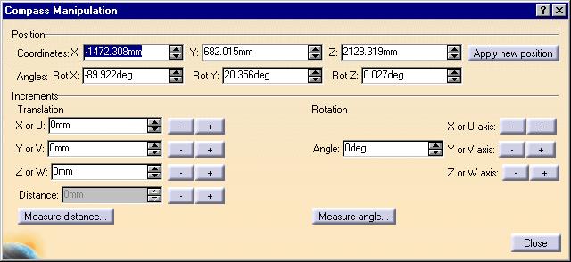
53 3. Click on the Define plane using compass button snap the two resources.. The compass will be placed at the location where you want to 4. Click OK on the Define Reference Plane box. The two resources will snap together. 5. Click on the Select button to exit the Snap command. Click on the resource you want to rotate, then grab one of the handles on the compass with your pointer and move it. Different handles will move/rotate the resource in different directions. You can also double click on the compass to bring up the Compass Manipulation dialog box and enter the required figure in the Angle field. Click on the + or - sign next to the Z axis to rotate it.
54

55 Snap Resources Together This task shows you how to snap two resources together. Resources can be joined at existing connectors, you can create new connectors to join them, or you can snap them together without using connectors. All procedures are described below, beginning with the procedure for snapping resources in which you create connectors. 1. To snap resources together by creating new connectors, click the Snap button. 2. Click one of the resources you want to snap together. The resource changes color and the Define Reference Plane (From) dialog box displays.
.")
56 By default the Define Plane button is selected, allowing you to select a plane for the connector you will create. See Creating Connectors for information about using the Define Plane functions. The two resources will have a Master-Slave relationship to each other - but only if you choose to add a constraint (see below). If you add a constraint the first object you select becomes the slave, and the second object becomes the master. Also note that the first resource you select will move to snap - the second resource you select remains stationary. 3. Select the second resource. The Define Reference Plane (To) box will display - make your selections as explained above. You can also select an existing connector. Click OK when done. The two resources will snap together and the Constraint Options dialog box will display. 4. You can clear the Align, Face and Orientation check boxes and click OK if you want the two resources to remain snapped together without any new connectors being created. To add one or more constraints - which will also result in creating connectors - follow the steps given below. 5. Make your selections in the Snap Options box. Align: You can increase distance between the two resources, but if you change the alignment the


57 slave will snap back to the original alignment. In the image below the distance is increased but the alignment remains the same. Face: The two resources will maintain the face if you move one of them. In the image below the two maintain the same face, though the alignment has changed. Orientation: The two connectors will maintain the same orientation if you move them, i.e. the red arrows visible in the connectors will align. It is therefore important to make sure that the red arrows in the connectors are pointed correctly and oriented correctly with reference to the part. The red arrow is usually set to the "Up" position of the resource, which means that on both resources they should point in the Up direction. If the red arrow points "down" in one resource and "up" in the other, then the resources will snap together incorrectly. You can toggle the position of the red arrow by clicking on the green arrow that is parallel to the plane. Fix in space: If you select this option the position of the master resource is fixed - if it is moved it will snap back to its original position. Attach: Checking this option allows you to attach the two objects. Place manipulator at snapped location: Check this if you want to rotate the snapped object after placing it. The manipulator is placed on the object if you check this. You can then click on the bottom curve of the manipulator (see image below) and rotate the object. It will rotate in increments, based on the value entered in the Snap Angle field. In the image above it is 45 degrees.
58 To remove a constraint select it in the specifications tree and delete it. To remove the 'Fix in space' option right click on the Fix line in the specifications tree, click Properties, go to the Constraints tab, and uncheck the Fix in space box. 6. Click OK when done. 7. To snap resources together using preexisting connectors: a. Click the Snap button. b. Move the pointer over the first resource - the connectors will display. Select the connector. c. Move the pointer over the second resource - the connectors will display. Select the connector and the two resources will snap together. d. The Snap Options box will display. Make your selections and click OK.
59 Quick Snap Resources This task shows you how to Quick Snap two resources together. The Quick Snap procedure allows you to snap two resources together using one of three selection methods. You can select the snapping point on one of the resources using one of these methods. On the other resource the snapping point will either be its origin, or at a connector, as described in Step 2. The three selection methods are: Center of three points (on a circle): the snapping will be the center of three points indicated by you. Center of polygon: the snapping point will be the center of any surface indicated by you. Surface: the snapping point is at any point indicated by you. All three methods are described below. To snap resources together using the center of three points on a circle method, click the Snap Three Points button Click the resource that you want to move. Note: If you click the resource at a connector it will snap to the other resource at that connector. You can create a connector if you want to. If you click the resource at a point other than a connector it will join to the other resource at its origin. If the resource was preselected when you clicked the snap command you will not be able to select a connector. These points apply to all three methods of Quick Snap. In the image below the user wants the paint gun to snap to the robot arm. After he clicks the paint gun the compass displays at the origin of the paint gun to show that the part will snap at that location. You can choose not to display the compass at the snap location by unchecking the option Place compass at snapping point in the Snap Options dialog box. The box displays when you click on any of the Quick Snap buttons. Placing the compass at the snapping location allows you to rotate the resource after it has snapped.


60 3. Define the point on the robot where you want the paint gun to snap, in this case the end of the robot arm, by clicking on three points. You can only select your defining points on the edges of a circle. Note: If you click the three points clockwise the paint gun will attach "inward" as shown in the image below: If you click counter clockwise then the paint gun will attach "outward", which is the correct position in this example.

61 4. To Quick Snap using the center of polygon method, click the Snap Center of Polygon and perform the action detailed in Step 2. button 5. Select the snapping point on the second resource by clicking on a surface. The resource will be placed in the center of the polygon. 6. To Quick Snap using the surface method, click the Snap Surface action detailed in Step 2. button and perform the 7. Select the snapping point on the second resource by clicking on any surface. The resource will be placed at the point you click. If you double click a command you will be in repeat mode. This allows you to snap a resource to a different location, using a different selection method if you want.
. 3.")
62 Placing Multiple Parts in a Run This task shows you how to place a part at several places on a run. 1. Select the part you want to place from the Catalog Browser. 2. Depress the shift key and click on the appropriate place in the run (after the node or segment you are placing it on highlights). 3. The parts will begin to be placed and a dialogue box will display the progress. 4. You can also use the Place a Part Many Times button to place multiple parts. To do so, click on the button, then click on the part in the run you want to place multiple times. Then select the run. The parts will be placed. The following parts can be placed in multiple places using the procedure given above: parts that are stretchable on a run, like a pipe, duct or raceway; turns, like an elbow; and branches, like a tee or a switch.


63 Using Quick Translate to Move Objects This task shows you how to use the Quick Translate command to move elements. This function allows the user to transfer an element relative to a location on another element by any of the following alignment methods: Point-to-Point Point-to-Line Point-to-Plane Plane-to-Plane Plane-to-Point Line-to-Point An object or element when moved using this command does not rotate. 1. With your document open, click on the Quick Translate button. The Translate dialog box opens. Depending upon which From element you select the available To elements will either be greyed out or become active. 2. Select the type of transfer, Point-to-Point, Point-to-Plane, etc. Using the Point-to-Plane method as an example, select a point on the From element in your document and select a plane on the To element.


64 3. The transfer occurs when you click on the To element. Click the Update button, if necessary. In this case, the object or element has moved, aligning the selected point with the selected plane. 4. The function works similarly with the other From/To selection methods and may be applied as the design dictates.
65 Using Path Reservations The following items describe how to use path reservations. Creating a Path Reservation Routing From the End of a Path Reservation, Boundary, or Run Branching a Path Reservation Routing Using the Compass Base Plane Route a Run Within a Pathway Routing from an item reservation

66 Creating a Path Reservation on an Area This task shows you how to create a path reservation on an area. 1. Make the appropriate area active. See Making an Element Active. 2. Select the Path Reservation icon. The Path Reservation dialog box displays. 3. Define the type of path reservation you want to create. 4. Define the routing mode for the path reservation: Point-to-point Orthogonal Slope Directional

67 Edgeline Branch at Center: see Branching a Path Reservation In addition, if you place the compass on an object the Use Compass Origin button will display. If you click the button and start to route the route will start from the compass origin. If you are in the middle of routing, the compass origin will serve as a routing point. 5. To define Section parameters, do the following: a. Click the Section type button. The Section dialog box is displayed. b. Define the section type and the corresponding parameters for each of them: No Section Rectangular
68 Set Point Envelope height Envelope width Display Nominal size Circular Set Point Envelope diameter Nominal size Display Flat Oval. Set Point Envelope height Envelope width Display Radius Corner: Enter or select the: Set Point Envelope Height Envelope Width Radius Corner Display c. The Display buttons allow you to select a display mode of Line/Curve, Solid or Flat. d. Click the Display Centerline button to show the centerline of the run. This will appear as a dashed yellow line. In addition a dashed blue line will appear to display the Set Point setting. This feature works in all display modes, Line/Curve, Solid and Flat. e. Select OK on the Section dialog box.
69 Instead of entering the type of path reservation, the set point and the height, width or diameter in the Section dialog box, you can select an existing path reservation in your document. Once you select the path reservation the Section dialog box will display the same values as the one you selected. To select, click on the Path Reservation button and then click the left mouse button once on the path reservation whose values you want as the default. Make sure the entire path reservation is selected, and not just one segment or node. It will be easier to select the path reservation in the specifications tree. 6. Optional. Key in a value for the turn radius. 7. Click in the drawing to define the routing points. 8. Double-click the last point to stop routing. 9. Click on the Close Loop symbol that shows at the beginning of the run if you want to create a closed loop run. In a closed loop run the ends of the run are joined.
70 Routing From the End of a Path Reservation, Boundary or Run This task explains how to route from the end of a path reservation, boundary, or run. If you route an element with the same type and parameter values as the "source" element (i.e., the element from which the path reservation is routed), you can specify whether the new element you route is a continuation of the source element or a separate element. If you want to use the "Continue" option, be sure that the parent for the source element is active before you begin. 1 Select the Path Reservation icon. 2. The Routing dialog box is displayed. Define the routing parameters. See Creating a Path Reservation on an Area. 3. Place the mouse pointer at the end of the routable from which you want to route. An arrow will display to show the centerline and the support line as you move the pointer up and down the end of the routable. Select the center or support line and begin routing. If you want to route the path reservation, boundary, or run as a continuation of the existing element, you must select the arrow that corresponds to the support line. If the new element you route has the same type and parameter values as the element you selected, these options are added to the Routing Dialog box: Continue Routing Create New Route 4. Select the appropriate Continue option. 5. Click in the drawing to define the routing points. 6. Double-click the last point to stop routing.
71
72 Branching a Path Reservation This task explains how to branch a path reservation from any of these elements: Another path reservation Boundary Contour Run If the "source" element (i.e., the element from which the path reservation branches) is moved or resized, the path reservation is adjusted accordingly. 1. Select the Path Reservation icon The Path Reservation dialog box is displayed. 2. Define the parameters for the path reservation. See Creating a Path Reservation on an Area. 3. Select the element from which you want to route the path reservation. For a contour, select the edge. For path reservations, boundaries, and runs that are displayed with a section, base your selection on the "cues" that are displayed as you move the cursor over the element: A dashed line is displayed when your cursor is over the center of a section. A solid line is displayed when the cursor is over the support line (defined by the set point of the section). 4. If you want to branch from the center of the segment, click the Branch at Center button in the Path Reservation dialog box. The branch will begin from the center of the segment, irrespective of the point in the segment that you route from. If you want to create a path reservation that "branches" from the end of a path reservation, boundary, or run, see Routing From the End of a Path Reservation, Boundary, or Run.

73 Routing Using the Compass Base Plane This task shows you how to use the compass to define the plane on which you are routing. This feature allows you to place the compass base on a plane and route on that plane. 1. Drag the compass and place it on the surface on which you want to route. In the illustration below it is one face of an item reservation and you will place a path reservation on it. 2. Click the Path Reservation button The path reservation is created. and do your routing on the surface. Double-click to end.


74 You can route on any plane on which the compass base can be placed. But you will not be able to route on any surface. You cannot route on the surface of other routables. If you need to route on the surface of a routable then you need to employ free space routing. After you place the compass base on the plane, you can route anywhere in your window and you will be routing on the same plane as the compass base. The illustrations below show one type of free space routing, in which you: Create a boundary and place the compass on a plane. Hide the boundary. Route a path reservation. Show the boundary again with the path reservation on the compass base plane. The last illustration below is a top view showing the path reservation and compass base on the same plane.

75 Route a Run Within a Pathway This task shows you how to route a run within a pathway. 1. With your pathway model open, click on the Route thru a Pathway button. 2. In the Section dialog box that shows select the type of run, the set point and other options. 3. Click on the pathway in which you want to route your run. This displays set points on the pathway. Select a position for the run by clicking on one of the points, e.g. if you select top center the run will align to the top center of the pathway. You can click Apply in the Run dialog box to see how the run looks and to try different positions. Click OK when you are finished.
76


77 Routing from an Item Reservation This task shows you how to route from an item reservation. 1. Click the Run button. 2. Click on the face of the item reservation from which you want to route. 3. Begin routing. The point on the item reservation face from which the run will start depends on the set point of the run. In the illustration above the set point is set at Center Center. If the set point was set at Bottom Center the run would have started at the bottom center edge of the item reservation. To change the set point, click on the Section Type Section dialog box. button in the Run dialog box and select a set point from the drop down list in the
78 Modifying Path Reservations The following items describe how to modify path reservations. Changing a Section Changing the Angle of a Segment Moving Nodes Create a Closed Loop Run Open a Closed Run
79 Changing a Section This task explains how to change parameters that control how the section of an element is displayed. 1. Place your cursor over the element and click the right mouse button. 2. From the pull-down menu, select the element you want to modify and select Definition. The Definition dialog box is displayed. 3. Click the Section button to set the desired section shape to No section, Rectangle, Round, Flat Oval or Radius Corner. 4. If you select Rectangular Section, you can define or change these parameters: Set Point Height Width Display If you select Round Section, you can define or change these parameters: Set Point Diameter Display If you select Flat Oval Section, you can define or change these parameters: Set Point Height Width Display If you select Radius Corner Section, you can define or change these parameters: Set Point Height Width Radius Corner Display
80 5. Click OK on the Section dialog box and OK on the Definition box to complete the change.

81 Changing the Angle of a Segment This task shows you how to change the angle of a path reservation, boundary, or run segment. 1. Place your cursor over the element and click the right mouse button. 2. From the pull-down menu, select the element you want to modify and select the Definition option. The Definition dialog box is displayed. 3. Place the cursor over the support line for that element and click the right mouse button. 4. Select Definition from the pop-menu. The Segment Definition dialog box is displayed. 5. Specify a new value for the Turn Angle. A line is displayed in the drawing to show the new position for the segment. 6. Click OK on the Segment Definition dialog box. 7. Click OK on the Definition dialog box to complete the change. 8. To align a section's normal with the compass Z axis: Bring up the Definition box for the section. Place the compass on a 3D element and adjust the Z axis to the angle you want. Right click on the segment. A pop-up menu will show. Click on Rotate section to compass Z direction. The normal of the section will rotate to align with the Z axis, as shown in the image below.
82

83 Moving Nodes This task shows you how to move the nodes on a path reservation, boundary, or run. In the example below a node will be moved in a pipe run. 1. Place your mouse pointer over the element and click the right mouse button. 2. From the menu that displays, select the element you want to modify, in this case pipe run.1 object, and select the Definition option. This brings up the Definition dialog box, and symbols are displayed on the pipe run to show the location of nodes: asterisks represent non-connected nodes, and Os (circles) represent connected nodes. 3. Do either of the following to move a node: To move a node by keying in coordinates, do the following: a. Right-click the node symbol and select Definition from the pop-up menu. The Node Definition dialog box is displayed. b. Key in new values for X, Y, or Z. c. Click OK in the Node Definition dialog box. To move the node using the cursor, place the cursor over the node symbol and drag it to a new location. See below.


84 A line is displayed to show the new location for the segment. 4. Click OK in the Definition dialog box to complete the change. A node will move parallel to the compass base plane, which is normally XY. To move a node vertical to the base, change the compass base to the XZ plane. 5. To move a node parallel to the compass Z axis. Bring up the Definition box for the routable. Place the compass on a 3-D object where it can be manipulated. Change the Z axis to the direction you want. Click on the square around the node and move it with the mouse button depressed. It will only move parallel to the compass Z axis. If you click on the node itself you will be able to move it in any direction. 6 To move a node of a routable to the origin of the compass. This allows you to move the compass to a specific point on a routable or resource, and then move the node to it. To do this: Bring up the Definition box for the routable which has the node you want to move. Move the compass to the point where you want the node to move. Bring up the Definition box for the node that will be moved. Click the Compass Origin button. The node will move to the compass base, as shown in the image. 7. To delete a node right click on the node and select Delete Node from the pop-up menu that displays.
85


86 Create a Closed Loop Run This task shows you how to modify an existing run in order to create a closed loop run. In a closed loop run the ends of the run are joined. There are two ways of turning an existing run into a closed loop run. Both are explained below Click on the Run button and continue routing from the end of the run. Click the Continue Routing button in the Run dialog box. 3. Click on the other end of the run when finished. The ends of the run will join and form a loop. 4. In the second method, right-click on the run and, in the drop down box that appears, click on the line that describes the run, in this case Run.1 Object. 5. Another drop down box will display. Click on Close Route. 6. The two ends of the run will join. An open end run and closed loop run are shown below.


87 Open a Closed Run This task shows you how to open a closed run. You can only open a closed run at a node. 1. Bring up the Definition dialog box for the run. 2. Click the right mouse button on the node where you want the run to be opened. This will display a drop down box. 3. Click on Open. The run will open at the node.
88
89 Using Lofted Pathways This section ways of creating and modifying lofted pathways. Creating a Lofted Pathway Resizing a Lofted Pathway Moving a Lofted Pathway

90 Creating a Lofted Pathway This task shows you how to create a lofted pathway. When you route a lofted pathway you are actually creating a loft, which is a part. You do not create a run of any sort when you create a lofted pathway. You can route a lofted pathway from an item reservation or a path reservation. 1. Click the Lofted Pathway button. The Lofted Pathway dialog box displays. 2. Select a section type and enter values for height and width, or radius. You can have more than one section type in a lofted pathway.
91 3. Select a section placement. Unlike routing a run or pathway, when you create a lofted pathway you place sections at indicated locations, which are "filled" in by the loft. If you have the Create Path checkbox selected while you are placing sections you will see the loft as you route. It is more customary to leave the box unchecked until all sections have been placed. The following section choices are available (move your pointer over the button to see the type): Free Space: A section will be placed at any location where you click. You can place more than one section at a time by entering the number in the Instances field. Specify the distance between them by entering a value in the Offset field. You can use this option after you have placed at least one section, and in this case you must click the Create button to place the sections. Some basic concepts to consider before placing sections at an angle. When you create the first loft section, you are placing it relative to the global compass. The global compass is visible in your product as the origin. The "global" compass is that which determines the relative XYZ position of your product. When you place loft sections, a "local" compass resides with the last section placed. It is the angle relative to the local compass that determines the position of the next section. The (-) or (+) buttons in the Angular mode follow the "right-hand rule" convention (with your thumb being the axis and the natural direction of the fingers being the positive (+) angle). In the example below (left), two sections have been placed along the global Z axis (positive). The Angular mode has been activated and the Z or W (+) button pressed to create a section at 90deg (about the w/z axis) relative to the previous section placed. In the image below (right), the section was placed activating the Y or V (-) button. The rotation is about the v/y axis.


92 This may well take some getting used to. Experiment with the angular mode in all axes and using a negative value in the Angle field. Angular: This button is grayed out until you have placed at least one section. When you choose this option the section will be placed at an angle relative to the last section placed. The angle and positioning are determined by the values you enter. Enter the angle in the Angle field and click the (-) or (+) button next to the axis about which you want the section to rotate. The section will be previewed. In the Radius field, enter the turn radius relative to the last section. Click Create when you want to place the section. Offset: This function allows you to place the section offset a specified distance from the last section placed. It can be offset along the X, Y and/or Z axis. The distance is specified in the field next to each axis. The section will be previewed. Click Create when you want to place the section. Existing Section: If you want to link your loft to an existing section, click this button and then the section to which you want to link. If you check the Tangency checkbox, the lofted pathway will be perpendicular to a section and the pathway will be more "spline-like". If you uncheck the box the pathway will be more angular. The


93 pathway below was created with the tangency option checked. You can use the compass to manipulate a section after placing it, as shown in the image below. 4. After you have placed the sections, check the Create Path box to create the loft (if you haven't already done so).
94
 button. The Formulas dialog box displays. 3. In the Filter Type field select Renamed Parameters.")
95 Resizing a Lofted Pathway This task shows you how to resize a lofted pathway. You can change the vertical length and horizontal length of a section. 1. In the specifications tree, select the section you want to modify. 2. Click the f(x) button. The Formulas dialog box displays. 3. In the Filter Type field select Renamed Parameters. Select the horizontal or vertical length in the Parameters window, and make your changes in the Edit Name or Value of Current Parameter field. 4. Click OK.


96 Moving a Lofted Pathway This task shows you how to move a lofted pathway. You can move an extremity, a section or the entire pathway. 1. To move an extremity. click and drag the section horizontally or vertically, then click the Update button. 2. To move the entire section, click on the section so that it is enclosed in green "framework", then click and drag, Click the Update button to end. 3. To move the entire lofted pathway, select all its sections and lofts, so that all of it is enclosed in a green framework, and click and drag. It is easier to move a pathway if you have created it under a Reservations Network, in which case you can select all parts of the pathway by selecting the network.
97
98 Managing Systems Ways of creating and managing systems are explained here. Creating a Network Creating a Logical Set Saving a Network as a Separate Document
, create a logical set under it, and then create pathways under them.")

99 Creating a Network This task shows you how to create a network. A network is a mechanism for organizing and grouping logical sets and routables. You can create a network (such as a Walkway Net), create a logical set under it, and then create pathways under them. A network will display in the specifications tree only as an organizational element. The pathway will also display in your viewer. 1. Click on the Reservations Network button. displayed. The Reservations Network Creation dialog box is 2. Click on the down arrow and make a selection in the pull-down menu to designate your network as being of a certain type, i.e. walkway. 3. Click OK.
 and then create runs under them. See Creating a Network for more information. 1. Click on the Logical Set button.")
100 Creating a Logical Set This task shows you how to create a logical set. A logical set is a mechanism for organizing and grouping. You can create logical sets under a network (such as a Walkway Net) and then create runs under them. See Creating a Network for more information. 1. Click on the Logical Set button. The Logical Set Creation dialog box is displayed. 2. Click on the down arrow and make a selection in the pull-down menu if you want to designate your network as being of a certain type, i.e. work set. 3. Click OK.


101 Saving a Network as a Separate Document This task shows you how to save a network as a separate document.. This function is needed if you want to work separately on a component of a larger project. If you save the network as a separate document you can open it without having to open the entire project. At the same time it remains part of the larger project. 1. When creating a new Reservations Network check the Create new document option. 2. Enter a file name in the box that displays and click OK. The new document appears in the specifications tree as a child of whichever element you created it under. In the specifications tree, the icon next to a network created as a separate document is different from that which is not created in a separate document. In the illustration below Electrical Assembly is created as a separate document, Reservations Network1 is not. 3. When you save the project a dialog box will ask if you want to proceed with other document save operations. Click OK.
102
103 Modifying Routables The following procedures describe how to modify routables. Using the Definition Dialog Box Positioning a Branch Connecting a Run Disconnecting a Run Break run at a branch Convert Star Connection to Master-Slave Type Create an offset connection between segments Position Segment Relative to Plane or Another Segment Display Information About Routables

104 Using the Definition Dialog Box This task gives you an overview of the definition dialog box. You can make modifications to a routable using the functions contained in this box. Specific task-oriented modifications are explained elsewhere in this section. You should be familiar with the concepts explained in Routing a Run to be able to take full advantage of these functions. Note that some applications, like Systems Routing, do not utilize design rules and the norule conditions apply to them. 1. Right click on a routable and, in the drop down menus that display, select the routable (in this case Run-0049 object) and then Definition. 2. This brings up the Definition dialog box. 3. The Name field allows you to change the routable's instance name. 4. The Section button lets you change section parameters, as explained in Routing a Run. 5. Click one of the Turn Type buttons if you want to change the turn type. No Turn: The turn radius for all turns is changed to 0. The Turn Radius field is not displayed. Uniform Turn: All turns in the run have the same turn radius. Mixed Turn: Turns in the run can have different turn radius. 6. The Press to Use Rule button indicates if you are using the design rules. In the image above it is on, which is why the Turn Radius and Minimum Length fields are grayed out. You can click the button to go to a no-rule state, in which case the Turn Radius and Minimum Length fields will no longer be grayed out. See Routing a Run for more information.

105 7. The Display Error Report button is green when there is no error in the run. It turns red when you insert a value or make some other change to cause an error. Click the button to display a report. This error function checks to make sure that the turn radius and minimum length conform to the design rule. 8. The Turn Radius field displays the turn radius. To change it you need to display the Node Definition dialog box (see Moving Nodes) and enter a value. If you introduce an invalid turn radius, by entering a value in the Node Definition dialog box, then the Display Error Report button will turn red. (You can also introduce a turn radius error by shortening the length of one or both segments.) A red arc will also display on your run. The ends of the arc are the minimum point to which each segment should be routed for a valid turn. In the example below, the segment is not long enough to support the turn radius value entered by the user. 9. The Node Edit Table button displays a table containing node values - see Moving Nodes. 10. The Minimum Length field displays the minimum length of each segment. You cannot change the value in this field if you are using design rules. 11. The Total Length field displays the total length of the run. You cannot change the value in this field.

106 Positioning a Branch This task shows you how to position a branch routable precisely..... This function allows you to use the Offset Plane feature to position the Branch at a precise point along the support or center line of the Main routable. In the illustration below the branch path reservation will be placed in the center. A branch is also referred to as a Slave Connector, and the routable of which it is a branch termed a Master Connector. The two routables must be connected for the function to work. 1. Select the Main routable and click the Offset Plane button. The Main will display nodes at the beginnings and ends of segments and a square (section detail) in the center of segments. 2. Move the mouse pointer to the Main Routable - a white square shows. Snap the white offset plane square to any of the nodes or section detail squares and click the left mouse button. A blue square will appear. See Using Offset Planes for more information. 3. Click the right mouse button on the Branch. In the menu that displays, select the line that corresponds to the Branch element, in this case path reservation2 object, then click Definition in the pop-up menu. This displays the Definition dialog box.

107 4. Click and drag the support line toward the blue square. A label will display the distance. Release the button when it reads 0 ft and click OK on the Definition dialog box. The Branch path reservation will assume the new position. To place a routable at a precise distance from an end or a node, snap the offset plane to that node or end. Then enter the distance in the step input box. Follow the steps above to move the Branch and click OK on the Definition dialog box when the required distance is reached.

108 Connecting a Routable This task shows you how to connect a routable. You can use this function to connect two routables, connect a routable to a part or connect to a hole connector. A run, rather than a path reservation or boundary, is used here to illustrate the function. 1. Click the Connect Run button and then select one of the elements you want to connect. The element you select first will be the slave element and will be the one that moves to join the master element. You must click on one of the green connection indicators on the slave run, as shown in the illustration below. 2. Select the master element. The first run will move to connect to the master run and the connection symbol will display.


109 The slave run will connect to the master at the green connection indicator that you select. You can select any point on the master run for the slave to connect to. If you select a point in the middle of the master run then you may have to move the two near to each other to create the connection. The images below show connections in the middle and at the end. You can also connect a run to a part using the method described above. If the part does not have a connector then you must create one. 3. You do not need to select the green connector indicator to connect a run to a hole connector. You can click on a segment of the run instead. In the image below the user first selected the run segment and then the hole connector on the clamp to place the run through it.
110
111 Disconnecting a Routable This task shows you how to disconnect a routable that is connected to another routable or to a connector. A run, rather than a path reservation or boundary, is used here to illustrate the function. 1. Click the Disconnect button you want to disconnect. and then click the connection symbol between the two elements 2. The elements will be disconnected and the connection symbol will disappear.


112 Break a Run at a Branch This task shows you how to break a run at a branch. There may be times when you want to move all the segments of a connection at the same time. Breaking runs at branch intersections is one way. When you break runs at branch intersections you create what is called a star connection. In this type of connection (recognizable by a square or diamond-shaped symbol), all the segments joined at a connection will move if you move the connection. In a master-slave connection, the slave will maintain a connection with the master if you move the master. The illustrations below show 1) a run with a star connection; 2) the star connection is moved by dragging with the mouse; and 3) all nodes connected to the star connection move to the new star connection location in order to maintain that connection.


113 1. Click on the Star Connection button. 2. Click on the routable, system or network you want to convert to star connection. A branch connection symbol will display at all branch connections in the selected element. A pop-up panel will ask: OK to continue? Click Yes. The connection will be converted. The illustrations below show a branch connection converted to a star connection, with the diamond-shaped star connection showing.
114 The illustration on the left shows that the main section consists of one segment. But after conversion to a star connection it is broken at the connection into two segments.

115 Convert Star Connection to Master-Slave Type This task shows you how to convert a star connection to a master-slave type of connection. 1. Display the Definition dialog box for the run. To do this click Edit in the menu bar and then on the line that corresponds to the run, e.g. "Path Reservation.1 object." This displays the Definition dialog box. (You can also enter Cntrl-Enter, or click the right mouse button on the run, to display the dialog box.)

116 2. Place the mouse pointer on the diamond-shaped star connection and click the right button. This will bring up a pop-up panel. Click on Convert to master/slave connection.


117 Create an Offset Connection Between Segments This task shows you how to create an offset connection between two segments. Creating this connection makes a master-slave relationship between the two and maintains a fixed distance between them. If you create the connection only between two segments, the two will maintain the offset if you move one. But other segments of the slave routable may change in length to allow the offset to be maintained between the two segments that have a connection. If you do not want this to happen you can create a connection between the other segments too. 1. Click the Create an offset segment connection button. The Run dialog box displays. 2. Select the segment you want to be the slave. The first segment you select becomes the slave, while the second becomes the master. 3. Select the second segment. The compass displays and you can see a connector line between the two.. 4. Enter the offset distance and select your options in the Run box. You can choose to have the offset connection between the: Outside edge to outside edge Centerline to centerline Outside edge to centerline

118 5. To create a connection between other segments of the same two routables select other segments in the same sequence given above. 6. Click OK. The connections will be created. 7. To modify the connection, select the slave run, click the Create offset segment connection button, select the slave segment and enter your changes. 8. To delete offset connections select the slave routable, right click, then click on the line corresponding to the routable and click Delete offset connections. All connections between the two routables will be deleted.

119 Position a Segment Relative to a Plane or Another Segment This task shows you how to position a routable segment so that it is a defined distance away from a reference plane or from another segment. The function can be used to make a segment clear an existing structure or in situations where it is necessary to position it a certain distance from another object or segment. 1. In the example below the routable, in this case a run, is colliding with the beam. The object is to move the segment up so that it passes just over the beam. 2. Place the offset plane on top of the beam and bring up the Definition dialog box for the routable. 3. Right-click on the segment you want to move. A drop down menu will display. Select Offset segment.


120 4. Select Offset segment. The Offset segment dialog box will appear. 5. Select Make segment parallel to reference plane and then select either the, Outside edge to reference plane button or the Center line to reference plane button. See Step 9 to offset to another segment. 6. Enter a distance in the Offset field. If you enter 0 the routable will be placed on top of the beam if you have selected Outside edge to reference plane. If you select Center line to reference plane then entering 0 in the Offset field will place the center line of the routable on top of the beam.
121 7. Click the Offset to far side or Offset to near side button. These buttons will place the routable on opposite sides of the reference plane. 8. Click Preview if you want to, then click OK and then OK again in the Definition dialog box. The run segment will be placed on top of the beam. 9. To position a segment a certain distance from another segment, select the Offset to another segment option and click the segment to which you want to offset. Click one of the three buttons: Outside edge to outside edge, Center line to center line or Center line to outside edge.
122 Display Information About Routables This task shows you how to display information about routables. It works only when you are performing an action with a routable, such as placing a part, branching a run or creating an offset route. To display more detailed information see Generating Detail Information. 1. Go to Tools - Options, Equipment & Systems. Select the Display tab and check the Analysis Mode box. 2. Place the pointer over the run. If a segment is highlighted you will see the length displayed. If a node is highlighted you will see the angle between two adjacent segments, the coordinates of the node and the bend radius if there is one. 3. Click the button again if you do not want to see the information.
123 Using Layout Tools The following procedures describe the tools available in System Space Reservation for advanced layout functions. Mirroring Elements Rearranging Elements Moving Multiple Elements Changing the Properties of Multiple Elements Performing an Inclusion Analysis Distributing Elements Using Offset Planes and Advanced Offset Planes
 you want to move. (You can also select after Step 2.) 1. 2. Click the Mirror icon. 3.")
124 Mirroring Elements This task shows you how to move one or more elements to the opposite side of a selected plane, as a mirror image. It also shows how to copy one or more elements to the opposite side. Select the element(s) you want to move. (You can also select after Step 2.) Click the Mirror icon. 3. The Reference panel will display if you already have a reference plane defined (by having used the offset plane command). Click the New Reference Plane button and follow Step 4 to define a new reference plane. Follow Step 4.b if you want to use the existing reference plane. The Reference panel will not display if you do not have a reference plane already defined. 4. Define a reference plane across which to mirror the element by doing the following: a. Place your cursor over a geometric element that defines the plane (e.g., a construction plane, boundary, area contour, item reservation). As you move the cursor, a small white rectangle is displayed to show the selectable planes, as shown below. If you do not see the white rectangle, zoom out from the drawing. The white rectangle cannot be displayed if the element under your cursor is displayed too small.
125 b. Click to select the plane. The selected elements are mirrored to the other side of the plane, as shown below.

126 5. To Mirror and Copy the elements, follow the steps outlined above and then click the Mirror and Copy icon. The selected elements will be copied to the other side of the plane. In the illustration above, the selected elements will stay where they are and two similar elements will be added to the other side of the plane.
127 Rearranging Elements in the Specification Tree This task shows you how to transfer elements in your layout from one level of the specification tree to another. Make the appropriate element active. 1. You must make active an element that is at least one level higher than both the source element (i.e., the one that is being transferred) and the target element. For example, in order to transfer ArrBox5, ArrBox6, ArrBox7, ArrBox 8, and ArrBox9 to ArrArea3, shown below, ArrArea1 or Product1 must be active. 2. Select the elements you want to transfer.
128 3. Select the Transfer Elements in Tree icon. 4. Select the element to which you want the elements transferred. The target element must also be a child of the active element.
 the element you select in Step")
129 The elements you select in Step 2 become children of (i.e., subordinate to) the element you select in Step 4.
130

131 Moving Multiple Elements This task shows you how to move several elements at the same time. You can move catalog resources as well as the following elements: item reservation, area, space reservation, run reservation, path reservation and boundary reservation. 1. Select the resources or elements you want to move. You can do this by placing the mouse pointer on each one and clicking the left button while holding down the Ctrl key. Another way is to hold down the left mouse button and drag the mouse pointer. Place the rectangle that shows around the elements you want to select. There are other selection methods also. 2. Drag any of the elements or resources and all selected elements and resources will move. You can drag an element or resource by placing the mouse pointer on the dot that shows in the center of selected elements or resources, holding down the left mouse button and moving the pointer to where you want to place the selected elements.

132 Changing the Properties of Multiple Elements This task shows you how to change the properties of several elements at the same time. The elements whose properties can be changed are: item reservation, space reservation, area, run reservation, path reservation and boundary reservation. 1. Select the elements whose properties you want to change. You can do this by placing the mouse pointer on each one and clicking the left button while holding down the Ctrl key. Another way is to hold down the left mouse button and drag the mouse pointer. Place the rectangle that shows around the elements you want to select. There are other selection methods also. See Infrastructure. 2. Click Edit-Properties to bring up the Properties dialog box.

133 3. Make your changes and click OK or Apply. You can also make changes to one of the elements instead of all. Click on the down arrow next to the Current Selection box. This will display a drop down list of all the elements you selected. Select the one you want to make changes to. You may need this if, for instance, you have two areas but want to change the properties of one area only.
. 1. Right-click the area on the specification tree. 2. From the pull-down menu, select the area object and select the Verify Inclusion option.")
134 Performing an Inclusion Analysis This task shows you how to find out if elements that are logically contained in an area (in the specification tree) are also physically located within the contour of the area (in the drawing). 1. Right-click the area on the specification tree. 2. From the pull-down menu, select the area object and select the Verify Inclusion option.


135 The Verify Inclusion dialog box is displayed. 3. Define the parameters for the analysis: Type Inclusion reports which elements are partially inside or touching the selected area. Inclusion No Contact reports which elements are completely outside of the selected area. Scope: 1 Level checks the inclusion status of elements one level down from the area in the specification tree. All levels checks the inclusion status of all elements below the area in the specification tree. 4. Select OK. The Results Window is displayed. You can select entries in the report to highlight the corresponding element in the drawing.
.")
136 Distributing Elements This task shows you how to distribute elements within parameters that you define. 1. Select the elements you want to move. 2. Select the Distribute icon. 3. Define a reference plane for the distribution by doing the following: a. Place your cursor over a geometric element that defines the plane (e.g., a construction plane, boundary, area contour, item reservation). As you move the cursor, a small white rectangle is displayed to show the selectable planes, as shown below. A line perpendicular to the rectangle shows the direction in which the distribution would be performed. If you do not see the white rectangle, zoom out from the drawing. The white rectangle cannot be displayed if the element under your cursor is displayed too small.

137 b. Click to select the plane. The selected elements are distributed along the line perpendicular to the plane, as shown below.
138 Using Offset Planes and Advanced Offset Planes This task shows you how to define a plane to use as a temporary reference for positioning other elements. The second part of the document explains the use of an advanced offset plane, which allows you to define origin, orientation and other parameters. 1. Select the Offset Plane icon. 2. Define the reference plane by doing the following: a. Place your cursor over a geometric element that defines the plane (e.g., a construction plane, boundary, area contour, item reservation). As you move the cursor, a small white rectangle is displayed to show the selectable planes, as shown below. If you do not see the white rectangle, zoom out from the drawing. The white rectangle cannot be displayed if the element under your cursor is displayed too small. b. Click to select the plane. The white rectangle changes to a blue rectangle, and remains displayed on the reference element, as shown below.

139 The reference plane can now be used as a reference to position other elements. 3. Use the advanced offset plane feature to set your plane reference, origin and orientation settings as follows: a. Click the Advanced Offset Plane button. The Define Plane dialog box will display. b. The Define Plane button is selected by default. However, you can select any button in the Define Plane box. Click when you have found a location. The plane manipulator displays. Click on the buttons in the Define Plane dialog box to make your selections. See Creating Connectors on using the buttons. c. Click OK when done. The reference plane will be created.
140 Tasks for Space Reservations The following tasks describe advanced space reservation routing. Routing Path Reservations With a Slope Routing Path Reservations in Any Direction Route a run at an offset of a routable Route a Run Along a Spline Fixing Broken Routables Edgeline: Routing Parallel to a Run
141 Routing Path Reservations With a Slope This task shows you how to route a path reservation with a slope. 1. Click the Path Reservation icon The Routing dialog box is displayed. Click the Slope icon. Key in a value for the slope and press Enter. 4. Click in the drawing to define routing points, changing the slope as needed. 5. Double-click the last point to stop routing.
142 Routing Path Reservations in Any Direction This task shows you how to route a path reservation in any direction. 1. Click the Path Reservation icon. 2. The Routing dialog box is displayed, and crosshairs track the movement of your cursor in the drawing. Click the Directional icon. The compass is displayed in the drawing. 3. Define the first point to begin routing. If the first point is a free point, the default direction for routing is along the X axis. If the first point is the end point of a line, the default direction is along that line. 4. Do either of the following to change the direction for routing: Press the Shift key repeatedly until the desired axis is highlighted. Select and drag an axis to rotate it. The angle at which the axis is turning is displayed. 5. Click in the drawing to define additional routing points, changing the direction for routing as needed. 6. Double-click the last point to stop routing.

143 Route a Run at an Offset of a Routable This task shows you how to route a run at an offset of a routable. This function allows you to create a run paralleling an existing run, a defined distance apart. 1. Click the Create an Offset Route button. The Run dialog box displays. 2. Select a segment of the run to which you want an offset. The compass is placed on the segment. 3. The direction in which the Z axis of the compass is pointed determines where the new run will be placed: you can place the new run or runs to the inside, to the outside or stacked on top of the existing run by adjusting the compass. 4. Enter your options in the Run dialog box. Click either the Constant Radius or Constant Clearance button. If you click the Constant Radius button the radius of the turns will be maintained but the offset may vary. If you click the Constant Clearance button the offset will be maintained but the radius of the turns may change. Select one of the Offset Between buttons to indicate whether you want the offset measured from outside edge to outside edge, center line to center line or center line to outside edge. A negative offset may be entered to offset in the opposite direction to the compass Z direction.

144 5. Click OK. The offset run(s) will be created. In the illustration below the run has been created with the Constant Clearance option.

145 Routing Along a Spline This task shows you how to route a pathway or functional path reservation along a spline. 1. Import the model which contains the spline into the Systems Routing workbench. 2. Click on the Route from Spline button. 3. Select type of path and enter other options. Note: The SAG option is used to define the maximum distance a segment can be from the spline. The pathway that is created consists of straight segments, as you can see in the illustration below. The smaller the SAG number entered, the closer the path will resemble the spline. But this will also cause more segments to be created. 4. Select Create connection to curve if you want a connection between the pathway and the spline. If this option is checked the pathway will move if the spline is moved. 5. Click on the spline. The route is created.

146 Fixing Broken Routables This task shows you how to fix - or rejoin - routables in which segments have become separated. In the illustration below the dotted line - the broken routable indicator - shows that a run has become separated at that point. You can re-join the run in one of several ways, depending on the nature of the break and your requirements. The methods are as follows: 1. Bring up the Definition dialog box for the run, then place the mouse pointer over the broken routable indicator and click the right mouse button. This will display a pop-up menu. Click Create Segment. 2. Bring up the Definition dialog box, then drag one of the segment handles to re-join the run.

147 3. Bring up the Definition dialog box. An arrow will display at each end of the broken routable indicator. Drag one of the arrows (depending on circumstances) to re-join the run. In the illustration below, one segment of the run has been moved to connect to the portion of the run still connected to the pump. 4. In certain cases you will see the Auto Route option beneath the Create Segment option in the pop-up menu (See Step 1). This happens when a segment connecting two parallel routables (which are on different X-Y planes) is broken. Select Auto Route. The Auto Route dialog box will display. Click on the Toggle button. Options for re-joining the run will be shown as a dotted line. Click OK to make your selection.
148

149 Edgeline: Routing Parallel to a Routable This task shows you how to route parallel to, or at an offset of, a routable. See also Route at an Offset of a Routable and Position Segment Relative to Plane. This function is used when you have an existing routable and want to route parallel to it, or at a certain clearance from it. It is sometimes known as edgeline routing. You can also place an offset plane on a surface and use it as a reference point. 1. Display the path reservation you want to route parallel to and click the Path Reservation button 2.. The Path Reservation dialog box displays. Click the Edgeline button. The Distance field will display and the Offset and Clearance buttons will appear on the Path Reservation dialog box. If you click the Offset button the distance between the two path reservations will be measured from centerline to centerline. If you click the Clearance button the distance between the two nearest edges will be measured. If there is a part, the distance will be measured from the part. If there is no part the distance will be measured from the path reservation. 3. Enter the distance between the two path reservations. If you enter 0 and click the clearance button, the two path reservations will touch at the edges. 4. Click at the starting point. The compass will display at that point. 5. Move the compass so that the Z axis points in the direction that you want to route, which should be in the direction of the path reservation that you want to parallel. You can do this by moving it manually, or by clicking the second mouse button once and then toggling the shift key.


150 6. Once the direction is selected, route toward the path reservation you want to parallel. When the centerline of the target run is highlighted you can press the Shift key to toggle between various "solutions," or various sides. In the images below there are only two solutions and you can route on two sides of the target run. The images below show routing using a run, the procedure is the same with path reservations. 7. Select the target routable after you have decided which side you are routing on. 8. Begin routing and double click to end. The finished routable is shown below. You can place an offset plane on a surface and use it as a reference to route parallel to, or to keep a certain clearance from. After placing the offset plane use the procedure described above.
151 Creating and Modifying Connectors This section explains ways of creating and modifying connectors. Create Connectors Use the Compass to Manipulate Connectors Modifying or Deleting Connectors Creating Duplicate Connectors Using the Plane Manipulator Place Connectors on Hole in V4 Document

152 Create Connectors This task shows you how to create a connector. Connectors can only be created on objects that have existing geometry that satisfies the rules of connector creation. If existing geometry is not present, you will have to create the geometry. 1. If the resource is not active, make it active by double-clicking in the specifications tree. 2. Click the Build Connector button. This will bring up the Manage Connectors dialog box. The Manage Connectors dialog box will list all connectors on the selected part. To see a connector and its associated geometry on the part, select a connector from the list. Adding a connector is explained below; Delete, Modify and Duplicate are explained elsewhere in this section. To Publish a connector means you are allowing people who do not have write access to your document to establish a connection. This is explained further in Using Work Packages. You can Publish or Unpublish connectors using the two buttons. 3. Click the Add button. The Add Connectors box displays.
 part connector has flow direction built in and you must select a flow direction also from the drop down menu. The mechanical part connector has no flow direction.")
153 Select the type of connector - piping, HVAC, etc. In some applications the flow direction field will be available. The piping (or tubing) part connector has flow direction built in and you must select a flow direction also from the drop down menu. The mechanical part connector has no flow direction. Another type of connector - the nozzle connector - will be available if you are placing a connector on a nozzle. A nozzle connector must be placed on the end of the nozzle that connects to equipment. A part connector is placed on the end that connects to the pipe or duct. An electrical part connector should only be placed on a socket. The electrical part connector should be placed on the end of the socket that connects to equipment. A cableway part connector should be placed on the free end of the socket that does not connect to equipment. When you are placing a connector on a Bendable, such as a bendable pipe, you must use the Define New Geometry option. You must not use existing geometry to place the connector. You can name each connector by selecting in the Name field. This is useful for some functions, such as designing using a schematic. The concept of Publishing or Unpublishing a connector is explained above. Check the checkbox as necessary.
154 Face, orientation and alignment are explained below. The orientation, alignment and face must be defined correctly before a connector can be created. To explain what these are, the face is the surface to which you attach a connector. As an example, if you want to attach a clock to your office wall, the wall is the face. You want the numeral "12" to be up, so you orient the clock accordingly. This is the orientation. The alignment is the direction in which the clock face is pointed - normally it would be perpendicular to the wall. When creating a connector, the alignment always has to be perpendicular to the face. The face is generally defined using a face of the part, such as the end of a pipe. Alignment is usually defined using a line, such as the not-shown line along the centerline of a pipe. Orientation is defined using the xy plane, or another plane or face to define an "up" direction. In the illustration below the Z axis indicates the alignment of the connector. It also indicates the direction in which routing will occur. The X and Y axis together define the orientation. They are useful when attaching two resources. It is necessary to select geometry in the part to which you want to attach a connector so that these three characteristics are correctly defined. If the part does not have the necessary geometry then you must create it. 4. If you want to create a connector using the part's existing geometry click the Use existing geometry option. Click the Select Face button to select a face. Selectable faces will highlight as you move your pointer over the part. Click this button to select the alignment. You will only be able to indicate the alignment by selecting a line - from the construction geometry, or elsewhere in the part if there is one. You can only select a line that is perpendicular to the face plane. Click this button to select the orientation. You will only be able to select a plane that is
155 perpendicular to the face you selected. Some connector types require you to place a datum point. The datum point is placed by clicking this button and then clicking a 3-D point on the part. The datum point is used as follows: Lofted reservation section: Datum is used to define where the spline will start and end when creating lofted reservations. Tubing & waveguide parts: Datum is used to define where the spline will start and end when creating flexible tubes. Hangers: See Hanger Design documentation. You can display the part construction geometry, if there is any, to make it easier to select existing geometry. Do this by: Right click on the part entry in the specifications tree. Click Hide/Show. The part will disappear from the screen. Click the Swap Visible Space button. The part will reappear on your screen with the construction geometry visible. Clicking the button again will toggle you back. 5. The fields under Classify Connector will become available after you have successfully selected the geometry explained in Step 4. Click on the down arrows to make your selection. Select a type. For Flow direction, select In, Out, InOut or None. Select the Face type. A Hole connection allows a routable to pass through it - it is useful for placing parts like clamps along a run without cutting a tube. A Face connection will stop a routable and not allow it to pass through. Select an alignment. Choose an orientation: Circular will allow the connector to attach to another connector at any orientation; round ducts and pipes, for instance, do not need a well-defined "up" direction because they can rotate. A Rectangular orientation is used for parts like rectangular ducts; they do not have a strict ''up" direction. Up allows the connector to attach to another connector or part in the up position: horizontal trays, for instance, require a well-defined "up" position. You can also use the "up" orientation for a hole connector. In the image below, the connector on the right has the up orientation, the connector on the left does not.

156 The number in the Number field is assigned by the application. This can be significant because when you are creating a new connector, you have the option of using the alignment and orientation used in the previous connector after you select the face. You can choose to do this, or select a new alignment and/or orientation. 6. Click OK. The new connector will be listed in the Manage Connectors box. 7. To define new geometry for placing a connector, select the option Define new geometry, then click on the Select plane button. The Define Plane box will display. 8. Use the functions provided by the Define Plane box to reposition the connector, if necessary, as explained below. (The colors of the buttons may be slightly different in some applications.) Click the Define Plane button to redefine the plane as well as the origin by clicking once on the face. Click the Define Plane using Compass button to redefine the plane using the compass. Click the Define 3-point Plane button to define the plane by clicking on any three points with your pointer. The connector will be placed on the first point you click. Click the Define Line-Point Plane button to select the plane by clicking on a point and a line, like an edge. The connector will be placed on the first point you click. Click the Define Line-Line button to select the plane by clicking on two lines. The plane will be defined by the first line selected. But if the two lines are parallel the plane will be defined as the plane in which both lines exist.

157 Click the Define plane at center of circle button to select the plane by clicking three points on the edge of a circle. This method is used for multi-cad documents, usually for CGR circles. You can click at points where two lines meet or in the center of a face. The Z axis of the plane manipulator will be placed according to the right hand rule. If you click clockwise the Z axis will point into the object. If you click counter clockwise the Z axis will point out from the object. Click the Define plane at product origin button and then the object to place the plane manipulator on the origin of the object. The plane manipulator axis will match that of the product. Click the Define Orientation button to change the orientation. Click the button and then click a point or a line. If you click a point the X axis will point to it. If you click a line the X axis will become parallel to the line. Use the Move Origin buttons to define the plane. Define Origin at Plane or Compass allows you to define the origin using the compass or plane command. You use the compass or plane as the base plane along which the origin can be selected. Define Origin at Point or Center of Face lets you select the origin by clicking on a point or face. Define Origin at Center of Circle allows to select the origin by clicking at three points - the origin will be placed in the center of an imaginary circle drawn using those three points. The plane and orientation will not change when using this command. 9. Click OK. The connector will be placed and the Add Connector dialog box will display again.< 10. Make your selections in the fields under Classify Connector as described in Step 5. Click OK.

158 Using the Compass to Manipulate Connectors This task shows you how to use the compass to manipulate connectors placed on resolved parts. You can use the compass to manipulate connectors placed on resolved parts only. Use this method when adding a new connector, or by using the Modify command. Both are explained below. 1. To manipulate while adding a connector, drag the compass and place it over the connector while the Define Plane box is displayed. 2. To manipulate using the Modify command, select the resource, click the Manage Connectors button and, in the Manage Connectors dialog box, select the connector in the connectors list. Click the Modify button. 3. The Modify Connectors box will display. You can now drag the compass and place it over the connector. 4. Click on one of the handles on the compass and manipulate the connector to the desired position. You can change alignment, orientation and origin using the compass. 5. Click OK on the Modify Connector or the Define Plane dialog box when done. Remove the compass from the connector by dragging it to the axis.

159 Modifying or Deleting Connectors This task shows you how to modify or delete connectors. You will not be able to modify or delete a connector that has constraints or connections. 1. To delete a connector select the resource by double clicking in the specifications tree and click the Build Connectors button. This will display the Manage Connectors dialog box. 2. Select the connector in the connectors list and click the Delete button. The connector will be deleted. 3. To modify a connector click the Modify button in the Manage Connectors box. The Modify Connectors dialog box displays. 4. Follow the procedures described in Step 4 and subsequent of Creating Connectors.


160 Creating Duplicate Connectors This task shows you how to create one or more duplicate connectors. You can only make duplicate connectors on a resolved part. Connectors can only be duplicated on the same part. With your resolved part displayed, click the Build Connectors button. This will open the Manage 1. Connectors dialog box. 2. Select the part. This will display all connectors on it and also display a list in the dialog box. 3. Select the connector you want to duplicate and click Duplicate in the Manage Connectors dialog box. The Duplicate Connectors dialog box displays. 4. Enter the spacing between the connectors and the number of connectors you want.


161 5. Drag the compass and place it on a surface with the Z axis pointing toward the direction in which you want the new connectors located. The two illustrations below show how you can change the location of the new connectors by changing the direction of the Z axis. 6. Click OK.

162 Using the Plane Manipulator This task shows you how to use the plane manipulator. You can use the plane manipulator to change the orientation, alignment, plane and location of the plane you propose to create. The X and Y axis indicate the orientation and the Z axis indicates the alignment. For example, if you create a connector and route from it, routing will occur in the direction indicated by the Z axis. 1. To change the orientation of an axis, click on the dot at the end of it. It will flip 180 degrees. 2. To move the manipulator along any axis, click and drag on that axis. The manipulator will move and the distance will display. 3. Click on the origin (red square) and drag to move the manipulator to a new plane. 4. To change the orientation you can also click and drag any of the arcs in the manipulator to rotate it. It will rotate in increments, which is 15 degrees in the image below. To change the degree of rotation click Tools-Options, select Equipments & Systems and select the General tab. Enter the degree of rotation in the Snap Angle field. For instance, if you enter 45, the manipulator will snap in increments of 45 degrees, counting its starting position as 0. It will snap to the nearest 45 degree step - if you move it to 88 degrees from its starting position it will snap to 90 degrees.
163

164 Place Connector on Hole in V4 Document This task shows you how to place a connector on a hole in a V4 document that has been imported into V5. 1. Click on Start - Mechanical Design - Part Design. You need to have a license to use the Part Design product. If you do not have a license, use the compass method outlined below to place the connector. 2. Select the part geometry near the hole on which you want to place a connector Click the Sketcher button. The sketching mode will appear. Zoom into the hole and, using the three-point circle tool, draw a circle that conforms to the inside of the hole. Create a point at the center of the hole, using the point tool. This is all the geometry you need in order to place a connector over the hole. You can now follow the steps outlined in Creating Connectors.

165 6. Using the compass Position the compass on the center line of the hole (holes in V4 models have a center line). 7. Change to a view that gives the clearest view, in this case the top view. 8. Adjust the compass so that you have the correct plane and alignment. The compass provides the geometry needed by a connector to snap to. 9. Follow the steps given in Creating Connectors.
166 Creating and Using Resources This section explains ways of creating and using resources. Changing the Reference File for a Part Change the Parameters of a Part
167 Changing the Reference File for a Part This task shows you how to change the reference file for a part. When a part is placed in a document, it has a reference file associated with it. This reference file contains data about the part. To save disk space, the application normally uses one reference file for all similar parts - an elbow that has been placed nine times in a document will have one reference file for it. This also means that you cannot change the dimensions of one or more of those elbows. This function allows you to create a unique reference file for one or more parts, allowing you to assign unique parameters to them. Using this function you can: Assign a unique reference file to a part. 1. Assign a part the unique reference file (and parameters) of another part. With your document open, click the Change Part Reference button dialog box will display.. The Change Reference

168 2. If you have already selected a part, the file name will display in the file name field; if not it will display when you select a part. If you want to change the file name make sure you have not already assigned it. 3. Click OK. 4. To assign an existing unique reference file to a part: If one of the parts in your document already has a unique reference file you can assign it to other parts. Select the part or parts to which you want to assign a reference file; click the Select New Reference button in the Change Reference box; then select the part that has the unique reference file. You will see the file name change to the unique reference file name in the specifications tree.


169 Change the Parameters of a Part This task shows you how to change the parameters of a part. 1. Select the part, in this case an elbow at the end of a run, and click the Edit Part Parameters button display the Parameter Explorer dialog box.. This will
170 2. The box will display a list of parameters that can be edited for the part you selected. Select one of the parameters. 3. If it is possible to change this parameter by entering a value in the Parameter Value field then do so. If the Value field is grayed out then click the button to the right of it. 4. A dialog box will display, displaying the values that can be selected. Select one of the values. 5. Click OK to exit the dialog boxes. These are the only commands relevant to the change part parameter procedure. Other buttons and fields on the Parameter Explorer dialog box are meant for other functions and should not be used.
171 Customizing This section describes the ways in which you can customize the System Space Reservation workbench. Customizing the Dictionary of Types Cache Mode Customizing Specifications Tree Catalogs Resource Properties for Objects Equipment & Systems Options Settings
172 Customizing the Dictionary of Types This section explains how to customize the list of types that are displayed when you create any of these elements: Areas Routing elements Item reservations Distribution systems Network reservations Grids A basic dictionary of these element types is provided with the product. You can add entries to or delete entries from the basic dictionary, or you can replace it entirely. The example and procedure below provide details. Customizing: Example Customizing: Procedure Searching User-Created Dictionary Entries

173 Customizing the Dictionary of Types: Example The capability for customizing the Dictionary of Types is available only on the Windows platform. To customize the dictionary of element types provided with the Systems Space Reservation product, you need to run two scripts: PSLNomenAccessFeat.CATScript reads the existing dictionary and writes it to a preformatted Microsoft* Excel file. PSLNomenBuildFeat.CATScript takes a properly formatted Excel file and generates a new dictionary. The example below illustrates how the type Work Cell is added to the list of types available when you create an area.
174
175
176 Customizing the Dictionary of Types: Procedure This task explains how to customize the list of types that are displayed when you create any of these elements: Areas Routing elements Item reservations Distribution systems Network reservations Grids The capability for customizing the Dictionary of Types is available only on the Windows platform. To accomplish this procedure, you must have installed Microsoft Excel 97 or later version. You should be familiar with the basic editing features of Excel, as well as with the file navigation and file editing capabilities of your system. 1. Copy the following files from \intel_a\code\command to a drive or directory for which you have read and write permissions: PSLNomenAccessFeat.CATScript PSLNomenBuildFeat.CATScript PSLNomenAccessFeatTemplate.xls 2. Start CATIA. 3. From the menu bar, select Tools -> Macro -> Macros. 4. From the Macro In field, select External File. 5. Click the Select button, and use the Windows dialog box to navigate to the appropriate file. 6. Select the file PSLNomenAccessFeat.CATScript and select OK. 7. Edit PSLNomenAccessFeat.CATScript as follows: Define the path strexceltemplatefilename to point to the directory to which you copied the files in Step1. 8. Save and close the file. 9. Select Run. Microsoft Excel is launched, and a file is created. 10. Edit the Excel file to add or delete entries, as appropriate.
177 11. Save the Excel file with a unique name. 12. From the CATIA menu bar, select Tools -> Macro -> Macros again. 13. Select the Select button, and select the file PSLNomenBuildFeat.CATScript. 14. Edit PSLNomenBuildFeat.CATScript as follows: Define the input path strexcelinputfilename to point to the Excel file you saved in Step11. Define the output path strcatiav5featoutputfilename to point to \intel_a\resources\graphic\catarrnomenclature.feat. If you do not have write permissions for this output path directory, you can define a temporary location. Contact your system administrator to move or copy the file to the correct location after it has been created. 15. Save and close the file. 16. Select Run. The output file is created in the directory you specified. If you defined a temporary location for the file, it must be moved or copied to \intel_a\resources\graphic\catarrnomenclature.feat before the modifications can take effect. The modifications will take effect when you restart CATIA.

178 Searching User-Created Dictionary Entries This task shows you how to search documents for objects or elements that are user created. To learn more about the Search function see the Infrastructure user guide. To learn more about customizing see Customizing the Dictionary of Types: Example and Customizing: Procedure. 1. Click Tools - Macro - Macros. This will display the Macro dialog box. In the drop down menu select External File and click Select. 2. The Select External File dialog box will display. Navigate to the directory where CATIA is installed and open the directory Intel_a\code\command. Select the file CATArrExtractArrFeatAsCATNLS.CATScript and click Open. The Select External File dialog box will close and the Macro dialog box will display, with the file CATArrExtractArrFeatAsCATNLS.CATScript selected. Click Run. 3. Close the CATIA session. 4. Using Windows Explorer navigate to the directory C:\ temp and copy the file CATArrNomenclatureFeat.CATNls to the directory Intel_a\resources\msgcatalog. 5. Also copy the file CATArrNomenclatureFeat.CATNls to all language subdirectories (if any) of Intel_a\resources\msgcatalog.
179 Cache Mode This section discusses ways in which you can design efficiently in cache mode, as well as tips about using it. Working in Cache Mode
180 Working in Cache Mode This task discusses steps you should take to design efficiently in cache mode. Cache mode refers to designing without loading all the technological data of objects in your document. It is recommended because it allows quicker loading of documents and execution of commands. However, you may need to take certain steps to design efficiently in this mode, which are discussed here. This task also explains ways of executing certain commands while in cache mode. 1. When you are using the command Place Object from Catalog while you are in cache mode you will not be able to place a part on a connector because connectors are not loaded. To change that part to design mode click the Analyze Item button and then click the part. That part will be converted to design mode and connectors will be visible. 2. It is recommended that you redefine the location of the CATCache directory. This directory is used to store certain design elements (cgr files) that are used when visualizing a document in cache mode. If the file name of an element is too long then the visualization will not be correct - this is a Windows limitation. Because the full path name is used in the file name, you should redefine the location so that the path name is short - as short as you can make it. To redefine the path name click Tools - Options - Infrastructure - Product Structure and select the Cache Management tab. Enter the new path in the Path to the Local Cache field. 3. Wireframe geometry, such as the sections on trapeze hangers, are not visible in cache mode, which also means they cannot be selected. If you want to be able to see them in cache mode then check the option Save Lineic Elements in CGR. You can find it in Tools - Options - Infrastructure - Product Structure and the CGR Management tab.
181 Customizing the Specifications Tree This section shows ways of customizing the specifications tree. Customizing the Specifications Tree Display


182 Customizing the Specifications Tree Display This task shows you how to turn on and turn off the display of certain objects in the specifications tree. If you are working on a large project, turning off the display of some objects in the specifications tree can reduce visual "clutter" in the tree. Turning off an object in the tree does not remove it from your design or layout. In the first example below, the tree shows the object "Equipment Reservation.1." In the second example it has been removed from the tree but continues to show in the layout. Changes made in the specifications tree remain effective until you change them again. 1. Click Tools-Options in the menu bar.

183 2. In the Options dialog box, select your workbench in the left column. This displays a list of graph and 3D viewer options. 3. Uncheck the objects you do not want displayed in the specifications tree. 4. Check the objects you want to display in the tree. 5. Click OK. 6. Refresh the specifications tree by expanding it again.
184 Catalogs The following three tasks are required for creating a catalog that can be used to place parts in the System Space Reservation product. Creating Parts Creating a Catalog Making a Catalog Accessible Catalog Keywords
185 Creating Parts This task explains how to create parts for the Systems Routing Product. 1. Create the geometry for the part. Use the Version 5 Part Design product to create the geometry. See the Version 5 Part Design User's Guide for instructions about how to use this product. If you want to be able to place the part parametrically, go on to Step 2. For fixed-sized parts, save the part as a CATPart document and skip to Step 5. If you want to use the same set of geometry for different sizes of the same type of part, go on to Step Define parameters for the geometry. When you define parameters, you must adhere to the following naming conventions to ensure that the part can be sized correctly when it is placed. The values for these reserved parameters are derived from the run on which the part is placed. CATRouOutsideDiameter : outside diameter of the part if it is placed on a cylindrical run CATRouOutsideHeight : overall height of the part if it is placed on a rectangular run CATRouOutsideWidth : overall width of the part if it is placed on a rectangular run CATRouFaceToFaceLength : overall length of a stretchable part such as pipe or duct CATRouAngle : turn or branch angle of parts such as an elbow or tee CATRouTurnRadius : bend radius of a part such as an elbow or horizontal turn You may also add two other reserved parameters to your part as User attributes. CATRouPartNumber : a string parameter. This parameter will contain the part's part number. CATRouSize : a string parameter. This parameter will contain a character string representing the nominal size of the part. It can be used instead of CATRouOutsideDiameter/Height/Width. All of these parameters do not need to exist on every part. Define only those parameters that apply to the part you are creating. For example, to create a straight cylindrical part, you would define
186 only the CATRouOutsideDiameter and CATRouFaceToFaceLength parameters. Optionally you can define CATRouSize instead ofcatrououtsidediameter. In addition to the reserved parameters, you may define other parameters on the part. These parameters must also be included in the design table if these parameters have different values for different sizes when the part is placed.. 3. Save the part as a CATPart document. 4. Create the design tables. See the Version 5 Infrastructure User's Guide for detailed instructions on how to create a design table and associate it to a part for which you must use external table files. Excel files are easy to edit, but using tab-delimited text files instead of Excel files makes parts placement more efficient. You can build and edit your tables in Excel, then convert the file to a tabdelimited text file, and attach the text file to your part document. Design tables are used to manage the allowable combinations of values for the parameters of a part. You must create tables with the following reserved names in order for them to be recognized by the Systems Routing product. (Except external files, see below.) CATRouFixedSize This table must contain those reserved run parameters described after Step 2 which you want as fixed size parameters. Your table may contain one or more rows of values, each row generally represents a specific fixed size part. The first row contains the parameter names. They may be reserved parameters or other parameters. Those that are reserved run parameters are used as a key to select the appropriate row in the table. When the part is placed, the values for these parameters are derived from the run. If an exact matching of values on the run and values in the table is not found then the row with the closest match is used. This table must also contain parameters not associated with the run, if any, that are needed to complete the geometry definition. Generally, you may wish to include in your table CATRouPartNumber as the first parameter, CATRouSize as the second, then the other reserved run parameters, then the other part parameters. CATRouParametricSize This table is used to define parameters that can be dynamically defined by the run. All parameters in this table must be defined on the run. When a part is placed, the values for these parameters are retrieved from the run and used to size the geometry.
187 If you use external files they can have any name. But when you create the design table in the part document it must have one of the reserved names. 5. Define connector data on the part by following the steps below. Connector data is used to properly position, align, and orient parts when they are placed on a run. In addition, it is used to properly position, align, and orient a run that is started from a part. a. Start a new CATProduct document. b. Right-click the Product in the specification tree and select Existing Component. The Insert an Existing Component dialog box is displayed. c. Find and select the CATPart document you saved. d. Select the part in the specifications tree. e. Add a connector using the Build Connector command. h. Save the CATPart document. All About Connector Data There are three types of connector data: Face data, Alignment data and Orientation data. Face data is generally defined using a face of the part, such as the circular face at the end of a pipe. Alignment data is generally defined using a line, such as a not shown line along the centerline of a pipe. The actual connection point location is the intersection between the face plane and the alignment line. They do not have to actually intersect: the system will find the intersection location between the infinite line and the infinite plane. The face does not have to be the actual diameter face or width-height face. Orientation data is generally defined using the xy plane, or another plane or face in the part, to define an "up" direction. Face Connector Data. To define the directional planar location for each connection face of the part. If the part is stretchable, two connection face definitions will be used to define the extremity locations of the part. For routing from the part, a connection face (along with the corresponding intersecting alignment line) will be used to define the start point of the run.
188 You should select one of the faces in the part to define a face connection. Select a face that faces outward from the part, in the direction of routing or other attached parts. You must define a face for each connection end of your part. The pre-defined names for face connector data include the following. The names are defined by the connector function. Use the connector function to delete a connector. CATRouFace : for the first or only connection face of a part. CATRouFace1 (same as CATRouFace): for the first connection face of a part. CATRouFace2: for the second connection face of a part. CATRouFace3: for the third connection face of a part. CATRouFace4, 5, 6, etc. CATRouHole CATRouHole1 CATRouHole2, 3, 4, etc. Hole connections are a unique type of face connection. Whereas a pipe or tube may stretch to a face connection, a pipe or tube may pass through a hole connection. This is useful for placing such parts as tubing clamps along a run without cutting a tube. Alignment Connector Data. To define the alignment at each of the face connections of this part. For placement of an attached part or routing from the end of a part, this data will define the alignment. You will generally select a line for the alignment connector data, which may likely be no-shown. But you may also select a cylinder, and its implied centerline will become your alignment data. Each part connection face does not necessarily need its own alignment line. A pipe and a valve might have one alignment definition, but an elbow would need two alignment definitions. A tee needs two alignment definitions, but could have three. A cross with four connection ends needs at least three alignment definitions. When the number of alignment definitions is less than the number of connection ends, it must be only one less, and alignment1 corresponds with face1 and face2, and alignment2 corresponds with face3. The pre-defined names for alignment include the following: CATRouAlignment: for the first or only alignment line of a part. CATRouAlignment1 (same as CATRouAlignment): for the first alignment line. CATRouAlignment2: for the second alignment line of a part.
189 CATRouAlignment3, 4, etc. Other pre-defined names for alignment include the following: CATRouTop: for top-center CATRouCenter: for center (same as CATRouAlignment) (center is default alignment) CATRouBottom: for bottom-center CATRouLeft: for left-center CATRouRight: for right-center CATRouTopLeft CATRouTopRight CATRouBottomLeft CATRouBottomRight including 1, 2, 3, 4, etc Orientation Connector Data. To define the orientation/clocking of a part when placed on a run. Many parts direction, such as horizontal trays and power & free conveyors, require a well-defined "up". Round ducts and pipes do not require a well defined "up" direction, they can rotate. Rectangular ducts do not have a strict "up" direction, but do have four usual orientations corresponding to each of the four sides. Tubing elbows can flip upside down in order to swap end1 and end2, since they often have different end styles. Generally, parts are built in such a way that the Z direction is up. If this is the case, then generally the XY plane can be used to define the orientation. The orientation plane and the face plane should not be parallel. For a particular connection end, you should not define an alignment going up in the Z direction and an orientation plane pointing up in the Z direction. Rarely will an "Orientation2" be needed. Some tubing clamps use an orientation2 because they have one alignment along the tube alignment and another alignment going up through the bolt hole (for stacking). Tray vertical elbows and vertical tees also need an orientation2. The pre-defined names for orientation include the following: CATRouUpOnly: the part has a well-defined "up" direction. (Tray) CATRouUpOnly1: same as CATRouUpOnly CATRouUpOnly2, 3, etc.
190 CATRouCircular: the part has no strict "up" direction. (Pipe) CATRouCircular1: same as CATRouCircular CATRouCircular2, 3, etc. CATRouRectangular: the part has four orientations that can be "up". (Rect duct) CATRouRectangular1: same as CATRouRectangular CATRouRectangular2, 3, etc. CATRouOrientation: same as CATRouUpOnly (up-only is default orientation) CATRouOrientation1: same as CATRouUpOnly1 CATRouOrientation2, 3, etc. same as CATRouUpOnly2, 3, etc. Sample Publication Management combinations for connector data: A pipe or piping valve: CATRouFace1 CATRouFace2 CATRouAlignment CATRouCircular A piping cap: CATRouFace CATRouAlignment CATRouCircular A rectangular duct elbow: CATRouFace1 CATRouFace2 CATRouAlignment1 CATRouAlignment2 CATRouRectangular An OPF conveyor track: CATRouFace1
191 CATRouFace2 CATRouBottom CATRouOrientation A tray horizontal tee: CATRouFace1 OR CATRouFace1 CATRouFace2 CATRouBottom1 CATRouBottom1 CATRouFace2 CATRouFace3 CATRouBottom2 CATRouBottom2 CATRouFace3 CATRouOrientation CATRouBottom3 CATRouOrientation A round duct cross: CATRouFace1 OR CATRouFace1 CATRouFace2 CATRouAlignment1 CATRouAlignment1 CATRouFace2 CATRouFace3 CATRouAlignment2 CATRouAlignment2 CATRouFace3 CATRouFace4 CATRouAlignment3 CATRouAlignment3 CATRouFace4 CATRouCircular CATRouAlignment4 CATRouCircular A tubing clamp: CATRouHole1 OR CATRouHole1 CATRouHole2 CATRouAlignment1 CATRouAlignment1 CATRouOrientation1
192 CATRouOrientation1 CATRouHole2 CATRouFace3 CATRouAlignment2 CATRouAlignment2 CATRouOrientation2 CATRouOrientation2 CATRouFace3 CATRouFace4 CATRouAlignment3 CATRouAlignment3 CATRouOrientation3 CATRouOrientation3 CATRouFace4 CATRouAlignment4 CATRouOrientation4
193

194 Creating a Catalog This task explains how to create a catalog. The Catalog facility is a standard facility provided with the V5 Product line. For detailed information regarding Catalogs, please see the Infrastructure documentation - Advanced Tasks - Using Catalogs. Information that is particular to this product is given here. To properly learn to create a catalog you must read the document referenced above. 1. Open the Catalog Editor by clicking on Start-Infrastructure-Catalog Editor. The Catalog Window opens with a basic catalog structure in the left column. Catalogs are created analogous to books, with the book being at the top level, chapters under it, and, if necessary, sub-chapters under them, and with pages at the lowest level. Each family contains references to one or more parts. The illustration below shows the Catalog Editor. The column to the left is where your chapters and families are displayed. The column to the right will display parts when you click on a family. If you click the Reference tab you will see the directory path to each part (the file). Clicking the Preview tab displays the part. Clicking the Keywords tab displays the keywords. To add a keyword double click on the family where you want to add it, click on the Add Keywords button, and add your information in the Keyword Definition dialog box that displays. See below on how to add values for keywords. Click here to see a list of keywords. 2. Rename the catalog and chapter and add as many chapters and families as you want to. You can add these later also. Save and close the window and reopen it to see your changes. To rename the chapter, right-click on it and bring up the Definition dialog box. To rename the book, save the catalog, at which time you can rename it.


195 3. Add a component to the page. Make the page active and click the Add component button to bring up the Description Definition dialog box. Click the Select document button, navigate to the the component document and select it. Click Open to return to the Description Definition dialog box. You can now click OK to end or, if you want to add values for keywords follow the procedure described below. To add values for keywords click the Keywords values tab. A window will display all the keywords associated with that family. Select a keyword and enter the value in the Values field. Keywords and values are case sensitive and you must enter them accordingly.

196 Making a Catalog Accessible This task explains how to specify the location of a catalog so that it can be accessed in order to place parts from it. Some catalogs are provided with the application. These are located in the..\intel_a\startup\components subdirectory. 1. Click Tools-Options, select General and then the Document tab. Select Other folders in the window and click Configure.
, select one or more, and click Add. All the catalogs you have selected will display in the lower window, as shown in the image below. 3.")
197 2. In the Other Folders dialog box, double-click on the drive where the catalogs you want are located. This will display all directories in the drive. Navigate to the directory that contains the catalog(s), select one or more, and click Add. All the catalogs you have selected will display in the lower window, as shown in the image below. 3. Click OK. This will save the search order. Now when you click the Catalog Browser button you will be able to select parts from the catalogs you defined. To change the catalogs that are displayed when you click the Browser button (the search order), you can repeat the steps above and specify different catalogs. You can also use the Export function in the Other Folders box to save the location of other catalogs or groups of catalogs. This will enable you to open them by recalling the search order, rather than having to repeat the steps given above. To do this:

198 4. Bring up the Other Folders dialog box and navigate to the directory where the catalogs are located. Select the catalogs so that they appear in the lower window. Click Export. The Export Search Order dialog box will display. 5. Enter a file name and specify a location for the file. Click Save. 6. To recall a saved search order, click Import in the Other Folders dialog box and select the file that specifies the catalogs you want to open. Click OK. This will create a new search order and these catalogs will display when you click the Browser button. 7. Use the Import Add button to add a search order to an existing search order. For instance, if you have a search order open but you want to add to it catalogs defined in another search order, click Import Add, navigate to the directory where the saved file is and select it. The catalogs in that file will be added to the search order that was open.
199 Catalog Keywords and Values You need to add keywords and values for some parts to the catalog to enable certain behavior. The process for adding keywords and values is explained in Creating a Catalog. A list of keywords and values is given below. They should be entered exactly as they are shown below. The keyword PlaceAndStretch allows parts to bridge the gap between two dissimilar ends, such as a round and square run, or different sized pathways. It has no values. The keyword LoadType affects how a part should be loaded into memory from the catalog. If the keyword is not added then its values is assumed to be NewReference, which is explained below. LoadType has two values. SameReference means the part is always an exact copy of the catalog part. None of the parameters of the placed part should ever be changed. NewReference means the part has parameters that can be changed, and so new copies of the part will made as needed. The keyword PlacementType FreeSpaceOnly -- part can only be placed in free space. Equipment -- same as FreeSpaceOnly. Stretchable -- part is placed on straight segments in a run and stretches to fill available space. This keyword is necessary to make a stretchable place correctly. When using the multiplace (shift) option, stretchables will place on all open portions of straight segments. Bendable -- part is placed on runs and fills available space, including going around corners (bends). This keyword is necessary to make a bendable place correctly. When using the multiplace (shift) option, bendables will place on all open portions of the run. Inline -- part is normally placed on a run straight segment (e.g. a valve). Can also be placed on ends of parts and runs. Reducer -- part is used to change size or shape. Usually placed on the node between two connected, colinear or parallel runs of different size or shape. Reducers can also be placed in the middle of segments and at the ends of runs and parts. Turn -- part is usually placed at a corner (e.g. an elbow). It can also be placed at the ends of runs and parts. When using the multiplace (shift) option, turns
200 will place on all open corners of a run. Branch -- part is usually placed at the intersection of two straight segments, where the end of one segment intersects the middle of the other. Branches can also be placed at the ends of runs or parts, on straight segments, at corners and at intersections of the ends of no more than three segments. When using the multiplace (shift) option, branches will place on all intersections on a run that have exactly three pathways. Cross -- part is usually placed at any intersection containing four pathways (e.g. four end segments, or two end segments meeting in the middle of another segment). Can also be placed on the ends of runs and parts, on straight segments or at corners. When using the multiplace (shift) option, crosses will place on all intersections on a run that have exactly four pathways. Complex branch -- part can be placed anywhere a cross can, plus at intersection with more than four connections. Offset -- part that connects runs that are offset from one another. It can be placed at the ends of parts or runs. Terminus -- part placed at the end of a run or part (e.g. a cap). Coupler -- small connecting part, such as a gasket or flange. It can be placed on part ends. Support -- part used to support other parts, such as hangers. It can be placed in the middle of segments, or on the ends of parts and runs. Strengthener -- part used to strengthen or stiffen. It can be placed in the middle of segments. Nozzle -- part used to connect equipment to fluidic part (e.g. pipe). It can be placed on the ends of parts.
201 Resource Properties for Objects This task shows you how to stop the creation of unwanted resource properties every time you create an object. Certain resource properties are created every time you create an object such as item reservation, area, run, etc. These properties cannot be changed or made use of by users of most of our products, such as Plant Layout. However, there are a few products lines that can make use of them. To view these resource properties: Right click on an object in the specifications tree. Select the Properties line. Click on the More button in the Properties dialog box. Click on the Resource tab when it displays. This will display the properties associated with the object. Even if you cannot make use of these resource properties, their creation causes no problems. However, if you do not want the properties to be created, follow the steps below. 1. Click Tools - Options, select Equipment & Systems under Options and then the General tab. 2. Uncheck the line Automatic creation of resource attributes. Click OK.
202
203 Equipment & Systems Options This section discusses the settings available under Tools - Options, Equipment & Systems. General Settings Display Settings Design Criteria Settings

204 General Settings This task is to inform you about the settings in the General tab. The General tab provides settings for General Environment, Resolved Part Storage path, Resource Attributes and Catalog Placement Options. 1. Click Tools - Options - Equipment & Systems and select the General tab. 2. General Environment: Grid Step. This is the default grid step setting that displays in the General Environment toolbar at the bottom of the 3-D viewer. Even if you change the value in the toolbar during your session, the value entered in the Grid Step field will re-appear when you open a new session. Enter your preference for the Grid Step. Note: The Units (unit of measure) is set in the Units tab under Tools - Options - General - Parameters and Measure. See also Set Correct Working Units and Grid. The Snap Angle sets the degree of rotation of the plane manipulator. See Using the Plane Manipulator for more information. 3. Resolved Part Storage for Spatial Objects: Directory. This is the location where resolved Spatial objects unique to the Plant Layout, Systems Routing and Systems Space Reservations products are stored. Click the Open file button and navigate in the Resolved Part Storage Directory Browser window to set or change the location for the directory.
205 4. Resource Attributes: Automatic creation of resource attributes. Certain attributes accompany Spatial objects (those created in Plant Layout, Systems Routing and Systems Space Reservations); objects such as item reservations, areas, runs, etc. These attributes, or properties, are generated specifically for the Delmia product line and cannot be assigned or changed in other product lines. Although you will not be making use of these resource properties, their creation will have no affect on the product you are working in. If you do not want these properties to be created, uncheck the box Automatic creation of resource attributes and click OK. 5. Catalog Placement Options: Display image while placing catalog object in 3-D viewer. You can choose to hide or display a "preview" of the part you are placing. Check or uncheck the box Display image while placing catalog object in 3D viewer to obtain the effect you want. Place at component's origin when placing in free space. By default, when you click (in free space) to place a part, the center of the part will be placed at that location. The application determines the center of the part by creating a box around it and selecting the center of the base of the box. You can also choose to place the origin of the part at the point where you click. To do this check the box Place at component's origin when placing in free space.

206 Display Settings This task is to inform you about the options available in the Display tab. The Display tab provides display options for Analysis Mode, Specifications Tree, 3-D Viewer Display and Routable Display options. 1.Go to Tools - Options - Equipment & Systems and click the Display tab. Analysis Mode: Check the box in Analysis Mode to display information about routables. It works only when you are performing an action with a routable, such as placing a part, branching a run or creating an offset route. Specification Tree: In Application objects check the box Show application grouping to organize the objects in the tree by application, e.g. Piping objects, Equipment, etc. Under Spatial objects check the boxes of the items you want to appear in the specifications tree. Spatial objects may only be placed using the Systems Routing, Systems Space Reservation and Plant Layout workbenches.

207 3-D Viewer Display Options: Check or uncheck the boxes to set the connection and connector display options as desired. Set the color of the connection and connector symbols using the drop down color palette. Routable Display Options: Increase the Twist Smoothness Factor to increase the smoothness of a run at a twisting turn.
 includes an attribute, e.")
208 Design Criteria Settings This task is to inform you about the settings in the Design Criteria tab. The Design Criteria tab allows you to toggle settings for ID Management, 3D Design, and 3D Placement. 1. Click Tools - Options - Equipment & Systems and select the Design Criteria tab. ID Management: Update ID on property change. When the object naming convention (ID schema) includes an attribute, e.g. nominal size, and you change its value using the Properties dialog box, the name of the object will change to reflect the new value of the attribute. 3D Design: Check Schematic Driven if you are placing parts from a schematic into a 3D design document. Used with Piping Design, Tubing Design, HVAC Design and Waveguide Design applications. 3D Placement Options: When the Place automatic parts box is checked you can place an object such as a valve (e.g., in Piping Design); the flanges, gaskets and welds will be placed automatically when you place the pipe.

209 Workbench Description The System Space Reservation workbench includes the following toolbars: System Space Reservation Toolbar General Design Toolbar
Piping Design. Site Map Preface Getting Started Basic Tasks Advanced Tasks Customizing Workbench Description Index
 Piping Design Site Map Preface Getting Started Basic Tasks Advanced Tasks Customizing Workbench Description Index Dassault Systèmes 1994-2001. All rights reserved. Site Map Piping Design member member
Electrical Cableway Routing
 Electrical Cableway Routing Preface Using This Guide What's New? Getting Started Entering the Workbench Placing a Hanger Routing a Loft Through Hangers Placing a Conduit on a Run Saving Documents Updating
Piping & Instrumentation Diagrams
 Page 1 Piping & Instrumentation Diagrams Preface Using This Guide What's New? Getting Started Entering the Workbench Setting up Working Units and Grid Placing Components Routing a Piping Line or I & C
Compartment and Access
 Compartment and Access Preface Using This Guide What's New? Getting Started Entering the Workbench Set Correct Working Units and Grid Saving Documents User Tasks Creating/Modifying Wall Systems Building
Compartment and Access
 Compartment and Access Page 1 Preface Using This Guide What's New? Getting Started Entering the Workbench Set Correct Working Units and Grid Saving Documents User Tasks Creating/Modifying Wall Systems
Piping & Instrumentation Diagrams
 Piping & Instrumentation Diagrams Preface Using This Guide What's New? Getting Started Entering the Workbench Setting up Working Units and Grid Placing Components Routing a Piping Line or I & C Loop Placing
HVAC Diagrams Preface What's New? Getting Started User Tasks
 HVAC Diagrams Preface Using This Guide What's New? Getting Started Entering the Workbench Setting up Working Units and Grid Placing Components Routing an HVAC Line Placing Components in a Line Repositioning
Electrical 3D Design & Documentation
 Electrical 3D Design & Documentation Page 1 Overview Conventions User Tasks Using Electrical 3D Design & Documentation Entering the Electrical Assembly Design Workbench Entering the Electrical Part Design
Equipment Support Structures
 Equipment Support Structures Overview Conventions What's New? Getting Started Setting Up Your Session Creating a Simple Structural Frame Creating Non-uniform Columns Creating Plates with Openings Bracing
Equipment Support Structures
 Page 1 Equipment Support Structures Preface Using This Guide Where to Find More Information Conventions What's New? Getting Started Setting Up Your Session Creating a Simple Structural Frame Creating Non-uniform
Lesson 1: Creating T- Spline Forms. In Samples section of your Data Panel, browse to: Fusion 101 Training > 03 Sculpt > 03_Sculpting_Introduction.
 3.1: Sculpting Sculpting in Fusion 360 allows for the intuitive freeform creation of organic solid bodies and surfaces by leveraging the T- Splines technology. In the Sculpt Workspace, you can rapidly
Exercise Guide. Published: August MecSoft Corpotation
 VisualCAD Exercise Guide Published: August 2018 MecSoft Corpotation Copyright 1998-2018 VisualCAD 2018 Exercise Guide by Mecsoft Corporation User Notes: Contents 2 Table of Contents About this Guide 4
Structure Preliminary Layout
 Page 1 Structure Preliminary Layout Preface Using This Guide Where to Find More Information What's New? Getting Started Setting Up Your Session Defining the Hull Form Setting Up Your Grid Creating Molded
L E S S O N 2 Background
 Flight, Naperville Central High School, Naperville, Ill. No hard hat needed in the InDesign work area Once you learn the concepts of good page design, and you learn how to use InDesign, you are limited
Electrical Harness Flattening
 Electrical Harness Flattening Overview Conventions What's New? Getting Started Accessing the Electrical Harness Flattening Workbench Defining the Harness Flattening Parameters Extracting Data Flattening
DMU Space Analysis Version 5 Release 13. DMU Space Analysis
 Page 1 DMU Space Analysis Preface Using This Guide More Information Conventions What's New? Getting Started Setting Up Your Session Measuring Minimum Distances Sectioning Detecting Clashes Measuring Between
FreeStyle Shaper & Optimizer
 FreeStyle Shaper & Optimizer Preface What's New Getting Started Basic Tasks Advanced Tasks Workbench Description Customizing Glossary Index Dassault Systèmes 1994-99. All rights reserved. Preface CATIA
Tutorial 3: Using the Waveform Viewer Introduces the basics of using the waveform viewer. Read Tutorial SIMPLIS Tutorials SIMPLIS provide a range of t
 Tutorials Introductory Tutorials These tutorials are designed to give new users a basic understanding of how to use SIMetrix and SIMetrix/SIMPLIS. Tutorial 1: Getting Started Guides you through getting
Creating T-Spline Forms
 1 / 28 Goals 1. Create a T-Spline Primitive Form 2. Create a T-Spline Revolve Form 3. Create a T-Spline Sweep Form 4. Create a T-Spline Loft Form 2 / 28 Instructions Step 1: Go to the Sculpt workspace
Electrical Wire Routing
 Electrical Wire Routing Page 1 Overview Conventions What's New? Getting Started Accessing the Workbench Creating the Bundle Selecting Systems with External Data Routing Wires from External Data User Tasks
Designer Reference 1
 Designer Reference 1 Table of Contents USE OF THE DESIGNER...4 KEYBOARD SHORTCUTS...5 Shortcuts...5 Keyboard Hints...5 MENUS...7 File Menu...7 Edit Menu...8 Favorites Menu...9 Document Menu...10 Item Menu...12
CHAPTER 1 COPYRIGHTED MATERIAL. Getting to Know AutoCAD. Opening a new drawing. Getting familiar with the AutoCAD and AutoCAD LT Graphics windows
 CHAPTER 1 Getting to Know AutoCAD Opening a new drawing Getting familiar with the AutoCAD and AutoCAD LT Graphics windows Modifying the display Displaying and arranging toolbars COPYRIGHTED MATERIAL 2
Electrical Harness Installation
 Electrical Harness Installation Page 1 Overview Conventions What's New? Getting Started Entering the Workbench Setting Up the Options Creating a Bundle Segment Document Creating Construction Points Defining
DMU Engineering Analysis Review
 Page 1 DMU Engineering Analysis Review Preface Using This Guide Where to Find More Information Conventions What's New? Getting Started Inserting a CATAnalysis Document Using DMU Space Analysis From CATAnalysis
TRAINING SESSION Q2 2016
 There are 8 main topics in this training session which focus on the Sketch tools in IRONCAD. Content Sketch... 2 3D Scene Background Settings... 3 Creating a new empty Sketch... 4 Foam with cut out for
Learning the Pro/ENGINEER Interface
 2 Learning the Pro/ENGINEER Interface This chapter introduces the Pro/ENGINEER interface tools: the menus, the dashboards, the selection tools and the viewing controls. As you go through this chapter,
S206E Lecture 3, 5/15/2017, Rhino 2D drawing an overview
 Copyright 2017, Chiu-Shui Chan. All Rights Reserved. S206E057 Spring 2017 Rhino 2D drawing is very much the same as it is developed in AutoCAD. There are a lot of similarities in interface and in executing
Adobe InDesign CS6 Tutorial
 Adobe InDesign CS6 Tutorial Adobe InDesign CS6 is a page-layout software that takes print publishing and page design beyond current boundaries. InDesign is a desktop publishing program that incorporates
Module 1: Basics of Solids Modeling with SolidWorks
 Module 1: Basics of Solids Modeling with SolidWorks Introduction SolidWorks is the state of the art in computer-aided design (CAD). SolidWorks represents an object in a virtual environment just as it exists
Spring 2011 Workshop ESSENTIALS OF 3D MODELING IN RHINOCEROS February 10 th 2011 S.R. Crown Hall Lower Core Computer Lab
 [1] Open Rhinoceros. PART 1 INTRODUCTION [4] Click and hold on the Boundary Lines in where they form a crossing and Drag from TOP RIGHT to BOTTOM LEFT to enable only the PERSPECTIVE VIEW. [2] When the
PLAY VIDEO. Fences can be any shape from a simple rectangle to a multisided polygon, even a circle.
 Chapter Eight Groups PLAY VIDEO INTRODUCTION There will be times when you need to perform the same operation on several elements. Although this can be done by repeating the operation for each individual
USING THE TRIBALL FOR POSITIONING
 USING THE TRIBALL FOR POSITIONING Although many important positioning tools are available, none are as versatile as the TriBall tool. This TriBall tool offers complete repositioning of many items: Shapes
Autodesk Fusion 360 Training: The Future of Making Things Attendee Guide
 Autodesk Fusion 360 Training: The Future of Making Things Attendee Guide Abstract After completing this workshop, you will have a basic understanding of editing 3D models using Autodesk Fusion 360 TM to
Preface. Version 5 Release 5. Mold Tooling Design
 Version 5 Release 5 Mold Tooling Design Preface Getting Started Basic Tasks Advanced Tasks Customization Workbench Description Glossary Index Preface The CATIA Version 5 Mold Tooling Design application
v Overview SMS Tutorials Prerequisites Requirements Time Objectives
 v. 12.2 SMS 12.2 Tutorial Overview Objectives This tutorial describes the major components of the SMS interface and gives a brief introduction to the different SMS modules. Ideally, this tutorial should
4 TRANSFORMING OBJECTS
 4 TRANSFORMING OBJECTS Lesson overview In this lesson, you ll learn how to do the following: Add, edit, rename, and reorder artboards in an existing document. Navigate artboards. Select individual objects,
StickFont Editor v1.01 User Manual. Copyright 2012 NCPlot Software LLC
 StickFont Editor v1.01 User Manual Copyright 2012 NCPlot Software LLC StickFont Editor Manual Table of Contents Welcome... 1 Registering StickFont Editor... 3 Getting Started... 5 Getting Started...
Selective Space Structures Manual
 Selective Space Structures Manual February 2017 CONTENTS 1 Contents 1 Overview and Concept 4 1.1 General Concept........................... 4 1.2 Modules................................ 6 2 The 3S Generator
Publication Number spse01695
 XpresRoute (tubing) Publication Number spse01695 XpresRoute (tubing) Publication Number spse01695 Proprietary and restricted rights notice This software and related documentation are proprietary to Siemens
3ds Max Cottage Step 1. Always start out by setting up units: We re going with this setup as we will round everything off to one inch.
 3ds Max Cottage Step 1 Always start out by setting up units: We re going with this setup as we will round everything off to one inch. File/Import the CAD drawing Be sure Files of Type is set to all formats
Assembly Design: A Hands-On Experience
 Mark Thompson Sr. Application Engineer Assembly Design: A Hands-On Experience Solid Edge University 2014 May 12-14, Atlanta, GA, USA SOLID EDGE UNIVERSITY 2014 Re-imagine What s Possible #SEU14 Agenda
1 General Principles. General Principles. In this chapter 1-1
 1 General Principles In this chapter 1 General Principles 1.1 User Interface 1.2 Title bar 1.3 Menu bar 1.4 Standard Toolbar 1.5 The drawing area 1.6 Component tabs 1.7 Status Bar 1.8 Manipulating Components
Complete Tutorial (Includes Schematic & Layout)
") Complete Tutorial (Includes Schematic & Layout) Download 1. Go to the "Download Free PCB123 Software" button or click here. 2. Enter your e-mail address and for your primary interest in the product. (Your
Complete Tutorial (Includes Schematic & Layout) Download 1. Go to the "Download Free PCB123 Software" button or click here. 2. Enter your e-mail address and for your primary interest in the product. (Your
Bombardier Business Aircraft Customer Services. Technical Publications. SmartPubs Viewer 3.0 User Guide. Updated January 2013 [2013]
![Bombardier Business Aircraft Customer Services. Technical Publications. SmartPubs Viewer 3.0 User Guide. Updated January 2013 [2013]](/thumbs/90/103657167.jpg "Bombardier Business Aircraft Customer Services. Technical Publications. SmartPubs Viewer 3.0 User Guide. Updated January 2013 [2013]") Bombardier Business Aircraft Customer Services Technical Publications SmartPubs Viewer 3.0 User Guide Updated January 2013 [2013] Table of Contents Application Views... 5 Collection View... 5 Manual View...
Bombardier Business Aircraft Customer Services Technical Publications SmartPubs Viewer 3.0 User Guide Updated January 2013 [2013] Table of Contents Application Views... 5 Collection View... 5 Manual View...
Autodesk Inventor Design Exercise 2: F1 Team Challenge Car Developed by Tim Varner Synergis Technologies
 Autodesk Inventor Design Exercise 2: F1 Team Challenge Car Developed by Tim Varner Synergis Technologies Tim Varner - 2004 The Inventor User Interface Command Panel Lists the commands that are currently
Autodesk Fusion 360: Model. Overview. Modeling techniques in Fusion 360
 Overview Modeling techniques in Fusion 360 Modeling in Fusion 360 is quite a different experience from how you would model in conventional history-based CAD software. Some users have expressed that it
Lesson 1 Parametric Modeling Fundamentals
 1-1 Lesson 1 Parametric Modeling Fundamentals Create Simple Parametric Models. Understand the Basic Parametric Modeling Process. Create and Profile Rough Sketches. Understand the "Shape before size" approach.
Note: To open the new drawing, check the Open new drawing check box.
 Table of Contents Space Allocation Drawings.................................. 3 Set Up Space Allocation Groups.............................. 3 Checking In/Out and Pinning Space Allocations..................
Solidworks 2006 Surface-modeling
 Solidworks 2006 Surface-modeling (Tutorial 2-Mouse) Surface-modeling Solid-modeling A- 1 Assembly Design Design with a Master Model Surface-modeling Tutorial 2A Import 2D outline drawing into Solidworks2006
Job input Data preparation Labels Reports Fabrication. Quick input field Toggle tool. Profiles bin Takeoff history
 MetaLab Screen overview PractiCAM 14355 TM Making Things. Easy. Schiller Road, Houston, Texas 77082 281.870.1014 fax: 281.870.1279 Browser on/off Your current location within PractiCAM Job input Data preparation
전산응용설계 (Computer Aided Design)
") 전산응용설계 (Computer Aided Design) CATIA (Computer Aided Three dimensional Interactive Application) 기계자동차공학부자동차공학전공 Chapter 3. CATIA 기초 학습내용 : 객체선택 (Selecting Objects) 객체감추기와보이기 (Hiding and Showing objects)
전산응용설계 (Computer Aided Design) CATIA (Computer Aided Three dimensional Interactive Application) 기계자동차공학부자동차공학전공 Chapter 3. CATIA 기초 학습내용 : 객체선택 (Selecting Objects) 객체감추기와보이기 (Hiding and Showing objects)
AUTODESK FUSION 360 Designing a RC Car Body
 AUTODESK FUSION 360 Designing a RC Car Body Abstract This project explores how to use the sculpting tools available in Autodesk Fusion 360 Ultimate to design the body of a RC car. John Helfen john.helfen@autodesk.com
DuctworkPro. User Guide
 DuctworkPro for AutoCAD User Guide Version 2.0, March. 2004 Copyright 2004, Randall C. Wilkinson By Randall C. Wilkinson Freeware Version Users: This document describes the Professional Version of Ductwork.
Publication Number spse01695
 XpresRoute (tubing) Publication Number spse01695 XpresRoute (tubing) Publication Number spse01695 Proprietary and restricted rights notice This software and related documentation are proprietary to Siemens
3D Design with 123D Design
 3D Design with 123D Design Introduction: 3D Design involves thinking and creating in 3 dimensions. x, y and z axis Working with 123D Design 123D Design is a 3D design software package from Autodesk. A
A QUICK TOUR OF ADOBE ILLUSTRATOR CC (2018 RELEASE)
") A QUICK TOUR OF ADOBE ILLUSTRATOR CC (2018 RELEASE) Lesson overview In this interactive demonstration of Adobe Illustrator CC (2018 release), you ll get an overview of the main features of the application.
A QUICK TOUR OF ADOBE ILLUSTRATOR CC (2018 RELEASE) Lesson overview In this interactive demonstration of Adobe Illustrator CC (2018 release), you ll get an overview of the main features of the application.
2 SELECTING AND ALIGNING
 2 SELECTING AND ALIGNING Lesson overview In this lesson, you ll learn how to do the following: Differentiate between the various selection tools and employ different selection techniques. Recognize Smart
Osmond Tutorial. First Page / J C Chavez / / Osmond Tutorial
 Osmond Tutorial Draft Version corresponding to Osmond PCB Design Version 1.0b2 November 30, 2002 J C Chavez http://www.swcp.com/~jchavez/osmond.html jchavez@swcp.com First Page / J C Chavez / jchavez@swcp.com
SketchUp Tool Basics
 SketchUp Tool Basics Open SketchUp Click the Start Button Click All Programs Open SketchUp Scroll Down to the SketchUp 2013 folder Click on the folder to open. Click on SketchUp. Set Up SketchUp (look
GraphWorX64 Productivity Tips
 Description: Overview of the most important productivity tools in GraphWorX64 General Requirement: Basic knowledge of GraphWorX64. Introduction GraphWorX64 has a very powerful development environment in
SETTING UP A. chapter
 1-4283-1960-3_03_Rev2.qxd 5/18/07 8:24 PM Page 1 chapter 3 SETTING UP A DOCUMENT 1. Create a new document. 2. Create master pages. 3. Apply master pages to document pages. 4. Place text and thread text.
SEER-3D: An Introduction
 SEER-3D SEER-3D allows you to open and view part output from many widely-used Computer-Aided Design (CAD) applications, modify the associated data, and import it into SEER for Manufacturing for use in
Chapter 10 - Tools. Visual includes various tools to provide design aids, system setting control, and other functions.
 Chapter 10 - Tools Visual includes various tools to provide design aids, system setting control, and other functions. 10.1 Customize Dialog The Customize dialog allows advanced users to have control of
Insight: Measurement Tool. User Guide
 OMERO Beta v2.2: Measurement Tool User Guide - 1 - October 2007 Insight: Measurement Tool User Guide Open Microscopy Environment: http://www.openmicroscopy.org OMERO Beta v2.2: Measurement Tool User Guide
Press the Plus + key to zoom in. Press the Minus - key to zoom out. Scroll the mouse wheel away from you to zoom in; towards you to zoom out.
 Navigate Around the Map Interactive maps provide many choices for displaying information, searching for more details, and moving around the map. Most navigation uses the mouse, but at times you may also
Structure Preliminary Layout
 Structure Preliminary Layout Overview Conventions What's New? Getting Started Setting Up Your Session Defining the Hull Form Setting Up Your Grid Creating Molded Forms Creating a Compartment Creating Boundaries
Google SketchUp. and SketchUp Pro 7. The book you need to succeed! CD-ROM Included! Kelly L. Murdock. Master SketchUp Pro 7 s tools and features
 CD-ROM Included! Free version of Google SketchUp 7 Trial version of Google SketchUp Pro 7 Chapter example files from the book Kelly L. Murdock Google SketchUp and SketchUp Pro 7 Master SketchUp Pro 7 s
Google LayOut 2 Help. Contents
 Contents Contents... 1 Welcome to LayOut... 9 What's New in this Release?... 10 Learning LayOut... 12 Technical Support... 14 Welcome to the LayOut Getting Started Guide... 15 Introduction to the LayOut
User Guide. for. JewelCAD Professional Version 2.0
 User Guide Page 1 of 121 User Guide for JewelCAD Professional Version 2.0-1 - User Guide Page 2 of 121 Table of Content 1. Introduction... 7 1.1. Purpose of this document... 7 2. Launch JewelCAD Professional
DMU Engineering Analysis Review
 DMU Engineering Analysis Review Overview Conventions What's New? Getting Started Entering DMU Engineering Analysis Review Workbench Generating an Image Visualizing Extrema Generating a Basic Analysis Report
User Manual Version 1.1 January 2015
 User Manual Version 1.1 January 2015 - 2 / 112 - V1.1 Variegator... 7 Variegator Features... 7 1. Variable elements... 7 2. Static elements... 7 3. Element Manipulation... 7 4. Document Formats... 7 5.
In this exercise, you will convert labels into geodatabase annotation so you can edit the text features.
 Instructions: Use the provided data stored in a USB. For the report: 1. Start a new word document. 2. Follow an exercise step as given below. 3. Describe what you did in that step in the word document
Basic Modeling 1 Tekla Structures 12.0 Basic Training September 19, 2006
 Tekla Structures 12.0 Basic Training September 19, 2006 Copyright 2006 Tekla Corporation Contents Contents 3 1 5 1.1 Start Tekla Structures 6 1.2 Create a New Model BasicModel1 7 1.3 Create Grids 10 1.4
Kitchen and Bath Design Tutorial
 Kitchen and Bath Design Tutorial This tutorial continues where the Interior Design Tutorial left off. You should save this tutorial using a new name to archive your previous work. The tools and techniques
SketchUp. SketchUp. Google SketchUp. Using SketchUp. The Tool Set
 Google Google is a 3D Modelling program which specialises in making computer generated representations of real-world objects, especially architectural, mechanical and building components, such as windows,
An Introduction to Autodesk Revit Massing, Surface Divisions, and Adaptive Components
 An Introduction to Autodesk Revit Massing, Surface Divisions, and Adaptive Components Chad Smith KarelCAD, Australia AB2463-L As the Revit massing tools become more polished and robust, users are becoming
Welcome to MicroStation
 Welcome to MicroStation Module Overview This module will help a new user become familiar with the tools and features found in the MicroStation design environment. Module Prerequisites Fundamental knowledge
Impress Guide Chapter 11 Setting Up and Customizing Impress
 Impress Guide Chapter 11 Setting Up and Customizing Impress This PDF is designed to be read onscreen, two pages at a time. If you want to print a copy, your PDF viewer should have an option for printing
Module 5: Creating Sheet Metal Transition Piece Between a Square Tube and a Rectangular Tube with Triangulation
 1 Module 5: Creating Sheet Metal Transition Piece Between a Square Tube and a Rectangular Tube with Triangulation In Module 5, we will learn how to create a 3D folded model of a sheet metal transition
GstarCAD Complete Features Guide
 GstarCAD 2017 Complete Features Guide Table of Contents Core Performance Improvement... 3 Block Data Sharing Process... 3 Hatch Boundary Search Improvement... 4 New and Enhanced Functionalities... 5 Table...
v Map Module Operations SMS Tutorials Prerequisites Requirements Time Objectives
 v. 12.3 SMS 12.3 Tutorial Objectives This tutorial describes the fundamental tools in the Map module of the SMS. This tutorial provides information that is useful when constructing any type of geometric
3 AXIS STANDARD CAD. BobCAD-CAM Version 28 Training Workbook 3 Axis Standard CAD
 3 AXIS STANDARD CAD This tutorial explains how to create the CAD model for the Mill 3 Axis Standard demonstration file. The design process includes using the Shape Library and other wireframe functions
Inventor 201. Work Planes, Features & Constraints: Advanced part features and constraints
 Work Planes, Features & Constraints: 1. Select the Work Plane feature tool, move the cursor to the rim of the base so that inside and outside edges are highlighted and click once on the bottom rim of the
3D ModelingChapter1: Chapter. Objectives
 Chapter 1 3D ModelingChapter1: The lessons covered in this chapter familiarize you with 3D modeling and how you view your designs as you create them. You also learn the coordinate system and how you can
2 Solutions Chapter 3. Chapter 3: Practice Example 1
 1 Solutions This section includes the step by step solutions for the practice exercise for the following chapters and sections: Chapter 3 Chapter 4 Chapter 5 Chapter 11: Rainbow Springs sample test Final
Impress Guide. Chapter 11 Setting Up and Customizing Impress
 Impress Guide Chapter 11 Setting Up and Customizing Impress Copyright This document is Copyright 2007 2013 by its contributors as listed below. You may distribute it and/or modify it under the terms of
Tutorial Second Level
 AutoCAD 2018 Tutorial Second Level 3D Modeling Randy H. Shih SDC PUBLICATIONS Better Textbooks. Lower Prices. www.sdcpublications.com Powered by TCPDF (www.tcpdf.org) Visit the following websites to learn
Electrical System Functional Definition
 Electrical System Functional Definition Preface What's New? Getting Started Basic Tasks Advanced Tasks Workbench Description Customizing Glossary Index Dassault Systèmes 1994-2000. All rights reserved.
NC Manufacturing Verification
 NC Manufacturing Verification Overview Conventions What's New? User Tasks Accessing NC Manufacturing Verification Comparing the Machined Stock Part and the Design Part Pick Point Analysis in Video Mode
MET 107 Drawing Tool (Shapes) Notes Day 3
 Notes Day 3") MET 107 Drawing Tool (Shapes) Notes Day 3 Shapes: (Insert Tab Shapes) Example: Select on the rounded rectangle Then use the mouse to position the upper left corner and produce the size by dragging out
MET 107 Drawing Tool (Shapes) Notes Day 3 Shapes: (Insert Tab Shapes) Example: Select on the rounded rectangle Then use the mouse to position the upper left corner and produce the size by dragging out
TUTORIAL 03: RHINO DRAWING & ORGANIZATIONAL AIDS. By Jeremy L Roh, Professor of Digital Methods I UNC Charlotte s School of Architecture
 TUTORIAL 03: RHINO DRAWING & ORGANIZATIONAL AIDS By Jeremy L Roh, Professor of Digital Methods I UNC Charlotte s School of Architecture Modeling in 3D requires the use of various drawing and organizational
SolidWorks 2½D Parts
 SolidWorks 2½D Parts IDeATe Laser Micro Part 1b Dave Touretzky and Susan Finger 1. Create a new part In this lab, you ll create a CAD model of the 2 ½ D key fob below to make on the laser cutter. Select
GDL Toolbox 2 Reference Manual
 Reference Manual Archi-data Ltd. Copyright 2002. New Features Reference Manual New Save GDL command Selected GDL Toolbox elements can be exported into simple GDL scripts. During the export process, the
Edupen Pro User Manual
 Edupen Pro User Manual (software for interactive LCD/LED displays and monitors) Ver. 3 www.ahatouch.com Some services in Edupen Pro require dual touch capability. In order to use dual touch, your computer
The Department of Construction Management and Civil Engineering Technology CMCE-1110 Construction Drawings 1 Lecture Introduction to AutoCAD What is
 The Department of Construction Management and Civil Engineering Technology CMCE-1110 Construction Drawings 1 Lecture Introduction to AutoCAD What is AutoCAD? The term CAD (Computer Aided Design /Drafting)
Controlling the Drawing Display
 Controlling the Drawing Display In This Chapter 8 AutoCAD provides many ways to display views of your drawing. As you edit your drawing, you can control the drawing display and move quickly to different
Drawing shapes and lines
 Fine F Fi i Handmade H d d Ch Chocolates l Hours Mon Sat 10am 6pm In this demonstration of Adobe Illustrator CS6, you will be introduced to new and exciting application features, like gradients on a stroke
Autodesk Inventor - Basics Tutorial Exercise 1
 Autodesk Inventor - Basics Tutorial Exercise 1 Launch Inventor Professional 2015 1. Start a New part. Depending on how Inventor was installed, using this icon may get you an Inch or Metric file. To be
EDITING SHAPES. Lesson overview
 3 CREATING AND EDITING SHAPES Lesson overview In this lesson, you ll learn how to do the following: Create a document with multiple artboards. Use tools and commands to create basic shapes. Work with drawing
Circuit Board Design Version 5 Release 13. Circuit Board Design
 Circuit Board Design Page 1 Overview Conventions What's New? Getting Started Accessing the Circuit Board Workbench Creating a Board Pocket and Holes Constraint Area Exporting Data Importing Data User Tasks