Electrical Wire Routing
|
|
|
- Vivian Sutton
- 5 years ago
- Views:
Transcription
1 Electrical Wire Routing Page 1 Overview Conventions What's New? Getting Started Accessing the Workbench Creating the Bundle Selecting Systems with External Data Routing Wires from External Data User Tasks Starting... Creating the Session... Creating a Bundle Defining the Working Context Working with External Data Selecting Systems Routing Wires Routing Equipotentials Automatically Working with Electrical Functional Definition Selecting the Signal Creating a Wire Routing Wires Automatically Modifying a Wire Route Deleting a Wire Working with Signal Routes Reconciling Objects Creating a Signal Route Deleting a Signal Route Electrical Integration Scenarios Electrical Integration from External Data Environment Settings Setting up the Electrical Process Interfacing Selecting Systems from External Data Placing Devices from External Data Creating the Cable Harness Placing Internal Splices Automatic Routing Exporting Data from CATIA Electrical Integration from Functional Data Working with Wires
2 Working with Wire Connections Creating a Wire Connection Moving a Wire Connection Deleting a Wire Connection Merging Wire Connections Splitting Wire Connection Accessing Data From Catalog Using Electrical Library Getting Wire References Resolving Internal Splices Exporting Wires Managing the Wire Extremities Simulating the Routing Managing Pathway/Signal Compatibility with Knowledgeware during Automatic Routing Filtering Wires Based on External Configuration System Editing Electrical Properties Viewing Related Objects Electrical and Knowledge Electrical User Functions Electrical Package in Knowledge Expert Electrical Application Interoperability ENOVIA LCA Interoperability Working with Electrical Data Optimal CATIA PLM Usability Using ENOVIA Catalog for Electrical Mapping Loading an ixf Document with VPM Nav Workbench Description Menu Bar Toolbars Specification Tree Customizing Electrical Wire Routing Electrical Mapping Electrical Process Interfacing Using Compatibility Table Using Knowledgeware Activating the Cache Electrical Data Exchange Format Describing the ixf Electrical Schema Considering the ixf Schema in Greater Depth Glossary Index Page 2
3 Overview Page 3 Welcome to the Electrical Wire Routing User's Guide! This guide is intended for users who need to become quickly familiar with the product. This overview provides the following information: Electrical Wire Routing in a Nutshell Before Reading this Guide Getting the Most Out of this Guide Accessing Sample Documents Conventions Used in this Guide Electrical Wire Routing in a Nutshell Electrical Wire Routing is a product which manages the definition of electrical wires according to the functional definition of electrical signal or external electrical specifications (xml files). It enables the users to solve complex routing problems within the context of the physical mock-up. Electrical Wire Routing offers the following main functions: Routing an electrical signal defined in the functional system Define electrical wires on bundle segments on both V5 and V4 documents Define electrical signal routes on pathways Assign, manage and optimize electrical wire connection location Split and merge electrical wire connections Access electrical wire definition from catalogs Assign wire to termination Define bridge wire and crimping Analyze electrical disconnection Export wire route in several file formats Integration with VPM1 on Unix platform. As a scalable product, Electrical Wire Routing can be used in cooperation with other current or future companion products such as Electrical Library, Electrical Harness Installation, Electrical Harness Flattening and Electrical System Functional Definition. Before Reading this Guide
4 Page 4 Before reading this guide, you should be familiar with basic Version 5 concepts such as document windows, standard and view toolbars. Therefore, we recommend that you read the Infrastructure User's Guide that describes generic capabilities common to all Version 5 products. It also describes the general layout of V5 and the interoperability between workbenches. You may also like to read the following complementary product guides, for which the appropriate license is required: Assembly Design V4 Integration Systems Space Reservation Electrical System Functional Definition. Getting the Most Out of this Guide To get the most out of this guide, we suggest that you start reading and performing the step-by-step Getting Started tutorial. This tutorial will show you how to route wires in an electrical bundle. Once you have finished, you should move on to the User Tasks section, which deals with handling all the product functions. The Workbench Description section, which describes the Electrical Wire Routing workbench, and the Customizing section, which explains how to set up the options, will also certainly prove useful. Navigating in the Split View mode is recommended. This mode offers a framed layout allowing direct access from the table of contents to the information. Accessing Sample Documents To perform the scenarios, sample documents are provided all along the documentation. For more information about this, refer to Accessing Sample Documents in the Infrastructure User's Guide. Conventions Used in this Guide To learn more about the conventions used in the documentation, refer to the Conventions section.
5 Conventions Page 5 Certain conventions are used in CATIA, ENOVIA & DELMIA documentation to help you recognize and understand important concepts and specifications. Graphic Conventions The three categories of graphic conventions used are as follows: Graphic conventions structuring the tasks Graphic conventions indicating the configuration required Graphic conventions used in the table of contents Graphic Conventions Structuring the Tasks Graphic conventions structuring the tasks are denoted as follows: This icon... Identifies... estimated time to accomplish a task a target of a task the prerequisites the start of the scenario a tip a warning information basic concepts methodology reference information information regarding settings, customization, etc. the end of a task functionalities that are new or enhanced with this Release. allows you to switch back the full-window viewing mode. Graphic Conventions Indicating the Configuration Required Graphic conventions indicating the configuration required are denoted as follows:
6 Page 6 This icon... Indicates functions that are... specific to the P1 configuration specific to the P2 configuration specific to the P3 configuration Graphic Conventions Used in the Table of Contents Graphic conventions used in the table of contents are denoted as follows: This icon... Gives access to... Site Map Split View mode What's New? Overview Getting Started Basic Tasks User Tasks or the Advanced Tasks Workbench Description Customizing Reference Methodology Glossary Index Text Conventions The following text conventions are used: The titles of CATIA, ENOVIA and DELMIA documents appear in this manner throughout the text. File -> New identifies the commands to be used. Enhancements are identified by a blue-colored background on the text. How to Use the Mouse The use of the mouse differs according to the type of action you need to perform.
7 Use this mouse button... Whenever you read... Page 7 Select (menus, commands, geometry in graphics area,...) Click (icons, dialog box buttons, tabs, selection of a location in the document window,...) Double-click Shift-click Ctrl-click Check (check boxes) Drag Drag and drop (icons onto objects, objects onto objects) Drag Move Right-click (to select contextual menu)
8 What's New? Page 8 This table identifies what new or improved capabilities have been documented in Version 5 Release 13 of the Electrical Wire Routing User's Guide. Other information, even if it does not rely on new functionalities, has been added to the documentation: Using ENOVIA Catalog for Electrical Mapping Loading an ixf Document with VPM Nav Considering External Data Routing in Greater Depth. New Functionalities ENOVIA - CATIA Interoperability Proposes a simple scenario using VPM Navigator Enhanced Functionalities Electrical and Knowledge A user function and attributes on electrical objects have been added.
9 Getting Started Page 9 Before getting into the detailed instructions for using Electrical Wire Routing Version 5, the following tutorial provides a step-by-step scenario demonstrating how to use key functionalities. Before starting this scenario, you should be familiar with the basic commands common to all workbenches. These are described in the Infrastructure User's Guide. The main tasks proposed in this section are: Accessing the Workbench Creating the Bundle Selecting Systems with External Data Routing Wires from External Data All together, these tasks should take about 10 minutes to complete.
10 Page 10 Accessing the Electrical Wire Routing Workbench This task explains how to set up the environment. 1. Choose the Electrical Wire Routing item from the Start -> Equipments & Systems menu. The Electrical Wire Routing workbench is displayed and ready to use.
11 Creating the Bundle Page 11 This task shows you how to create a bundle. A bundle is a document containing wires. Open the GettingStarted1.CATProduct. If you work in visualization mode, since routing is now possible with this mode, you need to update your document at opening to load the publication. a. Click the Update button. An update warning opens: b. Click OK to validate. 1. Select the New Bundle button. The New Bundle dialog box opens: Note that you can change its name. 2. Select Geometrical Bundle1 in the specification tree. 3. Click OK to validate. The new bundle is automatically created under the active product. The feature is added to the specification tree.

12 Page Repeat theses steps for the Geometrical Bundle2.

13 Selecting Systems with External Data Page 13 This task shows how to select the external system. The GettingStarted1.CATProduct is still open from the previous task. Since the option is set up to enable the external systems interfacing, an additional command available in the Electrical Wire Routing workbench. is You are required to identify the path: of the folder in which the XML files are stored of the working catalog containing the V5 parts which Part Number are referred to in the XML files. a. Use to locate the ixf systems repository. For this example, the path is:.../online/cfysa_c2/samples/electricalintegration b. Use to locate the catalog path. For this example, the path is:.../online/cfysa_c2/samples/electricalintegration/elecintegration.catalog
14 Page Select the Select External Systems button. The System Selection dialog box displays with the XML files available: 2. Select the ElectricalBundle2.1 system and click the right arrow. 3. Click OK to validate. The component list is filled up with this data and available for routing. If a system has already been selected, data is reloaded.

15 Routing Wires from External Data Page 15 This task shows you how to route wires. The GettingStarted1.CATProduct is still open from the previous task. 1. Select the Automatic Wire Routing button. 2. The Wire Routing dialog box opens with connectivity and attribute information: 3. Select all the wires with the double right-arrow. The selected wires shift to the right column: they will be routed. 4. Click Route. The Automatic Wire Routing Report dialog box is displayed: The specification tree is updated, showing the wires routed:

16 Page Close the report window. Place the mouse pointer over a wire in the specification tree to highlight in the geometry the bundle segments containing the selected wire.
17 User Tasks Page 17 The User Tasks section explains and illustrates how to create various kinds of features. The table below lists the information you will find. Starting... Creating the Session... Creating a Bundle Defining the Working Context Working with Wires Working with Wire Connections Accessing Data From Catalog Using Electrical Library Exporting Wires Managing the Wire Extremities Simulating the Routing Managing Pathway/Signal Compatibility with Knowledgeware during Automatic Routing Filtering Wires Based on External Configuration System Editing Electrical Properties Viewing Related Objects Electrical and Knowledge

18 Starting with Electrical Wire Routing... Page 18 This task shows you how to launch the Electrical Wire Routing workbench. 1. Choose the Electrical Wire Routing item from the Start -> Equipments & Systems menu. The Electrical Wire Routing workbench is displayed and ready to use. You can add the Electrical Wire Routing workbench to your Favorites, using the Tools -> Customize item. For more information, refer to CATIA V5 - Infrastructure User's Guide.

19 Creating the Session Page 19 This task shows you how to create the working session. 1. Choose the New... item from the File menu. The dialog box opens: 2. Select the Product type and click OK. 3. Click the Select External Systems button to select the systems. Refer to Selecting the Systems. or Using the Insert -> Existing Component... item, select the documents containing: the functional system (Electrical System Functional Definition CATProduct) the geometrical bundle or the Systems Space Reservation CATProduct or the V4 electrical model. 4. Save the document.

20 Creating the Electrical Bundle Page 20 This task shows you how to create an electrical bundle. A bundle or electrical bundle is a document containing wires. Open the StartupSession.CATProduct document. If you work in visualization mode, since routing is now possible with this mode, you need to update your document at opening to load the publication. a. Click the Update button. An update warning opens: b. Click OK to validate. 1. Select the New Bundle button. The New Bundle dialog box opens: 2. Change the bundle name if needed. 3. Select in the specification tree one or more geometrical bundles you want to be connected to the new bundle: GeometricalBundle1 (Power A) 4. Click OK to validate. 5. Repeat these steps to create the second electrical bundle connected to GeometricalBundle2 (Power B). The new bundles are automatically created under the active product. They are added to the specification tree.
21 Page 21 An electrical bundle is associated to a geometrical bundle by the wires it contains. If the geometry is not loaded, check the Product Structure settings. An alternative to display the geometry is to choose the Representations -> Activate Terminal Node item. Right-click Product1 to use the contextual menu or select Edit -> Representations.
22 Defining the Working Context Page 22 To complete the electrical process from end to end, CATIA Electrical products can import electrical specifications from various data repository. It is possible to manage links to map electrical devices positioned in 3D to any format of electrical specifications (textual, list, 2D schematics). This can be done at various steps of the process (from functional or logical information) to insure the reliability and integrity of the 3D implementation of your electrical systems. In Electrical Wire Routing, the connectivity information can also be imported to route the wires, equipotentials or signals after the component placement in the 3D geometry. You can either use the import from external data mechanism or the integration with Electrical System Functional Definition. Working with External Data Working with Electrical Functional Definition Electrical Integration Scenarios
23 Working with External Data Page 23 Select a system from external data to be routed through wires and connections. Selecting Systems Routing Wires Routing Equipotentials Automatically
24 Selecting Systems Page 24 Since the option is set up to enable the external systems interfacing, an additional command available in the Electrical Library and Electrical Wire Routing workbenches. This task explains how to select the system prior to routing. Once a system is selected, the list of devices is loaded and ready to use. is 1. Open the document. 2. Click the Select External Systems button. The System Selection dialog box displays with the XML files available: 3. Select one or more systems and click the right arrow. 4. Click OK to validate. The component list is filled up with this data and available for routing. If a system has already been selected, data is reloaded.
25 Routing Wires (Automatic Mode) Page 25 This task explains how to route wires from an external wire list into an electrical bundle integrating data from a catalog. If you work in visualization mode (cache mode activated), since routing is now possible with this mode, you need to update you document to load the publication. a. Click the Update All button. An update warning opens: b. Click OK to validate. The document is already open from the previous task. Make sure the CATIA options are properly set up: for the purpose of this scenario in electrical mapping: map the wire type. in external data interfacing: choose...\online\ewrug_c2\samples\xmlrouting as System Repository choose...\online\ewrug_c2\samples\xmlrouting\wirecatalog.catalog as Electrical Working Catalog.

26 Page Click the Automatic Routing button. The wire list opens with connectivity and attribute information: For the wires available in the list, you get the following information: the wire name the wire identifier the wire external diameter the wire bend radius if the wire is routed or not if the extremities have been found or not, or changed. Filters can help you make your selection: hide already routed wires hide not routed wires hide wires which extremities are not found. The routing options allow you to use or not the knowledge rule. 2. Select one or more wires and click the right arrow. The selected wires shift to the right column: they will be routed. 3. Click Route. The Automatic Wire Routing Report is displayed.
27 Page 27 Since the routing now integrates the wire catalog: if the wire is referenced in the catalog, the report indicates that the origin is From catalog. if the wire is not referenced in the catalog, the report indicates that the origin is New. Note that the specification tree icons also show that the first wire is resolved when the other two are new. 4. Close the report window. To know more about wire routing from external data, refer to Considering External Data Routing in Greater Depth.
28 Routing Equipotentials Automatically Page 28 Since you have set up the option to enable the external systems interfacing, an additional command is available in the Electrical Wire Routing workbench. This command allows you to select the systems to be imported. The Automatic Equipotential Routing command is available. This task explains how to route equipotentials from an external list into an electrical bundle. If you work in visualization mode (cache mode activated), since routing is now possible with this mode, you need to update you document to load the publication. a. Click the Update All button. An update warning opens: b. Click OK to validate. The document must contain at least: a geometrical bundle with bundle segments and components at their extremities an electrical bundle connected to the geometrical bundle a system.
29 Page Switch to Electrical Wire Routing workbench. 2. Double-click to activate the root product. 3. Click the Automatic Equipotential Routing button. The equipotential list opens with connectivity and attribute information: For the equipotentials available in the list, you get the following information: the name the identifier the diameter the subtype if the equipotential is routed or not if the extremities have been found or not, or changed. Filters can help you make your selection: hide already routed equipotentials hide not routed equipotentials hide equipotentials which extremities are not found. The routing options allow you to use or not the knowledge rule. 4. Select one or more equipotentials and click the right arrow. The selected equipotentials shift to the right column: they will be routed. 5. Click Route. The Automatic Equipotential Routing Report is displayed:

30 Page Close the report window. The wires are added to the specification tree: The bundle segments diameter are updated according to the equipotential information. How are the wires generated
31 Page 31 From the signal from-to specifications, performing the routing process allows you to generate the wires according the following design rules: The system queries the network to find out the shortest path to link the signal extremities. This shortest path is computed by taking into account separation code rules between the signals to be routed and the already routed ones or between network and signals to be routed. Thanks to the integration with the knowledge language, it is possible to create design rules that mix network rules, inter-signal rules and even more rules! According to this path and the electrical bundle definition, the wires are generated with their attributes in the correct bundle, and wire connections (splice specification) are placed at forks in order to minimize the wire length. At the interconnection between harnesses, the wire extremity is connected to a generic pin and it is possible to refine this definition to pins using the extremity management command. Then the wires are connected according to the from-to signal specification (at the level of the pin if defined in the signal specification) by retrieving the mating connectors or pins in the harness. It can also be refined using the extremity management command. To know more about wire routing from external data, refer to Considering External Data Routing in Greater Depth.
32 Page 32 Working with Electrical Functional Definition Selecting the signal to be routed through wires and connections. Creating a wire manually Routing wires automatically Modifying the wire route Deleting a wire Working with signal routes for Space Reservation (SSR)

33 Selecting the Signal Page 33 Once the bundle is created, you need to select the signal to complete the routing context definition. There are two ways to select the signal: using the combo list using the Signal multi-selection dialog box. This command is deactivated when working with external data. Using the combo list 1. Click the Signal field. 2. Drag the mouse to Signal-A1.C1.B2.C2. When you release the mouse button, the signal is selected (Signal-A1.C1.B2.C2). Using the Signal multi-selection dialog box
34 Page Click the Select Signal button. The Signal Selection dialog box opens. 2. Select one or several signals using Ctrl key. Note that the Rank allows you to choose the selection order during the automatic routing, taking into account possible Priority orders. In our example, Signal-A1.C1.B2.C2 will be routed first, then the other signals according to their ranks. For more information, please refer to Creating Signals in CATIA - Electrical System Functional Definition user's guide (step Attributes). 3. Click OK to validate. You have created the bundle and set up the context. The Signal Selection dialog box looks like this: Note that the wire connections and signal extremities are shown in the geometry when one signal only is selected. When working in multi-selection, switch the combo to the desired signal to display the wire connections.
35 Creating Wires (Manual Mode) Page 35 This task shows you how to create wires. It also explains how the wires are distributed into the bundle segments, how the V5 bundle segment diameter is recomputed how the wires are resolved using an EFD attribute how the wire extremities are connected according to the signal definition. Electrical wires are created into an electrical bundle that realizes a functional signal. In this section, you will work with bundles created using CATIA V5. The next section concerns the space reservation network created within CATIA - Systems Space Reservation. This command is deactivated when working with external data. 1. Select the Signal-A1.B1.C1 in the Signal combo box. 2. Select the New Wire button. You are prompted to select the segments to map out the wire route. 3. Click the following segments:
36 The Selection dialog box opens. Page 36 As soon as a segment is selected, the window is updated. 4. Enter a name for the wire: Wire1 5. Press OK to validate. The wire has been created under the electrical bundle and added to the specification tree: How are the wires distributed into the bundle segments? The wires take place in the correct harness according to the relationship defined between the geometrical bundle and the electrical bundle. The wires are interrupted at the interconnections and linked to mating connectors if necessary. How is the V5 bundle segment diameter recomputed? The bundle segment diameter is recomputed according to the wires it contains. Consequently the geometry is updated. Before:
37 After: Page 37 By default, the diameter is computed as follows: Number of Wires Bundle Segment Diameter N = 0 N = 1 N = 2 or 3 N = 4 and above no change wire diameter 2 * Max (1 + 2*((N - 1)/3) 1/2 ) * Max where Max is the largest wire diameter Automatic wire resolution When the signal is defined in EFD, if the Nominal PartNumber property is valuated, the wire will be automatically resolved at the wire creation: the part number is taken into account to get the correct information from the catalog. The signal properties dialog box shows the following values: When the wires are created, the specification tree looks like this:
38 Page 38 How are the wire extremities connected according to the signal definition The wires are always created in the correct bundle: using the signal definition to get the functional extremities, then the physical extremities, the geometrical bundle may be deduced. Since the electrical bundle has been defined through its links to the geometrical bundle(s), it's now possible to create the wires in the correct electrical bundle. The wire extremities are automatically connected to the electrical terminations if it corresponds to the signal extremity. The wire extremities are automatically connected to the wire connection if one exists as an extremity in the signal. However, when a signal extremity is an equipment with mating connectors, the connection is done on the mating connectors. See the example using the automating routing. You can still create wires in a bundle network created with CATIA-ELW Electrical Wire Bundle Installation Version 4.
39 Routing Wires Automatically Page 39 This task shows you how to route a wire automatically. It also explains: how the wires are distributed into the bundle segments, how the V5 bundle segment diameter is recomputed how the wires are resolved using an EFD attribute how the wire extremities are connected according to the signal definition. The algorithm optimizes the wire route according to company criteria, with the following capabilities: find the shortest wire route route multiple extremities signals route several signals at a time in compliance with a priority and a rank order manage separation code for compatibility between signal and bundle segment with a compatibility table and CATIA knowledgeware position automatically the connections at the wire forks. If you work in visualization mode (cache mode activated), since routing is now possible with this mode, you need to update you document to load the publication. a. Click the Update All button. An update warning opens: b. Click OK to validate. 1. Set up the routing context with two signals:
40 Page 40 Note that the Rank allows you to choose the selection order during the automatic routing, taking into account possible Priority orders. In our example, Signal-A1.C1.B2.C2 will be routed first, then the other signals according to their ranks. For more information, please refer to Creating Signals in the CATIA - Electrical System Functional Definition User's Guide (step Attributes). 2. Select the Automatic Wire Routing button. After computation, the result looks like this:
41 Page 41 The shortest route has been found and the connections created.
42 Page 42 N.B.: the connection created on Signal-A1.C1.B2.C2 is not displayed in multi-signal mode. Switch to Signal-A1.C1.B2.C2 to view it. How are the wires distributed into the bundle segments? The wires take place in the correct harness according to the relationship defined between the geometrical bundle and the electrical bundle. The wires are interrupted at the interconnections and linked to mating connectors if necessary. How is the V5 bundle segment diameter recomputed? The bundle segment diameter is recomputed according to the wires it contains. Consequently the geometry is updated. Before:
43 After: Page 43 By default, the diameter is computed as follows: Number of Wires Bundle Segment Diameter N = 0 N = 1 N = 2 or 3 N = 4 and above no change wire diameter 2 * Max (1 + 2*((N - 1)/3) 1/2 ) * Max where Max is the largest wire diameter Automatic wire resolution When the signal is defined in EFD, if the Nominal PartNumber property is valuated, the wire will automatically be resolved during the routing: the part number is taken into account to get the correct information from the catalog. The signal properties dialog box shows the following values: When the automatic routing has been performed, the specification tree looks like this:
44 Page 44 How are the wire extremities connected according to the signal definition The wire extremities are automatically connected according to the signal definition: Termination (electrical termination) to termination if terminations exist Connector (electrical connection point) to connector if connectors exist Equipment to equipment if equipments exist. However, when a signal extremity is an equipment with mating connectors, the connection is done on the mating connectors: 1. Open the Electrical-Assembly.CATProduct. 2. Select Signal-Left in the combo box. 3. Select the Automatic Wire Routing button. The wire network is computed. 4. Select Single-Connector and click the Extremity Management button. The Wire1 is connected on the cavity Number03 of the connector Single-Connector referenced in the functional definition (Connector-AX11)


45 Page Select Connector-on-Equipment.2 and click the Extremity Management button. No wire is connected on this side, but Wire3 is connected on the mating connector belonging to the bundle segment network, on the cavity Number01 corresponding to the functional definition (Mating- Connector.2 corresponding with the functional Connector-AX2)
46 You can still create wires automatically in a bundle network created with CATIA-ELW Electrical Wire Bundle Installation Version 4. Page 46
47 Modifying the Wire Route Page 47 This task shows you how to modify a wire route. This command works similarly with external or functional data. 1. Select the Modify Route button. You are prompted to select the wire to be modified. 2. Choose Signal-A1.C1.B2.C2Wire1 in the specification tree. The wire route is highlighted.
48 Page The Route Modification dialog box opens. 4. Click the segments you want to deselect, then the segments to define the new route. 5. Press OK to validate.
49 Page 49 The route has been modified and the wires recomputed. The wire extremities are automatically connected to the electrical termination if it corresponds to the signal extremity. The wire extremities are automatically connected to the wire connection if one exists as an extremity in the signal. You can also modify wires in a bundle network created with CATIA-ELW Electrical Wire Bundle Installation Version 4.

50 Deleting a Wire Page 50 This task shows you how to delete a wire. This command works similarly with external or functional data. 1. Select the wire in the specification tree: Signal-A1.C1.B2.C2Wire1 2. Press the Delete key or right-click to use the contextual menu: Delete. The wire is deleted. If the wire is linked to a connection, this connection will also be removed when deleting the wire, if it is no longer used. This functionality is also available on wires routed in a bundle network created with CATIA-ELW Electrical Wire Bundle Installation Version 4.
51 Working with Signal Routes for Space Reservation (SSR) Page 51 Reconciling: Associate the functional and the physical objects. Creating: Route automatically on the signal selected. Deleting: Remove the signal selected.
52 Reconciling Objects Page 52 This task prepares the signal route creation on pathways. In this section, you will work on electrical signals to be routed in a space reservation network (pathways) created within CATIA Systems Space Reservation Version 5. You will first reconcile the functional with the physical objects then create the signal route. Two cases are available: reconciling a functional connector with a physical connector: all the functional connectors belonging to a functional equipment must be reconciled with physical connectors belonging to the same reservation box (ArrBox). reconciling a functional equipment with a physical equipment: a physical connector must be specifically created, representing the signal connection point onto the physical equipment. In this case, the physical equipment has an extra connector which does not exist in the functional definition. Open the SSRSession.CATProduct document. 1. Select the Map with Reservation button. 2. Select the FunctEquipment1 functional equipment in the specification tree. 3. Select the connector of the first ArrBox. The FunctEquipment1 icon is now shown like this in the specification tree: 4. Repeat the step 1 to 3 for the other two equipments. The system looks like this:

53 Page 53 An alternative is to select the functional equipment icon, and right-click to use the contextual menu Map With Reservation:

54 Page 54 A functional equipment which is not reconciled with a physical connector is shown like this: After reconciliation, it becomes: Use the Related Objects viewer to check if functional equipments are reconciled with physical. The instance name is no longer modified during the reconciliation.
55 Creating a Signal Route Page 55 This task shows you how create a signal route on pathways. The algorithm optimizes the wire route according to company criteria, with the following capabilities: find the shortest wire route route multiple extremities signals route several signals at a time in compliance with a priority and a rank order manage available areas in the pathway manage separation code for compatibility between signal and pathway with a compatibility table and CATIA knowledgeware position automatically the connections at the wire forks. If you work in visualization mode (cache mode activated), since routing is now possible with this mode, you need to update you document to load the publication. a. Click the Update All button. An update warning opens: b. Click OK to validate. The SSRSession.CATProduct document is still open from the previous task.
56 Page Select the Signal1.1 in the combo box. 2. Select the Automatic Wire Routing button. The signal is routed and the routes are added to the specification tree. Managing the pathway-signal compatibility through the CATIA knowledgeware optimizes the automatic routing action.

57 Deleting a Signal Route Page 57 This task shows you how to delete a signal route. The SSRSession.CATProduct document is still open from the previous task. 1. Select the signal route to be deleted in the specification tree: SignalRoute2 2. Press the Delete key or right-click to use the contextual menu: -> Delete. The signal route is deleted.
58 Electrical Integration Scenarios Page 58 To complete the electrical process from end to end, CATIA Electrical products can import electrical specifications from various data repository. It can be either from CATIA EFD product or through external electrical specification authoring tools (schematics, database, etc.) thanks to CAA APIs or XML exchange files. Here are two scenarios illustrating these capabilities: Electrical Integration from External Data Electrical Integration from Functional Data
59 Electrical Integration from External Data Page 59 This document explains the external data exchange capabilities available in the electrical workbenches. Environment Settings Setting up the Electrical Process Interfacing Selecting Systems from External Data Placing Devices from External Data Creating the Cable Harness Placing Internal Splices Automatic Routing Exporting Data from CATIA
60 Setting up the Environment Page 60 Make sure the options are set up as follows: 1. Select the Tools -> Options... command then in the Infrastructure category, click Part Infrastructure. 2. In the General tab: Keep link with selected object option must be checked: This makes possible the contextual links between the bundle segments and the geometry when creating the harness. 3. Then in the Equipment & Systems category, click the Electrical Harness Installation workbench. Click the Harness Management tab: The bundle segment naming rule is set to Parent-Bundle Segment(#PN#) to help you recognize to which geometrical bundle a bundle segment belongs. 4. Click OK to validate the entries made.

61 Setting up the Electrical Process Interfacing Page 61 This document shows how to set up the options to take advantage of external data from partners through XML files. See also the Customizing - Electrical Process Interfacing documentation. It is also possible to use CAA V5 APIs to get information from legacy databases. 1. Select the Tools -> Options... command then in the Equipment & Systems category, click the Electrical Process Interfacing tab. This tab lets you define: the access to external data the electrical ixf repository path the electrical working catalog path. 2. Make sure Enable external systems interfacing is checked. However, you are required to identify the path: of the folder in which the XML files available are stored of the working catalog containing the V5 parts which Part Number are referred to in the XML files. 3. Use to locate the ixf systems repository. For this example, the path is:.../online/cfysa_c2/samples/electricalintegration 4. Use to locate the catalog path. For this example, the path is:.../online/cfysa_c2/samples/electricalintegration/ ElecIntegration.catalog 5. Click OK to validate the entries made.
62 Page 62 It is now necessary to define the electrical objects mapping regarding the working catalog. To do so: use the Tools -> Options... menu then in the Equipment & Systems category, select the Electrical mapping tab. Refer to the Customizing - Equipment & Systems - Electrical mapping documentation.

63 Selecting Systems from External Data Page 63 Since you have set up the option to enable the external systems interfacing, an additional command is available in the Electrical Library and Electrical Wire Routing workbenches. This task explains how to select the system prior to placing electrical components or routing. Once a system is selected, the list of devices is loaded and ready to use. 1. Switch to the Electrical Assembly Design workbench or Electrical Wire Routing. 2. Click the Select External Systems button. The System Selection dialog box displays with the XML files available: 3. Select one or more systems and click the right arrow. for example: Electrical Bundle Click OK to validate. The component list is filled up with these data and available for assisted placement or routing. If a system has already been selected, the data is reloaded.

64 Placing Devices from External Data Page 64 Since you have set up the option to enable the external systems interfacing, an additional command in the Electrical Library and Electrical Wire Routing workbenches. is available And the Electrical Library commands Place Physical Device and Add Link are replaced with this one: Manage Links. This task explains how to place electrical components from the external device list. 1. Click the Manage Links button. The device list displays: The components you can place are: equipments connectors internal splices shells. You can filter the list: Show all devices: the list displays all the devices referenced in the external data file, even if they are not placed in the geometry. Show only devices present in session: the list displays only the devices placed in the geometry. Show only changed devices: the list displays only the devices which part numbers have been changed in the external data file. 2. Select a component, for example the battery: Battery 6volts.1

65 Page 65 If the component is not linked to a 3D element, the Place and Link buttons become available. 3. Click Place. The catalog browser opens. Since a mapping has been defined, the catalog browser has been filtered to display only the object with the same part number as the object selected in the device list. If the part number is defined neither in the device list nor in the catalog, you can navigate in the catalog browser to select the component of your choice. 4. Select this equipment: Battery 6volts and click OK. The equipment is placed and automatically linked, together with the connector that belongs to it. They are added to the specification tree under the active product and appear in the geometry at the origin. You can change their locations using the compass. The component list is updated: the equipment, connector and pins are shown as linked in the device list.

66 Page 66 If all the sub-element part numbers are filled up in the device list and found in the catalog, they are automatically placed and linked. 5. Repeat these steps for the second equipment: Battery 6Volts Click Close when you are done. Make sure you have defined the electrical objects mapping regarding the working catalog. To do so: use the Tools -> Options... menu then in the Equipment & Systems category, select the Electrical mapping tab. Refer to the Customizing - Equipment & Systems - Electrical mapping documentation.


67 Creating the Cable Harness Page 67 Since you have set up the option to enable the external systems interfacing, an additional command Library and Electrical Wire Routing workbenches. is available in the Electrical And the Electrical Library commands Place Physical Device and Add Link are replaced with this one: Manage Links. This task explains how to define the cable harness and place the connectors at each extremity. 1. Switch to Electrical Harness Assembly workbench. 2. Insert a new product under the root product. Either use the contextual menu - Components -> New Product - or select the Insert -> New Product menu item. 3. Click the Geometrical Bundle button. 4. Switch to Electrical Assembly Design workbench again. 5. Double-click to activate the geometrical bundle to place the extremities. 6. Click the Place Physical Device button. The component list displays: You will place the mating connectors: Connector_M.1 and Connector_M.2.
68 Page Select a connector, for example Connector_M.1 8. Click Place. Since a mapping has been defined, the catalog browser opens with the predefined connector: 9. Select this connector: Connector_M and click OK. The connector is placed and automatically linked, together with the pins that belong to it. They are added to the specification tree under the active product and appear in the geometry at the origin (0, 0). You change the location using the compass. The component list is updated: the connector and pins are shown as Linked in the device list. 10. Repeat these steps for the other mating connector if you perform the whole scenario. The result looks like this: You will now connect the male connectors to the batteries. The parent product, common to both devices to be connected, must be active. 11. Click the Connect Electrical Devices button.

69 Select successively the connector connection point of both connectors to link them. Page 69
70 Placing Internal Splices Page 70 Since you have set up the option to enable the external systems interfacing, an additional command and Electrical Wire Routing workbenches. is available in the Electrical Library And the Electrical Library commands Place Physical Device and Add Link are replaced with this one: Manage Links. This task explains how to place internal splices anywhere inside the bundle segment, under the covering. 1. Switch to Electrical Harness Assembly workbench. 2. Double-click to activate the geometrical bundle. 3. Create the bundle segment harness. To do so: a. Click the Bundle Segment button. b. Define the bundle segment parameters. c. Define a construction point to link the harness between the batteries. d. Define the bundle segment routes. These steps are detailed in the Basic Tasks - Creating the Bundle Segment Document. The result looks like this:


71 You will now place the internal splices inside the bundle segments. Page Switch to Electrical Assembly Design workbench. 5. Click the Manage Links button. The device list displays. 6. Select an internal splice: 7. Click Place. Since a mapping has been defined, the catalog browser opens with the predefined internal splice: 8. Select this internal splice: IS-2Term and click OK. You are prompted to select the bundle segment on which you want to place the internal splice. 9. Click to select the bundle segment. The Internal Splice Placement dialog box opens:

72 Page Move then click to place the internal splice. You can also modify the offset in the dialog box. 11. Click OK. Repeat these steps for the other splice. The internal splice is placed and automatically linked. They are added to the specification tree under the active product. They do not have a geometrical representation. The component list is updated: the splices and pins are shown as linked in the device list.

73 Page Click Close when you are done.
74 Automatic Routing Page 74 Since you have set up the option to enable the external systems interfacing, an additional command is available in the Electrical Library and Electrical Wire Routing workbenches. This command allows you to select the systems to be imported. The Automatic Wire Routing command in Electrical Wire Routing is modified: This task explains how to route wires from an external wire list into an electrical bundle. To know more details, refer to Considering External Data Routing in Greater Depth. If you work in visualization mode (cache mode activated), since routing is now possible with this mode, you need to update you document to load the publication. a. Click the Update button. An update warning opens: b. Click OK to validate. To know more about the cache activation, refer to Electrical Wire Routing - Customizing - Activating the Cache. The document must contain at least: a geometrical bundle with bundle segments and components at their extremities a system.
75 Page Switch to Electrical Wire Routing workbench. 2. Double-click to activate the root product. 3. Create the electrical bundle connected to the geometrical bundle. To do so: a. Click the New Bundle button. b. Select the geometrical bundle to be connected to. These steps are detailed in the Basic Tasks - Defining the Routing Context - Creating the Bundle. The electrical bundle is added to the specification tree under the root product. 4. Click the Automatic Routing button. The wire list opens with connectivity and attribute information: For the wires available in the list, you get the following information: the wire name the wire reference designator the wire external diameter the wire bend radius if the wire is routed or not if the extremities have been found or not, or changed. Filters can help you make your selection: hide already routed wires hide not routed wires hide wires which extremities are not found. The routing options allow you to use or not the knowledge rule. 5. Select one or more wires and click the right arrow. The selected wires shift to the right column: they will be routed. 6. Click Route. The Automatic Wire Routing Report is displayed
76 Page Close the report window. The wires are added to the specification tree: The bundle segments diameter are updated according to the wiring information. To know more, refer to Customizing - Equipment & Systems - Electrical Wire Routing documentation.

77 Exporting Data from CATIA Page 77 Since you have set up the option to enable the external systems interfacing, an additional command is available in the Electrical Library and Electrical Wire Routing workbenches. And the Export Wires... command in Electrical Wire Routing is modified. Refer to the Electrical Wire Routing - Basic Tasks - Exporting Wires to know more about the Wire Export first method. This task explains how to export data from CATIA, for back annotation purpose through CAA V5 APIs or using an XML file. Using this method, you can export data from a complete harness or a sub-assembly. It allows you to generate the full harness schematic with the wires, the connectors at the their extremities, the equipments, etc. 1. Switch to Electrical Wire Routing workbench. 2. Click the Tools -> Export Wires... menu item and select the Export Wires in ixf Format. You are prompted to select a node in the specification tree and every electrical bundle belonging to it will be exported. 3. Click a node in the specification tree. The File dialog box opens:
.")
78 Page Navigate to select the folder where you want to store your file and enter the name of the file. 5. Click Save. An.xml file is created. Note that the wires are exported by harness (electrical bundle). The data exported are: the wire properties, particularly the wire length computed from the 3D geometry the electrical objects connected to the wires (termination, cavity, etc.).


79 Electrical Integration from Functional Data Page 79 This scenario puts together the functionalities from the four workbenches used successively to create an electrical product. As an example: a hair dryer. It can be split in four phases: the electrical system definition using Electrical System Functional Definition the device implantation in 3D environment with Electrical Library the physical harness creation using Electrical Harness Installation and finally the electrical wire routing with Electrical Wire Routing. Re-using predefined electrical systems to create a more elaborate system 1. Start an Electrical System Functional Definition session. 2. Click the New icon and assemble the electrical systems: 3. Import existing components using the contextual menu:


80 Page 80 PowerSupply HairDryer HairDryer_Signals 4. Map the functional connectors to the physical ones using the contextual menu: (connector_m: extension cable connectors to be plugged onto the batteries) This action makes it possible to predefine for each functional connector what device reference to be used for the 3D placement. This will simplify the 3D Designer work: he's driven by the functional data, reusing the Electrical System engineer knowledge to achieve the 3D implantation. 5. Connect terminations and signals using the Assign icon.

81 Page 81 This action makes it possible to define the signal extremities corresponding to the power supply and the hair dryer systems. 6. Save the electrical system assembly using this icon. The electrical functional system is defined. It is saved in the HairDryer_Assembly.CATProduct document in the samples folder. 7. Launch a CATIA session. 8. Open the ElectricalWorkbenchIntegration.CATProduct. It contains two batteries with two female connectors.
82 Page Load the functional system. To do so: Right-click the ElectricalWorkbenchIntegration product and select Components -> Existing Components... Select the HairDryer_Assembly.CATProduct. The correct path is:...\online\cfysa_c2\samples\electricalintegration 10. Set up the options using the Tools -> Options... menu: Select Infrastructure -> Part Infrastructure -> General: Activate the External References option: Keep link with selected object. Select Mechanical Design -> Assembly Design -> General: Activate the option: Automatic update. 3D implantation of the device You will place the physical device: the hair dryer. 1. Start the Electrical Assembly Design workbench. 2. Insert a New Product. Right-click the ElectricalWorkbenchIntegration and select Components -> New Product, In the Properties dialog box, enter the Part Number value for the hair dryer: Hair-DryerProd and validate. This product will contain the hair dryer itself and later the power cable. 3. Open the Catalog Browser using this icon. Successively: Choose the catalog: ElecIntegration.catalog if necessary, use the Browse button. The correct path is:...\online\cfysa_c2\samples\electricalintegration Drag and drop the hair-dryer equipment onto Hair-DryerProd. Close the Catalog Browser when done. This action places the component from the catalog at the default location. Using the compass, you can modify the position of the equipment. It's a first standard mode of placement. 4. Click the Add Link icon to link the respective physical and functional equipment (the hair dryer).

83 Page 83 This action generates the link between the component and its corresponding functional element. You can see if a component is connected or not: the equipment icon sign changes and turns from red to green, meaning that the hair dryer is now electrically linked. >> The automatic signal routing will be possible since the signal extremities defined in the functional system can be transposed in the 3D world using the physical/functional relations. Physical harness creation 1. Start the Electrical Harness Assembly workbench. 2. Create two new products: one for the hair dryer power cable, the second for the extension cable. To do so: Right-click the Hair-DryerProd, select Components -> New Product, enter the Part Number for the power cable in the Properties dialog box and validate. Right-click the ElectricalWorkbenchIntegration, select Components -> New Product, enter the Part Number for the extension cable in the Properties dialog box and validate.
84 Page Create the geometrical bundles: Select the power cable and click the Geometrical Bundle icon. You can change the instance name to PowerCable. Select the extension cable and click the Geometrical Bundle icon again. You can change the instance name to ExtensionCable. The power cable is part of the hair dryer: that's why you create it in the hair dryer product (Hair-DryerProd). The extension cable is an independent assembly: that's why you create it under the root product assembly. 4. Double-click to activate the Geometrical Bundle2 (the extension cable) in the specification tree. 5. Switch to Electrical Library workbench. 6. Click the Place Physical Device icon to import the 3D connector for each battery. 7. Select the first connector in the PowerSupply system. The catalog pops up. An alternative to steps 6 and 7 is to use the contextual menu, by right-clicking the connector in the PowerSupply system and choose Place Physical Device. Select the connector in the catalog and click OK to validate. The connector is added to the specification tree and appears in the geometry at the origin (0, 0). You can change its location using the compass. Repeat these steps for the second connector.
 at the product origin. 8.")

85 Page 85 The physical connector pre-selection previously performed with Electrical System Functional Definition is used to automatically get the correct part reference. The 3D connector is automatically placed in the active product (Geometrical Bundle2) at the product origin. 8. Use the Electrical Assembly Design workbench to create the electrical connection with the batteries. Double-click to activate the ElectricalWorkbenchIntegration in the specification tree. Click the Connect Electrical Devices icon to connect the connector_m to the battery. Select successively in the geometry each connector_m connection point from the Geometrical Bundle2(ExtensionCable) then the corresponding connector_f connection point of the battery The connectors are linked and shifted to the batteries.
86 Page 86 This action creates the assembly constraints between connector and battery. 9. Double-click to activate the Geometrical Bundle2 (the extension cable) in the specification tree. 10. From the catalog, drag and drop the connector_f onto the Geometrical Bundle2 for the extension cable. If needed, position it between the hair dryer and the batteries using the compass (ExtensionCable must be active). This action places the connector from the catalog onto the extension cable. 11. From the catalog, drag and drop the Backshell_F directly onto the Connector_F in the Geometrical Bundle2.

87 Page 87 This action places the back shell from the catalog onto the extension cable connector. it places the connector in the assembly it creates the assembly constraints between connector and back shell it establishes the electrical link between connector and back shell. It is a second placement mode. When the back shell is selected, the electrical link is displayed in the Related Objects viewer. 12. Double-click to activate the Geometrical Bundle1 (PowerCable) in the specification tree.
 from the catalog to the extension cable connector.")

88 13. From the catalog, drag and drop the Connector_M directly onto the Connector_F of the extension cable. Page 88 This action adds the power cable connector (connector_m) from the catalog to the extension cable connector. The assembly constraints as well as the electrical constraints have been created between the power cable and the extension cable connectors. When the female connector is selected, the electrical link is displayed in the Related Objects viewer. 14. From the catalog, drag and drop the Backshell_M directly onto the Connector_M of the power cable. This action places the back shell from the catalog onto the power cable connector. The assembly constraints as well as the electrical constraints have been created between the connector and the back shell. You can repeat this step to place back shells on the extension cable male connectors (at the other extremity). 15. Start the Electrical Harness Assembly workbench to create the bundle segments for the power and extension cables. To do so: Define a bundle segment in the Geometrical Bundle1(PowerCable): (Diameter = 10mm, Bend Radius = 15mm, Slack = 10%) Define a point in the Geometrical Bundle2(ExtensionCable): (Mode Between + Middle) Define a bundle segment in the Geometrical Bundle2(ExtensionCable): (Diameter = 10mm, Bend Radius = 15mm, Slack = 5%) Define their routes.

89 Page 89 This action creates the bundle segments that will be used to route the wires of the power and extension cables. Electrical wire routing 1. Start the Electrical Wire Routing workbench to create the wires. 2. Create two electrical bundles using the New Bundle icon. They will contain the wires for: the power cable (first electrical bundle) the extension cable (second electrical bundle). 3. Associate each of them to the respective geometrical bundle. The wires will be created in the correct bundle according to their route. 4. Select Signal_check. Boxes are displayed to help you recognize the extremities of the signal. 5. Click the Automatic Routing icon.
90 Page 90 The bundle segments diameter are updated according to the signal section. The specification tree is updated. 6. Multi-select Signal_plus and Signal_minus using the Signal icon. 7. Click the Automatic Routing icon. The specification tree is updated: the wires and wire connections are created. The length of the wire linked to a back shell is extended with an extra-length, defined as a back shell attribute. However, an alternative is to connect the bundle segment through the back shell: in this case, the wire length is equal to the total length of the bundle segments of the wire route. The bundle segments diameter is updated using the section defined on the signals (with EFD). When only one signal is selected, the wire connections are displayed (as shown below).
91 Page 91
92 Working with Wires Page 92 Creating a wire in a bundle segment Automatic wire routing: finds the shortest route, taking advantage of knowledgeware Modifying the route: changes the signal route through the network Deleting a wire also deletes the unused connection.
93 Working with Wire Connections Page 93 These commands are deactivated when working with external data. Create a connection on the active bundle to link several wires of a same signal. Move a connection to the segment's other extremity. The wires will be resized. Deleting a connection links the wires. Merging wire connections: Create a unique connection, linking wires from several connections located at the same place. Splitting a wire connection: Create several connections and reconnect the wires.

94 Creating a Wire Connection (Manual Mode) Page 94 This task shows you how create a connection between several wires. This command is deactivated when working with external data. Open the StartupSession.CATProduct document and create the electrical bundles. 1. Select Signal-A1.B1.C1 in the signal list. 2. Create two wires sharing a common extremity. 3. Select the New Wire Connection button. 4. Select Wire1 then Wire2 in the specification tree. The Selection dialog box opens. 5. Enter the name of this connection: Cnx1. 6. Press OK to validate. The wire connection has been created and the wires computed.
95 Page 95 The Wire Connection has been added to the specification tree. Basic checks are performed during the creation: for example, two different signals cannot be linked. This functionality is also available on bundle networks created with CATIA-ELW Electrical Wire Bundle Installation Version 4.
96 Moving a Wire Connection Page 96 This task shows you how change the wire connection location on a wire. This command is deactivated when working with external data. 1. Select the Move Connection button. 2. Select the wire connection to be moved in the specification tree. You are prompted to select the segments along which you want to sweep the connection. 3. Select the segments as shown below: The Selection dialog box opens. For each selected segment, the wire connection location will be inverted to the other segment extremity. 4. Click OK to validate. The connection has been moved to the segments' other extremity and the wires have been resized.
97 Page 97 Moving a connection to the location of another one is equivalent to merge them. The resulting wires with a zero length are removed. This functionality is also available on bundle network created with CATIA-ELW Electrical Wire Bundle Installation Version 4.

98 Deleting a Wire Connection Page 98 This task shows you how delete a wire connection and what's the result on the wires. This command is deactivated when working with external data. 1. Select the Delete Connection button. 2. Select the connection to be deleted. The Reconnect Wires dialog box opens with the list of the wires impacted. It lets you choose between several alternatives: Link Unlink Clear Selection Link: when at least two wires are selected in the list, this button becomes available. Clicking it merges them together. Unlink: when two (or more) wires have been linked, selecting one of them selects both (or more). Clicking it breaks the link. In the list they are merged with Nothing. Clear Selection: deselect the wire(s) in the list. 3. Select Wire1.1 and Wire Click Link. 5. Press OK to validate. The connection is removed and the wires resized. On this image, the new Wire1.1 is highlighted.
99 Page 99 This functionality is also available on bundle networks created with CATIA-ELW Electrical Wire Bundle Installation Version 4.
100 Merging Wire Connections Page 100 This task shows you how to merge connections linking several wires at the same location. This command is deactivated when working with external data. Open the StartupSession.CATProduct document for example, and create four wires connected as follows: Wire1 is connected to Wire3. Wire2 is connected to Wire4. The specification tree looks like this:

101 Page Select the Merge Connections button. You are prompted to select the connections to be merged. 2. Select the first connection in the specification tree: WireConnection1. The Select Connections dialog box opens. 3. Ctrl-select the connections to be merged. 4. Press OK to validate.
102 Page 102 The connections have been merged into one. The specification tree displays only one connection.

103 Splitting a Wire Connection Page 103 This task shows you how to split a connection and what to do with the wires. This command is deactivated when working with external data. 1. Select the Split Connection button. You are prompted to select the connection to be split. 2. Select the connection. The Reconnect Wires dialog box opens with the list of the wires and their status. It lets you choose between several alternatives: Link to First Connection Link to Second Connection Unlink the Wire Clear Selection
104 Page 104 Link to First Connection: when at least a wire is selected in the list, this button becomes available. Clicking it connects the wire. Link to Second Connection: when at least a wire is selected in the list, this button becomes available. Clicking it connects the wire. Unlink the Wire: clicking this button breaks the link. In the list the wire is linked to Nothing. Clear Selection: deselect the wire(s) in the list. 3. Select the wires you want to link to the same connection and press the corresponding button. The result looks like this: 4. Press OK to validate. The connection has been split and renamed as Wire Connection2Sp1 and Wire Connection2Sp2.
105 Page 105 You cannot split a connection leaving a wire not connected. If you want to split a connection in three, you first split it in two then repeat the operation.
106 Accessing Data From Catalog Using Electrical Library Page 106 Getting wire reference from catalog. Resolving a wire connection into an internal splice using a catalog.
107 Getting Wire References Page 107 Using catalog is possible when the CATIA Electrical Library license is available. The Resolve Wires button is then added to the toolbar. A catalog used in Electrical Wire Routing may contain any types of electrical device, that is to say: wires equipments connectors shells etc. This task shows you how to get a wire reference from a catalog. Note that you can also apply the wire definition onto a functional signal. Open the StartupSession.CATProduct document for example, and create some wires. The specification tree looks like this:

108 Page Select the Resolve Wires button. The Catalog Browser dialog box opens. 2. If needed, navigate using the Browse button to select the CatalogOfWires.catalog. The full path is: online/ewrug_c2/samples/catalogofwires.catalog 3. Double-click to open the Power Wire. The content is displayed. 4. Select the PN-WAR-1480P wire in the list. 5. Drag and drop the icon onto the Wire1 in the specification tree. The wire is updated and renamed with the catalog wire reference: the wire is replaced by the reference from the catalog and gets its name, color, diameter, etc. the wire retains its contextual properties as length, link to the functional signal, etc.
109 Page When you are satisfied with the result, Close the Catalog Browser. Applying the wire definition onto a functional signal 1. Select the Resolve Wires button. The Catalog Browser dialog box opens. 2. Double-click or Browse to open the Power Wire catalog. The catalog is displayed. 3. Select a wire specification (PN-PLE-2318F for example) in the list, drag and drop it onto the Signal-1 functional signal. The wires linked to the signal selected (Signal-1) are replaced by the reference from the catalog: the wires get the catalog reference name, color, diameter, etc. the wires retain their contextual properties as length, link to the functional signal, etc.
110 Page When you are satisfied with the result, Close the Catalog Browser. The reference wire attributes are listed in a csv file. This file lets you define a mapping between chapter keywords and the attributes of the wire component type. The default column separator used by EWR for csv files is the semi-colon ";". For more information, refer to CATIA - Electrical Library User's Guide
111 Replacing Wire Connections with Internal Splices Page 111 This task shows you how to resolve a wire connection into an internal splice. Open the Session.CATProduct document containing wires. The document looks like this when Signal A is selected: the wire connection is displayed.

112 Page Select the Resolve Wires button. The Catalog Browser dialog box opens. 2. If needed, navigate using the Browse button to select the CatalogForNewFeatures.catalog. It is located in:.../online/cfysa_c2/samples/electricalsession/ 3. Double-click to open the Internal Splices. The contents is displayed. 4. Drag and drop the internal splice icon onto the wire connection. The wire connection is replaced with the internal splice: 5. When you are satisfied with the result, Close the Catalog Browser. You can drag and drop the internal splice onto: a signal: all the wires which make up this signal will be connected through the internal splice. a bundle segment: if the extremity is connected to a wire connection, it will be replaced. an electrical bundle: all the wire connections of the bundle will be replaced. the wire connection container: all the wire connections of the container will be replaced. a wire connection: it will be replaced.

113 Exporting Wires Page 113 This task explains how to create the list of the wires contained in an electrical bundle with the related cross references. When you are in the Electrical Wire Routing workbench, the Export Wires... item is added to the Tools Menu. It allows you to export the characteristics of the wires belonging to an electrical bundle. Another command - Export Wires in ixf format... - is more specific if you are working with external data: refer to Exporting Data from CATIA. Anyway both work for all types of data used within CATIA. 1. Open a CATProduct document containing wires. 2. Select the electrical bundle you want to export. 3. Choose the Tools -> Export Wires... menu item. The File dialog box opens: Note that you can choose between html (default format), csv and xml file types. 4. Enter the name of the file. 5. Click OK to validate. An.html file is created. At the same time and in the same location the Electrical.css is generated if it doesn't already exist. It is a style sheet that you can customize. Using the default one, the html file looks like this:

114 Page 114 This file shows two tables: the wire list the bill of materials (BOM) or device list. The wire list displays the characteristics of each wire, its associated signal, as well as the pin, connector or device connected to it. It is used to build the harness. The device list (BOM) displays all the elements connected to the extremities of each wire. They are linked to the wire list. How to customize the style sheet for html format To be taken into account, the style sheet must be named Electrical.css. It is generated only when it is not found in the folder where you save the html file. Otherwise the existing one is used (whichever it is customized or not). See below an example of customized style sheet. Add these lines to the default Electrical.css to: hide the wire list, the sub type, etc., display some attributes smaller, in different color, etc..dev {display:none} #Elec_Ref_Des {font-size:smaller} #Elec_Sub_Type {display:none} #Contact_PartNumber_From {display:none}

115 #Contact_PartNumber_To {display:none} Page 115 #Elec_Sep_Code {font-size:smaller} #Elec_Length {color:yellow} You can sort your data using Excel. The html format is only available for CATIA V5 data, that is to say electrical bundle created with CATIA V5. About the xml format This format is available for data exchange purpose. The file generated looks like this: This format does not use css file and cannot be customized. However, this format is subject to modification and for the time being the data continuity is not guaranteed.

116 Managing the Wire Extremities Page 116 This task explains how to manage the wire extremities with regard to the physical connector. This functionality is also available for equipments. Open the StartupSession.CATProduct document and route the signal-a1.c1.b2.c2. 1. Select the Extremity Management button. You are prompted to select a connector or equipment. 2. Select CONNECTOR-DEF-C1 in the specification tree or in the geometry. The Wire Extremity Management dialog box opens, displaying the following information: in the upper frame: the list of wires connected to each electrical termination (Termination) of the selected connector, in the case of a mating connector, the list of wires respectively connected to each termination of the mating connector. in the lower frame (Wires Not Affected): the wires not affected to the selected connector.


117 Page 117 In case of the selection of a mating connector, the dialog box looks like this: The correspondence between the cavities or terminations on each side of the mating connector is done on the IdNumber.
118 Page 118 Let's see the different commands available: Affect Deaffect Reaffect Create Bridge Wire Delete Bridge Wire All these commands respect the signal continuity principle, it's to say that it is not possible to connect two or more wires which are not belonging to the same signal. The Affect command is selected. 3. Select the wire in the lower frame: Wire Select an electrical termination/cavity in the upper frame: The wire is affected to the connector onto this termination. 5. Select the Reaffect command. 6. Select the wire in the upper frame: Wire Select the termination/cavity on which you want to connect the wire. The connection is modified. Note that the lower frame is disabled.

119 Page Select the Deaffect command. 9. Select the wire in the upper frame: Wire6.1 The wire is "disconnected" and moved to the lower frame. Note that the lower frame is disabled.
120 Page Select the Automatic Affectation button. All the wires in the lower frame are affected to the empty cavities of the connector in the same order. Use the Reaffect command to modify the connection. 11. Select the Initial Configuration button to reset the dialog box. 12. Select the Create bridge wire button. 13. Select the two terminations you want to be linked using Ctrl key. It is possible to create a bridge wire between two terminations already affected with wires belonging to the same signal or between a termination containing wires and an empty one. The Create Bridge Wire dialog box opens displaying a default name.


121 Page 121 In case of the selection of a mating connector, the radio buttons indicate on which side you want the bridge wire to be created. The dialog box looks like this: 14. Change the Wire Name if need be and click OK to validate. The bridge wire is added to the list onto the corresponding terminations. 15. To delete the bridge wire, click the Delete Bridge Wire button and select BridgeWire3 in the list. 16. When you are satisfied with your choice, press OK to validate.

122 Simulating the Routing Page 122 This task explains how: to simulate a signal, to display the signal route when the signal is selected. Open the StartupSession.CATProduct document. Simulating a signal route 1. Select the Routing Simulation button. You are prompted to select a signal or a segment. 2. Select the Signal-3.1 functional signal. The extremities are highlighted and the route is being computed. A message informs you of the routing result. The route is highlighted. 3. Press OK to end the simulation. Simulating the signal route according to bundle segment selection

123 Page Select the Routing Simulation button. You are prompted to select a signal or a segment. 2. Select a segment. A network is generated along which virtual signals will be routed. You are prompted to select a segment or a connector. You need to select at least another two elements to simulate the route. 3. Select the first element: a segment or a connector. The Routing Simulation dialog box opens. The Section and Separation Code fields allow you to define selection criteria. This information is optional. The compatibility table contains the separation codes of the wires and is customizable in the settings. 4. Select the second element: a segment or a connector. The virtual signal may have multiple extremities. The Compute button is enabled. 5. Press Compute to simulate the route. The route is highlighted. 6. Press New Extremities to create a new virtual signal. You are prompted to select other segments or connectors. 7. With these four elements selected for example, click Compute again. The new route is highlighted.
124 Page Press Close to end the simulation.


125 Managing Pathway/Signal Compatibility with Knowledgeware during Automatic Routing Page 125 This task explains how to manage pathway/signal compatibility using CATIA knowledgeware. Open the SessionPlane document. It represents the wiring of a plane, consisting of a light system and of pathways and connection boxes. You should be fluent with CATIA Knowledge. By default, signals are routed according to their rank and priorities, using the shortest available route, according to the list below. Through the options, you can choose to route all signals or some of them, and to respect or not the priority. For more information, see Routing a Wire. You can define additional rules in the Tools -> Options... menu. For more information, see Using Knowledgeware. These rules are used to define compatibilities between signals or between signals and arcs and to optimize the automatic routing. For example here is a Signal-Arc rule: 1. Select one arc used by the Power signal and another signal. 2. Set its attributes to WET through Edit, Properties, Attributes.
126 Page As a rule, enter : NetworkArc.SeparationCode<>"WET" OR SignalToRoute.Section > 0.005m2. 4. Delete all signal routes and compute a new routing. Now only Power goes through this arc (its section is lower than 0.005m2) while others do not. 5. Now let's implement a Signal-Signal rule: "Separation Code" <>Other.Signal."Separation Code": Power route is now longer valid since Check has priority 1. All pathways located near a connector have their separation code set to ANY, meaning that all signals are allowed to go through them.
127 Filtering Wires Based on External Configuration System Page 127 This command is available in the Electrical Wire Routing and the Electrical Harness Flattening workbenches. It is dedicated to electro-mechanical designers. How does the filtering command work: The filtering command is performed from a maximum harness configuration (called 150%) including all the wires, the bundle segments, the connectors, supports and protections of the harness. It retrieves through CAA V5 interfaces the list of filtering criteria depending on the selected systems, as it is the harness part number. The user selects a criteria. The filtering command retrieves from CAA V5 interfaces the list of valid wires for the selected criteria. According to the wires routed in the harness for the selected criteria and the filtering options: the bundle segment diameter is recomputed, the bundle segments and/or devices are shown or hidden: if no wires are routed in a bundle segment, it is hidden by default, if no wires are connected to a device, it is hidden by default. the supports are shown or hidden according to the wires routed in the bundle segments that are using them: if no wires are routed in bundle segments going through supports, the supports are hidden by default. the protections are shown or hidden according to the wires routed inside the bundle segments they are covering: if no wires are routed in bundle segments covered with a protection, the protections are hidden by default. Without CAA V5 development, this functionality is not available. This task explains how to filter any 150% harness to get accurate geometry for a configured harness.
128 Page 128 The document may contain: a geometrical bundle with bundle segments and connectors an electrical bundle with the corresponding wire references supports and protections. 1. Click the Filtering Management button. The Filtering Management dialog box opens:

129 Page 129 It displays: a. the list of filtering criteria corresponding to the harness part number. b. the filtering options: Activate bundle segments with no routed wires: check this option to show the bundle segments which do not contain wires. Activate devices with no connected wires: check this option to show the devices belonging to the selected harness when no wires are connected to them. Activate supports with no bundle segments inside: check this option to show the supports which do not contain bundle segments routing wires. Activate protections with no bundle segments inside: check this option to show the protections which do not contain bundle segments routing wires. The combination of these options is possible. c. the Reset the 3D Mockup button: click this button to come back to the original document, with no criteria selected.

130 Page Select a criteria. 3. Select the filtering options, if need be. 4. Click Apply to display the harness according to your previous choice. The result looks like this:
131 Page Optional: use the Reset the 3D Mockup button to come back to the original document. 6. Click OK when you are done.

132 Editing Electrical Properties Page 132 Here is an example of a document demonstrating how electrical properties on component are managed within CATIA Electrical products. And moreover, new properties have been added to a number of electrical components: functional equipments and connectors defined in EFD electrical bundle defined in EWR bundle segment defined in EHI A CATProduct document may contain references or instances of the components. Let's see the differences on the following documents: The Equipment.CATProduct contains an equipment. It is the reference of the component. The RootProduct.CATProduct contains an occurrence of the equipment (Insert -> Existing Component...). The Equipment(Equipment.1) is an instance of the component. Depending on the component you have activated (by double-clicking: blue object) and on the object you have selected, the properties you will edit may be the ones of the reference or of the instance.
 and if you select the Equipment.")
133 Page In the Equipment.CATProduct, if you edit the properties of the Equipment, you will display the properties of the reference. Type and External Reference are attributes of the reference. If you modify them, all the occurrences will be modified. 2. In the RootProduct.CATProduct, if the RootProduct is active (in blue in the specification tree) and if you select the Equipment.1 to edit the properties, you will display the properties of the instance: The instance also has instance attributes: Reference Designator and SubType.

134 Page 134 If you modify the attributes of instance, only this instance will be modified. On the other hand, if you modify the attributes of reference, they will be modified in all the occurrences and in the reference document. 3. In the RootProduct.CATProduct, if the Equipment.1 is active (double-click Equipment.1) and you select the Equipment.1 to edit the properties, you will display the properties of the reference: If you modify the attributes, the reference will be modified: Equipment.CATProduct will be modified and all the occurrences of the component.
135 Page 135 Notes: This behavior is specific to the electrical properties. When a product is activated (by double-clicking), editing the electrical properties operates in the same way as if the electrical properties were edited in the document in which the root product is the reference of the active product. (i.e. Equipment.1 in the RootProduct document against Equipment in the Equipment document.) This definition is recursive within all the levels of instance. Functional equipments and connectors properties When you edit the properties of a functional equipment or connector, the Preselected Physical Device frame indicates if a physical component corresponding to the functional one has been chosen to be placed in the geometry. Two fields give this information: Catalog Path indicates the location of the catalog containing the physical component Part Number indicates the part number of the physical component.

136 Page 136 Electrical bundle properties When you edit the properties of an electrical bundle, the Associated Geometrical Bundle frame indicates in a list the name of the geometrical bundles being part of the electrical bundle.

137 Page 137 Bundle segment properties When you edit the properties of a group of bundle segments, the Length in out field indicates the total length of the bundle segments selected.
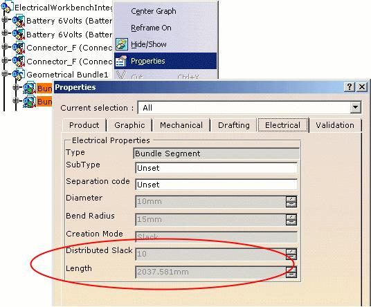
138 Page 138


139 Viewing Related Objects Page 139 This task shows how to use the Related Objects viewer to navigate through the objects connected to the selected object. You can focus on an object and see how it was constructed via its related objects. The related objects command identifies the parent, any children or connected objects and the relationship between objects. It is available when none of the icons of the workbench are activated that is to say when you are in Select command. Accessing related objects can be done in two ways: by clicking the Related Objects icon in the toolbar from the contextual menu, by selecting Related Objects.
140 Page 140 The different options available are: Reframe on selection: reframes the main 3D window on the Related objects selection. Reframe on selection: the main window selection corresponds to the Related objects selection. The main window display is not reframed. Freeze: freezes the contents of the Related objects window. You can still navigate in the main window: the Related objects view will not be updated. Freeze: the Related objects selection corresponds to the main window selection. View related objects: displays the parent, any children or connected objects. View related objects: only displays the selected objects. Functional: displays the functional system. If the bundle segment contains wires, the corresponding signals are displayed in the bundle segment. N.B.: the signal name is displayed followed by the separation code, if any: Functional: hides the functional children elements. Wire: displays the wires contained in the bundle segment. Wire: hides the wires contained in the bundle segment, shows the bundle segments and signals. Harness: displays the relationship to the harness: connectors, equipments, shells, etc.
141 Page 141 Harness: hides the children bundle segments, only shows the signals and wires. Sub objects: displays the electrical contents. Sub objects: hides the electrical contents. On a complex electrical system, the 3D view allows you to limit display to a specific area thus enlightening the information regarding this area. Open the RelatedObjectsSession.CATProduct document.

142 Page Select an object: Geometrical Bundle1.1 for example. 2. Click the Related Objects icon. The Related Objects dialog box appears. The geometry area and the specification tree are reframed on the object selected. 3. Select the Bundle Segment4.1 in this window. The dialog box focuses on the object selected: Bundle Segment4.1 (center of the window) and shows the parent and the connected objects: on the left is the parent object (Assembly meaning). It represents the container object. on the right are the children objects (Assembly meaning), connected to the Bundle Segment4.1. They represent the contents.

143 Page 143 This window shows the following: the bundle segments assembly within the geometrical bundle the Bundle Segment4.1 is connected to three bundle segments the Bundle Segment4.1 contains two wires and their associated signal. 4. Select the Sig2. The geometry area is reframed on the signal and it shows: the signal extremities with the functional connectors the wire that realizes the signal the harness objects: the physical connectors that correspond to the signal extremities as well as the bundle segments, and the wire they contain. 5. Click the 3D tab to display the geometry.
144 Page Close the dialog box to exit the Related Objects viewer.
145 Electrical and Knowledge Page 145 This section exposes the functions and objects available in the Knowledge Products. Electrical User Functions Electrical Package in Knowledge Expert

146 Electrical User Functions in Knowledge Products Page 146 DistanceWireProduct is a new function. About the Electrical User Functions... ElecDistanceCommon DistanceWireProduct To be able to use these functions, you need to activate the Electrical Measure package. To do so: 1. Select Tools -> Options... -> General -> Parameters and Measures and go to the Language tab. 2. Choose Electrical Measure and click the right arrow: 3. Click OK to validate. ElecDistanceCommon Syntax ElecDistanceCommon(Wire1: Wire, Wire2: Wire):Length Returns the common length of the two wires given as input arguments. The type of Wire1 and Wire2 is ElecWire. Example 1 The ElecDistanceCommon user function can be used in Knowledge Expert to find all the couples of wires in the session that have a common length greater than a given value.


147 Page 147 Example 2 In Knowledge Advisor, it can be used to define a rule giving the common length of two specific wires sharing properties. Applying the rule displays the following message if the condition is met:


148 Example 3 Page 148 Still in Knowledge Advisor, to verify that two wires selected in the specification tree have a common length, the following action can be defined: then ran: select two wires in the specification tree and click OK to validate. The following message displays: DistanceWireProduct


149 Syntax Page 149 DistanceWireProduct(Wire1: Wire, Object: Product):Length Returns the minimum length between a wire and a product in session. The product must contain at least one part. Example 1 The DistanceWireProduct user function can be used with the f(x) command to display the distance between a wire and a component in the session. This formula returns the following value: Example 2

150 Page 150 The DistanceWireProduct user function can be used in Knowledge Expert to find all the wires in the session that have a minimum distance to defined components smaller than a critical value chosen by the user. The components can be defined as heat-resistant. Properties have been added to the product: and to the wires: A check is defined as follows:


151 Page 151 Updating the session displays green/red light on the check: A report is generated showing the check result: some wires verify the condition, other not. Example 3 The DistanceWireProduct user function can be used in Knowledge Advisor to define a rule that displays a warning message if a minimum distance between a wire and an object is smaller than a critical value chosen by the user.


152 Page 152 Running this rule displays the following message: Example 4 Still in Knowledge Advisor, an action can be defined using the DistanceWireProduct user function, to know the distance between a wire and an object selected in the specification tree: Run the action using the Action.1 contextual menu: select a wire and a product in the specification tree then validate.

153 Page 153 This message displays:
154 Electrical Package in Knowledge Expert Page 154 An Electrical package is supported by Knowledge Expert. This package can be accessed via the object browser and objects, attributes and methods in the package can be used in expert relations. You can, for example, write a rule to report in a file all the bundle segments with a diameter greater than a specified value. The package contains the following objects: The attribute IsSingleInBundleSegment has been added to the Wire object. BackShell FillerPlug SignalRoute BundlePositionPoint FunctionalConnector Stud Bundle FunctionalEquipment System BundleSegment GroundSignal Tape Cavity GroupSignal TerminalBlock CommandSignal InternalSplice TerminalStrip ConnectorShell OffSheet Termination Contact PowerSignal Termination_GeoConstraint ContactPoint Protection VideoSignal CorrugatedTube ShieldingSignal Wire Equipment SingleConnector ExternalSplice Signal BackShell Description Describes the electrical feature of Back Shell type that you create when you select the Electrical Library workbench. For more information, refer to the Electrical Library User's Guide. icon in the The back shell is a physical component used to guide the bundle segment extremity to the single insert connector, and to protect the crimping area. Inheritance path: Standard - Feature -> ProductPackage - Product Attributes Elec_Extra_Length Type: Double
155 Page 155 Defines the cable extra-length to be added to take into account the wire length inside the back shell. Elec_Ref_Des Type: String Defines the back shell reference designator attribute, which is the unique identifier for the back shell in the project. Elec_Sub_Type Type: String Defines the back shell subtype (User defined subtype). Elec_Fmbd_Modify Type: Boolean Defines the back shell attribute, which makes it possible to know if the component has been modified during the Electrical Harness Flattening Synchronization command. Is True if modified. Elec_External_Reference Type: String Defines the back shell external reference attribute. It is used in Electrical Harness Flattening for 2D detail graphic replacement in a drawing. Elec_FullConnected Type: Boolean Is True if the back shell is connected to a single insert connector and a bundle segment. BundlePositionPoint Description Describes the electrical feature of Bundle Segment Position Point type. For more information, refer to the Electrical Harness Installation User's Guide. The Bundle Segment Position Point type defines the point along a bundle segment at which the local slack is applied. Inheritance path: Standard - Feature Attributes Elec_Slack Type: Double Defines the slack length at the bundle segment position point. Bundle Description
156 Page 156 Describes the electrical feature of Bundle type that you create when you click the Wire Routing workbench. For more information, refer to the Electrical Wire Routing User's Guide. icon in the Electrical The ElecBundle type is an object that contains wires. Inheritance path: Standard - Feature -> ProductPackage - Product Attributes Elec_Ref_Des Type: String Defines the bundle reference designator attribute, which is the unique identifier for the bundle in the project. Elec_Sub_Type Type: String Defines the bundle subtype (User defined subtype). BundleSegment Description Describes the electrical feature of Bundle Segment type that you create when you select the Electrical Harness Installation workbench. For more information, refer to the Electrical Harness Installation User's Guide. icon in the The BundleSegment type is a segment of a geometrical bundle. Inheritance path: Standard - Feature -> ProductPackage - Product Attributes Elec_Bend_Radius Type: Double Input data defining the bend radius value that corresponds to the minimum bend radius of the bundle segment curve. Elec_Bend_Radius_OK Type: Boolean Is True if the bundle segment real bend radius is greater than the Elec_Bend_Radius attribute. Elec_Creation_Mode Type: String
157 Page 157 Defines the electrical bundle segment creation mode. Three modes exist: Slack: Elec_Length is not valuated. Bend: Elec_Slack and Elec_Length are not valuated. Length: Elec_Slack is not valuated. Elec_Di_Slack Type: Double Input data defining the percentage of distributed slack along the bundle segment. This attribute induces the value of the Elec_Length attribute. Elec_Diameter Type: Double Defines the bundle segment diameter. Elec_Fmbd_Modify Type: Boolean Defines the bundle segment attribute, which makes it possible to know if the component has been modified during the Electrical Harness Flattening Synchronization command. Is True if modified. Elec_FullConnected Type: Boolean Is True if both bundle segment extremities are connected. Elec_Length Type: Double Defines the bundle segment length. Elec_Ref_Des Type: String Defines the bundle reference designator attribute, which is the unique identifier for the bundle in the project. Elec_Segreg Type: String Defines the bundle segment separation code used by the routing algorithm. Elec_Sub_Type Type: String Defines the bundle segment subtype. Elec_True_Length Type: Double Output data valuated by the routing algorithm at the creation of the bundle segment in Slack or Bend mode. It defines the bundle segment length. Cavity Description
158 Page 158 Describes the electrical feature of Cavity type that you create when you click this icon Library workbench. For more information, refer to the Electrical Library User's Guide. in the Electrical The cavity defines a reservation for a connector. Inheritance path: Standard - Feature -> ProductPackage - Product Attributes Elec_Extra_Length Type: Double Defines the wire length to be added to the wire routing length. Elec_Id_Number Type: String Defines a unique identifier for the cavity used to map a functional component and the corresponding physical part. Elec_Ref_Des Type: String Defines the cavity reference designator attribute, which is the unique identifier for the cavity in the project. Elec_Sub_Type Defines the cavity subtype. Type: String CommandSignal Description Describes the electrical feature of Command Signal type that you create when you click this icon Electrical System Functional Definition workbench. For more information, refer to the Electrical System Functional Definition User's Guide. in the The command signal is a logical connection between two or more components. It will be realized by a wire in physical world. Inheritance path: Standard - Feature -> ProductPackage - Product -> Electrical - ElecSignal Attributes Elec_Nominal_Part_Num Type: String Defines the nominal part number of the wire that realizes the command signal. Elec_Recom_Wire_Type Type: String
159 Page 159 Defines the attribute of the wire recommended to realize the signal. Elec_Routing_Priority Type: Double Defines the priority for the signal routing. Elec_Sep_Code Type: String Defines the separation code of the command signal used by the algorithm to find out the wire route. Elec_Signal_Section Defines the command signal section. Type: Double Elec_Sub_Type Defines the command signal subtype. Type: String ConnectorShell Description Describes the electrical feature of Connector-Shell type that you create when you click the Electrical Library workbench. For more information, refer to the Electrical Library User's Guide. icon in the A connector shell or shell is a non-electrical part which groups one or more electrical connector parts. It may be part of an equipment. Inheritance path: Standard - Feature -> ProductPackage - Product Attributes Elec_Ref_Des Type: String Defines the connector shell reference designator attribute, which is the unique identifier for the connector shell in the project. Elec_Sub_Type Type: String Defines the connector shell subtype. Elec_Fmbd_Modify Type: Boolean Defines the connector shell attribute, which makes it possible to know if the component has been modified during the Electrical Harness Flattening Synchronization command. Is True if modified. Elec_External_Reference Type: String
160 Page 160 Defines the connector shell external reference attribute. It is used in Electrical Harness Flattening for 2D detail graphic replacement in a drawing. Contact Description Describes the electrical feature of Contact type that you create when you click the Library workbench. For more information, refer to the Electrical Library User's Guide. icon in the Electrical A contact is an electrical component used within a termination and a cavity or between bundle segments. Inheritance path: Standard - Feature -> ProductPackage - Product Attributes Elec_Barrel_Diameter Type: Double Defines the hole diameter which lets the wire through. Elec_External_Reference Type: String Defines the contact reference from an external library. Elec_FullConnected Type: Boolean Is True if all the contacts are connected. Elec_Ref_Des Type: String Defines the contact reference designator attribute, which is the unique identifier for the contact in the project. Elec_Sub_Type Defines the contact subtype. Type: String CorrugatedTube Description
161 Page 161 Describes the electrical feature of Corrugated Tube type that you create when you click the icon in the Electrical Library workbench. The corrugated tube is then instantiated using the Electrical Harness Installation workbench. For more information, refer to the Electrical Library and Electrical Harness Installation User's Guides. A corrugated tube is an electrical component applied onto bundle segments as a protection. Inheritance path: Standard - Feature -> ProductPackage - Product Attributes Elec_Bend_Radius Type: Double Defines the bend radius value, which corresponds to the minimum bend radius of the corrugated tube curve. Elec_Bend_Radius_Protection_OK Type: Boolean Is True if the Elec_Bend_Radius attribute is smaller than the real value of bend radius of the largest bundle segment linked to the corrugated tube. Elec_Fmbd_Modify Type: Boolean Defines the single connector attribute, which makes it possible to know if the component has been modified during the Electrical Harness Flattening Synchronization command. Is True if modified. Elec_Inner_Diameter Defines the corrugated tube inner diameter. Type: Double Elec_Length Defines the corrugated tube length. Type: Double Elec_Line_Type Defines the corrugated tube line type. Type: Double Elec_Line_Weight Type: Double Defines the corrugated tube linear mass, used for the flattened representation. Elec_Ref_Des Type: String Defines the corrugated tube reference designator attribute, which is the unique identifier for the corrugated tube in the project. Elec_Ref_PartNumber Type: String Defines the corrugated tube reference part number. Elec_Sub_Type Type: String
162 Page 162 Defines the protection subtype. Elec_Thickness Defines the corrugated tube thickness. Type: Double Equipment Description Describes the electrical feature of Equipment type that you create when you click the Library workbench. For more information, refer to the Electrical Library User's Guide. icon in the Electrical An equipment is an electrical device with one or more associated components: connectors, shells, contacts, filler plugs, placed in cavities. An equipment can also comprise terminations and bundle connection points. Inheritance path: Standard - Feature -> ProductPackage - Product Attributes Elec_External_Reference Type: String Defines the equipment reference from an external library. It is used in Electrical Harness Flattening for 2D detail graphic replacement in a drawing. Elec_Fmbd_Modify Type: Boolean Defines the equipment attribute, which makes it possible to know if the component has been modified during the Electrical Harness Flattening Synchronization command. Is True if modified. Elec_Ref_Des Type: String Defines the equipment reference designator attribute, which is the unique identifier for the equipment in the project. Elec_Sub_Type Defines the equipment subtype. Type: String ExternalSplice Description
163 Page 163 Describes the electrical feature of External Splice type that you create when you click the Electrical Library workbench. For more information, refer to the Electrical Library User's Guide. icon in the An external splice is an electrical connector receiving bundle segments from different geometrical bundles. Inheritance path: Standard - Feature -> ProductPackage - Product Attributes Elec_External_Reference Type: String Defines the external splice reference from an external library. It is used in Electrical Harness Flattening for 2D detail graphic replacement in a drawing. Elec_Fmbd_Modify Type: Boolean Defines the external splice attribute, which makes it possible to know if the component has been modified during the Electrical Harness Flattening Synchronization command. Is True if modified. Elec_Ref_Des Type: String Defines the external splice reference designator attribute, which is the unique identifier for the external splice in the project. Elec_Sub_Type Type: String Defines the external splice subtype. Elec_FullConnected Type: Boolean Is True if all the bundle connection points and terminations of the external splice are connected. FillerPlug Description Describes the electrical feature of Filler Plug type that you create when you click the Library workbench. For more information, refer to the Electrical Library User's Guide. icon in the Electrical A filler plug is an electrical component used to block up an unused cavity. Inheritance path: Standard - Feature -> ProductPackage - Product Attributes Elec_Ref_Des Type: String
164 Page 164 Defines the filler plug reference designator attribute, which is the unique identifier for the filler plug in the project. Elec_Sub_Type Type: String Defines the filler plug subtype. ContactPoint Description Describes the electrical feature of Contact Point type that you create when you select the Electrical System Functional Definition workbench. For more information, refer to the Electrical System Functional Definition User's Guide. icon in the This contact point is a functional electrical component that defines the point of contact or attachment for an electrical signal. Inheritance path: Standard - Feature -> ProductPackage - Product Attributes Elec_Id_Number Type: String Defines the contact point Id number. Elec_Number Type: Integer Defines a unique identifier for the contact point used to map a functional component and the corresponding physical part. Elec_Ref_Des Type: String Defines the contact point reference designator attribute, which is the unique identifier for the contact point in the project. Elec_Signal_IO Type: String Defines if the signal is input or output. Elec_Signal_Unicity Type: Boolean Defines the unicity of the signal: True if the signal is unique. Elec_Sub_Type Type: String Defines the contact point subtype.
165 Page 165 FunctionalConnector Description Describes the electrical feature of Functional Connector type that you create when you click the Electrical System Functional Definition workbench. For more information, refer to the Electrical System Functional Definition User's Guide. icon in the This connector is a functional electrical component with one or more associated contact points, for example, a power or signal transmission connector. Inheritance path: Standard - Feature -> ProductPackage - Product Attributes Elec_External_Reference Type: String Defines the functional connector reference to an external library. Elec_Id_Number Type: String Defines a unique identifier for the functional connector used to map a functional component and the corresponding physical part. Elec_Nominal_Part_Num Type: String Defines the nominal part number of the physical connector that realizes the functional connector. Elec_Ref_Des Type: String Defines the functional connector reference designator attribute, which is the unique identifier for the connector in the project. Elec_Sub_Type Type: String Defines the functional connector subtype. FunctionalEquipment Description
166 Describes the electrical feature of Functional Equipment type that you create when you click the Electrical System Functional Definition workbench. For more information, refer to the Electrical System Functional Definition User's Guide. Page 166 icon in the This equipment is a functional electrical component with one or more associated connectors, for example a lamp or a battery. Inheritance path: Standard - Feature -> ProductPackage - Product Attributes Elec_External_Reference Type: String Defines the functional equipment reference to an external library. Elec_Nominal_Part_Num Type: String Defines the nominal part number of the physical equipment that realizes the functional equipment. Elec_Ref_Des Type: String Defines the functional equipment reference designator attribute, which is the unique identifier for the equipment in the project. Elec_Sub_Type Type: String Defines the functional equipment subtype. GroundSignal Description Describes the electrical feature of Ground Signal type that you create when you click this icon Electrical System Functional Definition workbench. For more information, refer to the Electrical System Functional Definition User's Guide. in the The ground signal is a logical connection between two or more components. It will be realized by a wire in physical world. Inheritance path: Standard - Feature -> ProductPackage - Product -> Electrical - ElecSignal Attributes Elec_Ground_Unicity Type: Boolean Defines the unicity of the ground signal: True if the signal is unique. Elec_Nominal_Part_Num Type: String
167 Page 167 Defines the nominal part number of the wire that realizes the ground signal. Elec_Recom_Wire_Type Type: String Defines the attribute of the wire recommended to realize the signal. Elec_Routing_Priority Type: Double Defines the priority for the signal routing. Elec_Sep_Code Type: String Defines the separation code of the ground signal used by the algorithm to find out the wire route. Elec_Signal_Section Defines the ground signal section. Type: Double Elec_Sub_Type Defines the ground signal subtype. Type: String GroupSignal Description Describes the electrical feature of Group Signal type that you create when you click this icon Electrical System Functional Definition workbench. For more information, refer to the Electrical System Functional Definition User's Guide. in the Groups signals will be routed together, for example shielded or twisted signals. Inheritance path: Standard - Feature -> ProductPackage - Product -> Electrical - ElecSignal Attributes Elec_Nominal_Part_Num Type: String Defines the nominal part number of the wire that realizes the group signal. Elec_Recom_Wire_Type Type: String Defines the attribute of the wire recommended to realize the signal. Elec_Routing_Priority Type: Double Defines the priority for the signal routing. Elec_Sep_Code Type: String
168 Page 168 Defines the separation code of the group signal used by the algorithm to find out the wire route. Elec_Signal_Section Defines the group signal section. Type: Double Elec_Fmbd_Modify Type: Boolean Defines the internal splice attribute, which makes it possible to know if the component has been modified during the Electrical Harness Flattening Synchronization command. Is True if modified. Elec_Sub_Type Defines the group signal subtype. Type: String InternalSplice Description Describes the electrical feature of Internal Splice type that you create when you click the Electrical Library workbench. For more information, refer to the Electrical Library User's Guide. icon in the An internal splice is a type of connector used to connect two or more wires belonging to the same bundle. Inheritance path: Standard - Feature -> ProductPackage - Product Attributes Elec_External_Reference Type: String Defines the internal splice reference to an external library. It is used in Electrical Harness Flattening for 2D detail graphic replacement in a drawing. Elec_Mass Defines the internal splice mass. Type: Double Elec_Offset Type: Double Defines the distance to the bundle segment extremity selected to place the internal splice. Elec_Ref_Des Type: String Defines the internal splice reference designator attribute, which is the unique identifier for the internal splice in the project. Elec_Sub_Type Type: String
169 Page 169 Defines the internal splice subtype. OffSheet Description Describes the electrical feature of Off Sheet Connector type that you create when you click the Electrical System Functional Definition workbench. For more information, refer to the Electrical System Functional Definition User's Guide. icon in the An off sheet connector is a marker in the functional definition that is used to establish connections between different systems. Inheritance path: Standard - Feature -> ProductPackage - Product Attributes Elec_Name Defines the off sheet connector name. Type: String Elec_Number Defines the off sheet connector number. Type: Integer Elec_Signal_IO Defines if the signal is input or output. Type: String Elec_Sub_Type Defines the off sheet connector subtype. Type: String Stud Description Describes the electrical feature of Stud type that you create when you click this icon Library workbench. For more information, refer to the Electrical Library User's Guide. in the Electrical A stud is an electrical connector receiving bundle segments with one or more wires connected through a termination. It is used to ground bundle segments or pieces of equipment. Inheritance path: Standard - Feature -> ProductPackage - Product
170 Attributes Elec_External_Reference Type: String Defines the stud reference to an external library. It is used in Electrical Harness Flattening for 2D detail graphic replacement in a drawing. Page 170 Elec_Ref_Des Type: String Defines the stud reference designator attribute, which is the unique identifier for the stud in the project. Elec_Sub_Type Defines the stud subtype. Type: String Elec_FullConnected Type: Boolean Is True only if all the stud bundle connection points are connected. PowerSignal Description Describes the electrical feature of Power Signal type that you create when you click this icon Electrical System Functional Definition workbench. For more information, refer to the Electrical System Functional Definition User's Guide. in the The power signal is a logical connection between two or more components. It will be realized by a wire in physical world. Inheritance path: Standard - Feature -> ProductPackage - Product -> Electrical - ElecSignal Attributes Elec_Nominal_Part_Num Type: String Defines the nominal part number of the wire that realizes the power signal. Elec_Nominal_Voltage Type: Double Defines the power signal nominal voltage. Elec_Recom_Wire_Type Type: String Defines the attribute of the wire recommended to realize the signal. Elec_Routing_Priority Type: Double Defines the priority for the signal routing.
171 Page 171 Elec_Sep_Code Type: String Defines the separation code of the power signal used by the algorithm to find out the wire route. Elec_Sub_Type Defines the power signal subtype. Type: String Elec_Signal_Section Defines the power signal section. Type: Double Protection Description Describes the electrical feature of protection type from which both the corrugated tube and the tape derives. For more information, refer to the Electrical Library and Electrical Harness Installation User's Guides. Inheritance path: Standard - Feature -> ProductPackage - Product Attributes Elec_Length Defines the protection length. Type: Double Elec_Line_Type Defines the protection line type. Type: Double Elec_Line_Weight Type: Double Defines the protection linear mass, used for the flattened representation. Elec_Ref_Des Type: String Defines the protection reference designator attribute. Elec_Ref_PartNumber Type: String Defines the protection reference part number. Elec_Sub_Type Defines the protection subtype. Type: String ShieldingSignal
172 Page 172 Description Describes the electrical feature of Shielding Signal type that you create when you click this icon Electrical System Functional Definition workbench. For more information, refer to the Electrical System Functional Definition User's Guide. in the The shielding signal is a logical connection between two or more components. It will be realized by a wire in physical world. Inheritance path: Standard - Feature -> ProductPackage - Product -> Electrical - ElecSignal Attributes Elec_Nominal_Part_Num Type: String Defines the nominal part number of the wire that realizes the shielding signal. Elec_Recom_Wire_Type Type: String Defines the attribute of the wire recommended to realize the signal. Elec_Routing_Priority Type: Double Defines the priority for the signal routing. Elec_Sep_Code Type: String Defines the separation code of the shielding signal used by the algorithm to find out the wire route. Elec_Sub_Type Defines the shielding signal subtype. Type: String Elec_Signal_Section Defines the shielding signal section. Type: Double Elec_Nominal_Voltage Type: Double Defines the shielding signal nominal voltage. SingleConnector Description
173 Page 173 Describes the electrical feature of Single Insert Connector type that you create when you click this icon the Electrical Library workbench. For more information, refer to the Electrical Library User's Guide. in A single insert connector is an electrical connector male or female. It's the physical representation for both the plugs and the sockets. Inheritance path: Standard - Feature -> ProductPackage - Product Attributes Elec_External_Reference Type: String Defines the single insert connector reference to an external library. It is used in Electrical Harness Flattening for 2D detail graphic replacement in a drawing. Elec_Ref_Des Type: String Defines the single insert connector reference designator attribute, which is the unique identifier for the single insert connector in the project. Elec_Sub_Type Type: String Defines the single insert connector subtype. Elec_Fmdb_Modify Type: Boolean Defines the single connector attribute, which makes it possible to know if the component has been modified during the Electrical Harness Flattening Synchronization command. Is True if modified. Elec_FullConnected Is True in only two cases: Type: Boolean if the single insert connector is integrated into an equipment and connected to another single insert connector, if the single insert connector is connected to a bundle segment or a back shell and connected to another single insert connector. Signal Description
174 Page 174 Describes the electrical feature of Signal type that you create when you click the icon in the Electrical System Functional Definition workbench. For more information, refer to the Electrical System Functional Definition User's Guide. A signal is a logical connection between two or more components. May be of the following types: ground, shielding, video, power, command or grouped. Inheritance path: Standard - Feature -> ProductPackage - Product Attributes Elec_Nominal_Part_Num Type: String Defines the nominal part number of the physical wire that realizes the signal. Elec_Recom_Wire_Type Type: String Defines the attribute of the wire recommended to realize the signal. Elec_Routing_Priority Defines the priority for the signal routing. Type: Double Elec_Sep_Code Type: String Defines the separation code of the signal used by the algorithm to find out the wire route. Elec_Signal_Section Defines the signal section. Type: Double Elec_ListPhysical Type: CATIList Contains the list of ElecWire objects that realize the signal. SignalRoute Description Describes the electrical feature of Signal Route type that you create when you click this icon Electrical Wire Routing workbench. For more information, refer to the Electrical Wire Routing User's Guide. in the The signal route is computed to find out the optimized way between two or more extremities of a signal. Inheritance path: Standard - Feature Attributes
175 Page 175 Elec_Length Defines the signal route length. Type: Double Elec_Nominal_Part_Num Type: String Defines the nominal part number of the wire that realizes the signal. Elec_Section Defines the signal route section. Type: Double Elec_Sub_Type Defines the signal route subtype. Type: String System Description Describes the electrical feature of System type that you create when you click the icon in the Electrical System Functional Definition workbench. For more information, refer to the Electrical System Functional Definition User's Guide. A system consists of equipments, connectors and signals. It is an electrical unit, which accomplishes a specific function. Inheritance path: Standard - Feature -> ProductPackage - Product Attributes Elec_Ref_Des Type: String Defines the system reference designator attribute, which is the unique identifier for the system in the project. Elec_Sub_Type Type: String Defines the system subtype. Tape Description
176 Page 176 Describes the electrical feature of Tape type that you create when you click the icon in the Electrical Library workbench. The tape is then instantiated using the Electrical Harness Installation workbench. For more information, refer to the Electrical Library and Electrical Harness Installation User's Guides. A tape is an electrical component applied onto bundle segments as a protection. Inheritance path: Standard - Feature -> ProductPackage - Product Attributes Elec_Bend_Radius_Delta Type: Double Defines the bend radius value, which corresponds to the minimum bend radius of the tape curve. This value takes into account the bundle segment and tape bend radius rule and ends up to an increased rigidity due to the tape. Elec_Bend_Radius_Protection_OK Type: Boolean Is True if the Elec_Bend_Radius attribute is smaller than the real value of bend radius of the largest bundle segment linked to the tape protection. Elec_Covering_Length Type: Double Defines the tape overlapping used when instantiating the protection. Elec_Fmbd_Modify Type: Boolean Defines the bundle segment attribute, which makes it possible to know if the component has been modified during the Electrical Harness Flattening Synchronization command. Is True if modified. Elec_Length Defines the tape length. Type: Double Elec_Line_Type Type: Double Defines the tape line type, used for the flattened representation. Elec_Line_Weight Defines the tape linear mass. Type: Double Elec_Number_Layer Type: Double Defines the tape number of layers applied onto the bundle segment. Elec_Ref_Des Type: String Defines the tape reference designator attribute, which is the unique identifier for the tape in the project. Elec_Ref_PartNumber Type: String
177 Page 177 Defines the tape reference part number. Elec_Sub_Type Defines the protection subtype. Type: String Elec_Tape_Thickness Defines the tape thickness. Type: Double Elec_Tape_Width Defines the tape width. Type: Double Elec_Taping_Angle Defines the taping angle. Type: Double Elec_Total_Tape_Length Type: Double Defines the tape length considering the overlapping due to the taping angle, and also the number of layers. Elec_Total_Thickness Type: Double Defines the tape thickness considering the overlapping due to the taping angle, and also the number of layers. TerminalBlock Description Describes the electrical feature of Terminal Block type that you create when you select this icon Electrical Library workbench. For more information, refer to the Electrical Library User's Guide. in the A terminal block is an electrical connector receiving bundle segments, each bundle segment being connected to a termination. Inheritance path: Standard - Feature -> ProductPackage - Product Attributes Elec_External_Reference Type: String Defines the terminal block reference to an external library. It is used in Electrical Harness Flattening for 2D detail graphic replacement in a drawing. Elec_Fmbd_Modify Type: Boolean
178 Page 178 Defines the terminal block attribute, which makes it possible to know if the component has been modified during the Electrical Harness Flattening Synchronization command. Is True if modified. Elec_Ref_Des Type: String Defines the terminal block reference designator attribute, which is the unique identifier for the terminal block in the project. Elec_Sub_Type Type: String Defines the terminal block subtype. Elec_FullConnected Type: Boolean Is True if all the terminal block terminations are connected. Termination Description Describes the electrical feature of Termination type that you create when you click this icon Electrical Library workbench. For more information, refer to the Electrical Library User's Guide. in the A termination is a sub-element ensuring the electrical signal conduction between any type of electrical component except the filler plug. It is indissociable from the electrical component and corresponds to a contact crimped into a cavity. Inheritance path: Standard - Feature -> ProductPackage - Product Attributes Elec_Extra_Length Type: Double Defines the length to be added to the wire routing length. Elec_Id_Number Type: String Defines a unique identifier for the termination used to map a functional component to the corresponding physical part. Elec_Ref_Des Type: String Defines the termination reference designator attribute, which is the unique identifier for the termination in the project. Elec_Sub_Type Type: String
179 Page 179 Defines the termination subtype. Termination_GeoConstraint Description Describes the electrical feature of Termination type that you create when you click this icon Electrical Library workbench. For more information, refer to the Electrical Library User's Guide. in the This type of termination only exists for terminal strip and the stud connectors. It has an associated geometry (a line), which allows the connection to be constrained between the bundle segment and the connector. The bundle segment can only be connected via this associated geometry (the line). Inheritance path: Standard - Feature -> ProductPackage - Product Attributes Elec_Extra_Length Type: Double Defines the length to be added to the wire routing length. Elec_Id_Number Type: String Defines a unique identifier for the termination used to map a functional component and the corresponding physical part. Elec_Ref_Des Type: String Defines the termination reference designator attribute, which is the unique identifier for the termination in the project. Elec_Sub_Type Type: String Defines the termination subtype. TerminalStrip Description
180 Page 180 Describes the electrical feature of Terminal Strip type that you create when you click this icon Electrical Library workbench. For more information, refer to the Electrical Library User's Guide. in the A terminal strip is an electrical connector comprising a strip of terminations. Inheritance path: Standard - Feature Attributes Elec_External_Reference Type: String Defines the terminal strip reference to an external library. It is used in Electrical Harness Flattening for 2D detail graphic replacement in a drawing. Elec_Fmbd_Modify Type: Boolean Defines the terminal strip attribute, which makes it possible to know if the component has been modified during the Electrical Harness Flattening Synchronization command. Is True if modified. Elec_Ref_Des Type: String Defines the terminal strip reference designator attribute, which is the unique identifier for the terminal strip in the project. Elec_Sub_Type Defines the terminal strip subtype. Type: String Elec_FullConnected Type: Boolean Is True if all the terminal strip terminations are connected. VideoSignal Description Describes the electrical feature of Video Signal type that you create when you click this icon Electrical System Functional Definition workbench. For more information, refer to the Electrical System Functional Definition User's Guide. in the The video signal is a logical connection between two or more components. It will be realized by a wire in physical world. Inheritance path: Standard - Feature -> ProductPackage - Product -> Electrical - ElecSignal Attributes Elec_Nominal_Part_Num Type: String
181 Page 181 Defines the part number of the wire that realizes the video signal. Elec_Recom_Wire_Type Type: String Defines the attribute of the wire recommended to realize the signal. Elec_Routing_Priority Type: Double Defines the priority for the signal routing. Elec_Sep_Code Type: String Defines the separation code of the video signal used by the algorithm to find out the wire route. Elec_Signal_Section Defines the video signal section. Type: Double Elec_Sub_Type Defines the video signal subtype. Type: String Wire Description Describes the electrical feature of Wire type that you create when you click the Library workbench. For more information, refer to the Electrical Library User's Guide. icon in the Electrical Inheritance path: Standard - Feature -> ProductPackage - Product Attributes Elec_Bend_Radius Defines the bend radius. Type: Double Elec_Catalog Type: String Defines the catalog from which the wire is selected. Elec_Color Defines the color of the wire. Type: String Elec_Diameter Type: Double
182 Page 182 Defines the wire diameter. Elec_FromConnectionPoint Type: String Returns the reference designator value of the connection point to which the first extremity of the wire is connected. Elec_FromDevice Type: String Returns the reference designator value of the device to which the first extremity of the wire is connected. Elec_FullConnected Type: Boolean Is True if both wire extremities are connected. Elec_IsNetworkConnex Type: Boolean Is True if a route exists between whatever nodes only using the network connected branches. Elec_IsRouted Is True if the wire is routed. Type: Boolean Elec_Length Defines the wire length. Type: Double Elec_Line_Weight Defines the wire linear mass. Type: Double Elec_Ref_Des Type: String Defines the wire reference designator. Elec_Sep_Code Type: String Defines the separation code of the wire used by the algorithm to find out the wire route. Elec_Shielding_Signal Type: String Returns a product of type ElecSignal that realizes the wire. Elec_Signal Type: ElecSignal Returns a product of type ElecSignal that realizes the wire. Elec_Signal_Id Type: String Defines the identifier of the signal used during the wire routing.
183 Page 183 Elec_Sub_Type Defines the wire subtype. Type: String Elec_ToConnectionPoint Type: String Returns the reference designator value of the connection point to which the second extremity of the wire is connected. Elec_ToDevice Type: String Returns the reference designator value of the device to which the second extremity of the wire is connected. IsSingleInBundleSegment Type: Boolean Is True when the wire route follows at least one bundle segment containing only this wire.
184 Page 184 Electrical Application Interoperability In this section, you will find information about interoperability between CATIA Electrical Applications and other applications listed below: ENOVIA LCA Interoperability Using ENOVIA Catalog for Electrical Mapping Loading an ixf Document with VPM Navigator

 is the most basic entity in your Product Structure. 3.")
185 ENOVIA LCA Interoperability using VPM Navigator Page 185 This task explains how to work with electrical data stored in ENOVIA, using VPM Navigator. We recommend that you read the VPM Navigator User's Guide to know more about this product. This documentation can be found on the ENOVIA LifeCycle Applications Documentation CDROM. 1. Log on to VPM Navigator. Once the connection has completed successfully, the icons in the ENOVIA toolbar are no longer grayed out. 2. Click the the Search ENOVIA data button in the ENOVIA toolbar. The Result window listing all the PRCs appears. A PRC (referred to in VPM Navigator as the Product Root Class or root) is the most basic entity in your Product Structure. 3. In this window, double-click the object you want to open. The VPM Navigator window displays, looking something like this: You are now ready to work with this ENOVIA data. 4. Click the Close button if you no longer need the Result window.
186 Page 186 Working with Electrical Data This task shows you how to open electrical objects for editing purposes. Electrical data can be saved in product document (in workpackage) or in component (in explode mode): Geometrical bundles can be saved with both these modes, when CATPart documents (bundle segments, devices, etc.) and electrical bundles can only be saved as workpackage. 1. In the Product tree, right-click the object you want to open and, in the contextual menu, select the Open... command. Note that the multi-selection is possible using the Ctrl-key. The following dialog box appears:

187 Page Click OK to open the documents in context. 3. Now switch to Electrical Library to connect the plug of the geometrical bundle to the female socket of the other. To do so:
188 Page 188 a. Click the Connect Electrical Devices button. b. Select the female socket. c. Select the plug. For more information about electrical device connections, refer to Electrical Library User's Guide - User Tasks - Connecting Electrical Devices. The bundle segment of the second geometrical bundle is updated. 4. Click Save in ENOVIA V5 to store your data in ENOVIA V5. Also refer to Working with ENOVIA LCA: Optimal CATIA PLM Usability.

189 Working with ENOVIA LCA: Optimal CATIA PLM Usability Page 189 This section explains in more details how electrical data designed in CATIA is stored in ENOVIA LCA, using VPM Navigator. And this being user-friendly. When working with ENOVIA LCA, a new mode ensures that you only create data in CATIA that can be correctly saved in ENOVIA LCA. ENOVIA LCA offers two different storage modes: Workpackage (Document kept - Publications Exposed) and Explode (Document not kept). Electrical products have been configured to work in the Workpackage mode and the Explode mode, according to the objects considered. We recommend that you read the VPM Navigator User's Guide to know more about this product. This documentation can be found on the ENOVIA LifeCycle Applications Documentation CDRom. Working with Geometrical Bundle as Workpackage A workpackage is a set of documents that are stored in ENOVIA LCA as a single entity. This means that a node in CATIA specification tree is chosen as an entity to be shown in ENOVIA LCA. The children are not visible as documents in ENOVIA LCA. The geometrical bundle is a candidate to be stored this way, as it represents a complete and coherent package for the electrical design. Within CATIA connected to ENOVIA LCA through VPM Navigator, if the user selects a new product as a geometrical bundle, the system automatically knows that this geometrical bundle has to be stored as a workpackage. Checks are performed when using the Electrical tools to ensure that all entities created or modified will be correctly stored, using the following rules:
190 Page 190 No links to geometry (that is to say external references) can be done from the part inside a workpackage to a part outside the workpackage. The context for the external links must be set to a product node inside the workpackage. Refer to Infrastructure User's Guide - Customizing Part Infrastructure. Mechanical constraints and electrical connections between parts inside the workpackage and outside the workpackage must rely on published objects. To make this possible, the following settings must be applied when working with CATIA connected to ENOVIA LCA, to store the geometrical bundles as workpackage in ENOVIA LCA: a. Select Tools -> Options -> Infrastructure -> Part Infrastructure -> General tab. In the External References frame, uncheck Use root context in assembly. b. Select Tools -> Options -> Equipment and Systems -> Electrical Harness Installation -> Harness Management tab. In the Contextual Links frame, for Keep link with selected object, choose In geometrical bundle in the list. Anyway, the system checks that the rules are not violated and if those options are not set properly, an error message is displayed:

191 Page 191 Moreover, during the electrical connection between devices and/or bundle segments that are not inside the same workpackage, publications are automatically created on the geometrical bundle stored as workpackage, to ensure that constraints and connections are correctly stored. Working with Geometrical Bundle in Explode Mode Using the Explode mode, all the nodes of the product structure are stored in ENOVIA LCA. This means that each component and its children are as many documents visible in ENOVIA LCA. Within CATIA connected to ENOVIA LCA through to VPM Navigator, if the user selects a new component as a geometrical bundle, the system automatically knows that this geometrical bundle has to be stored in explode mode. A single check is performed when using the Electrical tools to ensure that all the entities created or modified will be correctly stored: The context for the external links must be set to the root product node of the session. Refer to Infrastructure User's Guide - Customizing Part Infrastructure. To make this possible, the following settings must be applied when working with CATIA connected to ENOVIA LCA, to store the geometrical bundles in explode mode in ENOVIA LCA:

192 Page 192 a. Select Tools -> Options -> Infrastructure -> Part Infrastructure -> General tab. In the External References frame, check Use root context in assembly. Commands Not Supported in ENOVIA LCA For the time being, the following commands are not available if CATIA is connected to ENOVIA LCA Database: In Electrical Library - Electrical Assembly workbench Place Physical Device Add Link Remove Functional Link Define Mounting Equipment Define Equipment Define Shell Define Contact Define Filler Plug Define Back Shell Define Cavity Define Termination Define Connector Connection Point Define Bundle Connection Point Define Cavity Connection Point Define Back Shell Connection Point In Electrical Wire Routing
193 Page 193 New Wire Connection Move Connection Delete Connection Merge Connections Split Connection New Wire Select Signal

194 Using ENOVIA Catalog for Electrical Mapping Page 194 This methodology explains how to set up the Electrical Mapping option to use catalogs coming from ENOVIA. First of all, the document environment needs to be set up to allow the catalog stored in ENOVIA LCA to be browsed/accessed. Then the catalog of interest is selected in the Electrical Mapping tab. To do so: 1. Select the Tools -> Options command. The Options dialog box displays. 2. Choose the General category in the left-hand box and click the Document tab. This tab lets you define the document environment. 3. Select ENOVIA and click the Allowed button on the right. The Current button is activated. 4. Click the Current button if you want ENOVIA to be launched by default. The dialog box becomes: 5. Make sure you are connected to VPM Navigator. 6. Switch then to the Equipment & Systems category, to the Electrical Mapping tab:
195 Page 195 This tab lets you define the Catalog/Electrical objects mapping. 7. Click the Browse button. The Search ENOVIA data is displayed as follows: Together with:

196 Page Enter one or more criteria and validate. The Search Result window updates. 9. Select the desired catalog and click Open. The Electrical Mapping tab is updated.

197 Page Define the mapping as explained in the CATIA - Infrastructure User's Guide - Customizing - Customizing Settings - Equipment and Systems - Electrical Mapping. The catalogs stored in ENOVIA appears in the editor as ENOVIA5\Catalog name.catalog.
198 Page 198 Loading an ixf Document with VPM Navigator This methodology explains how to load ixf documents when using VPM Navigator. First of all, the document environment needs to be set up to allow the documents stored in ENOVIA LCA to be browsed/accessed. To do so: 1. Make sure you are connected to ENOVIA LCA through VPM Navigator. 2. Click the the Search ENOVIA data button in the ENOVIA toolbar. The Search ENOVIA data is displayed as follows: Together with:

199 Page Enter one or more criteria and validate. For example: documents with ixfelec file extension The Search Result window updates. 4. Select the desired document and open it, using the contextual menu (right-click -> Open item).


200 Page 200 The document is stored in the current session, and ready to use. 5. Switch to Electrical Assembly Design. 6. Click the Select External Systems button. The System Selection dialog box opens containing the previously selected ixf files: 7. Select the ixf file of interest and validate. The ixf document is loaded. For more information about external systems, refer to the CATIA - Electrical Library User's Guide - User Tasks - Electrical Integration Scenarios - Electrical Integration from External Data
201 Workbench Description Page 201 The Electrical Wire Routing Version 5 application window looks like this: Click the hotspots to display the related documentation. Menu Bar Toolbars Specification Tree
202 Menu Bar Page 202 The Menu Bar and most of the items available in Electrical Wire Routing workbench are the standard ones. The different commands and tools are described in Infrastructure Version 5. For more information, refer to the standard Menu Bar section. However an item is added to the Tools menu: Export Wires... Refer to Textual Reports and Exporting Data from CATIA.
203 Electrical Wire Routing Toolbars Page 203 This section describes the various icons available in the Electrical Wire Routing workbench. The toolbars are located on the right in the default set-up except for the Signal which is located in the horizontal bottom toolbar. See Selecting the Signal See Creating Bundle See Routing Simulation See Reconciling Objects See Related Objects See Creating a Connection See Deleting a Connection See Moving a Connection See Merging Connections See Splitting a Connection See Creating a Wire See Routing a Wire, Creating a Signal Route See Routing Equipotentials
204 Page 204 See Modifying a Signal Route See Managing Wire Extremities See Accessing Data From Catalog Using Electrical Library See Filtering Wires See Working with External Data, External Data Exchange
205 Specification Tree Page 205 The Specification Tree displays the following icons: represents an electrical bundle, that is a document containing wires. represents a wire represents a wire associated to a reference (from a catalog) represents a signal route on pathways represents a set of wire connections represents a connection The full set of icons displayed in the electrical workbenches is now available. Also refer to the Product Structure Symbols.
206 Customizing Page 206 Before you start your first working session, you can customize the way you work to suit your habits. This is done using Tools -> Options from the menu bar. This type of customization is stored in permanent setting files: your settings will not be lost if you exit your session. Electrical Wire Routing Electrical Mapping Electrical Process Interfacing Using Compatibility Table Using Knowledgeware Activating the Cache Electrical Data Exchange Format

207 Customizing Electrical Wire Routing Page 207 Before you start your first working session, you can customize the way you work to suit your habits. This is done using Tools -> Options from the menu bar. This type of customization is stored in permanent setting files. Settings will not be lost if you exit your session. 1. Select the Tools -> Options command. The Options dialog box is displayed. 2. Expand the Equipments & Systems in the left-hand box. 3. Click the Electrical Wire Routing workbench. The General tab is displayed: This tab lets you customize: the wire extremities management the property naming to be displayed as a column title the separation code file access the extremity color the bundle segment update mode. 4. Click OK in the dialog box when done.


208 Wire Extremities Management Page 208 The Favorites list contains the properties displayed in the Interconnection frame of the Wire Extremities Management dialog box. To add properties to the list, select the property in the Available list and click the ---> arrow. To remove properties, do the reverse: select the property from the Favorites list and click the <--- arrow. Property Naming Select a property in the Favorites list and enter a name in the Favorite column Title field. It is displayed in the Wire Connection Management dialog box: Separation Code File The Separation Code File area is used to define Separation Code rules to optimize the routing. the separation code is not used. The routing is done according to the shortest route found. It is the default value. the separation codes may be File Based. In that case, define the path to access the compatibility table by clicking the Browse button to choose the separation code file. This file is used during the Automatic Routing and the Routing Simulation. Two options are available: Signal-Signal manages compatibility between signals, Signal-Arc manages compatibility between signal and pathways. the separation codes may also be Rule Based, using CATIA Knowledgeware. Only one rule can be implemented at a time, but this rule may combine several conditions. Click the Edit button to enter a new rule: the Routing Rule Editor is displayed. The line above the input field is a reminder of the knowledgeware syntax. The Eraser icon is used to clear the input field.
209 Extremity Color Page 209 The Extremity Color field is used to change the color of the extremity boxes. Select a color from the combo box. or Bundle Segment Minimum Bend Radius Update Three modes are available: Never: no update of the bundle segment minimum bend radius is performed. Always: the greatest bend radius of the wires routed in the bundle segment determines the segment bend radius to be applied. Conditional: the wire bend radius is taken into account for update when it is greater than the bundle segment bend radius. The default mode is Always.

210 Electrical Mapping Page 210 In order to valuate the keywords automatically when the devices are stored in the catalog with their properties, you need to define a mapping between keywords of each family and the attributes of the component type. 1. Select the Tools -> Options command. The Options dialog box is displayed. 2. Click Equipments & Systems in the left-hand box. 3. Click the Electrical Mapping tab. The tab lets you: define the current catalog using the drop-down list or the Browse button customize the mapping between the catalog and the electrical objects define the keyword attributes. 4. Customize the mapping: associate an electrical type to the currently selected Family.


211 Use the combo list to select the corresponding type. Page Define for each keyword the corresponding reference attribute. The result looks like this: Use the combo list to select the corresponding attribute. 6. Click OK to validate the options. The mapping definition can be set by the administrator. In this case it can also be locked. To get more information about the Administration Mode in CATIA, refer to CATIA - Infrastructure User's Guide.

212 Electrical Process Interfacing Page 212 This document shows how to set up the options to take advantage of external data from partners through XML files or from CAA V5 APIs to get information from legacy databases. Note that the default value for External Data Interfacing is enabled: Enable External System Interfacing is checked. 1. Select the Tools -> Options... command. The Options dialog box is displayed. 2. Click Equipments & Systems category. 3. Click the Electrical Process Interfacing tab. The tab lets you define: the access to external data the electrical ixf repository path the electrical working catalog path the identifier for mapping management. 4. Make sure Enable external systems interfacing is checked.
213 However, you are required to identify the path: of the folder in which the XML files available are stored Page 213 of the working catalog containing the V5 parts which Part Number are referred to in the XML files. 5. Use to locate the ixf systems repository. 6. Use to indicate the catalog path. 7. Check the Instance Name option so that the Instance Name will be taken into account instead of the Reference Designator to insure the mapping between 3D objects and external system's objects. 8. Click OK to validate the options. It is also necessary to define the electrical objects mapping regarding the working catalog. To do so: use the Tools -> Options... menu. then in the Equipment & Systems category, select the Electrical mapping tab. Refer to the Customizing - Equipment & Systems - Electrical mapping documentation.

214 Using Compatibility Table Page 214 The compatibility table contains the list of the separation codes. The separation code is a criterion used as a filter applied to the segments. It is possibly used during the automatic routing: if the separation codes are compatible, the signal can follow the segments whereas, if the separation codes are not compatible, the route is forbidden. This list is organized as follows: to each signal separation code (Segreg-1, Segreg-2, Segreg-3, Segreg-4, Segreg-a) corresponds one or more compatible segment separation codes (type1, type2, type3, type4). The pattern is the following: [Signal Separation Code]: [Compatible Segment Separation Code]; [...]; [Compatible Segment Separation Code]. It looks like this: The first line of the table can be read: Segreg-1 is compatible with type2, type3 and type4. Note that: a signal with an empty separation code can be routed on all the network segments a segment with an empty segregation allows all the signals routing a signal with the same separation code as a segment can be routed on this segment (even with no compatibility table) the separation code of the V4 bundle segments (BNS) can only be modified in CATIA V4 (E3MANAGE/MANAGE/Element)
215 for the pathways, the separation code is modified using Edit -> Properties Page 215 for the signals, the separation code is defined using CATIA - Electrical Systems Functional Definition

216 Using Knowledgeware Page 216 The Separation Code File area is used to define Separation Code rules to optimize the routing. See also Managing Pathway/Signal Compatibility during Automatic Routing with Knowledgeware. The Separation Code may be File Based. In this case, define the path to access the compatibility table by clicking the Browse button to choose the separation code file. This file is used during the Automatic Wire Routing and the Routing Simulation. Two options are available: Signal-Signal manages compatibility between signals, Signal-Arc manages compatibility between signal and pathways. The Separation Code may also be Rule Based, using the Knowledge language. Only one rule can be implemented at a time, but this rule may combine several conditions. 1. Push the Edit button to enter a new rule. The Routing Rule Editor is displayed. The line above the input field is a reminder of the knowledgeware syntax. The Eraser icon is used to clean the input field. 2. Enter the required elements by picking them from the lists. The Rule is now displayed in the option box, using the knowledgeware syntax.

217 Page Click OK when done to exit the Routing Rule Editor. 4. Click OK in the Options dialog box when done.
218 Activating the Cache Page 218 When working with Electrical Wire Routing, it may be useful to activate the cache. Activating the cache allows you to work in visualization mode rather than in design mode. In visualization mode, a representation of the geometry only is available and the corresponding cgr file is inserted from the cache system. Using a cache system considerably reduces the time required to load your data. For more information, refer to Customizing Cache Settings. 1. Select the Tools -> Options... command. The Options dialog box appears. 2. Click Infrastructure -> Product Structure in the left-hand box. 3. Click the Cache Management tab. 4. Turn the cache activation mode on. By default, the activation mode is set to off. 5. When the routing is completed, come back to the design mode. To do so: Turn the cache activation mode off Select Edit -> Representations -> Design Mode 6. Update the geometry using the Update command.
219 Electrical Data Exchange Format Page 219 To complete the end-to-end process, it is possible to get electrical specifications from external data. Those specifications consist of: a device list containing the device attributes and the assembly connectivity and a wire or equipotential list containing their attributes and the from-to connectivity. This information will be used by CATIA Electrical products to implement in the digital mock-up the electrical systems driven by any electrical authoring tool (schematics or database for example). You can either access this information through CAA APIs (refer to CAA documentation) or through an XML file. This method (using an XML file) is described in Electrical Integration from External Data. You will find hereafter the XML schema to create your own interface to CATIA Electrical Tools. The exchange data model is different from the data model of CATIA Electrical solutions. Actually, this data model consists of pertinent information that needs to transit between Electrical specification tools (schematics, etc.) and CATIA. It only aims at implementing those specifications in the mock-up. So only this pertinent information (objects, attributes and connectivity) is described in the following XML schema and not all the information stored in the CATIA electrical product documents. Preamble ixf is a format defined by Dassault Systèmes, which is used for the data exchange in XML within CATIA. Succinctly, ixf is based on the SOAP format and relies on the XML and the XML schema concept. It makes it possible to describe a grammar (a specific data model) expressing the object, class and behavior concepts as well as documents containing data conforming to the defined grammar. A detailed description of the ixf format can be found at the following address: Describing the ixf Electrical Schema Considering the ixf Schema in Greater Depth
220 Describing the ixf Electrical Schema Page 220 The electrical schema, defined for the data exchange between CATIA V5 electrical products and external applications (CAA partners applications, etc.), describes a subset of electrical objects together with their relations. This schema is based on the fact that an object is defined as a class, which one is associated to a behavior set. Thus, an electrical connector corresponds to the Connector class, to which the Connector and Product behaviors are associated. Electrical Objects The following classes with their associated behavior describe the electrical objects within the ixf Electrical Schema. Harness Harness Product Wire Wire Product Equipotential Equipotential Equipment Equipment Product Function ConnectorShell ConnectorShell Product Connector Connector Product Splice Splice Product Pin Pin Product Cavity Cavity All these classes derived from the Object abstract class. This one is not to be used as is but allows you to define the Name attribute for all the classes deriving from the Object class.
221 Page 221 The units for all the attributes are given in the standard MKS system. The following behaviors, associated to the electrical objects are defined in the ixf electrical schema (behavior named ClassBehavior): Harness Attribute: SubType Wire Attributes: InnerDiameter, OuterDiameter (mandatory), BendRadius, Length, Color, LinearMass, SeparationCode, SubType, SignalId Equipment Attribute: SubType ConnectorShell Attribute: SubType Connector Attributes: SubType, Color, MatingConnector Splice Attribute: SubType Pin Attribute: SubType Cavity Attribute: SubType Product Attribute: PartNumber Equipotential Attributes: EstimatedDiameter, SeparationCode, RoutingPriority, WirePartNumber, SubType Function Attributes: System_Type (mandatory if the Function behavior is defined), Description, Localization At last, all the objects expressed in a ixf document have an attribute identifying in a unique way each object within the project, except for the objects of Link type, which have a unique identifier within the document. To illustrate how to describe an electrical object with the ixf format, let's take the example of an electrical connector:
 as subtype: Single Insert Connector (attribute 'SubType' via its Connector behavior) as color: Yellow (attribute 'Color' via its Connector behavior) Relations between Electrical")
222 Page 222 This electrical connector of Connector class has: as identifier: V242 (attribute 'id') as name: Motor,Window_Driver (attribute 'Name') as reference: W (attribute 'PartNumber' via its Product behavior) as subtype: Single Insert Connector (attribute 'SubType' via its Connector behavior) as color: Yellow (attribute 'Color' via its Connector behavior) Relations between Electrical Objects Using a Link type behavior Nearly all the relations between electrical objects take the form of objects with a Link type behavior To know about the standard behavior definition, refer to The Link object classes of the electrical schema are the following: WireLink EquipotentialLink DeviceLink HarnessLink These object classes allow you to define: a. the connectivity of the wire and equipotential objects, that is to say their connections with the electrical components (instantiated standard parts). b. the aggregation relations between the electrical components (instantiated standard parts). For example a connector with pins or an equipment with connectors and pins. c. the harness composition (wires and electrical components) These links take the form of identifiers. For example: a wire, which identifier is W1, connected to two electrical connectors, which identifiers are C1 and C2:
.")

223 Page 223 Using a Specific Attribute The relation between two connectors (mating connector, connector) is not managed by a Link type object as above but using a specific attribute named MatingConnector (behavior attribute of Connector type). This attribute is optional and is valuated with the identifier of the mating connector on both sides of the connection. Let see an example where two connectors are connected together. The connectivity between them is described as follows:
224 Considering the ixf Schema in Greater Depth Page 224 The ixf electrical schema is split in four parts (four files): the first one: ElectricalSchema.xsd refers to the other three and describes the Electrical Object Classes. the second one: IXF_CB_NS1.xsd describes strictly the Electrical Behaviors. the third one: IXF_CB_NS2.xsd describes the Link type Behaviors (ixf standard reference). and last but not least, the fourth one: IXF_CB_NS3.xsd describes the Functional Behaviors. Electrical Object Classes
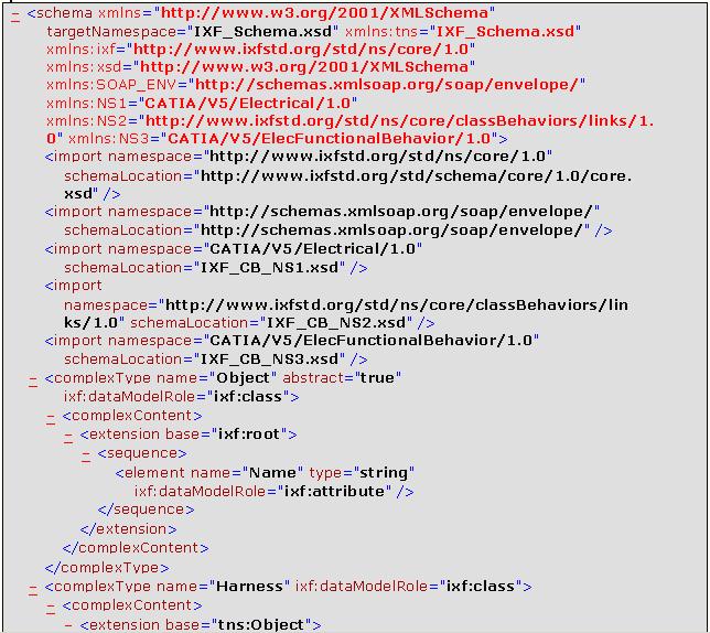

225 Page 225
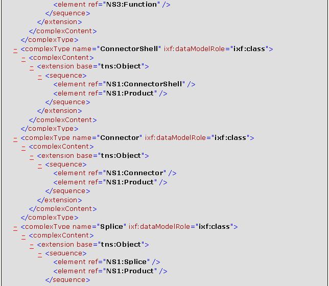
226 Page 226
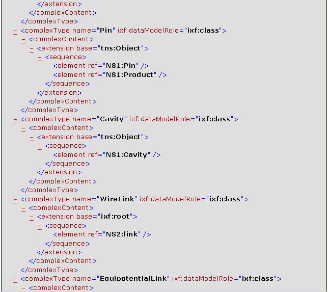
227 Page 227

228 Page 228 Electrical Behaviors
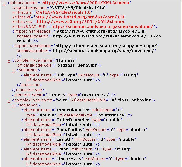
229 Page 229
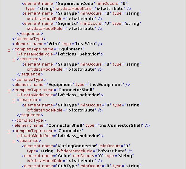
230 Page 230

231 Page 231 Link Type Behaviors

232 Page 232 Functional Behaviors
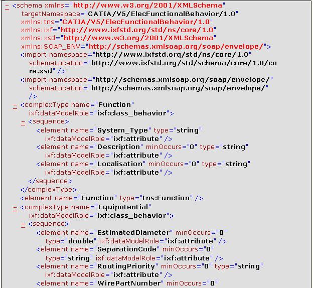

233 Page 233
Electrical Harness Installation
 Electrical Harness Installation Page 1 Overview Conventions What's New? Getting Started Entering the Workbench Setting Up the Options Creating a Bundle Segment Document Creating Construction Points Defining
Electrical 3D Design & Documentation
 Electrical 3D Design & Documentation Page 1 Overview Conventions User Tasks Using Electrical 3D Design & Documentation Entering the Electrical Assembly Design Workbench Entering the Electrical Part Design
Electrical Library Version 5 Release 13. Electrical Library
 Electrical Library Page 1 Overview Conventions What's New? Getting Started Entering the Electrical Part Design Workbench Defining a Single Insert Connector Defining a Cavity Connection Point Entering Electrical
Electrical Harness Flattening
 Electrical Harness Flattening Overview Conventions What's New? Getting Started Accessing the Electrical Harness Flattening Workbench Defining the Harness Flattening Parameters Extracting Data Flattening
DMU Space Engineering Assistant User Guide
 DMU Space Engineering Assistant User Guide Overview Conventions What's New? Getting Started User Tasks Setting Up Your Session Running an Interference Analysis Workbench Description DMU Space Engineering
Electrical System Functional Definition
 Electrical System Functional Definition Overview Conventions What's New? Getting Started Creating a New System Creating Equipment Creating Connectors Creating a Signal Connecting Saving Your System User
DMU Space Engineering Assistant User Guide
 Page 1 DMU Space Engineering Assistant User Guide Overview Conventions What's New? Getting Started User Tasks Setting Up Your Session Running a Interference Workbench Description DMU Space Engineering
Equipment Support Structures
 Equipment Support Structures Overview Conventions What's New? Getting Started Setting Up Your Session Creating a Simple Structural Frame Creating Non-uniform Columns Creating Plates with Openings Bracing
Electrical System Functional Definition
 Electrical System Functional Definition Preface What's New? Getting Started Basic Tasks Advanced Tasks Workbench Description Customizing Glossary Index Dassault Systèmes 1994-2000. All rights reserved.
Product Structure Version 5 Release 13. Product Structure
 Product Structure Page 1 Site Map Preface Conventions What's New? Basic Tasks Entering the Product Structure Workbench Opening a CATProduct with a Progress Bar Selecting Products only Selecting Modes Inserting
Equipment Support Structures
 Page 1 Equipment Support Structures Preface Using This Guide Where to Find More Information Conventions What's New? Getting Started Setting Up Your Session Creating a Simple Structural Frame Creating Non-uniform
Fastening Review Overview Basic Tasks DMU Fastening Review Interoperability Workbench Description Customizing Index
 Fastening Review Overview Conventions Basic Tasks Displaying Joined Parts in a Balloon Running the Fastening Rules Analysis Reporting Creating Structural Reports Creating Flat Reports DMU Fastening Review
Circuit Board Design Version 5 Release 13. Circuit Board Design
 Circuit Board Design Page 1 Overview Conventions What's New? Getting Started Accessing the Circuit Board Workbench Creating a Board Pocket and Holes Constraint Area Exporting Data Importing Data User Tasks
Tolerance Analysis of Deformable Assembly
 Tolerance Analysis of Deformable Assembly Overview Conventions What's New? Getting Started Entering the Workbench Creating a New Analysis Importing the Assembly Definition Computing a Tolerance Analysis
Structure Preliminary Layout
 Structure Preliminary Layout Overview Conventions What's New? Getting Started Setting Up Your Session Defining the Hull Form Setting Up Your Grid Creating Molded Forms Creating a Compartment Creating Boundaries
DMU Engineering Analysis Review
 DMU Engineering Analysis Review Overview Conventions What's New? Getting Started Entering DMU Engineering Analysis Review Workbench Generating an Image Visualizing Extrema Generating a Basic Analysis Report
DMU Engineering Analysis Review
 Page 1 DMU Engineering Analysis Review Preface Using This Guide Where to Find More Information Conventions What's New? Getting Started Inserting a CATAnalysis Document Using DMU Space Analysis From CATAnalysis
Knowledge Expert Overview What's New? Getting Started Basic Tasks Advanced Tasks Reference
 Knowledge Expert Overview Conventions What's New? Getting Started Creating an Expert Check Creating an Expert Rule Basic Tasks About RuleBases Storing a Rule Base in a Catalog Using a Rule Base Stored
Prismatic Machining Overview What's New Getting Started User Tasks
 Prismatic Machining Overview Conventions What's New Getting Started Enter the Workbench Create a Pocketing Operation Replay the Toolpath Create a Profile Contouring Operation Create a Drilling Operation
NC Manufacturing Verification
 NC Manufacturing Verification Overview Conventions What's New? User Tasks Accessing NC Manufacturing Verification Comparing the Machined Stock Part and the Design Part Pick Point Analysis in Video Mode
DMU Space Analysis Version 5 Release 13. DMU Space Analysis
 Page 1 DMU Space Analysis Preface Using This Guide More Information Conventions What's New? Getting Started Setting Up Your Session Measuring Minimum Distances Sectioning Detecting Clashes Measuring Between
DMU Optimizer Overview What's New? Getting Started User Tasks
 DMU Optimizer Overview Conventions What's New? Getting Started Starting a Session Generating a Silhouette Generating a Wrapping Generating a Thickness Generating an Offset Generating a Free Space User
Structure Preliminary Layout
 Page 1 Structure Preliminary Layout Preface Using This Guide Where to Find More Information What's New? Getting Started Setting Up Your Session Defining the Hull Form Setting Up Your Grid Creating Molded
Equipment & Systems Engineering. CATIA - Electrical Library 2 (ELB) CATIA V5R20
 CATIA V5R20") Equipment & Systems Engineering CATIA - Electrical Library 2 (ELB) CATIA V5R20 Equipment & Systems Engineering CATIA - Electrical Library Create and manage catalogs containing electrical components, and
Equipment & Systems Engineering CATIA - Electrical Library 2 (ELB) CATIA V5R20 Equipment & Systems Engineering CATIA - Electrical Library Create and manage catalogs containing electrical components, and
Compartment and Access
 Compartment and Access Preface Using This Guide What's New? Getting Started Entering the Workbench Set Correct Working Units and Grid Saving Documents User Tasks Creating/Modifying Wall Systems Building
NC Manufacturing Verification
 NC Manufacturing Verification Page 1 Preface Using This Guide Where to Find More Information Conventions What's New? User Tasks Accessing NC Manufacturing Verification Comparing the Machined Stock Part
Compartment and Access
 Compartment and Access Page 1 Preface Using This Guide What's New? Getting Started Entering the Workbench Set Correct Working Units and Grid Saving Documents User Tasks Creating/Modifying Wall Systems
Piping & Instrumentation Diagrams
 Piping & Instrumentation Diagrams Preface Using This Guide What's New? Getting Started Entering the Workbench Setting up Working Units and Grid Placing Components Routing a Piping Line or I & C Loop Placing
Advanced Meshing Tools
 Page 1 Advanced Meshing Tools Preface Using This Guide More Information Conventions What's New? Getting Started Entering the Advanced Meshing Tools Workbench Defining the Surface Mesh Parameters Setting
HVAC Diagrams Preface What's New? Getting Started User Tasks
 HVAC Diagrams Preface Using This Guide What's New? Getting Started Entering the Workbench Setting up Working Units and Grid Placing Components Routing an HVAC Line Placing Components in a Line Repositioning
Knowledge Expert Version 5 Release 13. Knowledge Expert
 Knowledge Expert Page 1 Preface Using this Guide What's New? Getting Started Basic Tasks About RuleBases Storing a Rule Base in a Catalog Using a Rule Base Stored in a Catalog Importing a Rule Base Activating
Aerospace Sheetmetal Design
 Aerospace Sheetmetal Design Page 1 Overview Conventions What's New? Getting Started Entering the Aerospace SheetMetal Design Workbench Defining the Aerospace SheetMetal Parameters Creating a Web from a
Electrical Cableway Routing
 Electrical Cableway Routing Preface Using This Guide What's New? Getting Started Entering the Workbench Placing a Hanger Routing a Loft Through Hangers Placing a Conduit on a Run Saving Documents Updating
Piping Design. Site Map Preface Getting Started Basic Tasks Advanced Tasks Customizing Workbench Description Index
 Piping Design Site Map Preface Getting Started Basic Tasks Advanced Tasks Customizing Workbench Description Index Dassault Systèmes 1994-2001. All rights reserved. Site Map Piping Design member member
Piping & Instrumentation Diagrams
 Page 1 Piping & Instrumentation Diagrams Preface Using This Guide What's New? Getting Started Entering the Workbench Setting up Working Units and Grid Placing Components Routing a Piping Line or I & C
Systems Space Reservation
 Systems Space Reservation Preface Using This Guide What's New? Getting Started Enter the Workbench Create an Equipment Reservation Set Correct Working Units and Grid Changing the Current Axis Saving Documents
Knowledge Advisor Overview What's New? Getting Started User Tasks
 Knowledge Advisor Overview Conventions What's New? Getting Started Using Parameters Using Formulas Using Rules Using Checks User Tasks Working with Parameters Creating a Parameter Introducing Parameters
DMU Fitting Simulator
 Page 1 DMU Fitting Simulator Preface Using This Guide More Information Conventions What's New? Getting Started Using Tracks Starting a Session Recording a Track Using Automatic Path Finder Using the Smooth
Getting Started Creating Cable and Harness Designs
 Chapter Getting Started Creating Cable and Harness Designs 1 In this chapter, you learn about Autodesk Inventor Cable and Harness functionality and the basic workflow to create and document a design. Objectives
Human Posture Analysis
 Human Posture Analysis Overview Conventions What's New? Getting Started Creating a Manikin User Tasks Using the Posture Editor Selecting or Editing the DOF (Degree of Freedom) Displaying and Editing Angular
Getting Started Creating Cable and Harness DesignsChapter1:
 Chapter 1 Getting Started Creating Cable and Harness DesignsChapter1: In this chapter, you learn about Autodesk Inventor Professional Cable and Harness functionality and the basic workflow to create and
MULTICAx PD Plug-in Overview What's New? User Tasks Customizing Glossary Index
 MULTICAx PD Plug-in Overview What's New? User Tasks Requirements Methodologies and Advice Initializing the Environment Initializing the Environment for Indirect Mode Initializing the Environment for Direct
FreeStyle Shaper Optimizer & Profiler
 FreeStyle Shaper Optimizer & Profiler Page 1 Preface Using This Guide More Information What's New? Getting Started Starting the FreeStyle Workbench Creating a First Surface Editing the Surface Creating
Learning the Pro/ENGINEER Interface
 2 Learning the Pro/ENGINEER Interface This chapter introduces the Pro/ENGINEER interface tools: the menus, the dashboards, the selection tools and the viewing controls. As you go through this chapter,
COPYRIGHTED MATERIAL. Making Excel More Efficient
 Making Excel More Efficient If you find yourself spending a major part of your day working with Excel, you can make those chores go faster and so make your overall work life more productive by making Excel
SheetMetal Design Version 5 Release 13. SheetMetal Design
 SheetMetal Design Page 1 Overview Conventions What's New? Getting Started Entering the Workbench Defining the Parameters Creating the First Wall Creating the Side Walls Creating a Cutout Creating Automatic
Preface. Version 5 Release 5. Mold Tooling Design
 Version 5 Release 5 Mold Tooling Design Preface Getting Started Basic Tasks Advanced Tasks Customization Workbench Description Glossary Index Preface The CATIA Version 5 Mold Tooling Design application
MULTICAx UD Plug-in Overview What's New? User Tasks Customizing Glossary Index
 MULTICAx UD Plug-in Overview What's New? User Tasks Requirements Methodologies and Advice Initializing the Environment Initializing the Environment for Indirect Mode Initializing the Environment for Direct
CATIA Teamcenter Interface RII
 CATIA Teamcenter Interface RII CMI RII Release 3.1 User Manual Copyright 1999, 2011 T-Systems International GmbH. All rights reserved. Printed in Germany. Contact T-Systems International GmbH PDC PLM Fasanenweg
Teamcenter Mobility Product decisions, anywhere, anytime. Features. Siemens AG All Rights Reserved.
 Teamcenter Mobility Product decisions, anywhere, anytime Features Settings App settings are located in the ipad Settings application. Page 2 Settings Toggles in the Settings pane allow you to hide tabs
Product Engineering Optimizer
 Product Engineering Optimizer Overview Conventions What's New? Getting Started Basic Tasks Using the Optimize Function Defining an Optimization Getting Familiar with the Optimization Dialog Box The Problem
MULTICAx SE Plug-in Overview What's New? User Tasks Customizing Index
 MULTICAx SE Plug-in Overview What's New? User Tasks Requirements Methodologies and Advice Initializing the Environment Importing Data Importing Part Files Interactively 3d com Interoperability:Importing
Using the JSON Iterator
 Using the JSON Iterator This topic describes how to process a JSON document, which contains multiple records. A JSON document will be split into sub-documents using the JSON Iterator, and then each sub-document
Tyler Dashboard. User Guide Version 5.8. For more information, visit
 Tyler Dashboard User Guide Version 5.8 For more information, visit www.tylertech.com. TABLE OF CONTENTS Tyler Dashboard... 4 Tyler Dashboard Features... 4 Tyler Dashboard Ribbon... 4 User Views... 5 Tools...
Human Posture Analysis
 Human Posture Analysis Page 1 Preface Using This Guide Where to Find More Information Conventions What's New? Getting Started Creating a Manikin User Tasks Using the Posture Editor Segments Degree of Freedom
Tutorial 3: Using the Waveform Viewer Introduces the basics of using the waveform viewer. Read Tutorial SIMPLIS Tutorials SIMPLIS provide a range of t
 Tutorials Introductory Tutorials These tutorials are designed to give new users a basic understanding of how to use SIMetrix and SIMetrix/SIMPLIS. Tutorial 1: Getting Started Guides you through getting
Quick Start Guide. ARIS Architect. Version 9.8 Service Release 2
 ARIS Architect Version 9.8 Service Release 2 October 2015 This document applies to ARIS Version 9.8 and to all subsequent releases. Specifications contained herein are subject to change and these changes
Shape Sculptor Version 5 Release 13. Shape Sculptor
 Shape Sculptor Page 1 Overview Using This Guide Where to Find More Information What's New? Getting Started Entering the Workbench Importing a Polygonal Mesh Decimating a Polygonal Mesh User Tasks Input
CATIA Teamcenter Interface RII
 CATIA Teamcenter Interface RII CMI RII Release 2.2 User Manual Copyright 1999, 2010 T-Systems International GmbH. All rights reserved. Printed in Germany. Contact T-Systems International GmbH Solution
Publication Number spse01695
 XpresRoute (tubing) Publication Number spse01695 XpresRoute (tubing) Publication Number spse01695 Proprietary and restricted rights notice This software and related documentation are proprietary to Siemens
Real Time Rendering Version 5 Release 13. Real Time Rendering
 Real Time Rendering Page 1 Preface Using This Guide Where to Find More Information Conventions What's New? Getting Started Applying Materials Modifying Mapped Material Basic Tasks Materials Applying a
Getting Started. The main tasks described in this section are the following:
 Getting Started Getting Started Before getting into the detailed instructions for using Interactive Drafting workbench, the following tutorial aims at giving you a feel of what you can do with the product.
MULTICAx STEP Plug-in
 MULTICAx STEP Plug-in Overview What's New User Tasks Requirements Methodologies and Advice Initializing the Environment Importing STEP Data Importing Part Files Interactively Translating Files from the
SolidWorks Implementation Guides. User Interface
 SolidWorks Implementation Guides User Interface Since most 2D CAD and SolidWorks are applications in the Microsoft Windows environment, tool buttons, toolbars, and the general appearance of the windows
Altiris IT Management Suite 7.1 from Symantec Enhanced Console Views Getting Started Guide. Version 7.1
 Altiris IT Management Suite 7.1 from Symantec Enhanced Console Views Getting Started Guide Version 7.1 Contents Section 1 Chapter 1 Altiris IT Management Suite 7.1 from Symantec Enhanced Console Views
BackupVault Desktop & Laptop Edition. USER MANUAL For Microsoft Windows
 BackupVault Desktop & Laptop Edition USER MANUAL For Microsoft Windows Copyright Notice & Proprietary Information Blueraq Networks Ltd, 2017. All rights reserved. Trademarks - Microsoft, Windows, Microsoft
FreeStyle Shaper & Optimizer
 FreeStyle Shaper & Optimizer Preface What's New Getting Started Basic Tasks Advanced Tasks Workbench Description Customizing Glossary Index Dassault Systèmes 1994-99. All rights reserved. Preface CATIA
Schematics in ArcMap Tutorial
 Schematics in ArcMap Tutorial Copyright 1995-2010 Esri All rights reserved. Table of Contents Introducing Schematics in ArcMap Tutorial........................ 3 Exercise 1: Getting familiar with Schematics
Specification Manager
 Enterprise Architect User Guide Series Specification Manager Author: Sparx Systems Date: 30/06/2017 Version: 1.0 CREATED WITH Table of Contents The Specification Manager 3 Specification Manager - Overview
ARIS Architect QUICK START GUIDE. Version Service Release 7
 ARIS Architect QUICK START GUIDE Version 9.8 - Service Release 7 December 2016 This document applies to ARIS Version 9.8 and to all subsequent releases. Specifications contained herein are subject to change
Teamcenter 11.1 Systems Engineering and Requirements Management
 SIEMENS Teamcenter 11.1 Systems Engineering and Requirements Management Systems Architect/ Requirements Management Project Administrator's Manual REQ00002 U REQ00002 U Project Administrator's Manual 3
Creating electrical designs
 Creating electrical designs 27.09.2018-34 TABLE OF CONTENTS Table of contents... 2 Introduction... 4 What you learn with this content... 5 Starting G-Electrical... 6 Interface... 6 Drawing area (1)...
Photo Studio. Preface What`s New? Getting Started Basic Tasks Advanced Tasks Workbench Description Customizing Glossary Index
 Photo Studio Preface What`s New? Getting Started Basic Tasks Advanced Tasks Workbench Description Customizing Glossary Index Dassault Systèmes 1994-2000. All rights reserved. Preface Welcome to Version
Publication Number spse01695
 XpresRoute (tubing) Publication Number spse01695 XpresRoute (tubing) Publication Number spse01695 Proprietary and restricted rights notice This software and related documentation are proprietary to Siemens
User Guide. Product: GreenFolders. Version: 3.8
 User Guide Product: GreenFolders Version: 3.8 Release Date: October 2014 GreenFolders 3.8 User Guide Introduction Table of Contents 1 Introduction... 6 2 General Information... 7 2.1 Login Procedure...
Server Edition USER MANUAL. For Microsoft Windows
 Server Edition USER MANUAL For Microsoft Windows Copyright Notice & Proprietary Information Redstor Limited, 2016. All rights reserved. Trademarks - Microsoft, Windows, Microsoft Windows, Microsoft Windows
MULTICAx ID Plug-in Overview What's New? User Tasks Customizing Glossary Index
 MULTICAx ID Plug-in Overview What's New? User Tasks Requirements Methodologies and Advice Initializing the Initializing the for Indirect Mode Initializing the for Direct Mode with 3d com Importing IDEAS
Structure Design Administration
 CATIA V5 Training Exercises Structure Design Administration Version 5 Release 19 January 2009 EDU_CAT_EN_SRA_AX_V5R19 1 Table of Contents Step 1: Creating a New Project 3 Do It Yourself 4 Step 2: Adding
WinSCP. Author A.Kishore/Sachin
 WinSCP WinSCP is a freeware windows client for the SCP (secure copy protocol), a way to transfer files across the network using the ssh (secure shell) encrypted protocol. It replaces other FTP programs
Enterprise Architect. User Guide Series. Tutorial. Author: Sparx Systems. Date: 26/07/2018. Version: 1.0 CREATED WITH
 Enterprise Architect User Guide Series Tutorial Author: Sparx Systems Date: 26/07/2018 Version: 1.0 CREATED WITH Table of Contents Tutorial 3 Startup 4 Create a Project 5 Add a View to your Model 6 Add
USING THE TRIBALL FOR POSITIONING
 USING THE TRIBALL FOR POSITIONING Although many important positioning tools are available, none are as versatile as the TriBall tool. This TriBall tool offers complete repositioning of many items: Shapes
Microsoft Access II 1.) Opening a Saved Database Music Click the Options Enable this Content Click OK. *
 Opening a Saved Database Music Click the Options Enable this Content Click OK. *") Microsoft Access II 1.) Opening a Saved Database Open the Music database saved on your computer s hard drive. *I added more songs and records to the Songs and Artist tables. Click the Options button next
Microsoft Access II 1.) Opening a Saved Database Open the Music database saved on your computer s hard drive. *I added more songs and records to the Songs and Artist tables. Click the Options button next
Server Edition. V8 Peregrine User Manual. for Microsoft Windows
 Server Edition V8 Peregrine User Manual for Microsoft Windows Copyright Notice and Proprietary Information All rights reserved. Attix5, 2015 Trademarks - Microsoft, Windows, Microsoft Windows, Microsoft
Enterprise Architect. User Guide Series. Tutorial
 Enterprise Architect User Guide Series Tutorial How do I build a model in Enterprise Architect? Follow this tutorial to build a simple model in a Firebird Repository, using Enterprise Architect. Author:
PPR Hub Principles Guide. Preface Basic Concepts Glossary Index. Dassault Systèmes All rights reserved.
 PPR Hub Principles Guide Preface Basic Concepts Glossary Index Dassault Systèmes 1994-2000. All rights reserved. Preface ENOVIA PPR (Product-Process-Resource) Hub is a rich object model that is tailored
CADEX CATIA CADAM DRAFTING
 CADEX CATIA CADAM DRAFTING o Electrical Schematic Capture - Quickly create and modify diagrams - Graphics plus built-in intelligence - Convert images to intelligent CADEX o Create and Manage Libraries
Author A.Kishore/Sachin WinSCP
 WinSCP WinSCP is a freeware windows client for the SCP (secure copy protocol), a way to transfer files across the network using the ssh (secure shell) encrypted protocol. It replaces other FTP programs
ICS Tutorials: Basic Operations
 ICS Tutorials: Basic Operations This tutorial introduces the basic components of Builder Xcessory. For more detailed information, see the Builder Xcessory Reference Manual. This book is directly accessible
Using the VMware vcenter Orchestrator Client. vrealize Orchestrator 5.5.1
 Using the VMware vcenter Orchestrator Client vrealize Orchestrator 5.5.1 You can find the most up-to-date technical documentation on the VMware website at: https://docs.vmware.com/ If you have comments
Desktop & Laptop Edition
 Desktop & Laptop Edition USER MANUAL For Mac OS X Copyright Notice & Proprietary Information Redstor Limited, 2016. All rights reserved. Trademarks - Mac, Leopard, Snow Leopard, Lion and Mountain Lion
NX electrical and mechanical routing
 electrical and mechanical routing Accelerating design of electrical and mechanical routed systems in complex assemblies Electrical routing benefits Re-uses logical design eliminates redundant data creation
CATIA Teamcenter Interface
 CATIA Teamcenter Interface CMI Release 10.11 User Manual Copyright 1999, 2018 T-Systems International GmbH. All rights reserved. Printed in Germany. Contact T-Systems International GmbH GDC Product Lifecycle
Quick Guide FAST HR. For more resources, including a guide on FAST HR codes, visit # Instructions Screenshot
 Tips & tricks This quick guide describes basic navigation within the FAST HR reporting tool, including how to use filter options, format columns and export reports. For more resources, including a guide
COMOS. Lifecycle 3D Integration Operation. COMOS PDMS Integration 1. Material management 2. COMOS 3D viewing 3. References 4.
 1 Material management 2 COMOS Lifecycle COMOS 3D viewing 3 References 4 Operating Manual 03/2017 V 10.2.1 A5E37098336-AB Legal information Warning notice system This manual contains notices you have to
PaperClip32. Revision 2.0
 PaperClip32 Quick Start Guide Revision 2.0 Copyright Information Copyright 2003, PaperClip Software, Inc. The PaperClip32 product name and PaperClip Logo are registered trademarks of PaperClip Software,
StarTeam File Compare/Merge StarTeam File Compare/Merge Help
 StarTeam File Compare/Merge 12.0 StarTeam File Compare/Merge Help Micro Focus 575 Anton Blvd., Suite 510 Costa Mesa, CA 92626 Copyright 2011 Micro Focus IP Development Limited. All Rights Reserved. Portions
[ Getting Started with Analyzer, Interactive Reports, and Dashboards ] ]
![[ Getting Started with Analyzer, Interactive Reports, and Dashboards ] ]](/thumbs/88/117545107.jpg "[ Getting Started with Analyzer, Interactive Reports, and Dashboards ] ]") Version 5.3 [ Getting Started with Analyzer, Interactive Reports, and Dashboards ] ] https://help.pentaho.com/draft_content/version_5.3 1/30 Copyright Page This document supports Pentaho Business Analytics
Version 5.3 [ Getting Started with Analyzer, Interactive Reports, and Dashboards ] ] https://help.pentaho.com/draft_content/version_5.3 1/30 Copyright Page This document supports Pentaho Business Analytics
SAP Engineering Control Center 5.1
 Application Help Document Version: 20.0 2018-06-22 CUSTOMER Typographical Conventions Format Example Description Words or characters that are quoted from the screen display. These include field names,
Overview of Cisco UCS Manager GUI
 Overview of Cisco UCS Manager GUI This chapter includes the following sections: Overview of Cisco UCS Manager GUI, page 1 Logging in to Cisco UCS Manager GUI through HTTPS, page 6 Logging in to Cisco UCS
Table of Contents. Revu ipad. v3.6. Navigation. Document Manager. File Access. Markups. Signature Tool. Field Verification Measurements
 Table of Contents Navigation Document Manager File Access Markups Signature Tool Field Verification Measurements Editing Properties Tool Sets & the Tool Chest Markups List Forms Studio Sessions Studio