Serial Peripheral Interface (SPI)
|
|
|
- Jeffery Lindsey
- 6 years ago
- Views:
Transcription
1 SPI and I 2 C 1
2 Serial Peripheral Interface (SPI) SPI allow half/full duplex, synchronous, serial communication with external devices The interface can be configured as master for MCU board Communication clock (SCLK) is also provided for synchronous communication 2
3 SPI features Full duplex synchronous transfer on 3 lines Simplex synchronous transfer on 2 lines Master or slave operation Multi-master mode support 3
4 SPI block diagram 4
5 Basic SPI configuration Usually, SPI is connected using 4 pins MISO (Master In/Slave Out): transmit data in slave mode, and received data in master mode MOSI (Master Out/Slave In): transmit data in master mode, and received data in slave mode SCLK: Clock NSS (slave select): to select a slave device 5
6 Single Master/Single Slave config 6
7 Configuring SPI in Master mode Select BR[2:0] to define baud rate Select CPOL and CPHA to define data transfer and serial clock relationship Set DFF bit to define 8 or 16 bit data transfer Configure LSBFirst bit in SPI_CR1 to define frame format Connect NSS if required MSTR and SPE must be set 7
8 Configuring SPI in Slave mode Select CPOL and CPHA to define data transfer and serial clock relationship Set DFF bit to define 8 or 16 bit data transfer LSBFirst bit in SPI_CR1 must be the same as Master Connect NSS if required Clear MSTR and set SPE bit 8
9 Timing diagram 9
10 Control register TXE bit is set on the transfer data from Tx buffer to the shift register RXNE bit is set on the data transfer from shift register to Rxbuffer 10
11 I2C Inter-Integrated bus (I2C) Interface between microcontroller and I2C bus Provide multi-master support 11
12 I2C feature Master master configuration I2C master feature Clock generation Start and Stop generation I2C slave feature programmable I2C address detection dual address capabilities Stop bit detection 2 interrupt vectors 12
13 I2C function There are 2 pins, data pin (SDA) and clock (SCL) It can be connected with standard speed (up to 100KHz) or fast mode (up to 400KHz) 13
14 I2C function description Mode selection: Slave transmit Slave receiver Master transmit Master receiver By default, it operates in Slave mode. It automatic switch once it receive a START condition from master to slave 14
15 Communication flow In master mode, I2C interface initiates the data transfer and the clock signal. A serial data transfer always begins with a start condition and ends with a stop condition In slave mode, the interface is capable of recognizing its own address (7-10 bits) Data are transmitted as 8 bit bytes, MSB first. A 9 th clock pulse, receiver must send an acknowledge 15
16 I2C data transfer 16
17 I2C block diagram 17
18 Mode selection By default, the device operates in slave mode. It will automatically switch from slave to master, after the device generate START condition from master to slave. 18
19 I2c master mode Program the peripheral input clock in I2C_CR2 register to generate correct timing Configure the clock control register Configure the rise time register Program I2C_CR1 register to enable the peripheral Set the start bit in I2C_CR1 to generate a Start condition 19

20 Transfer sequence 20
21 I2C reading data 1. Send start sequence 2. Send address of the device (with read bit) 3. Wait for response 4. Send address register of the device 5. Wait for response 6. Send start sequence again 7. Send address of the device (with read bit) 8. Wait for response 9. Wait for data (high byte first) Wait for data (lower byte)
22 I2C writing data 1. Send start sequence 2. Send address of the device (with write bit) 3. Wait for response 4. Send address register of the device 5. Wait for response 6. Write high byte 7. Write lower byte 22
23 Example: reading data from compass 1. Send start sequence 2. Send address 3. Send start sequence again 4. Send address again 5. Read data 6. Send stop sequence 23
24 Example int main(){ } RCC_setup(); GPIO_setup(); I2C_setup(); while(1){ } if(i2c_lm75_status()==success){ } temp = LM75_readTemp(); void GPIO_setup(){ GPIO_InitTypeDef GPIO_InitStructure; RCC_APB2PeriphClockCmd(RCC_APB2Periph_GPIOB RCC_APB2Periph_AFIO,ENABLE); GPIO_InitStructure.GPIO_Pin = GPIO_Pin_6 GPIO_Pin_7; GPIO_InitStructure.GPIO_Speed = GPIO_Speed_50MHz; GPIO_InitStructure.GPIO_Mode = GPIO_Mode_AF_OD; GPIO_Init(GPIOB, &GPIO_InitStructure); } 24
25 void I2C_setup(){ I2C_InitTypeDef I2C_InitStructure; RCC_APB1PeriphClockCmd(RCC_APB1Periph_I2C1,ENABLE); I2C_DeInit(I2C1); I2C_InitStructure.I2C_Mode = I2C_Mode_I2C; I2C_InitStructure.I2C_DutyCycle = I2C_DutyCycle_2; I2C_InitStructure.I2C_OwnAddress1 = 0x00; I2C_InitStructure.I2C_Ack = I2C_Ack_Enable; I2C_InitStructure.I2C_AcknowledgedAddress = I2C_AcknowledgeAddress_7bit; I2C_InitStructure.I2C_ClockSpeed = ; I2C_Init(I2C1, &I2C_InitStructure); I2C_Cmd(I2C1, ENALBE); // enable I2C1 } 25
26 ErrorStatus I2C_LM75_Status(){ unsigned int I2C_TimeOut = ; I2C_ClearFlag(I2C1, I2C_FLAG_AF); I2C_AcknowledgeConfig(I2C1, ENABLE); I2C_GenrateSTART(I2C1, ENABLE); while(!i2c_checkevent(i2c1, I2C_EVENT_MASTER_MODE_SELECT); // wait for start I2C_Send7BitAddress(I2C1, LM75_ADDR, I2C_Direction_Transmitter); //send slave addr while(!i2c_checkevent(i2c1,i2c_event_master_transmitter_mode_selecte D)) && I2C_TimeOut){ // get status ready } } I2C_TimeOut--; if(i2c_getflagstatus(i2c1,i2c_flag_af!= 0x0){ return ERROR; }else return SUCCESS; unsigned int LM75_readTemp(){ unsigned int RegValue = 0; I2C_AcknowledgeConfig(I2C1, ENABLE); I2C_GenerateStart(I2C1, ENABLE); // wait for START to complete while(i2c_checkevent(i2c1, I2CEVENT_MASTER_MODE_SELECT)); I2C_Send7bitAddress(I2C1, LM75_ADDR, I2C_Direction_Transmitter); 26
27 // wait for data transfer complete while(i2c_checkevent(i2c1, I2CEVENT_MASTER_RECEIVER_MODE_SELECTED)); // send data pointer I2C_SendData(I2C1,LM75_TEMP_REG); // wait for data transfer complete while(i2c_checkevent(i2c1, I2CEVENT_MASTER_BYTE_TRANSMITTED)); I2C_GenerateStart(I2C1, ENABLE); // wait for START to complete while(i2c_checkevent(i2c1, I2CEVENT_MASTER_MODE_SELECT)); I2C_Send7bitAddress(I2C1, LM75_ADDR, I2C_Direction_Receiver); while(i2c_checkevent(i2c1, I2CEVENT_MASTER_RECEIVER_MODE_SELECTED)); while(i2c_checkevent(i2c1, I2CEVENT_MASTER_BYTE_RECEIVED)); // store data RegValue = I2C_ReceiveData(I2c1) << 8; // disable acknowledgement I2CAcknowledgeConfig(I2C1, DISABLE); // send I2C1 stop condition I2c_GenerateStop(I2C1, ENABLE); // test on EV7 and clear while(i2c_checkevent(i2c1, I2CEVENT_MASTER_BYTE_RECEIVED)); Regvalue!= I2C_ReceiveData(I2C1); return RegValue >> 7; 27 }
28 Simulink SPI Master Setup 28
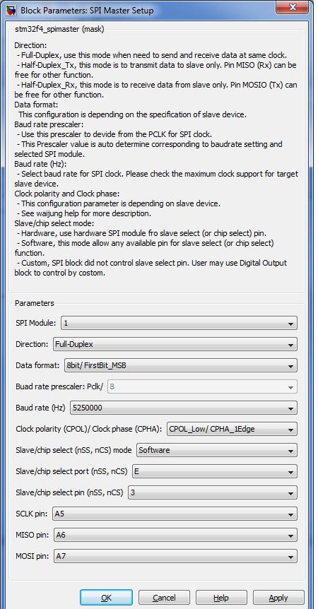
29 Configuration 29
30 SPI Read/Write 30

31 Configuration Data Read/Write = the number of port 31
")
32 Clock polarity and clock phase Clock polarity low and clock phase 1 st edge (CPOL_Low/CPHA_1Edge) 32
 33")
33 Clock polarity and clock phase Clock polarity low and clock phase 2nd edge (CPOL_Low/CPHA_2Edge) 33
")
34 Clock polarity and clock phase Clock polarity high and clock phase 1 st edge (CPOL_High/CPHA_1Edge) 34

 35")
35 Clock polarity and clock phase Clock polarity high and clock phase 2nd edge (CPOL_High/CPHA_2Edge) 35

36 SPI Example 36
37 SPI Example 37
38 SPI Subsystem 38

39 Hardware 39

40 Test with Matlab Host 40
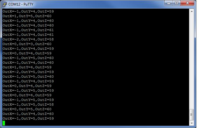
41 Output 41
42 I2C 42
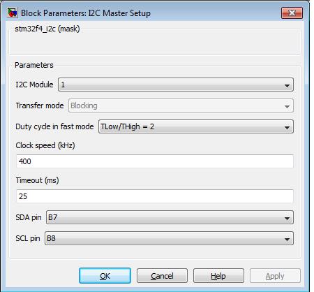
43 Configuration 43
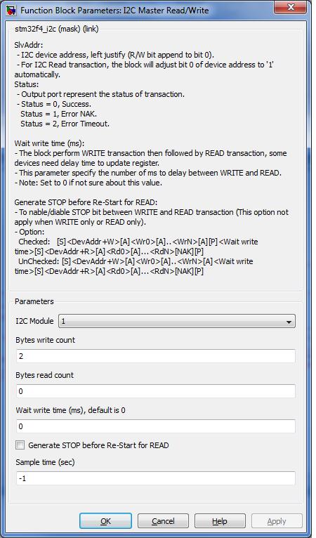
44 I2C Read/Write 44
45 I2C Configuration 45

46 I2C Sensor L3G4200D 46

47 Hardware 47

48 Matlab Host 48
49 Output 49

50 Humidity and Temperature Sensor 50

51 Hardware 51
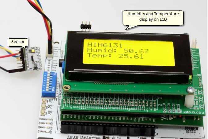
52 Output 52
53 Questions? 53
17. Serial communication - I 2 C
 7. Serial communication - I 2 C Two typical serial busses will be discussed and their use will be demonstrated in this and next chapter, these are I 2 C (Inter Integrated Circuit, IIC or I2C) and SPI (Serial
OUTLINE. SPI Theory SPI Implementation STM32F0 SPI Resources System Overview Registers SPI Application Initialization Interface Examples
 SERIAL PERIPHERAL INTERFACE (SPI) George E Hadley, Timothy Rogers, and David G Meyer 2018, Images Property of their Respective Owners OUTLINE SPI Theory SPI Implementation STM32F0 SPI Resources System
The 9S12 Serial Peripheral Inteface (SPI) Huang Section 10.2 through 10.6 SPI Block User Guide
 Huang Section 10.2 through 10.6 SPI Block User Guide") The 9S12 Serial Peripheral Inteface (SPI) Huang Section 102 through 106 SPI Block User Guide The 9S12 Serial Peripheral Interface (SPI) The 9S12 has a Synchronous Serial Interface On the 9S12 it is called
The 9S12 Serial Peripheral Inteface (SPI) Huang Section 102 through 106 SPI Block User Guide The 9S12 Serial Peripheral Interface (SPI) The 9S12 has a Synchronous Serial Interface On the 9S12 it is called
MEMS Differential pressure Sensor D6F-PH. User s Manual. MEMS Differential pressure Sensor A288-E1-01
 MEMS Differential pressure Sensor D6F-PH User s Manual MEMS Differential pressure Sensor A288-E1-01 Contents 1. Outline...2 2. Structure...2 3. Dimensions...2 4. Principle of Pressure detection...3 5.
LABORATORIO DI ARCHITETTURE E PROGRAMMAZIONE DEI SISTEMI ELETTRONICI INDUSTRIALI. Laboratory Lesson 9: Serial Peripheral Interface (SPI)
") LABORATORIO DI ARCHITETTURE E PROGRAMMAZIONE DEI SISTEMI ELETTRONICI INDUSTRIALI Laboratory Lesson 9: Serial Peripheral Interface (SPI) Prof. Luca Benini Prof Davide Rossi
LABORATORIO DI ARCHITETTURE E PROGRAMMAZIONE DEI SISTEMI ELETTRONICI INDUSTRIALI Laboratory Lesson 9: Serial Peripheral Interface (SPI) Prof. Luca Benini Prof Davide Rossi
spi 1 Fri Oct 13 13:04:
 spi 1 Fri Oct 1 1:: 1.1 Introduction SECTION SERIAL PERIPHERAL INTERFACE (SPI) The SPI module allows full-duplex, synchronous, serial communication with peripheral devices.. Features Features of the SPI
EE 456 Fall, Table 1 SPI bus signals. Figure 1 SPI Bus exchange of information between a master and a slave.
 EE 456 Fall, 2009 Notes on SPI Bus Blandford/Mitchell The Serial Peripheral Interface (SPI) bus was created by Motorola and has become a defacto standard on many microcontrollers. This is a four wire bus
Raspberry Pi - I/O Interfaces
 ECE 1160/2160 Embedded Systems Design Raspberry Pi - I/O Interfaces Wei Gao ECE 1160/2160 Embedded Systems Design 1 I/O Interfaces Parallel I/O and Serial I/O Parallel I/O: multiple input/output simultaneously
McMaster University Embedded Systems. Computer Engineering 4DS4 Lecture 6 Serial Peripherals Amin Vali Feb. 2016
 McMaster University Embedded Systems Computer Engineering 4DS4 Lecture 6 Serial Peripherals Amin Vali Feb. 2016 Serial Peripherals I2C Inter-IC Bus X/Y Coord. RGB data LCD config controller LCD data controller
For reference only Refer to the latest documents for details
 STM32F3 Technical Training For reference only Refer to the latest documents for details Serial peripheral interface SPI 3 SPI Features (1/2) 3 Full duplex synchronous transfers (3 lines) Half duplex/simplex
Parallel Data Transfer. Suppose you need to transfer data from one HCS12 to another. How can you do this?
 Introduction the Serial Communications Huang Sections 9.2, 10.2, 11.2 SCI Block User Guide SPI Block User Guide IIC Block User Guide o Parallel vs Serial Communication o Synchronous and Asynchronous Serial
Module 3.C. Serial Peripheral Interface (SPI) Tim Rogers 2017
 Tim Rogers 2017") Module 3.C Serial Peripheral Interface (SPI) Tim Rogers 2017 Learning Outcome #3 An ability to effectively utilize the wide variety of peripherals integrated into a contemporary microcontroller How? A:
Module 3.C Serial Peripheral Interface (SPI) Tim Rogers 2017 Learning Outcome #3 An ability to effectively utilize the wide variety of peripherals integrated into a contemporary microcontroller How? A:
Serial Peripheral Interface. What is it? Basic SPI. Capabilities. Protocol. Pros and Cons. Uses
 Serial Peripheral Interface What is it? Basic SPI Capabilities Protocol Serial Peripheral Interface http://upload.wikimedia.org/wikipedia/commons/thumb/e/ed/ SPI_single_slave.svg/350px-SPI_single_slave.svg.png
Embedded Systems and Software. Serial Interconnect Buses I 2 C (SMB) and SPI
 and SPI") Embedded Systems and Software Serial Interconnect Buses I 2 C (SMB) and SPI I2C, SPI, etc. Slide 1 Provide low-cost i.e., low wire/pin count connection between IC devices There are many of serial bus standards
Embedded Systems and Software Serial Interconnect Buses I 2 C (SMB) and SPI I2C, SPI, etc. Slide 1 Provide low-cost i.e., low wire/pin count connection between IC devices There are many of serial bus standards
Introduction to I2C & SPI. Chapter 22
 Introduction to I2C & SPI Chapter 22 Issues with Asynch. Communication Protocols Asynchronous Communications Devices must agree ahead of time on a data rate The two devices must also have clocks that are
I2C ( EEPROM-AT24C02 )
") I2C ( EEPROM-AT24C02 ) E-Mail fire firestm32@foxmail.com QQ 313303034 firestm32.blog.chinaunix.net STM32 ST3.0.0 EERPOM PB6-I2C1_SCL PB7-I2C1_SDA startup/start_stm32f10x_hd.c CMSIS/core_cm3.c CMSIS/system_stm32f10x.c
I2C ( EEPROM-AT24C02 ) E-Mail fire firestm32@foxmail.com QQ 313303034 firestm32.blog.chinaunix.net STM32 ST3.0.0 EERPOM PB6-I2C1_SCL PB7-I2C1_SDA startup/start_stm32f10x_hd.c CMSIS/core_cm3.c CMSIS/system_stm32f10x.c
Microcontrollers and Interfacing
 Microcontrollers and Interfacing Week 10 Serial communication with devices: Serial Peripheral Interconnect (SPI) and Inter-Integrated Circuit (I 2 C) protocols College of Information Science and Engineering
General Purpose Input/Output (GPIO)
") GPIO 1 General Purpose Input/Output (GPIO) Sometimes it is called bus expander GPIO is an interface available on microcontrollers/microprocessors It can act as input or output GPIO often are arranged into
GPIO 1 General Purpose Input/Output (GPIO) Sometimes it is called bus expander GPIO is an interface available on microcontrollers/microprocessors It can act as input or output GPIO often are arranged into
Serial Peripheral Interface (SPI)
") SPI = Simple, 3 wire, full duplex, synchronous serial data transfer Interfaces to many devices, even many non-spi peripherals Can be a master or slave interface 4 interface pins: -MOSI master out slave
SPI = Simple, 3 wire, full duplex, synchronous serial data transfer Interfaces to many devices, even many non-spi peripherals Can be a master or slave interface 4 interface pins: -MOSI master out slave
Design and development of embedded systems for the Internet of Things (IoT) Fabio Angeletti Fabrizio Gattuso
 Fabio Angeletti Fabrizio Gattuso") Design and development of embedded systems for the Internet of Things (IoT) Fabio Angeletti Fabrizio Gattuso Microcontroller It is essentially a small computer on a chip Like any computer, it has memory,
Design and development of embedded systems for the Internet of Things (IoT) Fabio Angeletti Fabrizio Gattuso Microcontroller It is essentially a small computer on a chip Like any computer, it has memory,
Introduction the Serial Communications Parallel Communications Parallel Communications with Handshaking Serial Communications
 Introduction the Serial Communications Parallel Communications Parallel Communications with Handshaking Serial Communications o Asynchronous Serial (SCI, RS-232) o Synchronous Serial (SPI, IIC) The MC9S12
Learn how to communicate
 USART 1 Learn how to communicate Programmed I/O (Software Polling) Interrupt Driven I/O Direct Memory Access (DMA) 2 Programmed I/O (Polling) Processor must read and check I/O ready bits for proper value
More on the 9S12 SPI Using the Dallas Semiconductor DS1302 Real Time Clock with the 9S12 SPI
 More on the 9S12 SPI Using the Dallas Semiconductor DS1302 Real Time Clock with the 9S12 SPI Using the 9S12 SPI The SPI has a data register (SPIDR) and a shift register. To write data to the SPI, you write
Interfacing Techniques in Embedded Systems
 Interfacing Techniques in Embedded Systems Hassan M. Bayram Training & Development Department training@uruktech.com www.uruktech.com Introduction Serial and Parallel Communication Serial Vs. Parallel Asynchronous
Using the Z8051 MCU s USI Peripheral as an SPI Interface
 Using the Z8051 MCU s USI Peripheral as an SPI Interface AN035901-0513 Abstract This document describes how to configure Zilog s Z8051 Universal Serial Interface (USI) peripheral to operate as Serial Peripheral
SPI 3-Wire Master (VHDL)
") SPI 3-Wire Master (VHDL) Code Download Features Introduction Background Port Descriptions Clocking Polarity and Phase Command and Data Widths Transactions Reset Conclusion Contact Code Download spi_3_wire_master.vhd
SPI 3-Wire Master (VHDL) Code Download Features Introduction Background Port Descriptions Clocking Polarity and Phase Command and Data Widths Transactions Reset Conclusion Contact Code Download spi_3_wire_master.vhd
EE 308 Spring Using the 9S12 SPI
 Using the 9S12 SPI The SPI has a data register (SPIDR) and a shift register. To write data to the SPI, you write to the SPIDR data register. The 9S12 automatically transfers the data to the shift register
Menu. What is SPI? EEL 3744 EEL 3744 SPI
 Menu Concepts >Problems in serial communications Timing Synchronization: How do you line up the bit boundaries? Message Synchronization: How do you line up messages? Look into my... >Synchronous data solves
LAB4. Program the on chip SPI module
 LAB4 Program the on chip SPI module Outline Learn to utilize the on-chip SPI module Implement it in C Translate it to ARM Assembly Test and verify the result using oscilloscope and shift register. Serial
The I2C BUS Interface
 The I 2 C BUS Interface ARSLAB - Autonomous and Robotic Systems Laboratory Dipartimento di Matematica e Informatica - Università di Catania, Italy santoro@dmi.unict.it L.S.M. 1 Course What is I 2 C? I
Introduction the Serial Communications Huang Sections 9.2, 10.2 SCI Block User Guide SPI Block User Guide
 Introduction the Serial Communications Huang Sections 9.2,.2 SCI Block User Guide SPI Block User Guide Parallel Data Transfer Suppose you need to transfer data from one HCS2 to another. How can you do
SPI( 2M-Flash-W25X16 )
") SPI( 2M-Flash-W25X16 ) E-Mail fire firestm32@foxmail.com QQ 313303034 firestm32.blog.chinaunix.net STM32 ST3.0.0 FLASH ID PA4-SPI1-NSS : W25X16-CS PA5-SPI1-SCK : W25X16-CLK PA6-SPI1-MISO : W25X16-DO PA7-SPI1-MOSI
SPI( 2M-Flash-W25X16 ) E-Mail fire firestm32@foxmail.com QQ 313303034 firestm32.blog.chinaunix.net STM32 ST3.0.0 FLASH ID PA4-SPI1-NSS : W25X16-CS PA5-SPI1-SCK : W25X16-CLK PA6-SPI1-MISO : W25X16-DO PA7-SPI1-MOSI
Serial Peripheral Interface (SPI)
") Serial Peripheral Interface (SPI) MSP432 SPI eusci = enhanced Universal Serial Communications Interface 2 tj MSP432 SPI ARM (AMBA Compliant) 7/8 bit transmission Master/Slave LSB/MSB first Separate RX/TX
Serial Peripheral Interface (SPI) MSP432 SPI eusci = enhanced Universal Serial Communications Interface 2 tj MSP432 SPI ARM (AMBA Compliant) 7/8 bit transmission Master/Slave LSB/MSB first Separate RX/TX
SPI Block User Guide V02.07
 DOCUMENT NUMBER S12SPIV2/D SPI Block User Guide V02.07 Original Release Date: 21 JAN 2000 Revised: 11 Dec 2002 Motorola, Inc. Motorola reserves the right to make changes without further notice to any products
Lecture 25 March 23, 2012 Introduction to Serial Communications
 Lecture 25 March 23, 2012 Introduction to Serial Communications Parallel Communications Parallel Communications with Handshaking Serial Communications Asynchronous Serial (e.g., SCI, RS-232) Synchronous
EE 308: Microcontrollers
 EE 308: Microcontrollers Serial Perpherial Interface (SPI) Aly El-Osery Electrical Engineering Department New Mexico Institute of Mining and Technology Socorro, New Mexico, USA April 9, 2018 Aly El-Osery
An SPI Temperature Sensor Interface with the Z8 Encore! SPI Bus
 Application Note An SPI Temperature Sensor Interface with the Z8 Encore! SPI Bus AN012703-0608 Abstract This Application Note provides an overview of Zilog s Z8 Encore! Serial Peripheral Interface (SPI)
ice40 UltraPlus I 2 C and SPI Hardened IP Usage Guide Radiant Software
 ice40 UltraPlus I 2 C and SPI Hardened IP Usage Guide Radiant Software FPGA-TN-02053-1.0 February 2018 Contents Acronyms in This Document... 4 1. Introduction... 5 2. I 2 C IP Core Overview... 6 2.1. Key
C8051F700 Serial Peripheral Interface (SPI) Overview
 Overview") C8051F700 Serial Peripheral Interface (SPI) Overview Agenda C8051F700 block diagram C8051F700 device features SPI operation overview SPI module overview Where to learn more 2 Introducing The C8051F700
C8051F700 Serial Peripheral Interface (SPI) Overview Agenda C8051F700 block diagram C8051F700 device features SPI operation overview SPI module overview Where to learn more 2 Introducing The C8051F700
< W3150A+ / W5100 Application Note for SPI >
 < W3150A+ / W5100 Application Note for SPI > Introduction This application note describes how to set up the SPI in W3150A+ or W5100. Both the W3150A+ and W5100 have same architecture. W5100 is operated
Serial Peripheral Interface (SPI) Host Controller Data Sheet
 Host Controller Data Sheet") Serial Peripheral Interface (SPI) Host Controller Data Sheet Proven System Block (PSB) for QuickLogic Customer Specific Standard Products (CSSPs) Features Supports Master configuration (Multi-Master configuration
Serial Peripheral Interface (SPI) Host Controller Data Sheet Proven System Block (PSB) for QuickLogic Customer Specific Standard Products (CSSPs) Features Supports Master configuration (Multi-Master configuration
Serial Peripheral Interface (SPI) Last updated 8/7/18
 Last updated 8/7/18") Serial Peripheral Interface (SPI) Last updated 8/7/18 MSP432 SPI eusci = enhanced Universal Serial Communications Interface 2 tj MSP432 SPI ARM (AMBA Compliant) 7/8 bit transmission Master/Slave LSB/MSB
Serial Peripheral Interface (SPI) Last updated 8/7/18 MSP432 SPI eusci = enhanced Universal Serial Communications Interface 2 tj MSP432 SPI ARM (AMBA Compliant) 7/8 bit transmission Master/Slave LSB/MSB
Universität Dortmund. IO and Peripheral Interfaces
 IO and Peripheral Interfaces Microcontroller System Architecture Each MCU (micro-controller unit) is characterized by: Microprocessor 8,16,32 bit architecture Usually simple in-order microarchitecture,
Lecture 14 Serial Peripheral Interface
 www.atomicrhubarb.com/systems Lecture 14 Serial Peripheral Interface Section Topic Where in the books Zilog PS220 "Enhanced Serial Peripheral Interface" Assorted datasheets Synchronous Serial Buses 1-wire
Mbed Microcontroller SPI. Spring, 2018 Prof. Jungkeun Park
 Mbed Microcontroller SPI Spring, 2018 Prof. Jungkeun Park SPI Logic Signals Full duplex mode using a master-slave architecture Single master Originates the frame for reading and writing https://en.wikipedia.org/wiki/serial_peripheral_interface_bus
IV B.Tech. I Sem (R13) ECE : Embedded Systems : UNIT -4 1 UNIT 4
 ECE : Embedded Systems : UNIT -4 1 UNIT 4") IV B.Tech. I Sem (R13) ECE : Embedded Systems : UNIT -4 1 UNIT 4 4.1. Serial data communication basics ----------- 1 4.2. UART ------------------------------------------------ 4 4.3. Serial Peripheral
IV B.Tech. I Sem (R13) ECE : Embedded Systems : UNIT -4 1 UNIT 4 4.1. Serial data communication basics ----------- 1 4.2. UART ------------------------------------------------ 4 4.3. Serial Peripheral
An SPI interface for the 65(C)02 family of microprocessors
02 family of microprocessors") Rev 4/B Dec 30, 2011 65SPI/B An SPI interface for the 65(C)02 family of microprocessors This device was created to provide a basic SPI interface for the 65xx family of microprocessors. Currently, the only
Rev 4/B Dec 30, 2011 65SPI/B An SPI interface for the 65(C)02 family of microprocessors This device was created to provide a basic SPI interface for the 65xx family of microprocessors. Currently, the only
i_csn i_wr i_rd i_cpol i_cpha i_lsb_first i_data [15:0] o_data [15:0] o_tx_ready o_rx_ready o_rx_error o_tx_error o_tx_ack o_tx_no_ack
![i_csn i_wr i_rd i_cpol i_cpha i_lsb_first i_data [15:0] o_data [15:0] o_tx_ready o_rx_ready o_rx_error o_tx_error o_tx_ack o_tx_no_ack](/thumbs/74/71193571.jpg "i_csn i_wr i_rd i_cpol i_cpha i_lsb_first i_data [15:0] o_data [15:0] o_tx_ready o_rx_ready o_rx_error o_tx_error o_tx_ack o_tx_no_ack") October 2012 Introduction Reference Design RD1142 The Serial Peripheral Interface (SPI) is used primarily for synchronous serial communication between a host processor and its peripherals. The SPI bus
October 2012 Introduction Reference Design RD1142 The Serial Peripheral Interface (SPI) is used primarily for synchronous serial communication between a host processor and its peripherals. The SPI bus
17. I 2 C communication channel
 17. I 2 C communication channel Sometimes sensors are distant to the microcontroller. In such case it might be impractical to send analog signal from the sensor to the ADC included in the microcontroller
Understanding SPI with Precision Data Converters
 Understanding SPI with Precision Data Converters By: Tony Calabria Presented by: 1 Communication Comparison SPI - Serial Peripheral Interface Bus I2C - Inter- Integrated Circuit Parallel Bus Advantages
SPI: Serial Peripheral Interface
 ECE3411 Fall 2015 Lab 6c. SPI: Serial Peripheral Interface Marten van Dijk, Syed Kamran Haider Department of Electrical & Computer Engineering University of Connecticut Email: {vandijk, syed.haider}@engr.uconn.edu
Theory of Operation STOP CONDITION
 AVR 300: Software I 2 C Master Interface Features Uses Interrupts Supports rmal And Fast Mode Supports Both 7-Bit and 10-Bit Addressing Supports the Entire AVR Microcontroller Family Introduction The need
Getting Started with ESPI Interface Using the Z8 Encore! XP F1680
 Application Note Getting Started with ESPI Interface Using the Z8 Encore! XP F1680 AN027301-0308 Abstract This application note demonstrates how to use the Enhanced Serial Peripheral Interface (ESPI) in
USART. USART stands for Universal Synchronous Asynchronous Receiver Transmitter. Full-duplex NRZ asynchronous serial data transmission
 USART 1 USART USART stands for Universal Synchronous Asynchronous Receiver Transmitter Full-duplex NRZ asynchronous serial data transmission Offer wide ranges of baud rate 2 Serial communication Can support
Microcontrollers and Interfacing week 10 exercises
 1 SERIAL PERIPHERAL INTERFACE (SPI) HARDWARE Microcontrollers and Interfacing week 10 exercises 1 Serial Peripheral Interface (SPI) hardware Complex devices (persistent memory and flash memory cards, D/A
Temperature Sensor TMP2 PMOD Part 1
 Temperature Sensor TMP2 PMOD Part 1 Overview of the Temperature Sensor and I 2 C Interfacing Reference Sites: Diligent Temp2 PMOD: http://www.digilentinc.com/products/detail.cfm?navpath=2,401,961&prod=pmod-tmp2
Real Time Embedded Systems. Lecture 1 January 17, 2012
 SPI 4-Wire 3-Wire Real Time Embedded Systems www.atomicrhubarb.com/embedded Lecture 1 January 17, 2012 Topic Section Topic Where in the books Catsoulis chapter/page Simon chapter/page Zilog UM197 (ZNEO
Serial Communication. Spring, 2018 Prof. Jungkeun Park
 Serial Communication Spring, 2018 Prof. Jungkeun Park Serial Communication Serial communication Transfer of data over a single wire for each direction (send / receive) Process of sending data one bit at
Groking the Linux SPI Subsystem FOSDEM Matt Porter
 Groking the Linux SPI Subsystem FOSDEM 2017 Matt Porter Obligatory geek reference deobfuscation grok (/gräk/) verb to understand intuitively or by empathy, to establish rapport with. Overview What is SPI?
LABORATORIO DI ARCHITETTURE E PROGRAMMAZIONE DEI SISTEMI ELETTRONICI INDUSTRIALI
 LABORATORIO DI ARCHITETTURE E PROGRAMMAZIONE DEI SISTEMI ELETTRONICI INDUSTRIALI Laboratory Lesson 7: Universal Serial Asynchronous Receiver Transmitter (USART) Prof. Luca Benini
or between microcontrollers)
") : Communication Interfaces in Embedded Systems (e.g., to interface with sensors and actuators or between microcontrollers) Spring 2016 : Communication Interfaces in Embedded Systems Spring (e.g., 2016
: Communication Interfaces in Embedded Systems (e.g., to interface with sensors and actuators or between microcontrollers) Spring 2016 : Communication Interfaces in Embedded Systems Spring (e.g., 2016
FPGA Implementation Of SPI To I2C Bridge
 FPGA Implementation Of SPI To I2C Bridge Abhilash S.Warrier Akshay S.Belvadi Dhiraj R.Gawhane Babu Ravi Teja K Abstract Today s electronic system is not a standalone unit instead working in a group, where
1.3inch OLED User Manual
 1.3inch OLED User Manual 1. Key Parameters Table 1: Key Parameters Driver Chip SH1106 Interface 3-wire SPI 4-wire SPI I2C Resolution 128*64 Display Size 1.3 inch Dimension 29mm*33mm Colors Yellow, Blue
Hello, and welcome to this presentation of the STM32 Universal Synchronous/Asynchronous Receiver/Transmitter Interface. It covers the main features
 Hello, and welcome to this presentation of the STM32 Universal Synchronous/Asynchronous Receiver/Transmitter Interface. It covers the main features of this USART interface, which is widely used for serial
Design Development and Implementation of SPI
 MIT International Journal of Electronics and Communication Engineering, Vol. 4, No. 2, August 2014, pp. 65 69 65 Design Development and Implementation of SPI A. Sirisha Kurnool (DT), A.P, INDIA M. Sravanthi
Real-Time Embedded Systems. CpE-450 Spring 06
 Real-Time Embedded Systems CpE-450 Spring 06 Class 5 Bruce McNair bmcnair@stevens.edu 5-1/42 Interfacing to Embedded Systems Distance 100 m 10 m 1 m 100 cm 10 cm "Transmission line" capacitance ( C) Distance
ASNTu2s PCB with Tiger Board USB to 7-Channel 3-Wire Interface Bridge Application Notes
 ASNTu2s PCB with Tiger Board USB to 7-Channel 3-Wire Interface Bridge Application Notes Table of Contents Tiger Board Description... 2 ASNTu2s Description... 2 Software Installation... 3 Bridge and GUI
Serial Peripheral Interface Bus SPI
 Serial Peripheral Interface Bus SPI SPI Bus Developed by Motorola in the mid 1980 s Full-duplex, master-slave serial bus suited to data streaming applications for embedded systems Existing peripheral busses
Using the MagAlpha Serial Interface Advanced Features. Application Note
 AN137 Using the MagAlpha Serial Interface Advanced Features Using the MagAlpha Serial Interface Advanced Features Application Note Prepared by M. Kaelin June 2018 TABLE OF CONTENTS INTRODUCTION... 3 PARITY
BLE 1.4 SPI Driver Design Version 1.x (Draft)
") BLE 1.4 SPI Driver Design Version 1.x (Draft) Document Number: TBD TABLE OF CONTENTS 1. FUNCTIONAL OVERVIEW... 1 2. DEFINITIONS, ABBREVIATIONS, ACRONYMS... 2 3. REVISION HISTORY... 2 4. SPI INTERFACE...
BLE 1.4 SPI Driver Design Version 1.x (Draft) Document Number: TBD TABLE OF CONTENTS 1. FUNCTIONAL OVERVIEW... 1 2. DEFINITIONS, ABBREVIATIONS, ACRONYMS... 2 3. REVISION HISTORY... 2 4. SPI INTERFACE...
STM8S005xx STM8S105xx Errata sheet
 Errata sheet STM8S005xx and STM8S105xx device limitations Silicon identification This errata sheet applies to revision X/7 of STM8S005xx product and revisions Z, Y/6, X/7 of STM8S105xx products. A full
Serial communications with SPI
 Serial communications with SPI DRAFT VERSION - This is part of a course slide set, currently under development at: http://mbed.org/cookbook/course-notes We welcome your feedback in the comments section
SPI (Serial & Peripheral Interface)
") SPI (Serial & Peripheral Interface) What is SPI SPI is a high-speed, full-duplex bus that uses a minimum of 3 wires to exchange data. The popularity of this bus rose when SD cards (and its variants ie:
SPI (Serial & Peripheral Interface) What is SPI SPI is a high-speed, full-duplex bus that uses a minimum of 3 wires to exchange data. The popularity of this bus rose when SD cards (and its variants ie:
W7200 User s Guide. for STM32F10x Standard Library. - USART - GPIO - Timer. Version 1.0.0e
 W7200 User s Guide for STM32F10x Standard Library - USART - GPIO - Timer Version 1.0.0e 2013 WIZnet Co., Inc. All Rights Reserved. For more information, visit our website at http://www.wiznet.co.kr Table
void GPIO_setup(){ GPIO_InitTypeDef GPIO_InitStructure; RCC_APB2PeriphClockCmd(RCC_APB2Periph_GPIOA RCC_APB2Periph_GPIOC RCC_APB2Periph_AFIO,ENABLE);
{ GPIO_InitTypeDef GPIO_InitStructure; RCC_APB2PeriphClockCmd(RCC_APB2Periph_GPIOA RCC_APB2Periph_GPIOC RCC_APB2Periph_AFIO,ENABLE);") UART Interrupt 1 Example of program u8 TxBuffer[100] = \rusart1 Transmission using interrupt \r\n ; u8 RxMessage[2] = [0]; u8 RxUpdate=0; u8 TxReady = 1; int main(){ RCC_setup(); GPIO_setup(); NVIC_setup();
UART Interrupt 1 Example of program u8 TxBuffer[100] = \rusart1 Transmission using interrupt \r\n ; u8 RxMessage[2] = [0]; u8 RxUpdate=0; u8 TxReady = 1; int main(){ RCC_setup(); GPIO_setup(); NVIC_setup();
ADC to I 2 C. Data Sheet. 10 Channel Analog to Digital Converter. with output via I 2 C
 Data Sheet 10 Channel Analog to Digital Converter with output via I 2 C Introduction Many microcontroller projects involve the use of sensors like Accelerometers, Gyroscopes, Temperature, Compass, Barometric,
Application Note, V1.0, Jul AP XC16x. Interfacing the XC16x Microcontroller to a Serial SPI EEPROM. Microcontrollers
 Application Note, V1.0, Jul. 2006 AP16095 XC16x Interfacing the XC16x Microcontroller to a Serial SPI EEPROM Microcontrollers Edition 2006-07-10 Published by Infineon Technologies AG 81726 München, Germany
ECE 471 Embedded Systems Lecture 20
 ECE 471 Embedded Systems Lecture 20 Vince Weaver http://web.eece.maine.edu/~vweaver vincent.weaver@maine.edu 20 October 2017 Announcements Project coming Only one person was in class Wednesday due to Career
a Serial Peripheral Interace (SPI). Embedded RISC Microcontroller Core Peripheral
. Embedded RISC Microcontroller Core Peripheral") Features Full-duplex, 3-wire Synchronous Data Transfer Master or Slave Operation Maximum Bit Frequency of f CLOCK /4 (in M-bits/second) LSB First or MSB First Data Transfer Four Programmable Bit Rates
Features Full-duplex, 3-wire Synchronous Data Transfer Master or Slave Operation Maximum Bit Frequency of f CLOCK /4 (in M-bits/second) LSB First or MSB First Data Transfer Four Programmable Bit Rates
SPI bus communication with LDE/LME pressure sensors
 This Application Note discusses methods and special considerations related to the Serial Peripheral Interface (SPI) protocol used to communicate digitally with LDE and LME series pressure sensors. 1. Scope
ECE 4510/5530 Microcontroller Applications Week 10
 ECE 4510/5530 Microcontroller Applications Week 10 Dr. Bradley J. Bazuin Associate Professor Department of Electrical and Computer Engineering College of Engineering and Applied Sciences ECE 4510/5530
Raspberry Pi. Hans-Petter Halvorsen, M.Sc.
 Raspberry Pi Hans-Petter Halvorsen, M.Sc. Raspberry Pi https://www.raspberrypi.org https://dev.windows.com/iot Hans-Petter Halvorsen, M.Sc. Raspberry Pi - Overview The Raspberry Pi 2 is a low cost, credit-card
ArduCAM-M-2MP Camera Shield
 33275-MP ArduCAM-M-2MP Camera Shield 2MP SPI Camera Hardware Application Note Rev 1.0, Mar 2015 33275-MP ArduCAM-M-2MP Hardware Application Note Table of Contents 1 Introduction... 2 2 Typical Wiring...
Serial Buses in Industrial and Automotive Applications
 Serial Buses in Industrial and Automotive Applications Presented by Neelima Chaurasia Class: #368 1 Overview As consumer electronics, computer peripherals, vehicles and industrial applications add embedded
PARALLEL COMMUNICATIONS
 Parallel Data Transfer Suppose you need to transfer data from one HCS12 to another. How can you do this? You could connect PORTA of the sending computer (set up as an output port) to PORTA of the receiving
Design with Microprocessors
 Design with Microprocessors Lecture 6 Interfaces for serial communication Year 3 CS Academic year 2017/2018 1 st Semester Lecturer: Radu Dănescu Serial communication modules on AVR MCUs Serial Peripheral
DHANALAKSHMI COLLEGE OF ENGINEERING, CHENNAI DEPARTMENT OF ELECTRICAL AND ELECTRONICS ENGINEERING. EE Microcontroller Based System Design
 DHANALAKSHMI COLLEGE OF ENGINEERING, CHENNAI DEPARTMENT OF ELECTRICAL AND ELECTRONICS ENGINEERING EE6008 - Microcontroller Based System Design UNIT III PERIPHERALS AND INTERFACING PART A 1. What is an
PIC Serial Peripheral Interface (SPI) to Digital Pot
 to Digital Pot") Name Lab Section PIC Serial Peripheral Interface (SPI) to Digital Pot Lab 7 Introduction: SPI is a popular synchronous serial communication protocol that allows ICs to communicate over short distances
Name Lab Section PIC Serial Peripheral Interface (SPI) to Digital Pot Lab 7 Introduction: SPI is a popular synchronous serial communication protocol that allows ICs to communicate over short distances
AT89S4D12. 8-Bit Microcontroller with 132K Bytes Flash Data Memory AT89S4D12. Features. Description. Pin Configurations
 Features Compatible with MCS-51 Products 128K Bytes of In-System Reprogrammable Flash data memory and 4K Bytes of Downloadable Flash Program Memory Endurance: 1,000 Write/Erase Cycles per Sector Data Retention:
M68HC08 Microcontroller The MC68HC908GP32. General Description. MCU Block Diagram CPU08 1
 M68HC08 Microcontroller The MC68HC908GP32 Babak Kia Adjunct Professor Boston University College of Engineering Email: bkia -at- bu.edu ENG SC757 - Advanced Microprocessor Design General Description The
Block Diagram. mast_sel. mast_inst. mast_data. mast_val mast_rdy. clk. slv_sel. slv_inst. slv_data. slv_val slv_rdy. rfifo_depth_log2.
 Key Design Features Block Diagram Synthesizable, technology independent IP Core for FPGA, ASIC and SoC reset Supplied as human readable VHDL (or Verilog) source code mast_sel SPI serial-bus compliant Supports
ECE 4510 Introduction to Microprocessors. Chapter 10
 ECE 451 Introduction to Microprocessors Chapter 1 Dr. Bradley J. Bazuin Associate Professor Department of Electrical and Computer Engineering College of Engineering and Applied Sciences Chapter 1 Serial
LB5900 Series Power Sensor SPI & I2C Interface Guide
 LB5900 Series Power Sensor SPI & I2C Interface Guide TABLE OF CONTENTS TABLE OF CONTENTS... 1 NOTICE... 4 GENERAL... 5 Sensor Power... 6 Data Line Electrical Specifications... 6 Commands, Data Transmission
Amarjeet Singh. January 30, 2012
 Amarjeet Singh January 30, 2012 Website updated - https://sites.google.com/a/iiitd.ac.in/emsys2012/ Lecture slides, audio from last class Assignment-2 How many of you have already finished it? Final deadline
ICS Humla CTF. Copyright 2017 Payatu https://www.payatu.com 1
 ICS Humla CTF BY ARUN MANE SR. SECURITY RESEARCHER Copyright 2017 Payatu https://www.payatu.com 1 About Sr. Security Researcher at Payatu Software Labs Focused in IoT, ICS, Vehicle Security Co-Trainer
Section 5 SERCOM. Tasks SPI. In this section you will learn:
 Section 5 SERCOM SPI Tasks In this section you will learn: SPI protocol SERCOM Engine on SAMD20 How to use SERRCOM in SPI mode Implementation of SPI communication 04/12/2013 Table of Contents 1. The SPI
C-CODE EXAMPLE FOR SCP1000-D01 PRESSURE SENSOR
 C-CODE EXAMPLE FOR SCP1000-D01 PRESSURE SENSOR 1 INTRODUCTION The objective is to set up SPI communication between VTI Technologies' digital pressure sensor component and an MCU of an application device.
The Cubesat Internal bus: The I2C
 The Cubesat Internal bus: The I2C Description: The purpose of this document is to describe the internal bus on the Cubesat. The internal bus has been chosen to be the I2C bus Interconnected Integrated
By: Haron Abdel-Raziq
 By: Haron Abdel-Raziq We noticed the struggle with Lab 2 Lab 2 is now due on October 5 th Milestone 2 is Due on October 12 th Next week (Monday) there is an FPGA lecture Will be given by Professor Bruce
18-349: Introduction to Embedded Real-Time Systems
 18-349: Introduction to Embedded Real-Time Systems Embedded Real-Time Systems Lecture 5: Serial Buses Anthony Rowe Electrical and Computer Engineering Carnegie Mellon University Last Lecture ARM ASM Part