CS211 Digital Systems/Lab. Introduction to VHDL. Hyotaek Shim, Computer Architecture Laboratory
|
|
|
- Eric Robinson
- 5 years ago
- Views:
Transcription
1 CS211 Digital Systems/Lab Introduction to VHDL Hyotaek Shim, Computer Architecture Laboratory


 CPLD")

2 Programmable Logic Device (PLD) 2/32 An electronic component used to build reconfigurable digital circuits Before used in a circuit, it must be programmed SPLD (Simple Programmable Logic Device) CPLD (Complex Programmable Logic Device) FPGA (Field-Programmable Gate Array) SPLD CPLD FPGA
 Programmable Logic Array")
3 Simple PLD (SPLD) 3/32 Programmable Array Logic (PAL) Programmable Logic Array (PLA)
4 Complex PLD (CPLD) 4/32 Multiple PAL-like blocks on a single chip with programmable interconnect between blocks
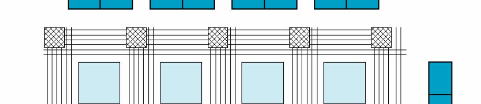
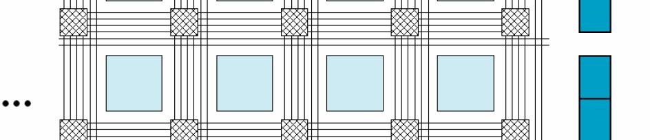
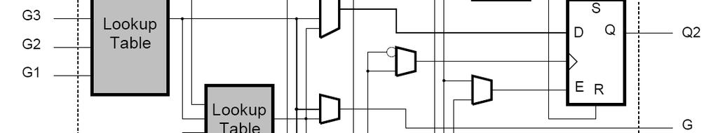
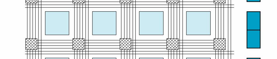
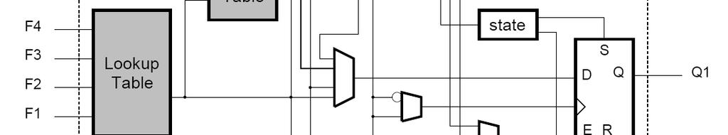
5 Field-Programmable Gate Array (FPGA) 5/32 An array of programmable basic logic cells surrounded by programmable interconnect Xilinx XC4000 Configurable Logic Block (CLB).
6 Hardware Description Lang. (HDL) 6/32 Hardware Description Language (HDL) A software programming language used to model a piece of hardware Verilog-HDL, VHDL, SystemC, ABEL VHDL(VHSIC HDL) 1980 USA Department of Defence 1987 IEEE Standard 1076 Verilog HDL 1981 Gateway Design Automation 1995 IEEE Standard 1364
7 VHDL vs. Verilog 7/32 On the surface, not much Both can be used for designing ASICs and simulating systems Both are IEEE standards and are supported by all the major EDA vendors VHDL requires longer to learn and is not so amenable to quick-and-dirty dirty coding Many engineers will one day be bi-lingual in both HDLs
8 Introduction to VHDL 8/32 Designed to describe the behavior of digital systems Used as an input to commercial synthesis tools (only subsets of VHDL are synthesizable) VHDL is concurrent HDL which provides a wide range of levels of abstraction Architectural, Algorithmic, RTL, Gate, Switch VHDL has hierarchical design units
9 VHDL Structure 9/32 Circuit module Entity declaration + architecture body Circuit Module Ports Entity Declaration Architecture (Body) Sequential, Combinational Subprograms An entity is a simple declaration of a module s inputs and outputs. An architecture is a detailed description of module s internal structure or behavior.
10 Syntax of a VHDL entity declaration 10/32 entity example1 is port t( x1, x2, x3 : in std_logic ; --input signals in1 : in integer ; val1 : out std_logic ; -- output signals Signal Name val2 : out std_logic_vector(3 down to 0) ; end example1 ; Mode Type architecture sample1 of example1 is begin -- hello world ; end sample1 ; Entity-name User-defined identifier to name the entity Signal-names User-defined identifiers to name external-interface signal
11 Syntax of a VHDL entity declaration 11/32 Mode : specifying the signal direction In : the signal is an input to the entity. Out : the signal is an output of the entity. Inout: the signal can be read as an input or an output of the entity. This mode is typically used for three-state input/output pins. Buffer: the signal is an output of the entity, and its value can also be read and written inside the entity s architecture. In or Inout Out or Inout Upper Module In Lower Module Inout Inout Out Buffer Buffer
12 Syntax of a VHDL entity declaration 12/32 Signal types library IEEE ; use IEEE.std_logic_1164.all ; std_logic(bit) : U(Uninitialized), X(Forcing Unknown), 0(Forcing 0), 1(Forcing 1), Z(High Impedance), W(Weak Unknown), L(Weak 0), H(Weak 1), _(Don't Care) std_logic_vector(bit vector) for 8bit data type : std_logic_vector(7 downto 0) integer, real, character, boolean, etc.
13 Predefined Operators 13/32 Integer Operators: + addition - Subtraction * Multiplication / division mod modulo division rem modulo remainder Abs absolute value ** exponentiation Boolean Operators: and AND or OR nand NAND nor NOR xor exclusive OR xnor exclusive nor not complementation & concatenation
14 Sequential Statement 14/32 [LABEL:] if expr then {sequential_statement} [{elsif expr then {sequential_statement}}] [else {sequential_statement}] statement}] end if [LABEL]; [LABEL:] [while expr] loop {sequential_statement} end loop [LABEL]; [LABEL:] for ID in range loop {sequential_statement} statement} end loop [LABEL]; [LABEL:]] case expr is {when choice [{ choice}] => {sequential_statement}} end case [LABEL];
15 Process Statement 15/32 Logic circuit description in architecture body process sequential statement sequential statement concurrent statement concurrent statement Consists of concurrent statement and sequential statement Process contains several sequential statement Process itself is a sort of concurrent statement Process have three different state : suspended, active, running
16 Process Statement 16/32 What s the difference? architecture con of drv is begin A <= B; A <= C; end con; architecture seq of drv is begin Process(B, C) begin A <= B A<=C end process; end con2; Multiple l driver Several signal assignment to a single signal driver Signal driver A source which determines a value of each signal A signal is updated by the driver at every source update
17 Delta Delays (1/2) 17/32 Delta time is the time between two sequential events. The time to take from assigning g a value till updated The following VHDL code makes infinite delta delay and generates a synthesis error architecture con of some is begin A_Sig <= B_Sig ; B_Sig <= A_Sig ; end con;
18 Delta Delays (2/2) 18/32 Delta delays are used to order events.
19 Architecture Style (1/4) 19/32 Behavioral Style Describes a system in terms of what it does(or how it behaves)] IF, CASE, FOR, mainly within Process statement architecture BEHAVE of COMPARE is begin process (A, B) begin if (A = B) then C <= '1' ; else C <= '0' ; end if ; end process ; end BEHAVE ; architecture BEHAVE of MUX41 is begin case sel is when "00" => Z <= i0 ; when "01" => Z <= i1 ; when "10" => Z <= i2 ; when "11" => Z <= i3 ; end case ; end BEHAVE ;
20 Architecture Style (2/4) 20/32 Dataflow Style Specifies the relationship between the input and output signals AND, OR, NOT, XOR, etc. architecture of DATAFLOW of COMPARE is begin C<=not(Axor B) ; D <= A and not B ; end DATAFLOW ;
21 Architecture Style (3/4) 21/32 Structural Style Describes a system as interconnection of predefined components, hierarchical design consists of modules and interconnections ti Component, Port Map architecture STRUCTURE of COMPARE is signal I : BIT ; component XOR2 port (X, Y: in BIT; Z: out BIT) ; end component ; component INV port (X: in BIT; Z: out BIT) ; end component ; begin U0: XOR2 port map (A, B, I) ; U1: INV port map (I, C) ; end STRUCTURE ;
22 Architecture Style (4/4) 22/32 Example of Structural Style U1 I3 architecture structure of MUX41 is I2 component MUX21 port (D1, D0, S : in std_logic; Y : out std_logic); I1 end component; I0 signal A, B : std_logic; U0 begin U0 :MUX21portmap (D0 => I0, D1 => I1, S=>sel(0), Y=>A); U1 : MUX21 port map (D0 => I2, D1 => I3, S=>sel(0), Y=>B); U2 : MUX21 port map (D0 => A, D1=>B, S=>sel(1), Y=>Z); end structure; D1 Y D0 D1 Y D0 S sel(0) B D1 D0 A sel(1) U2 Y S Z
23 VHDL Source Code: Latch 23/32 VHDL Code for Latch Library IEEE; Use IEEE.std_logic_1164.all; Entity Latch is Port(LE, Din : in std_logic; Dout :outstd std_logic); End Latch; Architecture Latch_arch of Latch is Begin Process (Din, LE) Begin If (LE= 1 ) then Dout <= Din; End if; End process; End Latch_arch;
24 VHDL Source Code : D-Flip Flop 24/32 D-flip flop triggered by rising edge library IEEE; use IEEE.std_logic_1164.all; entity d-ff is port(clk, d: in std_logic; q : out std_logic); end d-ff; architecture d-ff_arch of d-ff is begin process(clk) Rising_edge(clk) begin if(clk'event and clk = '1') then q <= d; end if; end if end process; end d-ff_arch
25 VHDL Source Code : Register 25/32 8-bit register Library IEEE; use IEEE.std_logic_1164.all; entity Reg is port(clk : in std_logic; rst : in std_logic; ld : in std_logic; d : in std_logic_vector(7 t downto 0); q : out std_logic_vector(7 downto 0)); end Reg; architecture Reg_arch of Reg is begin process(clk, rst) begin if(rst = '1') then q <= (others => '0'); elsif(clk'event and clk ='1') then if(ld = '1') then q <= d; end if; end if; end process; end Reg_arch;
26 Typical Design Flow 26/32 HDL design : behavioral or structural description of design RTL Simulation verifies logic model & data flow. The simulation is typically performed to confirm that the code is functioning as intended. At this step, no timing information is provided. Post-Synthesis Simulation : SDF(standard delay format)- timing info. of each cell in the design. The place and route tools are used for layout generation. HDL Timing Simulation(Post- Layout Sim) : after the design has completed the PnR, simulation with backannotated information.
27 Synthesis 27/32 Synthesis = Translation+Optimization+Mapping pp
")


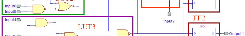
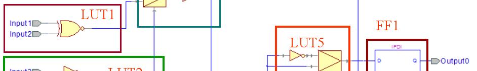
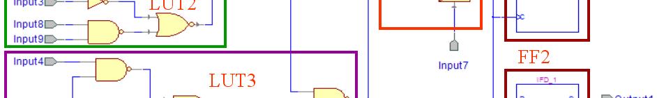
28 Mapping (1/2) 28/32 Original Netlist Possible Covering LUT Mapping from Covering
29 Mapping (2/2) 29/32 LUT0 LUT4 LUT1 LUT2 LUT5 FF1 LUT3 FF2
30 Typical Design Flow 30/32 HDL design : behavioral or structural description of design RTL Simulation verifies logic model & data flow. The simulation is typically performed to confirm that the code is functioning as intended. At this step, no timing information is provided. Post-Synthesis Simulation : SDF(standard delay format)- timing info. of each cell in the design. The place and route tools are used for layout generation. HDL Timing Simulation(Post- Layout Sim) : after the design has completed the PnR, simulation with backannotated information.


31 Placing 31/32 FPGA CLB SLICES

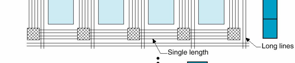
32 Routing 32/32 Programmable Connections FPGA
Lecture 3: Modeling in VHDL. EE 3610 Digital Systems
 EE 3610: Digital Systems 1 Lecture 3: Modeling in VHDL VHDL: Overview 2 VHDL VHSIC Hardware Description Language VHSIC=Very High Speed Integrated Circuit Programming language for modelling of hardware
VHDL. Official Definition: VHSIC Hardware Description Language VHISC Very High Speed Integrated Circuit
 VHDL VHDL Official Definition: VHSIC Hardware Description Language VHISC Very High Speed Integrated Circuit VHDL Alternative (Student Generated) Definition Very Hard Digital Logic language VHDL Design
Field Programmable Gate Array
 Field Programmable Gate Array System Arch 27 (Fire Tom Wada) What is FPGA? System Arch 27 (Fire Tom Wada) 2 FPGA Programmable (= reconfigurable) Digital System Component Basic components Combinational
IT T35 Digital system desigm y - ii /s - iii
 UNIT - V Introduction to Verilog Hardware Description Language Introduction HDL for combinational circuits Sequential circuits Registers and counters HDL description for binary multiplier. 5.1 INTRODUCTION
Lecture 12 VHDL Synthesis
 CPE 487: Digital System Design Spring 2018 Lecture 12 VHDL Synthesis Bryan Ackland Department of Electrical and Computer Engineering Stevens Institute of Technology Hoboken, NJ 07030 1 What is Synthesis?
Lecture 7. Standard ICs FPGA (Field Programmable Gate Array) VHDL (Very-high-speed integrated circuits. Hardware Description Language)
 VHDL (Very-high-speed integrated circuits. Hardware Description Language)") Standard ICs FPGA (Field Programmable Gate Array) VHDL (Very-high-speed integrated circuits Hardware Description Language) 1 Standard ICs PLD: Programmable Logic Device CPLD: Complex PLD FPGA: Field Programmable
Standard ICs FPGA (Field Programmable Gate Array) VHDL (Very-high-speed integrated circuits Hardware Description Language) 1 Standard ICs PLD: Programmable Logic Device CPLD: Complex PLD FPGA: Field Programmable
VHDL And Synthesis Review
 VHDL And Synthesis Review VHDL In Detail Things that we will look at: Port and Types Arithmetic Operators Design styles for Synthesis VHDL Ports Four Different Types of Ports in: signal values are read-only
Hardware Description Language VHDL (1) Introduction
 Introduction") Hardware Description Language VHDL (1) Introduction Digital Radiation Measurement and Spectroscopy NE/RHP 537 Introduction Hardware description language (HDL) Intended to describe circuits textually, for
Hardware Description Language VHDL (1) Introduction Digital Radiation Measurement and Spectroscopy NE/RHP 537 Introduction Hardware description language (HDL) Intended to describe circuits textually, for
1 ST SUMMER SCHOOL: VHDL BOOTCAMP PISA, JULY 2013
 MARIE CURIE IAPP: FAST TRACKER FOR HADRON COLLIDER EXPERIMENTS 1 ST SUMMER SCHOOL: VHDL BOOTCAMP PISA, JULY 2013 Introduction to VHDL Calliope-Louisa Sotiropoulou PhD Candidate/Researcher Aristotle University
VHDL for FPGA Design. by : Mohamed Samy
 VHDL for FPGA Design by : Mohamed Samy VHDL Vhdl is Case insensitive myvar = myvar = MYVAR IF = if = if Comments start with -- Comments can exist anywhere in the line Semi colon indicates the end of statements
Abi Farsoni, Department of Nuclear Engineering and Radiation Health Physics, Oregon State University
 Hardware description language (HDL) Intended to describe circuits textually, for a computer to read Evolved starting in the 1970s and 1980s Popular languages today include: VHDL Defined in 1980s by U.S.
C-Based Hardware Design
 LECTURE 6 In this lecture we will introduce: The VHDL Language and its benefits. The VHDL entity Concurrent and Sequential constructs Structural design. Hierarchy Packages Various architectures Examples
310/ ICTP-INFN Advanced Tranining Course on FPGA and VHDL for Hardware Simulation and Synthesis 27 November - 22 December 2006
 310/1780-10 ICTP-INFN Advanced Tranining Course on FPGA and VHDL for Hardware Simulation and Synthesis 27 November - 22 December 2006 VHDL & FPGA - Session 2 Nizar ABDALLH ACTEL Corp. 2061 Stierlin Court
Advanced Training Course on FPGA Design and VHDL for Hardware Simulation and Synthesis. 26 October - 20 November, 2009
 2065-15 Advanced Training Course on FPGA Design and VHDL for Hardware Simulation and Synthesis 26 October - 20 November, 2009 FPGA Architectures & VHDL Introduction to Synthesis Nizar Abdallah ACTEL Corp.2061
Lecture 4. VHDL Fundamentals. George Mason University
 Lecture 4 VHDL Fundamentals George Mason University Required reading P. Chu, RTL Hardware Design using VHDL Chapter 3, Basic Language Constructs of VHDL 2 Design Entity ECE 448 FPGA and ASIC Design with
ECE4401 / CSE3350 ECE280 / CSE280 Digital Design Laboratory
 ECE4401 / CSE3350 ECE280 / CSE280 Digital Design Laboratory Instructor John Chandy Office: ITEB 437 Office Hours: W10-12 Tel: (860) 486-5047 Email: john.chandy@uconn chandy@uconn.edu Class home page: HuskyCT
Synthesis from VHDL. Krzysztof Kuchcinski Department of Computer Science Lund Institute of Technology Sweden
 Synthesis from VHDL Krzysztof Kuchcinski Krzysztof.Kuchcinski@cs.lth.se Department of Computer Science Lund Institute of Technology Sweden March 23, 2006 Kris Kuchcinski (LTH) Synthesis from VHDL March
CSE 260 Introduction to Digital Logic and Computer Design. Exam 1. Your name 2/13/2014
 CSE 260 Introduction to Digital Logic and Computer Design Jonathan Turner Exam 1 Your name 2/13/2014 1. (10 points) Draw a logic diagram that implements the expression A(B+C)(C +D)(B+D ) directly (do not
Hardware Synthesis. References
 Hardware Synthesis MidiaReshadi CE Department Science and research branch of Islamic Azad University Email: ce.srbiau@gmail.com 1 References 2 1 Chapter 1 Digital Design Using VHDL and PLDs 3 Some Definitions
SEQUENTIAL STATEMENTS
 SEQUENTIAL STATEMENTS Sequential Statements Allow to describe the behavior of a circuit as a sequence of related events Can be used to model, simulate and synthesize: Combinational logic circuits Sequential
Computer-Aided Digital System Design VHDL
 بس م اهلل الر حم ن الر حی م Iran University of Science and Technology Department of Computer Engineering Computer-Aided Digital System Design VHDL Ramin Rajaei ramin_rajaei@ee.sharif.edu Modeling Styles
Sequential Statement
 Sequential Statement Sequential Logic Output depends not only on current input values but also on previous input values. Are building blocks of; Counters Shift registers Memories Flip flops are basic sequential
FPGA for Complex System Implementation. National Chiao Tung University Chun-Jen Tsai 04/14/2011
 FPGA for Complex System Implementation National Chiao Tung University Chun-Jen Tsai 04/14/2011 About FPGA FPGA was invented by Ross Freeman in 1989 SRAM-based FPGA properties Standard parts Allowing multi-level
VHDL: RTL Synthesis Basics. 1 of 59
 VHDL: RTL Synthesis Basics 1 of 59 Goals To learn the basics of RTL synthesis. To be able to synthesize a digital system, given its VHDL model. To be able to relate VHDL code to its synthesized output.
INTRODUCTION TO VHDL. Lecture 5 & 6 Dr. Tayab Din Memon Assistant Professor Department of Electronic Engineering, MUET
 INTRODUCTION TO VHDL Lecture 5 & 6 Dr. Tayab Din Memon Assistant Professor Department of Electronic Engineering, MUET VHDL Resources Other Sources manufacturers web pages http://www.xilinx.com http://www.altera.com
ECE 545 Lecture 5. Data Flow Modeling in VHDL. George Mason University
 ECE 545 Lecture 5 Data Flow Modeling in VHDL George Mason University Required reading P. Chu, RTL Hardware Design using VHDL Chapter 4, Concurrent Signal Assignment Statements of VHDL 2 Types of VHDL Description
Introduction to VHDL
 Introduction to VHDL Agenda Introduce VHDL Basic VHDL constructs Implementing circuit functions Logic, Muxes Clocked Circuits Counters, Shifters State Machines FPGA design and implementation issues FPGA
EECE-4740/5740 Advanced VHDL and FPGA Design. Lecture 3 Concurrent and sequential statements
 EECE-4740/5740 Advanced VHDL and FPGA Design Lecture 3 Concurrent and sequential statements Cristinel Ababei Marquette University Department of Electrical and Computer Engineering Overview Components hierarchy
VHDL. Chapter 1 Introduction to VHDL. Course Objectives Affected. Outline
 Chapter 1 Introduction to VHDL VHDL VHDL - Flaxer Eli Ch 1-1 Course Objectives Affected Write functionally correct and well-documented VHDL code, intended for either simulation or synthesis, of any combinational
Topics. Midterm Finish Chapter 7
 Lecture 9 Topics Midterm Finish Chapter 7 ROM (review) Memory device in which permanent binary information is stored. Example: 32 x 8 ROM Five input lines (2 5 = 32) 32 outputs, each representing a memory
Part 4: VHDL for sequential circuits. Introduction to Modeling and Verification of Digital Systems. Memory elements. Sequential circuits
 M1 Informatique / MOSIG Introduction to Modeling and erification of Digital Systems Part 4: HDL for sequential circuits Laurence PIERRE http://users-tima.imag.fr/amfors/lpierre/m1arc 2017/2018 81 Sequential
EEL 4783: Hardware/Software Co-design with FPGAs
 EEL 4783: Hardware/Software Co-design with FPGAs Lecture 9: Short Introduction to VHDL* Prof. Mingjie Lin * Beased on notes of Turfts lecture 1 What does HDL stand for? HDL is short for Hardware Description
Verilog. What is Verilog? VHDL vs. Verilog. Hardware description language: Two major languages. Many EDA tools support HDL-based design
 Verilog What is Verilog? Hardware description language: Are used to describe digital system in text form Used for modeling, simulation, design Two major languages Verilog (IEEE 1364), latest version is
CSCI Lab 3. VHDL Syntax. Due: Tuesday, week6 Submit to: \\fs2\csci250\lab-3\
 CSCI 250 - Lab 3 VHDL Syntax Due: Tuesday, week6 Submit to: \\fs2\csci250\lab-3\ Objectives 1. Learn VHDL Valid Names 2. Learn the presentation of Assignment and Comments 3. Learn Modes, Types, Array,
VHDL: A Crash Course
 VHDL: A Crash Course Dr. Manuel Jiménez With contributions by: Irvin Ortiz Flores Electrical and Computer Engineering Department University of Puerto Rico - Mayaguez Outline Background Program Structure
ECE 545 Lecture 8. Data Flow Description of Combinational-Circuit Building Blocks. George Mason University
 ECE 545 Lecture 8 Data Flow Description of Combinational-Circuit Building Blocks George Mason University Required reading P. Chu, RTL Hardware Design using VHDL Chapter 7, Combinational Circuit Design:
!"#$%&&"'(')"*+"%,%-".#"'/"'.001$$"
*+%,%-.#'/'.001$$") !"#$%&&"'(')"*+"%,%-".#"'/"'.001$$"!!"#$%&'#()#*+"+#,-."/0110#230#4."50",+"+#)6# 6+-+#(.6+-0#)4475.8)60#0/#.65-0#230#9+**+"+# 2.48).-0#(.6+-0#! 2+"*5."5*:#,."/0110#;)**0! *),".6*:#-.99-0*0"5."+#2+660,.40"5)#;)*)2)#
!"#$%&&"'(')"*+"%,%-".#"'/"'.001$$"!!"#$%&'#()#*+"+#,-."/0110#230#4."50",+"+#)6# 6+-+#(.6+-0#)4475.8)60#0/#.65-0#230#9+**+"+# 2.48).-0#(.6+-0#! 2+"*5."5*:#,."/0110#;)**0! *),".6*:#-.99-0*0"5."+#2+660,.40"5)#;)*)2)#
ECE 331 Digital System Design
 ECE 331 Digital System Design Tristate Buffers, Read-Only Memories and Programmable Logic Devices (Lecture #17) The slides included herein were taken from the materials accompanying Fundamentals of Logic
Very High Speed Integrated Circuit Har dware Description Language
 Very High Speed Integrated Circuit Har dware Description Language Industry standard language to describe hardware Originated from work in 70 s & 80 s by the U.S. Departm ent of Defence Root : ADA Language
FPGA Design Challenge :Techkriti 14 Digital Design using Verilog Part 1
 FPGA Design Challenge :Techkriti 14 Digital Design using Verilog Part 1 Anurag Dwivedi Digital Design : Bottom Up Approach Basic Block - Gates Digital Design : Bottom Up Approach Gates -> Flip Flops Digital
Lattice VHDL Training
 Lattice Part I February 2000 1 VHDL Basic Modeling Structure February 2000 2 VHDL Design Description VHDL language describes a digital system as a set of modular blocks. Each modular block is described
Control and Datapath 8
 Control and Datapath 8 Engineering attempts to develop design methods that break a problem up into separate steps to simplify the design and increase the likelihood of a correct solution. Digital system
What is Verilog HDL? Lecture 1: Verilog HDL Introduction. Basic Design Methodology. What is VHDL? Requirements
 What is Verilog HDL? Lecture 1: Verilog HDL Introduction Verilog Hardware Description Language(HDL)? A high-level computer language can model, represent and simulate digital design Hardware concurrency
FPGAs in a Nutshell - Introduction to Embedded Systems-
 FPGAs in a Nutshell - Introduction to Embedded Systems- Dipl.- Ing. Falk Salewski Lehrstuhl Informatik RWTH Aachen salewski@informatik.rwth-aachen.de Winter term 6/7 Contents History FPGA architecture
VHDL simulation and synthesis
 VHDL simulation and synthesis How we treat VHDL in this course You will not become an expert in VHDL after taking this course The goal is that you should learn how VHDL can be used for simulation and synthesis
Lecture 4. VHDL Fundamentals. Required reading. Example: NAND Gate. Design Entity. Example VHDL Code. Design Entity
 Required reading Lecture 4 VHDL Fundamentals P. Chu, RTL Hardware Design using VHDL Chapter 3, Basic Language Constructs of VHDL George Mason University 2 Example: NAND Gate Design Entity a b z a b z 0
Introduction to VHDL #3
 ECE 322 Digital Design with VHDL Introduction to VHDL #3 Lecture 7 & 8 VHDL Modeling Styles VHDL Modeling Styles Dataflow Concurrent statements Structural Components and interconnects Behavioral (sequential)
ACS College of Engineering. Department of Biomedical Engineering. Logic Design Lab pre lab questions ( ) Cycle-1
 Cycle-1") ACS College of Engineering Department of Biomedical Engineering Logic Design Lab pre lab questions (2015-2016) Cycle-1 1. What is a combinational circuit? 2. What are the various methods of simplifying
ACS College of Engineering Department of Biomedical Engineering Logic Design Lab pre lab questions (2015-2016) Cycle-1 1. What is a combinational circuit? 2. What are the various methods of simplifying
Introduction to VHDL #1
 ECE 3220 Digital Design with VHDL Introduction to VHDL #1 Lecture 3 Introduction to VHDL The two Hardware Description Languages that are most often used in industry are: n VHDL n Verilog you will learn
HDL. Hardware Description Languages extensively used for:
 HDL Hardware Description Languages extensively used for: Describing (digital) hardware (formal documentation) Simulating it Verifying it Synthesizing it (first step of modern design flow) 2 main options:
Contents. Appendix D VHDL Summary Page 1 of 23
 Appendix D VHDL Summary Page 1 of 23 Contents Appendix D VHDL Summary...2 D.1 Basic Language Elements...2 D.1.1 Comments...2 D.1.2 Identifiers...2 D.1.3 Data Objects...2 D.1.4 Data Types...2 D.1.5 Data
JUNE, JULY 2013 Fundamentals of HDL (10EC45) PART A
 PART A") JUNE, JULY 2013 Fundamentals of HDL (10EC45) Time: 3hrs Max Marks:100 Note: Answer FIVE full questions, selecting at least TWO questions from each part. PART A Q1.a. Describe VHDL scalar data types with
JUNE, JULY 2013 Fundamentals of HDL (10EC45) Time: 3hrs Max Marks:100 Note: Answer FIVE full questions, selecting at least TWO questions from each part. PART A Q1.a. Describe VHDL scalar data types with
ECE U530 Digital Hardware Synthesis. Course Accounts and Tools
 ECE U530 Digital Hardware Synthesis Prof. Miriam Leeser mel@coe.neu.edu Sept 13, 2006 Lecture 3: Basic VHDL constructs Signals, Variables, Constants VHDL Simulator and Test benches Types Reading: Ashenden
Sequential Logic - Module 5
 Sequential Logic Module 5 Jim Duckworth, WPI 1 Latches and Flip-Flops Implemented by using signals in IF statements that are not completely specified Necessary latches or registers are inferred by the
Multi-valued Logic. Standard Logic IEEE 1164 Type std_ulogic is ( U, uninitialized
 Multi-valued Logic Standard Logic IEEE 1164 Type std_ulogic is ( U, uninitialized X, unknown 0, logic 0 1, logic 1 Z, high impedance W, unknown L, logic 0 weak H, logic 1 weak - ); don t care Standard
VHDL. ELEC 418 Advanced Digital Systems Dr. Ron Hayne. Images Courtesy of Cengage Learning
 VHDL ELEC 418 Advanced Digital Systems Dr. Ron Hayne Images Courtesy of Cengage Learning Design Flow 418_02 2 VHDL Modules 418_02 3 VHDL Libraries library IEEE; use IEEE.std_logic_1164.all; std_logic Single-bit
Lecture 4: Modeling in VHDL (Continued ) EE 3610 Digital Systems
 EE 3610 Digital Systems") EE 3610: Digital Systems 1 Lecture 4: Modeling in VHDL (Continued ) Sequential Statements Use Process process (sensitivity list) variable/constant declarations Sequential Statements end process; 2 Sequential
EE 3610: Digital Systems 1 Lecture 4: Modeling in VHDL (Continued ) Sequential Statements Use Process process (sensitivity list) variable/constant declarations Sequential Statements end process; 2 Sequential
ECE 448 Lecture 3. Combinational-Circuit Building Blocks. Data Flow Modeling of Combinational Logic
 ECE 448 Lecture 3 Combinational-Circuit Building Blocks Data Flow Modeling of Combinational Logic George Mason University Reading Required P. Chu, FPGA Prototyping by VHDL Examples Chapter 3, RT-level
CprE 583 Reconfigurable Computing
 Recap Moore FSM Example CprE / ComS 583 Reconfigurable Computing Moore FSM that recognizes sequence 10 0 1 0 1 S0 / 0 S1 / 0 1 S2 / 1 Prof. Joseph Zambreno Department of Electrical and Computer Engineering
Two HDLs used today VHDL. Why VHDL? Introduction to Structured VLSI Design
 Two HDLs used today Introduction to Structured VLSI Design VHDL I VHDL and Verilog Syntax and ``appearance'' of the two languages are very different Capabilities and scopes are quite similar Both are industrial
ECE 448 Lecture 3. Combinational-Circuit Building Blocks. Data Flow Modeling of Combinational Logic
 ECE 448 Lecture 3 Combinational-Circuit Building Blocks Data Flow Modeling of Combinational Logic George Mason University Reading Required P. Chu, FPGA Prototyping by VHDL Examples Chapter 3, RT-level
EE 459/500 HDL Based Digital Design with Programmable Logic. Lecture 4 Introduction to VHDL
 EE 459/500 HDL Based Digital Design with Programmable Logic Lecture 4 Introduction to VHDL Read before class: Chapter 2 from textbook (first part) Outline VHDL Overview VHDL Characteristics and Concepts
DIGITAL LOGIC WITH VHDL (Fall 2013) Unit 1
 Unit 1") DIGITAL LOGIC WITH VHDL (Fall 23) Unit DESIGN FLOW DATA TYPES LOGIC GATES WITH VHDL TESTBENCH GENERATION DESIGN FLOW Design Entry: We specify the logic circuit using a Hardware Description Language (e.g.,
DIGITAL LOGIC WITH VHDL (Fall 23) Unit DESIGN FLOW DATA TYPES LOGIC GATES WITH VHDL TESTBENCH GENERATION DESIGN FLOW Design Entry: We specify the logic circuit using a Hardware Description Language (e.g.,
ECE 545 Lecture 12. FPGA Resources. George Mason University
 ECE 545 Lecture 2 FPGA Resources George Mason University Recommended reading 7 Series FPGAs Configurable Logic Block: User Guide Overview Functional Details 2 What is an FPGA? Configurable Logic Blocks
Outline. CPE/EE 422/522 Advanced Logic Design L05. Review: General Model of Moore Sequential Machine. Review: Mealy Sequential Networks.
 Outline CPE/EE 422/522 Advanced Logic Design L05 Electrical and Computer Engineering University of Alabama in Huntsville What we know Combinational Networks Sequential Networks: Basic Building Blocks,
Digital Systems Design
 Digital Systems Design Review of Combinatorial Circuit Building Blocks: VHDL for Combinational Circuits Dr. D. J. Jackson Lecture 2-1 Introduction to VHDL Designer writes a logic circuit description in
Chapter 2 Basic Logic Circuits and VHDL Description
 Chapter 2 Basic Logic Circuits and VHDL Description We cannot solve our problems with the same thinking we used when we created them. ----- Albert Einstein Like a C or C++ programmer don t apply the logic.
ECE 2300 Digital Logic & Computer Organization. More Sequential Logic Verilog
 ECE 2300 Digital Logic & Computer Organization Spring 2018 More Sequential Logic Verilog Lecture 7: 1 Announcements HW3 will be posted tonight Prelim 1 Thursday March 1, in class Coverage: Lectures 1~7
[VARIABLE declaration] BEGIN. sequential statements
![[VARIABLE declaration] BEGIN. sequential statements](/thumbs/89/98890993.jpg "[VARIABLE declaration] BEGIN. sequential statements") PROCESS statement (contains sequential statements) Simple signal assignment statement
PROCESS statement (contains sequential statements) Simple signal assignment statement
Luleå University of Technology Kurskod SMD098 Datum Skrivtid
 Luleå University of Technology Kurskod SMD098 Datum 2001-12-17 Skrivtid 14.00 18.00 Tentamen i Beräkningstrukturer Antal uppgifter: 6 Max poäng: 35 Lärare: Jonas Thor Telefon: 2549 Tillåtna hjälpmedel:
CSE 260 Introduction to Digital Logic and Computer Design. Exam 1 Solutions
 CSE 6 Introduction to igital Logic and Computer esign Exam Solutions Jonathan Turner /3/4. ( points) raw a logic diagram that implements the expression (B+C)(C +)(B+ ) directly (do not simplify first),
Today. Comments about assignment Max 1/T (skew = 0) Max clock skew? Comments about assignment 3 ASICs and Programmable logic Others courses
 Max clock skew? Comments about assignment 3 ASICs and Programmable logic Others courses") Today Comments about assignment 3-43 Comments about assignment 3 ASICs and Programmable logic Others courses octor Per should show up in the end of the lecture Mealy machines can not be coded in a single
Today Comments about assignment 3-43 Comments about assignment 3 ASICs and Programmable logic Others courses octor Per should show up in the end of the lecture Mealy machines can not be coded in a single
5. 0 VHDL OPERATORS. The above classes are arranged in increasing priority when parentheses are not used.
 Filename= ch5.doc 5. 0 VHDL OPERATORS There are seven groups of predefined VHDL operators: 1. Binary logical operators: and or nand nor xor xnor 2. Relational operators: = /= < >= 3. Shifts operators:
Synthesizable Verilog
 Synthesizable Verilog Courtesy of Dr. Edwards@Columbia, and Dr. Franzon@NCSU http://csce.uark.edu +1 (479) 575-6043 yrpeng@uark.edu Design Methodology Structure and Function (Behavior) of a Design HDL
VHDL VS VERILOG.
 1 VHDL VS VERILOG http://www.cse.cuhk.edu.hk/~mcyang/teaching.html 2 VHDL & Verilog They are both hardware description languages for modeling hardware. They are each a notation to describe the behavioral
Design Entry: Schematic Capture and VHDL ENG241: Digital Design Week #4
 Design Entry: Schematic Capture and VHDL ENG241: Digital Design Week #4 1 References Kenneth Sort, VHDL For Engineers, Prentice Hall, 2009. Peter Ashenden, The designer s guide to VHDL, 2 nd edition, Morgan
VHDL Synthesis Reference
 VHDL Synthesis Reference Old Content - visit altium.com/documentation Mod ifi ed by on 6- Nov -20 13 The following content has been imported from Legacy Help systems and is in the process of being checked
Lecture 2 Hardware Description Language (HDL): VHSIC HDL (VHDL)
: VHSIC HDL (VHDL)") Lecture 2 Hardware Description Language (HDL): VHSIC HDL (VHDL) Pinit Kumhom VLSI Laboratory Dept. of Electronic and Telecommunication Engineering (KMUTT) Faculty of Engineering King Mongkut s University
Lecture 2 Hardware Description Language (HDL): VHSIC HDL (VHDL) Pinit Kumhom VLSI Laboratory Dept. of Electronic and Telecommunication Engineering (KMUTT) Faculty of Engineering King Mongkut s University
Digital Design with FPGAs. By Neeraj Kulkarni
 Digital Design with FPGAs By Neeraj Kulkarni Some Basic Electronics Basic Elements: Gates: And, Or, Nor, Nand, Xor.. Memory elements: Flip Flops, Registers.. Techniques to design a circuit using basic
VHDL. VHDL History. Why VHDL? Introduction to Structured VLSI Design. Very High Speed Integrated Circuit (VHSIC) Hardware Description Language
 Hardware Description Language") VHDL Introduction to Structured VLSI Design VHDL I Very High Speed Integrated Circuit (VHSIC) Hardware Description Language Joachim Rodrigues A Technology Independent, Standard Hardware description Language
VHDL Introduction to Structured VLSI Design VHDL I Very High Speed Integrated Circuit (VHSIC) Hardware Description Language Joachim Rodrigues A Technology Independent, Standard Hardware description Language
Department of Electronics & Communication Engineering Lab Manual E-CAD Lab
 Department of Electronics & Communication Engineering Lab Manual E-CAD Lab Prasad V. Potluri Siddhartha Institute of Technology (Sponsored by: Siddhartha Academy of General & Technical Education) Affiliated
8 Register, Multiplexer and
 8 Register, Multiplexer and Three-State Inference HDL Compiler can infer Registers (latches and flip flops) Multiplexers Three state gates This chapter discusses methods of inferring different types of
Speaker: Kayting Adviser: Prof. An-Yeu Wu Date: 2009/11/23
 98-1 Under-Graduate Project Synthesis of Combinational Logic Speaker: Kayting Adviser: Prof. An-Yeu Wu Date: 2009/11/23 What is synthesis? Outline Behavior Description for Synthesis Write Efficient HDL
Logic and Computer Design Fundamentals VHDL. Part 1 Chapter 4 Basics and Constructs
 Logic and Computer Design Fundamentals VHDL Part Chapter 4 Basics and Constructs Charles Kime & Thomas Kaminski 24 Pearson Education, Inc. Terms of Use (Hyperlinks are active in View Show mode) Overview
Verilog introduction. Embedded and Ambient Systems Lab
 Verilog introduction Embedded and Ambient Systems Lab Purpose of HDL languages Modeling hardware behavior Large part of these languages can only be used for simulation, not for hardware generation (synthesis)
RTL Coding General Concepts
 RTL Coding General Concepts Typical Digital System 2 Components of a Digital System Printed circuit board (PCB) Embedded d software microprocessor microcontroller digital signal processor (DSP) ASIC Programmable
ECE 448 Lecture 4. Sequential-Circuit Building Blocks. Mixing Description Styles
 ECE 448 Lecture 4 Sequential-Circuit Building Blocks Mixing Description Styles George Mason University Reading Required P. Chu, FPGA Prototyping by VHDL Examples Chapter 4, Regular Sequential Circuit Recommended
Hardware Description Languages. Modeling Complex Systems
 Hardware Description Languages Modeling Complex Systems 1 Outline (Raising the Abstraction Level) The Process Statement if-then, if-then-else, if-then-elsif, case, while, for Sensitivity list Signals vs.
DIGITAL CIRCUIT LOGIC UNIT 9: MULTIPLEXERS, DECODERS, AND PROGRAMMABLE LOGIC DEVICES
 DIGITAL CIRCUIT LOGIC UNIT 9: MULTIPLEXERS, DECODERS, AND PROGRAMMABLE LOGIC DEVICES 1 Learning Objectives 1. Explain the function of a multiplexer. Implement a multiplexer using gates. 2. Explain the
Introduction to Verilog HDL. Verilog 1
 Introduction to HDL Hardware Description Language (HDL) High-Level Programming Language Special constructs to model microelectronic circuits Describe the operation of a circuit at various levels of abstraction
Timing in synchronous systems
 BO 1 esign of sequential logic Outline Timing in synchronous networks Synchronous processes in VHL VHL-code that introduces latches andf flip-flops Initialization of registers Mealy- and Moore machines
A Brief Introduction to Verilog Hardware Definition Language (HDL)
") www.realdigital.org A Brief Introduction to Verilog Hardware Definition Language (HDL) Forward Verilog is a Hardware Description language (HDL) that is used to define the structure and/or behavior of digital
www.realdigital.org A Brief Introduction to Verilog Hardware Definition Language (HDL) Forward Verilog is a Hardware Description language (HDL) that is used to define the structure and/or behavior of digital
INTRODUCTION TO FPGA ARCHITECTURE
 3/3/25 INTRODUCTION TO FPGA ARCHITECTURE DIGITAL LOGIC DESIGN (BASIC TECHNIQUES) a b a y 2input Black Box y b Functional Schematic a b y a b y a b y 2 Truth Table (AND) Truth Table (OR) Truth Table (XOR)
A bird s eye view on VHDL!
 Advanced Topics on Heterogeneous System Architectures A bird s eye view on VHDL Politecnico di Milano Conference Room, Bld 20 19 November, 2015 Antonio R. Miele Marco D. Santambrogio Politecnico di Milano
Lecture 1: VHDL Quick Start. Digital Systems Design. Fall 10, Dec 17 Lecture 1 1
 Lecture 1: VHDL Quick Start Digital Systems Design Fall 10, Dec 17 Lecture 1 1 Objective Quick introduction to VHDL basic language concepts basic design methodology Use The Student s Guide to VHDL or The
VHDL for Logic Synthesis
 VHDL for Logic Synthesis Overview Design Flow for Hardware Design VHDL coding for synthesis General guidelines for hardware designers This lecture includes the content from: Nitin Yogi, Modelling for Synthesis
ELCT 501: Digital System Design
 ELCT 501: Digital System Lecture 4: CAD tools (Continued) Dr. Mohamed Abd El Ghany, Basic VHDL Concept Via an Example Problem: write VHDL code for 1-bit adder 4-bit adder 2 1-bit adder Inputs: A (1 bit)
PINE TRAINING ACADEMY
 PINE TRAINING ACADEMY Course Module A d d r e s s D - 5 5 7, G o v i n d p u r a m, G h a z i a b a d, U. P., 2 0 1 0 1 3, I n d i a Digital Logic System Design using Gates/Verilog or VHDL and Implementation
CDA 4253 FPGA System Design Introduction to VHDL. Hao Zheng Dept of Comp Sci & Eng USF
 CDA 4253 FPGA System Design Introduction to VHDL Hao Zheng Dept of Comp Sci & Eng USF Reading P. Chu, FPGA Prototyping by VHDL Examples Chapter 1, Gate-level combinational circuits Two purposes of using
Getting Started with VHDL
 Getting Started with VHDL VHDL code is composed of a number of entities Entities describe the interface of the component Entities can be primitive objects or complex objects Architectures are associated