Sequential Logic - Module 5
|
|
|
- Tyrone Stanley
- 5 years ago
- Views:
Transcription
1 Sequential Logic Module 5 Jim Duckworth, WPI 1
2 Latches and Flip-Flops Implemented by using signals in IF statements that are not completely specified Necessary latches or registers are inferred by the synthesis tool. Transparent Latch Edge-triggered flip-flop Reset Asynchronous Synchronous Counters Shift Registers Finite State Machines Jim Duckworth, WPI 2
3 Combinational Logic - review All input signals specified in sensitivity list All conditions evaluated PROCESS (a, b, sel) IF sel = 1 THEN y <= a ; ELSE y <= b ; END PROCESS; a b sel y Jim Duckworth, WPI 3
4 Transparent (Flow-Through) Latch IF statement not completely specified - missing ELSE part Output follows input when enable high but stores old value when enable goes low PROCESS (enable, d) IF enable = 1 THEN q <= d; END PROCESS; d enable q enable d q Jim Duckworth, WPI 4
5 Edge-Triggered Flip-Flop Positive edge-triggered flip flop PROCESS (clk) IF clk EVENT AND clk = 1 THEN q <= d; END PROCESS; d clk q d clk q Jim Duckworth, WPI 5
6 Flip-flop (cont d) clk EVENT is an example of a function signal attribute returns TRUE if event (change in value) occurred on signal can be used to detect an edge when combined with a further test (AND clk = 1 ) we can determine that it was a rising edge Note: not strictly necessary in this example but good practice makes VHDL description easier to read may be required if additional signals added later Jim Duckworth, WPI 6
7 Clocked Process - general format ARCHITECTURE behav OF flip-flop IS PROCESS (clock signal, [asynchronous signals]) IF asynchronous conditions THEN sequential statements for reset or preset; ELSIF clock_edge THEN sequential statements for clock_edge; END PROCESS; END behav; Sensitivity list includes clk and asynchronous signals All signal assignments in process result in flip-flops Jim Duckworth, WPI 8
8 Adding asynchronous clear and preset signals ENTITY dtype IS PORT(clk, d, clr, pre : IN std_logic; q, n_q : OUT std_logic); END dtype; ARCHITECTURE behav OF dtype IS SIGNAL temp_q : std_logic; -- internal signal PROCESS (clk, clr, pre) IF clr = 1 THEN -- clear operation temp_q <= 0 ; ELSIF pre = 1 THEN -- preset operation temp_q <= 1 ; ELSIF clk EVENT AND clk = 1 THEN -- clock temp_q <= d; END PROCESS; q <= temp_q; n_q <= NOT temp_q; END behav; Jim Duckworth, WPI 9
9 Flip-flop (cont d) Variations can be easily achieved negative-triggered clock synchronous clear ARCHITECTURE behav OF flip-flop IS PROCESS (clk) IF clk EVENT AND clk = 0 THEN IF n_clr = 0 THEN q <= 0 ELSE q <= d; END PROCESS; END behav; Jim Duckworth, WPI 12
10 Counter Five-bit counter with asynchronous reset Using integer type (could also use std_logic_vector with unsigned library) LIBRARY ieee; USE ieee.std_logic_1164.all; ENTITY count17 IS PORT(clk, reset : IN std_logic; q : OUT integer RANGE 0 TO 17); END count17; Jim Duckworth, WPI 13
11 Counter (cont d) ARCHITECTURE behav OF count17 is SIGNAL count : integer RANGE 0 TO 17; PROCESS(clk, reset) IF reset = 1 THEN count <= 0; ELSIF clk EVENT AND clk = 1 THEN IF count = 17 THEN count <= 0; ELSE count <= count + 1; END PROCESS; q <= count; -- concurrent statement END behav; -- internal signal -- sensitivity list -- asynch reset -- positive edge -- terminal count Jim Duckworth, WPI 14


12 5-bit Counter Synthesis Jim Duckworth, WPI 15


13 5-Bit Counter Schematic Jim Duckworth, WPI 16
14 Counter with Preset (Synchronous Clear) ENTITY cnt4pre IS PORT(clk, pre, n_clr : IN std_logic; d : IN integer RANGE 0 TO 12; q : OUT integer RANGE 0 TO 12); END cnt4pre; ARCHITECTURE behav OF cnt4pre IS SIGNAL count : integer RANGE 0 TO 12; PROCESS (clk) IF clk EVENT AND clk = 1 THEN IF n_clr = 0 THEN -- synchronous clear count <= 0; ELSIF pre = 1 THEN count <= d; ELSE IF count = 12 THEN count <= 0; ELSE count <= count + 1; END PROCESS; q <= count; END behav; Jim Duckworth, WPI 17

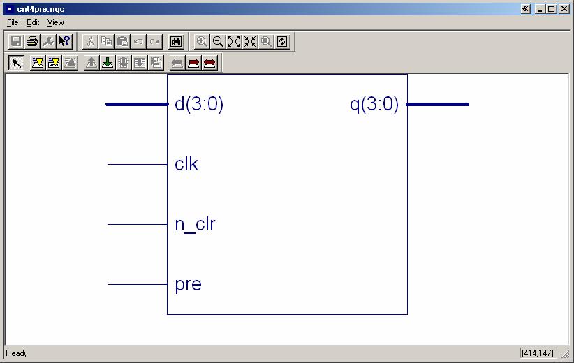
15 Schematic Jim Duckworth, WPI 19
 Jim Duckworth,")
16 Behavioral Simulation Results (ISE) Jim Duckworth, WPI 22
17 Shift Registers Example of 4-bit shift register with parallel load shift left and shift right capability LIBRARY ieee; USE ieee.std_logic_1164.all; ENTITY shift IS PORT(load, clk, left_right : IN std_logic; d : IN std_logic_vector(3 DOWNTO 0); q : OUT std_logic_vector(3 DOWNTO 0)); END shift; Jim Duckworth, WPI 25
18 Shift Register (cont d) ARCHITECTURE behav OF shift IS SIGNAL temp : std_logic_vector(3 DOWNTO 0); PROCESS(clk) -- all operations synchronous IF clk'event AND clk = '1' THEN IF load = '1' THEN temp <= d; ELSIF left_right = '0' THEN -- shift left; temp <= temp(2 DOWNTO 0) & '0'; ELSE temp <= '0' & temp(3 DOWNTO 1); -- right END PROCESS; q <= temp; END behav; Jim Duckworth, WPI 26


19 Synthesis Results Jim Duckworth, WPI 27

20 Shift Register - Behavioral Simulation Jim Duckworth, WPI 29
21 State Machines Module 6 Jim Duckworth, WPI 1 State Machines - Module 6
22 State Machines Block Diagram - Moore Machine Outputs determined by current state Inputs Next State Logic State Memory Output Logic Outputs Clock Reset Current State Jim Duckworth, WPI 3 State Machines - Module 6
23 State Machine (cont d) Current state determined by state memory (flip-flops) Outputs are decoded from the value of the current state combinational logic Next state is determined by current state and inputs at time of next triggering clock edge. Jim Duckworth, WPI 4 State Machines - Module 6
24 Simple State Machine Example RESET=1 EN=0 EN=1 S0 C=0 EN=1 S3 C=1 S1 C=0 EN=0 EN=0 EN=1 S2 C=0 EN=1 EN=0 Jim Duckworth, WPI 5 State Machines - Module 6
25 State Machine Coding Style ENTITY sm1 IS PORT(clk, reset, en c END sm1; : IN std_logic; : OUT std_logic); ARCHITECTURE behav OF sm1 IS TYPE state_type IS (s0, s1, s2, s3); -- enumerated type SIGNAL current_state, next_state : state_type; state_memory: PROCESS(clk, reset) -- see next slides for detail END PROCESS state_memory; next_state_logic: PROCESS(en, current_state) END PROCESS next_state_logic; END behav; Jim Duckworth, WPI 7 State Machines - Module 6
26 state_memory Process state_memory: PROCESS(clk, reset) IF reset = '1' THEN current_state <= s0; ELSIF clk'event AND clk = '1' THEN -- triggering edge current_state <= next_state; END PROCESS state_memory; Jim Duckworth, WPI 8 State Machines - Module 6
27 next_state Process next_state_logic: PROCESS(en, current_state) CASE current_state IS WHEN s0 => IF en = '1' THEN next_state <= s1; ELSE next_state <= s0; c <= 0 ; WHEN s1 => IF en = '1' THEN next_state <= s2; ELSE next_state <= s1; c <= 0 ; WHEN s2 => IF en = '1' THEN next_state <= s3; ELSE next_state <= s2; c <= 0 ; WHEN s3 => IF en = '1' THEN next_state <= s0; ELSE next_state <= s3; c <= 1 ; END CASE; END PROCESS next_state_logic; Jim Duckworth, WPI 9 State Machines - Module 6

28 SM1 VHDL Code Jim Duckworth, WPI 10 State Machines - Module 6

29 SM1- Schematic Jim Duckworth, WPI 13 State Machines - Module 6

30 Behavioral Simulation Jim Duckworth, WPI 14 State Machines - Module 6
31 State Machine - alternative coding style -- one process with one state signal ARCHITECTURE behav OF sm2 IS TYPE state_type IS (s0, s1, s2, s3); -- enumerated type SIGNAL state : state_type; PROCESS(clk, reset) IF reset = '1' THEN state <= s0; ELSIF clk'event AND clk = '1' THEN -- triggering edge CASE state IS WHEN s0 => IF en = '1' THEN state <= s1; ELSE state <= s0; c <= '0'; WHEN s1 => IF en = '1' THEN state <= s2; Jim Duckworth, WPI 28 State Machines - Module 6
32 State Machine (cont d) END PROCESS; END behav; END CASE; ELSE state <= s1; c <= '0'; WHEN s2 => IF en = '1' THEN state <= s3; ELSE state <= s2; c <= '0'; WHEN s3 => IF en = '1' THEN state <= s0; ELSE state <= s3; c <= '1'; Jim Duckworth, WPI 29 State Machines - Module 6

33 SM2 - Synthesis Results Jim Duckworth, WPI 30 State Machines - Module 6
34 Registered Outputs Output signal assignments within state machine process No glitches on registered outputs Outputs are registered in parallel with state registers Register introduces a one cycle delay Jim Duckworth, WPI 31 State Machines - Module 6
35 Block Diagram (registered outputs) Inputs Next State Logic State Memory Current State Clock Output Logic Output Register Outputs Jim Duckworth, WPI 32 State Machines - Module 6

36 Functional Simulation Jim Duckworth, WPI 33 State Machines - Module 6
37 Block Diagram (using next state logic) Inputs Next State Logic State Memory Current State Clock Output Logic Output Register Outputs Jim Duckworth, WPI 34 State Machines - Module 6
38 Three processes: Registered Outputs (no delay) state_memory PROCESS (clk, reset) ELSIF clk EVENT AND clk = 1 THEN current_state <= next_state; next_state_logic PROCESS (en, current_state) CASE current_state IS WHEN s0 => next_state <= s1; registered_output_logic (uses next state to determine outputs) PROCESS (clk, reset) ELSIF clk EVENT AND clk = 1 THEN CASE next_state IS WHEN s3 => c <= 1 ; WHEN OTHERS => c <= 0 ; Jim Duckworth, WPI 35 State Machines - Module 6
DESCRIPTION OF DIGITAL CIRCUITS USING VHDL
 DESCRIPTION OF DIGITAL CIRCUITS USING VHDL Combinatinal circuits Sequential circuits Design organization. Generic design Iterative operations Authors: Luis Entrena Arrontes, Celia López, Mario García,
Test Benches - Module 8
 Test Benches Module 8 Jim Duckworth, WPI 1 Overview We have concentrated on VHDL for synthesis Can also use VHDL as a test language Very important to conduct comprehensive verification on your design To
The University of Alabama in Huntsville ECE Department CPE Midterm Exam Solution March 2, 2006
 The University of Alabama in Huntsville ECE Department CPE 526 01 Midterm Exam Solution March 2, 2006 1. (15 points) A barrel shifter is a shift register in which the data can be shifted either by one
The University of Alabama in Huntsville ECE Department CPE Midterm Exam Solution Spring 2016
 The University of Alabama in Huntsville ECE Department CPE 526 01 Midterm Exam Solution Spring 2016 1. (15 points) Write a VHDL function that accepts a std_logic_vector of arbitrary length and an integer
The University of Alabama in Huntsville Electrical and Computer Engineering CPE/EE 422/522 Spring 2005 Homework #6 Solution
 5.3(a)(2), 5.6(c)(2), 5.2(2), 8.2(2), 8.8(2) The University of Alabama in Huntsville Electrical and Computer Engineering CPE/EE 422/522 Spring 25 Homework #6 Solution 5.3 (a) For the following SM chart:
Timing in synchronous systems
 BO 1 esign of sequential logic Outline Timing in synchronous networks Synchronous processes in VHL VHL-code that introduces latches andf flip-flops Initialization of registers Mealy- and Moore machines
VHDL And Synthesis Review
 VHDL And Synthesis Review VHDL In Detail Things that we will look at: Port and Types Arithmetic Operators Design styles for Synthesis VHDL Ports Four Different Types of Ports in: signal values are read-only
Sequential Statement
 Sequential Statement Sequential Logic Output depends not only on current input values but also on previous input values. Are building blocks of; Counters Shift registers Memories Flip flops are basic sequential
Verilog Sequential Logic. Verilog for Synthesis Rev C (module 3 and 4)
") Verilog Sequential Logic Verilog for Synthesis Rev C (module 3 and 4) Jim Duckworth, WPI 1 Sequential Logic Module 3 Latches and Flip-Flops Implemented by using signals in always statements with edge-triggered
Verilog Sequential Logic Verilog for Synthesis Rev C (module 3 and 4) Jim Duckworth, WPI 1 Sequential Logic Module 3 Latches and Flip-Flops Implemented by using signals in always statements with edge-triggered
VHDL for Modeling - Module 10
 VHDL for Modeling Module 10 Jim Duckworth, WPI 1 Overview General examples AND model Flip-flop model SRAM Model Generics DDR SDRAM Model Constraints Metastability Block Statements Just for reference Jim
Lecture 4: Modeling in VHDL (Continued ) EE 3610 Digital Systems
 EE 3610 Digital Systems") EE 3610: Digital Systems 1 Lecture 4: Modeling in VHDL (Continued ) Sequential Statements Use Process process (sensitivity list) variable/constant declarations Sequential Statements end process; 2 Sequential
EE 3610: Digital Systems 1 Lecture 4: Modeling in VHDL (Continued ) Sequential Statements Use Process process (sensitivity list) variable/constant declarations Sequential Statements end process; 2 Sequential
The University of Alabama in Huntsville ECE Department CPE Final Exam Solution Spring 2004
 The University of Alabama in Huntsville ECE Department CPE 526 01 Final Exam Solution Spring 2004 1. (15 points) An old Thunderbird car has three left and three right tail lights, which flash in unique
Part 4: VHDL for sequential circuits. Introduction to Modeling and Verification of Digital Systems. Memory elements. Sequential circuits
 M1 Informatique / MOSIG Introduction to Modeling and erification of Digital Systems Part 4: HDL for sequential circuits Laurence PIERRE http://users-tima.imag.fr/amfors/lpierre/m1arc 2017/2018 81 Sequential
VHDL in 1h. Martin Schöberl
 VHDL in 1h Martin Schöberl VHDL /= C, Java, Think in hardware All constructs run concurrent Different from software programming Forget the simulation explanation VHDL is complex We use only a small subset
VHDL Modeling Behavior from Synthesis Perspective -Part B - EL 310 Erkay Savaş Sabancı University
 VHDL Modeling Behavior from Synthesis Perspective -Part B - EL 310 Erkay Savaş Sabancı University 1 The Wait Statement Syntax wait until condition; Different forms wait until(clk event and clk = 1 ); wait
[VARIABLE declaration] BEGIN. sequential statements
![[VARIABLE declaration] BEGIN. sequential statements](/thumbs/89/98890993.jpg "[VARIABLE declaration] BEGIN. sequential statements") PROCESS statement (contains sequential statements) Simple signal assignment statement
PROCESS statement (contains sequential statements) Simple signal assignment statement
VHDL: RTL Synthesis Basics. 1 of 59
 VHDL: RTL Synthesis Basics 1 of 59 Goals To learn the basics of RTL synthesis. To be able to synthesize a digital system, given its VHDL model. To be able to relate VHDL code to its synthesized output.
ECEU530. Homework 4 due Wednesday Oct 25. ECE U530 Digital Hardware Synthesis. VHDL for Synthesis with Xilinx. Schedule
 EEU530 EE U530 igital Hardware Synthesis Lecture 11: Prof. Miriam Leeser mel@coe.neu.edu October 18, 2005 Sequential Logic in VHL Finite State Machines in VHL Project proposals due now HW 4 due Wednesday,
Schedule. ECE U530 Digital Hardware Synthesis. Rest of Semester. Midterm Question 1a
 ECE U530 Digital Hardware Synthesis Prof. Miriam Leeser mel@coe.neu.edu November 8, 2006 Midterm Average: 70 Lecture 16: Midterm Solutions Homework 6: Calculator Handshaking HW 6: Due Wednesday, November
Concurrent & Sequential Stmts. (Review)
") VHDL Introduction, Part II Figures in this lecture are from: Rapid Prototyping of Digital Systems, Second Edition James O. Hamblen & Michael D. Furman, Kluwer Academic Publishers, 2001, ISBN 0-7923-7439-
VHDL Introduction, Part II Figures in this lecture are from: Rapid Prototyping of Digital Systems, Second Edition James O. Hamblen & Michael D. Furman, Kluwer Academic Publishers, 2001, ISBN 0-7923-7439-
COE 405, Term 062. Design & Modeling of Digital Systems. HW# 1 Solution. Due date: Wednesday, March. 14
 COE 405, Term 062 Design & Modeling of Digital Systems HW# 1 Solution Due date: Wednesday, March. 14 Q.1. Consider the 4-bit carry-look-ahead adder (CLA) block shown below: A 3 -A 0 B 3 -B 0 C 3 4-bit
!"#$%&&"'(')"*+"%,%-".#"'/"'.001$$"
*+%,%-.#'/'.001$$") !"#$%&&"'(')"*+"%,%-".#"'/"'.001$$"!!"#$%&'#()#*+"+#,-."/0110#230#4."50",+"+#)6# 6+-+#(.6+-0#)4475.8)60#0/#.65-0#230#9+**+"+# 2.48).-0#(.6+-0#! 2+"*5."5*:#,."/0110#;)**0! *),".6*:#-.99-0*0"5."+#2+660,.40"5)#;)*)2)#
!"#$%&&"'(')"*+"%,%-".#"'/"'.001$$"!!"#$%&'#()#*+"+#,-."/0110#230#4."50",+"+#)6# 6+-+#(.6+-0#)4475.8)60#0/#.65-0#230#9+**+"+# 2.48).-0#(.6+-0#! 2+"*5."5*:#,."/0110#;)**0! *),".6*:#-.99-0*0"5."+#2+660,.40"5)#;)*)2)#
COVER SHEET: Total: Regrade Info: 5 (14 points) 7 (15 points) Midterm 1 Spring 2012 VERSION 1 UFID:
 7 (15 points) Midterm 1 Spring 2012 VERSION 1 UFID:") EEL 4712 Midterm 1 Spring 2012 VERSION 1 Name: UFID: IMPORTANT: Please be neat and write (or draw) carefully. If we cannot read it with a reasonable effort, it is assumed wrong. As always, the best answer
EEL 4712 Midterm 1 Spring 2012 VERSION 1 Name: UFID: IMPORTANT: Please be neat and write (or draw) carefully. If we cannot read it with a reasonable effort, it is assumed wrong. As always, the best answer
DIGITAL LOGIC DESIGN VHDL Coding for FPGAs Unit 6
 DIGITAL LOGIC DESIGN VHDL Coding for FPGAs Unit 6 FINITE STATE MACHINES (FSMs) Moore Machines Mealy Machines Algorithmic State Machine (ASM) charts FINITE STATE MACHINES (FSMs) Classification: Moore Machine:
Lecture 12 VHDL Synthesis
 CPE 487: Digital System Design Spring 2018 Lecture 12 VHDL Synthesis Bryan Ackland Department of Electrical and Computer Engineering Stevens Institute of Technology Hoboken, NJ 07030 1 What is Synthesis?
DIGITAL LOGIC WITH VHDL (Fall 2013) Unit 6
 Unit 6") DIGITAL LOGIC WITH VHDL (Fall 2013) Unit 6 FINITE STATE MACHINES (FSMs) Moore Machines Mealy Machines FINITE STATE MACHINES (FSMs) Classification: Moore Machine: Outputs depend only on the current state
DIGITAL LOGIC WITH VHDL (Fall 2013) Unit 6 FINITE STATE MACHINES (FSMs) Moore Machines Mealy Machines FINITE STATE MACHINES (FSMs) Classification: Moore Machine: Outputs depend only on the current state
FSM Components. FSM Description. HDL Coding Methods. Chapter 7: HDL Coding Techniques
 FSM Components XST features: Specific inference capabilities for synchronous Finite State Machine (FSM) components. Built-in FSM encoding strategies to accommodate your optimization goals. You may also
Introduction to VHDL #3
 ECE 322 Digital Design with VHDL Introduction to VHDL #3 Lecture 7 & 8 VHDL Modeling Styles VHDL Modeling Styles Dataflow Concurrent statements Structural Components and interconnects Behavioral (sequential)
Inferring Storage Elements
 Inferring Storage Elements In our designs, we usually use flip-flops as our storage elements. Sometimes we use latches, but not often. Latches are smaller in size, but create special, often difficult situations
8 Register, Multiplexer and
 8 Register, Multiplexer and Three-State Inference HDL Compiler can infer Registers (latches and flip flops) Multiplexers Three state gates This chapter discusses methods of inferring different types of
IT T35 Digital system desigm y - ii /s - iii
 UNIT - V Introduction to Verilog Hardware Description Language Introduction HDL for combinational circuits Sequential circuits Registers and counters HDL description for binary multiplier. 5.1 INTRODUCTION
EL 310 Hardware Description Languages Midterm
 EL 3 Hardware Description Languages Midterm 2 3 4 5 Total Name: ID : Notes: ) Please answer the questions in the provided space after each question. 2) Duration is minutes 3) Closed books and closed notes.
ECE 448 Lecture 4. Sequential-Circuit Building Blocks. Mixing Description Styles
 ECE 448 Lecture 4 Sequential-Circuit Building Blocks Mixing Description Styles George Mason University Reading Required P. Chu, FPGA Prototyping by VHDL Examples Chapter 4, Regular Sequential Circuit Recommended
CSE 260 Introduction to Digital Logic and Computer Design. Exam 1. Your name 2/13/2014
 CSE 260 Introduction to Digital Logic and Computer Design Jonathan Turner Exam 1 Your name 2/13/2014 1. (10 points) Draw a logic diagram that implements the expression A(B+C)(C +D)(B+D ) directly (do not
EEL 4712 Digital Design Test 1 Spring Semester 2007
 IMPORTANT: Please be neat and write (or draw) carefully. If we cannot read it with a reasonable effort, it is assumed wrong. COVER SHEET: Problem: Points: 1 (15 pts) 2 (20 pts) Total 3 (15 pts) 4 (18 pts)
Sequential Circuit Design: Principle
 Sequential Circuit Design: Principle Chapter 8 1 Outline 1. Overview on sequential circuits 2. Synchronous circuits 3. Danger of synthesizing async circuit 4. Inference of basic memory elements 5. Simple
Control Unit: Binary Multiplier. Arturo Díaz-Pérez Departamento de Computación Laboratorio de Tecnologías de Información CINVESTAV-IPN
 Control Unit: Binary Multiplier Arturo Díaz-Pérez Departamento de Computación Laboratorio de Tecnologías de Información CINVESTAV-IPN Example: Binary Multiplier Two versions Hardwired control Microprogrammed
ECE 545 Lecture 6. Behavioral Modeling of Sequential-Circuit Building Blocks. George Mason University
 ECE 545 Lecture 6 Behavioral Modeling of Sequential-Circuit Building Blocks George Mason University Required reading P. Chu, RTL Hardware Design using VHDL Chapter 5.1, VHDL Process Chapter 8, Sequential
EE 459/500 HDL Based Digital Design with Programmable Logic. Lecture 6 Combinational and sequential circuits
 EE 459/5 HL Based igital esign with Programmable Logic Lecture 6 ombinational and sequential circuits Read before class: hapter 2 from textbook Overview ombinational circuits Multiplexer, decoders, encoders,
Synthesis from VHDL. Krzysztof Kuchcinski Department of Computer Science Lund Institute of Technology Sweden
 Synthesis from VHDL Krzysztof Kuchcinski Krzysztof.Kuchcinski@cs.lth.se Department of Computer Science Lund Institute of Technology Sweden March 23, 2006 Kris Kuchcinski (LTH) Synthesis from VHDL March
Example 58: Traffic Lights
 208 Chapter 8 Listing 8.7(cont.) doorlock2_top.vhd btn012
Problem Set 10 Solutions
 CSE 260 Digital Computers: Organization and Logical Design Problem Set 10 Solutions Jon Turner thru 6.20 1. The diagram below shows a memory array containing 32 words of 2 bits each. Label each memory
EITF35: Introduction to Structured VLSI Design
 EITF35: Introduction to Structured VLSI Design Part 2.2.2: VHDL-3 Liang Liu liang.liu@eit.lth.se 1 Outline Inference of Basic Storage Element Some Design Examples DFF with enable Counter Coding Style:
Luleå University of Technology Kurskod SMD152 Datum Skrivtid
 Luleå University of Technology Kurskod SMD152 Datum 2003-10-24 Skrivtid 9.00 13.00 1 Manual synthesis (10 p, 2 p each) Here you are given five different VHDL models. Your task is to draw the schematics
Two HDLs used today VHDL. Why VHDL? Introduction to Structured VLSI Design
 Two HDLs used today Introduction to Structured VLSI Design VHDL I VHDL and Verilog Syntax and ``appearance'' of the two languages are very different Capabilities and scopes are quite similar Both are industrial
DESIGN AND IMPLEMENTATION OF MOD-6 SYNCHRONOUS COUNTER USING VHDL
 Arid Zone Journal of Engineering, Technology and Environment. August, 2013; Vol. 9, 17-26 DESIGN AND IMPLEMENTATION OF MOD-6 SYNCHRONOUS COUNTER USING VHDL Dibal, P.Y. (Department of Computer Engineering,
Nanosistemų programavimo kalbos 5 paskaita. Sekvencinių schemų projektavimas
 Nanosistemų programavimo kalbos 5 paskaita Sekvencinių schemų projektavimas Terminai Combinational circuit kombinacinė schema (be atminties elementų) Sequential circuit nuosekli (trigerinė, sekvencinė)
Summary of FPGA & VHDL
 FYS4220/9220 Summary of FPGA & VHDL Lecture #6 Jan Kenneth Bekkeng, University of Oslo - Department of Physics 16.11.2011 Curriculum (VHDL & FPGA part) Curriculum (Syllabus) defined by: Lectures Lecture6:
VHDL. VHDL History. Why VHDL? Introduction to Structured VLSI Design. Very High Speed Integrated Circuit (VHSIC) Hardware Description Language
 Hardware Description Language") VHDL Introduction to Structured VLSI Design VHDL I Very High Speed Integrated Circuit (VHSIC) Hardware Description Language Joachim Rodrigues A Technology Independent, Standard Hardware description Language
VHDL Introduction to Structured VLSI Design VHDL I Very High Speed Integrated Circuit (VHSIC) Hardware Description Language Joachim Rodrigues A Technology Independent, Standard Hardware description Language
Field Programmable Gate Array
 Field Programmable Gate Array System Arch 27 (Fire Tom Wada) What is FPGA? System Arch 27 (Fire Tom Wada) 2 FPGA Programmable (= reconfigurable) Digital System Component Basic components Combinational
SEQUENTIAL STATEMENTS
 SEQUENTIAL STATEMENTS Sequential Statements Allow to describe the behavior of a circuit as a sequence of related events Can be used to model, simulate and synthesize: Combinational logic circuits Sequential
ECE Digital Design Laboratory. Lecture 3 Finite State Machines!
 ECE 4401 - Digital Design Laboratory Lecture 3 Finite State Machines! 1!!!! Synchronous Sequential Circuits!!! Synchronous sequential logic circuits are realized using combinational logic and storage elements
CprE 583 Reconfigurable Computing
 Recap 4:1 Multiplexer CprE / ComS 583 Reconfigurable Computing Prof. Joseph Zambreno Department of Electrical and Computer Engineering Iowa State University Lecture #18 VHDL for Synthesis I LIBRARY ieee
EITF35: Introduction to Structured VLSI Design
 EITF35: Introduction to Structured VLSI Design Part 2.2.2: VHDL-3 Liang Liu liang.liu@eit.lth.se 1 Outline Inference of Basic Storage Element Some Design Examples DFF with enable Counter Coding Style:
State Machine Descriptions
 State Machine Descriptions Can be modelled using many different coding styles Style guidelines available for Moore or Mealy type machines Several encoding schemes for state variables used in FSM descriptions
Department of Electronics & Communication Engineering Lab Manual E-CAD Lab
 Department of Electronics & Communication Engineering Lab Manual E-CAD Lab Prasad V. Potluri Siddhartha Institute of Technology (Sponsored by: Siddhartha Academy of General & Technical Education) Affiliated
In our case Dr. Johnson is setting the best practices
 VHDL Best Practices Best Practices??? Best practices are often defined by company, toolset or device In our case Dr. Johnson is setting the best practices These rules are for Class/Lab purposes. Industry
Counters. Counter Types. Variations. Modulo Gray Code BCD (Decimal) Decade Ring Johnson (twisted ring) LFSR
 Decade Ring Johnson (twisted ring) LFSR") CE 1911 Counters Counter Types Modulo Gray Code BC (ecimal) ecade Ring Johnson (twisted ring) LFSR Variations Asynchronous / Synchronous Up/own Loadable 2 tj Modulo-n (n = a power of 2) Asynchronous Count
CE 1911 Counters Counter Types Modulo Gray Code BC (ecimal) ecade Ring Johnson (twisted ring) LFSR Variations Asynchronous / Synchronous Up/own Loadable 2 tj Modulo-n (n = a power of 2) Asynchronous Count
Note: Closed book no notes or other material allowed, no calculators or other electronic devices.
 ECE 574: Modeling and Synthesis of Digital Systems using Verilog and VHDL Fall 2017 Exam Review Note: Closed book no notes or other material allowed, no calculators or other electronic devices. One page
Advanced Training Course on FPGA Design and VHDL for Hardware Simulation and Synthesis. 26 October - 20 November, 2009
 2065-15 Advanced Training Course on FPGA Design and VHDL for Hardware Simulation and Synthesis 26 October - 20 November, 2009 FPGA Architectures & VHDL Introduction to Synthesis Nizar Abdallah ACTEL Corp.2061
Lab 3. Advanced VHDL
 Lab 3 Advanced VHDL Lab 3 Advanced VHDL This lab will demonstrate many advanced VHDL techniques and how they can be used to your advantage to create efficient VHDL code. Topics include operator balancing,
Computer-Aided Digital System Design VHDL
 بس م اهلل الر حم ن الر حی م Iran University of Science and Technology Department of Computer Engineering Computer-Aided Digital System Design VHDL Ramin Rajaei ramin_rajaei@ee.sharif.edu Modeling Styles
Finite State Machines (FSM) Description in VHDL. Review and Synthesis
 Description in VHDL. Review and Synthesis") Finite State Machines (FSM) Description in VHDL Review and Synthesis FSM Review A sequential circuit that is implemented in a fixed number of possible states is called a Finite State Machine (FSM). Finite
Finite State Machines (FSM) Description in VHDL Review and Synthesis FSM Review A sequential circuit that is implemented in a fixed number of possible states is called a Finite State Machine (FSM). Finite
3 Designing Digital Systems with Algorithmic State Machine Charts
 3 Designing with Algorithmic State Machine Charts An ASM chart is a method of describing the sequential operations of a digital system which has to implement an algorithm. An algorithm is a well defined
310/ ICTP-INFN Advanced Tranining Course on FPGA and VHDL for Hardware Simulation and Synthesis 27 November - 22 December 2006
 310/1780-10 ICTP-INFN Advanced Tranining Course on FPGA and VHDL for Hardware Simulation and Synthesis 27 November - 22 December 2006 VHDL & FPGA - Session 2 Nizar ABDALLH ACTEL Corp. 2061 Stierlin Court
Sequential Circuit Design: Principle
 Sequential Circuit Design: Principle Chapter 8 1 Outline 1. Overview on sequential circuits 2. Synchronous circuits 3. Danger of synthesizing asynchronous circuit 4. Inference of basic memory elements
VHDL: Modeling RAM and Register Files. Textbook Chapters: 6.6.1, 8.7, 8.8, 9.5.2, 11.2
 VHDL: Modeling RAM and Register Files Textbook Chapters: 6.6.1, 8.7, 8.8, 9.5.2, 11.2 Memory Synthesis Approaches: Random logic using flip-flops or latches Register files in datapaths RAM standard components
Writing VHDL for RTL Synthesis
 Writing VHDL for RTL Synthesis Stephen A. Edwards, Columbia University December 21, 2009 The name VHDL is representative of the language itself: it is a two-level acronym that stands for VHSIC Hardware
The University of Alabama in Huntsville ECE Department CPE Midterm Exam February 26, 2003
 The University of Alabama in Huntsville ECE Department CPE 526 01 Midterm Exam February 26, 2003 1. (20 points) Describe the following logic expression (A B D) + (A B C) + (B C ) with a structural VHDL
Sign here to give permission for your test to be returned in class, where others might see your score:
 EEL 4712 Midterm 2 Spring 216 VERSION 1 Name: UFID: Sign here to give permission for your test to be returned in class, where others might see your score: IMPORTANT: Please be neat and write (or draw)
Hardware Description Languages. Modeling Complex Systems
 Hardware Description Languages Modeling Complex Systems 1 Outline (Raising the Abstraction Level) The Process Statement if-then, if-then-else, if-then-elsif, case, while, for Sensitivity list Signals vs.
 Esempio FSM Description : library IEEE; use IEEE.std_logic_1164.all; use IEEE.std_logic_arith.all; use IEEE.std_logic_unsigned.all; entity esempiofsm is port ( clk: in STD_LOGIC; p: in STD_LOGIC; reset:
Digital Design with SystemVerilog
 Digital Design with SystemVerilog Prof. Stephen A. Edwards Columbia University Spring 25 Synchronous Digital Design Combinational Logic Sequential Logic Summary of Modeling Styles Testbenches Why HDLs?
VHDL for Logic Synthesis
 VHDL for Logic Synthesis Overview Design Flow for Hardware Design VHDL coding for synthesis General guidelines for hardware designers This lecture includes the content from: Nitin Yogi, Modelling for Synthesis
Midterm Exam Thursday, October 24, :00--2:15PM (75 minutes)
") Last (family) name: Answer Key First (given) name: Student I.D. #: Department of Electrical and Computer Engineering University of Wisconsin - Madison ECE 551 Digital System Design and Synthesis Midterm
Last (family) name: Answer Key First (given) name: Student I.D. #: Department of Electrical and Computer Engineering University of Wisconsin - Madison ECE 551 Digital System Design and Synthesis Midterm
Lecture 7. Standard ICs FPGA (Field Programmable Gate Array) VHDL (Very-high-speed integrated circuits. Hardware Description Language)
 VHDL (Very-high-speed integrated circuits. Hardware Description Language)") Standard ICs FPGA (Field Programmable Gate Array) VHDL (Very-high-speed integrated circuits Hardware Description Language) 1 Standard ICs PLD: Programmable Logic Device CPLD: Complex PLD FPGA: Field Programmable
Standard ICs FPGA (Field Programmable Gate Array) VHDL (Very-high-speed integrated circuits Hardware Description Language) 1 Standard ICs PLD: Programmable Logic Device CPLD: Complex PLD FPGA: Field Programmable
A bird s eye view on VHDL!
 Advanced Topics on Heterogeneous System Architectures A bird s eye view on VHDL Politecnico di Milano Conference Room, Bld 20 19 November, 2015 Antonio R. Miele Marco D. Santambrogio Politecnico di Milano
Assignment. Last time. Last time. ECE 4514 Digital Design II. Back to the big picture. Back to the big picture
 Assignment Last time Project 4: Using synthesis tools Synplify Pro and Webpack Due 11/11 ning of class Generics Used to parameterize models E.g., Delay, bit width Configurations Configuration specification
ECE 574: Modeling and Synthesis of Digital Systems using Verilog and VHDL. Fall 2017 Final Exam (6.00 to 8.30pm) Verilog SOLUTIONS
 Verilog SOLUTIONS") ECE 574: Modeling and Synthesis of Digital Systems using Verilog and VHDL Fall 2017 Final Exam (6.00 to 8.30pm) Verilog SOLUTIONS Note: Closed book no notes or other material allowed apart from the one
ECE 574: Modeling and Synthesis of Digital Systems using Verilog and VHDL Fall 2017 Final Exam (6.00 to 8.30pm) Verilog SOLUTIONS Note: Closed book no notes or other material allowed apart from the one
COVER SHEET: Total: Regrade Info: 1 (8 points) 2 ( 8 points) 3 (16 points) 4 (16 points) 5 (16 points) 6 (16 points) 7 (16 points) 8 (8 points)
 2 ( 8 points) 3 (16 points) 4 (16 points) 5 (16 points) 6 (16 points) 7 (16 points) 8 (8 points)") EEL 4712 Midterm 1 Spring 2010 VERSION 1 Name: UFID: IMPORTANT: Please be neat and write (or draw) carefully. If we cannot read it with a reasonable effort, it is assumed wrong. As always, the best answer
EEL 4712 Midterm 1 Spring 2010 VERSION 1 Name: UFID: IMPORTANT: Please be neat and write (or draw) carefully. If we cannot read it with a reasonable effort, it is assumed wrong. As always, the best answer
CprE 583 Reconfigurable Computing
 Recap Moore FSM Example CprE / ComS 583 Reconfigurable Computing Moore FSM that recognizes sequence 10 0 1 0 1 S0 / 0 S1 / 0 1 S2 / 1 Prof. Joseph Zambreno Department of Electrical and Computer Engineering
Hardware Description Language VHDL (1) Introduction
 Introduction") Hardware Description Language VHDL (1) Introduction Digital Radiation Measurement and Spectroscopy NE/RHP 537 Introduction Hardware description language (HDL) Intended to describe circuits textually, for
Hardware Description Language VHDL (1) Introduction Digital Radiation Measurement and Spectroscopy NE/RHP 537 Introduction Hardware description language (HDL) Intended to describe circuits textually, for
ECE 545 Lecture 6. Behavioral Modeling of Sequential-Circuit Building Blocks. Behavioral Design Style: Registers & Counters.
 ECE 55 Lecture 6 Behavioral Modeling of Sequential-Circuit Building Blocks Required reading P. Chu, RTL Hardware esign using VHL Chapter 5.1, VHL Process Chapter 8, Sequential Circuit esign: Principle
VHDL 2 Combinational Logic Circuits. Reference: Roth/John Text: Chapter 2
 VHDL 2 Combinational Logic Circuits Reference: Roth/John Text: Chapter 2 Combinational logic -- Behavior can be specified as concurrent signal assignments -- These model concurrent operation of hardware
VHDL for Logic Synthesis
 VHDL for Logic Synthesis Overview Design Flow for Hardware Design VHDL coding for synthesis General guidelines for hardware designers This lecture includes the content from: Nitin Yogi, Modelling for Synthesis
ECE 545 Lecture 12. Datapath vs. Controller. Structure of a Typical Digital System Data Inputs. Required reading. Design of Controllers
 ECE 545 Lecture 12 Design of Controllers Finite State Machines and Algorithmic State Machine (ASM) Charts Required reading P. Chu, using VHDL Chapter 1, Finite State Machine: Principle & Practice Chapter
Latch Based Design (1A) Young Won Lim 2/18/15
 Young Won Lim 2/18/15") Latch Based Design (1A) Copyright (c) 2015 Young W. Lim. Permission is granted to copy, distribute and/or modify this document under the terms of the GNU Free Documentation License, Version 1.2 or any
Latch Based Design (1A) Copyright (c) 2015 Young W. Lim. Permission is granted to copy, distribute and/or modify this document under the terms of the GNU Free Documentation License, Version 1.2 or any
HDL Design Cube. Synthesis and VHDL
 HDL Design Cube time causality (algorithmic level) timing clock related (register-transfer level) propagation delay (gate level) structure dataflow behavior bit values view composite bit values values
ELCT 501: Digital System Design
 ELCT 501: Digital System Lecture 4: CAD tools (Continued) Dr. Mohamed Abd El Ghany, Basic VHDL Concept Via an Example Problem: write VHDL code for 1-bit adder 4-bit adder 2 1-bit adder Inputs: A (1 bit)
Creating Safe State Machines
 Creating Safe State Machines Definition & Overview Finite state machines are widely used in digital circuit designs. Generally, when designing a state machine using a hardware description language (HDL),
ECE 551: Digital System *
 ECE 551: Digital System * Design & Synthesis Lecture Set 5 5.1: Verilog Behavioral Model for Finite State Machines (FSMs) 5.2: Verilog Simulation I/O and 2001 Standard (In Separate File) 3/4/2003 1 Explicit
Modeling Complex Behavior
 Modeling Complex Behavior Sudhakar Yalamanchili, Georgia Institute of Technology, 2006 (1) Outline Abstraction and the Process Statement Concurrent processes and CSAs Process event behavior and signals
8-1. Fig. 8-1 ASM Chart Elements 2001 Prentice Hall, Inc. M. Morris Mano & Charles R. Kime LOGIC AND COMPUTER DESIGN FUNDAMENTALS, 2e, Updated.
 8-1 Name Binary code IDLE 000 Register operation or output R 0 RUN 0 1 Condition (a) State box (b) Example of state box (c) Decision box IDLE R 0 From decision box 0 1 START Register operation or output
1 ST SUMMER SCHOOL: VHDL BOOTCAMP PISA, JULY 2013
 MARIE CURIE IAPP: FAST TRACKER FOR HADRON COLLIDER EXPERIMENTS 1 ST SUMMER SCHOOL: VHDL BOOTCAMP PISA, JULY 2013 Introduction to VHDL Calliope-Louisa Sotiropoulou PhD Candidate/Researcher Aristotle University
Outline. CPE/EE 422/522 Advanced Logic Design L05. Review: General Model of Moore Sequential Machine. Review: Mealy Sequential Networks.
 Outline CPE/EE 422/522 Advanced Logic Design L05 Electrical and Computer Engineering University of Alabama in Huntsville What we know Combinational Networks Sequential Networks: Basic Building Blocks,
Verilog Module 1 Introduction and Combinational Logic
 Verilog Module 1 Introduction and Combinational Logic Jim Duckworth ECE Department, WPI 1 Module 1 Verilog background 1983: Gateway Design Automation released Verilog HDL Verilog and simulator 1985: Verilog
Lecture 5: State Machines, Arrays, Loops. EE 3610 Digital Systems
 EE 3610: Digital Systems 1 Lecture 5: State Machines, Arrays, Loops BCD to Excess-3 (XS 3 ) Code Converter Example: Fig. 2-53 2 Easier to use one type of code (e.g. XS 3 ) over the other type (e.g. BCD)
Programable Logic Devices
 Programable Logic Devices In the 1970s programmable logic circuits called programmable logic device (PLD) was introduced. They are based on a structure with an AND- OR array that makes it easy to implement
The VHDL Hardware Description Language
 The VHDL Hardware Description Language p. 1/? The VHDL Hardware Description Language CSEE W4840 Prof. Stephen A. Edwards Columbia University The VHDL Hardware Description Language p. 2/? Why HDLs? 1970s:
ECEU530. Schedule. ECE U530 Digital Hardware Synthesis. Datapath for the Calculator (HW 5) HW 5 Datapath Entity
 HW 5 Datapath Entity") ECE U530 Digital Hardware Synthesis Prof. Miriam Leeser mel@coe.neu.edu November 6, 2006 Classes November 6 and 8 are in 429 Dana! Lecture 15: Homework 5: Datapath How to write a testbench for synchronous
ECE U530 Digital Hardware Synthesis Prof. Miriam Leeser mel@coe.neu.edu November 6, 2006 Classes November 6 and 8 are in 429 Dana! Lecture 15: Homework 5: Datapath How to write a testbench for synchronous