Preizkušanje elektronskih vezij
|
|
|
- Primrose Phillips
- 5 years ago
- Views:
Transcription

1 Laboratorij za načrtovanje integriranih vezij Univerza v Ljubljani Fakulteta za elektrotehniko Preizkušanje elektronskih vezij Generacija testnih vzorcev Test pattern generation
2 Overview Introduction Theoretical Background in Boolean Difference Designing a Stuck-at ATPG for Combinational Circuits Designing a Sequential ATPG ATPG for Non-Stuck-At Faults Other Issues in Test Generation
3 Introduction Test generation is the task of searching for a test pattern that will detect a specific fault. This process is called ATPG Automatic Test Pattern Generation. Without powerful and efficient ATPG, chips will mostly depend on design for testability techniques (-> increasing area and cost). ATPG is one of the most important, challenging and difficult problem. The goal of this chapter is to present ATPG techniques for various fault models.
4 Introduction For any defective chip, which is functionally different from the defect-free chip, there must exist at least one input (test vector) that can differentiate both chips. The goal of ATPG is to efficiently generate that test vector.
5 Introduction If ATPG is capable to deliever high-quality test paterns (high fault coverage and small test set), DFT is no longer necessary. As it is difficult to generate test vectors targeting all possible, ATPG operate on an abstract representation of defects, referred as faults. The most popular and used fault model is single stuck-at fault model.
6 Introduction Single stuck-at fault model assumes that a circuit node is tied to logic 1 or logic 0 single stuck-at 1, s-s-1 single stuck-at 0, s-s-0 Consider the single stuck-at 1 at node d (d/1). First, we have to activate the fault, i.e. to find the difference between the fault-free circuit and the circuit with the fault d/1. Then, we have to propagate information about the fault (fault signal) to the circuit output node.
7 Introduction ATPG systems attempts to generate test vectors for every possible fault in the circuit. In this example, other faults d/0, a/0, a/1, b/0, are targeted by ATPG. As some of the faults in the circuit can be logically equivalent, no test can be obtained to distinguish between (these faults form a set of equivalent faults). Therefore, fault collapsing is used before ATPG in order to reduce the number of faults to consider.
8 Random Test Generation Random Test generation (RTG) is one of the simplest methods for generating vectors. Test vectors are randomly generated and fault simulated (fault graded) on the circuit under test (CUT). Because no specific fault is targeted, the RTG complexity is low. Disadvantages of RTG are large test set size and not sufficiently high fault coverage. Logic values are randomly generated at the primary inputs, with equal probability of assigning a logic 1 or logic 0 to each primary input. Note, that pseudo-random generator is most often used - > repeated test set with the same pseudo-random generator.
9 Random Test Generation Level of confidence on a random test set T can be measured as the probability that T can detect all stuck-at faults in the circuit. For N random vectors, the test quality t N indicates that all detectable stuck-at faults are detected by these N random vectors. Some faults (random-pattern resistant faults) are difficult to test with RTG. Example:
10 Random Test Generation To target random-pattern resistant faults, biasing is required -> input vectors are no longer uniformly distributed. Determining the optimal bias values for each primary input is difficult task. Minimum detection probability of a detectable fault f can be determined by the output cone in which f resides.
11 Exhaustive Test Generation If the combinationa circuit has few primary inputs, exhaustive testing (ET) is a viable option. Every possible input vector is enumerated. This is superior to RTG since RTG can produce duplicated vectors. For large circuit, ET is impractical. But, it may be possible to partition the circuit and only exhaust the input vectors within each cone (pseudoexhaustive testing, PET). For the circuit with three PO, each with corresponding cone with n 1, n 2 and n 3 PI, the number of PET is at most 2 n1 + 2 n2 + 2 n3
12 Theoretical Background: Boolean Difference Consider s-s-0 on primary input y (y s-s-0). Faulty circuit f = f(y=0) Test vector must satisfy equation: f(y=1) EX-OR f(y=0) = 1 Also, fault must be first excited: y f(y=1) EX-OR f(y=0) = 1 f(y=1) EX-OR f(y=0) is called Boolean Difference of f with respect to y
13 Untestable Fault If there exists no input vector to test a certain fault, the fault is untestable (or redundant) Consider the fault z/0.
14 Stuck-at ATPG for Combinational Circuits In ATPG, there are two main tasks: 1) Excitation of target fault 2) Propagation of the fault to the primary output Logic values for fault-free and faulty circuit are needed (v and v f ). 5-valued algebra (Roth): 0, 1, X, D and D is used. D = 1/0 and D = 0/1. Boolean operators (AND, OR, NOT, XOR) can be used on 5-valued algebra. The simplest way to perform Boolean operations is to represent each component value into the v/v f form and perform Boolean operations on fault-free and faulty value separately.
15 Boolean operation for 5-valued algebra AND Operation OR Operation NOT Operation
16 Naive ATPG Algorithm Worst-case computational complexity is exponential. All possible input patterns may have to be tried before a vector is found or that the fault is declared as undetectable. Intelligence mechanism can be used to reduce the search space.
17 ATPG Algorithm ATPG may make a wrong decision for specific logic value on PI. In this case, the decision should be altered (opposite logic value) on PI. The process of making decisions and and reversing decisions results in a decision tree. Each node in the decision tree represents a decision variable. If only two choices are possible for each decision variable, decision tree is a binary tree.
18 Decision Tree Example of decision tree. At each decision, the search space is halved. If a test vector exists, there must be a path along the decision tree that leads to the test vector.
19 Backtracking Whenever a conflict is detected, the search must return to some earlier point in decision process. The reversal of decision is called a backtrack. The easiest mechanism to keep track of decisions is to reverse the most recent decision made. When reversing any decision, the signal values implied by the assignment of the previous decision variables must be undone.
.")
20 Basic ATPG Algorithm Given a target fault g/v in a fanout-free combinational circuit C, procedure to generate a vector for the fault (Algorithm 2). Functions JustifyFanoutFree() and PropagateFanoutFree() are recursive functions.
21 Basic ATPG Algorithm JustifyFanoutFree(g,v) recursively justifies predecessor signal of g until all signals that should be justified are justified from the PI.

22 Justify Function Example circuit C, justify g=1 Input vector abcd = 1X0X justifies g=1

23 Justify Function Example circuit C, justify g=1 Input vector abc = 1X0 justifies g=1
24 Justify Function In fanout-free circuit, JustifyFanoutFree() routine will always be able to set g to the desired value v and no conflict wil occur. This is no true for circuits with fanout branches -> two or more signals tracing back to the same fanout stem are correlated. For example, justifying d=1 is impossible (conflict on a)
25 Justify Function Example circuit C, justify z=0 Due to fanout structure, choices for decisions are limited.
 is also a recursive function. The fault-effect is propagated one gate at a time until it reaches PO.")
26 Propagate Function Once the fault is excited, the next step is to propagate the fault-effect to PO. PropagateFanoutFree() is also a recursive function. The fault-effect is propagated one gate at a time until it reaches PO. Example: propagate D at g to PO z. Input vector abc = 100 justifies g=1
27 Propagate Function Algorithm
28 Justify Function, Decisions Example circuit C, fault g/1. For justification g=0, either a = 0 or f = 0 can be selected. ATPG should make a decision. Testability measures can be used as a guide to make good decisions (a = 0 should be better than f = 0)
29 D Algorithm (Roth) The first complete ATPG algorithm -> if the fault is detectable, D algorithm will find a test vector. D or D of the target fault is propagated to PO. D-frontier: all gates whose output value is x and faulteffect is at one or more of its inputs. Example of D-frontier with one gate:
30 D Algorithm (Roth) If the D-frontier is empty, the fault can no longer be detected. Example of D-frontier with two gates:
31 J-Frontier J-frontier: all gates whose output values are known (any value in 5-valued logic) but they are not yet justified by its inputs. Example of J-frontier:
32 D Algorithm, Example Propagation routine will set all side inputs of the path a-> b-> c to propagate the signal D to PO. These side input gates x, y, z, form the J-frontier as they are not yet justified.
33 D Algorithm, Pseudo-Code The overall procedure for the D algorithm is:
34 D Algorithm, D-Alg-Recursion
35 D Algorithm, Detecting Conflicts If there any conflicts, they should be detected asap. Example: justifying a = 1 and b = 0 is not possible. Detecting such conflicts helps to avoid future backtracks.
36 D Algorithm, Examples Consider faults f/0 and f/1 in the sample circuit.
37 D Algorithm, Examples Consider fault g/1 in the sample circuit.
38 PODEM In D algorithm, decisions can be made at every node However, the final result of every test generation step is the test vector signals at PI. Number of Pis is generally much fewer than number of nodes in the circuits -> decisions are restricted only to Pis.
39 PODEM Pseudo Code The overall procedure for the PODEM algorith is:
40 PODEM PODEM-Recursion
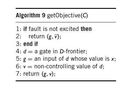
41 PODEM getobjective
42 PODEM Backtrace
43 PODEM Example Consider fault f/0: Test vector 1X0
44 PODEM Example Consider fault b/0: Fault b/0 is undetectable.
45 PODEM Example Consider fault g/1: Fault g/1 is undetectable.
46 FAN PODEM can still make an excessive number of decisions. FAN (Fanout-Oriented TG) algorithm improves PODEM by reducing the number of decision points. FAN identifies headlines in the circuit, which are the output signals of fanout-free regions -> any value assignment on the headline can always be justified by its fanin cone. Backtrace function stops at PI (as in PODEM) or at headlines, thus reducing the number of decision points.
47 FAN - Example Consider objective z = 1. PODEM: a=1, c=1, d=1, e=1, f=1 FAN: x=1, y=1
48 FAN Multiple Objectives FAN considers simultaneously multiple objectives. Justify k=0 Selecting b=0 causes a conflict later with objective m=1
49 Logic Implications Logic implications capture the effect of assigning logic values on other gates in order to make better decisions. Example: They can be divided into Static logic implications Dynamic logic implications
50 Static Logic Implications Direct implications Example, implication of logic value f = 1.
51 Static Logic Implications Indirect implications Can be computed by performing logic simulation on the current set of logic implications. Example, implication of logic value f = 1.
52 Static Logic Implications Extended backward implications Can be computed by performing logic simulation on the current set of logic implications. Example, implication of logic value f = 1.
53 Dynamic Logic Implications Static logic implications are computed once for the entire circuit, dynamic implications are performed during the ATPG process. Example, implication of logic value for z = 0 by c = 1. d=0 -> {a=0, b=0} e=0 -> {b=0} Dynamic implication for z = 0 by c = 1 -> {b=0}
54 Dynamic Logic Implications Dynamic logic implications can be used also for signals with fault-effect. Example, fault signal is on node b. In order to propagate fault signal to PO z, necessary condition is f=1.
55 Test Generation for Sequential Circuits One test vector may be insufficient to detect the target fault since the exication and propagation conditions may necessitate some of the flip-flop values. General model of sequential circuit:
56 Time Frame Expansion Method for transforming sequential circuit into combintional circuit over several time frames (iterative logic array). Target fault is present in every time frame.
57 5-Valued Algebra is Insufficient Consider the target fault b/0. Values a=1/0 or a=1/1 propagates the fault signal over the AND gate. This can be written as a=1/x.
58 5-Valued Algebra is Insufficient Consider the target fault b/1. Values a=1/1 or a=0/1 propagates the fault signal over the AND gate. This can be written as a=x/1. Additional values are therefore: 1/X, 0/X, X/1, X/0, all together 9 values (9-Valued Algebra)
59 Gated Clocks Gated clocks are used for power saving. Tranformation are used to ease ATPG process.
60 Multiple Clocks Multiple clocks benefit performance and power as circuit blocks are partitioned to different clock domains. Example of transformation:
61 Other issues in Deterministic TPG Untestable fault identification Multiple-line conflict analysis Genetic algorithms Testing for bridging and delay faults Testing of acyclic sequential circuits Using testing for logic and power optimization
CPE 628 Chapter 4 Test Generation. Dr. Rhonda Kay Gaede UAH. CPE Introduction Conceptual View. UAH Chapter 4
 Chapter 4 Test Generation Dr. Rhonda Kay Gaede UAH 1 4.1 Introduction Conceptual View Generate an input vector that can the - circuit from the one Page 2 1 4.1 Introduction Simple Illustration Consider
l Some materials from various sources! n Current course textbook! Soma 1! Soma 3!
 Ackwledgements! Test generation algorithms! Mani Soma! l Some materials from various sources! n r. Phil Nigh, IBM! n Principles of Testing Electronic Systems by S. Mourad & Y. Zorian! n Essentials of Electronic
VLSI Test Technology and Reliability (ET4076)
") VLSI Test Technology and Reliability (ET476) Lecture 5 Combinational Circuit Test Generation (Chapter 7) Said Hamdioui Computer Engineering Lab elft University of Technology 29-2 Learning aims of today
VLSI Test Technology and Reliability (ET476) Lecture 5 Combinational Circuit Test Generation (Chapter 7) Said Hamdioui Computer Engineering Lab elft University of Technology 29-2 Learning aims of today
VLSI System Testing. Outline
 ECE 538 VLSI System Testing Krish Chakrabarty Test Generation: 2 ECE 538 Krish Chakrabarty Outline Problem with -Algorithm POEM FAN Fault-independent ATPG Critical path tracing Random test generation Redundancy
Origins of Stuck-Faults. Combinational Automatic Test-Pattern Generation (ATPG) Basics. Functional vs. Structural ATPG.
 Basics. Functional vs. Structural ATPG.") Combinational Automatic Test-Pattern Generation (ATPG) Basics Algorithms and representations Structural vs functional test efinitions Search spaces Completeness Algebras Types of Algorithms Origins of
Combinational Automatic Test-Pattern Generation (ATPG) Basics Algorithms and representations Structural vs functional test efinitions Search spaces Completeness Algebras Types of Algorithms Origins of
Pinaki Mazumder. Digital Testing 1 PODEM. PODEM Algorithm. PODEM Flow Chart
 POEM Algorithm POEM IBM introduced semiconductor RAM memory into its mainframes late 970 s Memory had error correction and translation circuits improved reliability -ALG unable to test these circuits!
Advanced Digital Logic Design EECS 303
 Advanced igital Logic esign EECS 33 http://ziyang.eecs.northwestern.edu/eecs33/ Teacher: Robert ick Office: L477 Tech Email: dickrp@northwestern.edu Phone: 847 467 2298 Outline. 2. 2 Robert ick Advanced
UMBC. space and introduced backtrace. Fujiwara s FAN efficiently constrained the backtrace to speed up search and further limited the search space.
 ATPG Algorithms Characteristics of the three main algorithms: Roth s -Algorithm (-ALG) defined the calculus and algorithms for ATPG using -cubes. Goel s POEM used path propagation constraints to limit
Contents 1 Basic of Test and Role of HDLs 2 Verilog HDL for Design and Test
 1 Basic of Test and Role of HDLs... 1.1 Design and Test... 1.1.1 RTL Design Process... 1.1.2 Postmanufacturing Test... 1.2 Test Concerns... 1.2.1 Test Methods... 1.2.2 Testability Methods... 1.2.3 Testing
IMPLEMENTATION OF AN ATPG USING PODEM ALGORITHM
 IMPLEMENTATION OF AN ATPG USING PODEM ALGORITHM SACHIN DHINGRA ELEC 7250: VLSI testing OBJECTIVE: Write a test pattern generation program using the PODEM algorithm. ABSTRACT: PODEM (Path-Oriented Decision
Fault Simulation. Problem and Motivation
 Fault Simulation Problem and Motivation Fault Simulation Problem: Given A circuit A sequence of test vectors A fault model Determine Fault coverage Fraction (or percentage) of modeled faults detected by
Sequential Circuit Testing 3
 Sequential Circuit Testing 3 Recap: Approaches State table analysis Machine identification (checking sequence) method Time-frame expansion Misc. Issues Controlling and observing internal states of a sequential
Page 1. Outline. A Good Reference and a Caveat. Testing. ECE 254 / CPS 225 Fault Tolerant and Testable Computing Systems. Testing and Design for Test
 Page Outline ECE 254 / CPS 225 Fault Tolerant and Testable Computing Systems Testing and Design for Test Copyright 24 Daniel J. Sorin Duke University Introduction and Terminology Test Generation for Single
12. Use of Test Generation Algorithms and Emulation
 12. Use of Test Generation Algorithms and Emulation 1 12. Use of Test Generation Algorithms and Emulation Jacob Abraham Department of Electrical and Computer Engineering The University of Texas at Austin
Department of Electrical and Computer Engineering University of Wisconsin Madison. Fall Midterm Examination CLOSED BOOK
 Department of Electrical and Computer Engineering University of Wisconsin Madison ECE 553: Testing and Testable Design of Digital Systems Fall 2013-2014 Midterm Examination CLOSED BOOK Kewal K. Saluja
Test Generation for Asynchronous Sequential Digital Circuits
 Test Generation for Asynchronous Sequential Digital Circuits Roland Dobai Institute of Informatics Slovak Academy of Sciences Dúbravská cesta 9, 845 07 Bratislava, Slovakia roland.dobai@savba.sk Abstract
Overview ECE 753: FAULT-TOLERANT COMPUTING 1/23/2014. Recap. Introduction. Introduction (contd.) Introduction (contd.)
 Introduction (contd.)") ECE 753: FAULT-TOLERANT COMPUTING Kewal K.Saluja Department of Electrical and Computer Engineering Test Generation and Fault Simulation Lectures Set 3 Overview Introduction Basics of testing Complexity
ECE 753: FAULT-TOLERANT COMPUTING Kewal K.Saluja Department of Electrical and Computer Engineering Test Generation and Fault Simulation Lectures Set 3 Overview Introduction Basics of testing Complexity
Testing Digital Systems I
 Testing Digital Systems I Lecture 6: Fault Simulation Instructor: M. Tahoori Copyright 2, M. Tahoori TDS I: Lecture 6 Definition Fault Simulator A program that models a design with fault present Inputs:
Sequential Circuit Test Generation Using Decision Diagram Models
 Sequential Circuit Test Generation Using Decision Diagram Models Jaan Raik, Raimund Ubar Department of Computer Engineering Tallinn Technical University, Estonia Abstract A novel approach to testing sequential
Design and Synthesis for Test
 TDTS 80 Lecture 6 Design and Synthesis for Test Zebo Peng Embedded Systems Laboratory IDA, Linköping University Testing and its Current Practice To meet user s quality requirements. Testing aims at the
Compaction mechanism to reduce test pattern counts and segmented delay fault testing for path delay faults
 University of Iowa Iowa Research Online Theses and Dissertations Spring 2013 Compaction mechanism to reduce test pattern counts and segmented delay fault testing for path delay faults Sharada Jha University
Fault-Tolerant Computing
 Fault-Tolerant Computing Dealing with Low-Level Impairments Slide 1 About This Presentation This presentation has been prepared for the graduate course ECE 257A (Fault-Tolerant Computing) by Behrooz Parhami,
VLSI Test Technology and Reliability (ET4076)
") VLSI Test Technology and Reliability (ET4076) Lecture 4(part 2) Testability Measurements (Chapter 6) Said Hamdioui Computer Engineering Lab Delft University of Technology 2009-2010 1 Previous lecture What
VLSI Test Technology and Reliability (ET4076) Lecture 4(part 2) Testability Measurements (Chapter 6) Said Hamdioui Computer Engineering Lab Delft University of Technology 2009-2010 1 Previous lecture What
VLSI Test Technology and Reliability (ET4076)
") VLSI Test Technology and Reliability (ET4076) Lecture 8 (1) Delay Test (Chapter 12) Said Hamdioui Computer Engineering Lab Delft University of Technology 2009-2010 1 Learning aims Define a path delay fault
VLSI Test Technology and Reliability (ET4076) Lecture 8 (1) Delay Test (Chapter 12) Said Hamdioui Computer Engineering Lab Delft University of Technology 2009-2010 1 Learning aims Define a path delay fault
Advanced VLSI Design Prof. Virendra K. Singh Department of Electrical Engineering Indian Institute of Technology Bombay
 Advanced VLSI Design Prof. Virendra K. Singh Department of Electrical Engineering Indian Institute of Technology Bombay Lecture 40 VLSI Design Verification: An Introduction Hello. Welcome to the advance
Chapter 9. Design for Testability
 Chapter 9 Design for Testability Testability CUT = Circuit Under Test A design property that allows: cost-effective development of tests to be applied to the CUT determining the status of the CUT (normal
Chapter 1 Introduction
 Chapter 1 Introduction The advent of synthesis systems for Very Large Scale Integrated Circuits (VLSI) and automated design environments for Application Specific Integrated Circuits (ASIC) have allowed
ECE 156B Fault Model and Fault Simulation
 ECE 156B Fault Model and Fault Simulation Lecture 6 ECE 156B 1 What is a fault A fault is a hypothesis of what may go wrong in the manufacturing process In fact, a fault model is not trying to model the
Digital VLSI Testing Prof. Santanu Chattopadhyay Department of Electronics and EC Engineering India Institute of Technology, Kharagpur.
 Digital VLSI Testing Prof. Santanu Chattopadhyay Department of Electronics and EC Engineering India Institute of Technology, Kharagpur Lecture 05 DFT Next we will look into the topic design for testability,
REDI: An Efficient Fault Oriented Procedure to Identify Redundant Faults in Combinational Logic Circuits *
 REDI: An Efficient Fault Oriented Procedure to Identify Redundant Faults in Combinational Logic Circuits * Chen Wang, Irith Pomeranz and Sudhakar M. Reddy Electrical and Computer Engineering Department
SAT-BASED ATPG FOR DIGITAL INTEGRATED CIRCUITS BASED ON MULTIPLE OBSERVATIONS
 SAT-BASED ATPG FOR DIGITAL INTEGRATED CIRCUITS BASED ON MULTIPLE OBSERVATIONS SAT-BASED ATPG FOR DIGITAL INTEGRATED CIRCUITS BASED ON MULTIPLE OBSERVATIONS BY DAVID WING YIN LEUNG, B. ENG. & MGT. (COMPUTER)
An Efficient Method for Multiple Fault Diagnosis
 An Efficient Method for Multiple Fault Diagnosis Khushboo Sheth Department of Electrical and Computer Engineering Auburn University, Auburn, AL Abstract: In this paper, failing circuits are analyzed and
VLSI Testing. Lecture Fall 2003
 VLSI Testing Lecture 25 8-322 Fall 23 Announcement Homework 9 is due next Thursday (/2) Exam II is on Tuesday (/8) in class Review Session: When: Next Monday (/7) afternoon, 4pm 6pm Where: B3, HH 2 Outline
VLSI System Testing. Fault Simulation
 ECE 538 VLSI System Testing Krish Chakrabarty Fault Simulation ECE 538 Krish Chakrabarty Fault Simulation Problem and motivation Fault simulation algorithms Serial Parallel Deductive Concurrent Random
Metodologie di progetto HW Il test di circuiti digitali
 Metodologie di progetto HW Il test di circuiti digitali Introduzione Versione del 9/4/8 Metodologie di progetto HW Il test di circuiti digitali Introduction VLSI Realization Process Customer s need Determine
On Using Machine Learning for Logic BIST
 On Using Machine Learning for Logic BIST Christophe FAGOT Patrick GIRARD Christian LANDRAULT Laboratoire d Informatique de Robotique et de Microélectronique de Montpellier, UMR 5506 UNIVERSITE MONTPELLIER
Metodologie di progetto HW Il test di circuiti digitali
 Metodologie di progetto HW Il test di circuiti digitali Introduzione Versione del 9/4/8 Metodologie di progetto HW Il test di circuiti digitali Introduction Pag. 2 VLSI Realization Process Customer s need
An Efficient Test Relaxation Technique for Synchronous Sequential Circuits
 An Efficient Test Relaxation Technique for Synchronous Sequential Circuits Aiman El-Maleh and Khaled Al-Utaibi King Fahd University of Petroleum and Minerals Dhahran 326, Saudi Arabia emails:{aimane, alutaibi}@ccse.kfupm.edu.sa
1488 IEEE TRANSACTIONS ON COMPUTER-AIDED DESIGN OF INTEGRATED CIRCUITS AND SYSTEMS, VOL. 16, NO. 12, DECEMBER 1997
 1488 IEEE TRANSACTIONS ON COMPUTER-AIDED DESIGN OF INTEGRATED CIRCUITS AND SYSTEMS, VOL. 16, NO. 12, DECEMBER 1997 Nonscan Design-for-Testability Techniques Using RT-Level Design Information Sujit Dey,
Lecture 7 Fault Simulation
 Lecture 7 Fault Simulation Problem and motivation Fault simulation algorithms Serial Parallel Deductive Concurrent Random Fault Sampling Summary Copyright 2, Agrawal & Bushnell VLSI Test: Lecture 7 Problem
VLSI System Testing. Introduction
 ECE 538 VLSI System Testing Krish Chakraarty Test Generation: Part ECE 538 Krish Chakraarty Introduction Classification of test generation methods Fault tale analysis Boolean difference method Propagation,
Very Large Scale Integration (VLSI)
") Very Large Scale Integration (VLSI) Lecture 10 Dr. Ahmed H. Madian Ah_madian@hotmail.com Dr. Ahmed H. Madian-VLSI 1 Content Manufacturing Defects Wafer defects Chip defects Board defects system defects
Very Large Scale Integration (VLSI) Lecture 10 Dr. Ahmed H. Madian Ah_madian@hotmail.com Dr. Ahmed H. Madian-VLSI 1 Content Manufacturing Defects Wafer defects Chip defects Board defects system defects
Circuit versus CNF Reasoning for Equivalence Checking
 Circuit versus CNF Reasoning for Equivalence Checking Armin Biere Institute for Formal Models and Verification Johannes Kepler University Linz, Austria Equivalence Checking Workshop 25 Madonna di Campiglio,
Functional extension of structural logic optimization techniques
 Functional extension of structural logic optimization techniques J. A. Espejo, L. Entrena, E. San Millán, E. Olías Universidad Carlos III de Madrid # e-mail: { ppespejo, entrena, quique, olias}@ing.uc3m.es
HIGH QUALITY COMPACT DELAY TEST GENERATION. A Dissertation ZHENG WANG
 HIGH QUALITY COMPACT DELAY TEST GENERATION A Dissertation by ZHENG WANG Submitted to the Office of Graduate Studies of Texas A&M University in partial fulfillment of the requirements for the degree of
Digital Integrated Circuits
 Digital Integrated Circuits Lecture Jaeyong Chung System-on-Chips (SoC) Laboratory Incheon National University Design/manufacture Process Chung EPC655 2 Design/manufacture Process Chung EPC655 3 Layout
6 DESIGN FOR TESTABILITY I: FROM FULL SCAN TO PARTIAL SCAN
 94 Advances in Microelectronics 6 DESIGN FOR TESTABILITY I: FROM FULL SCAN TO PARTIAL SCAN Chia Yee Ooi 6.1 CONTEXT It is important to check whether the manufactured circuit has physical defects or not.
Special ATPG to Correlate Test Patterns for Low-Overhead Mixed-Mode BIST
 Special ATPG to Correlate Test Patterns for Low-Overhead Mixed-Mode BIST Madhavi Karkala Nur A. Touba Hans-Joachim Wunderlich Computer Engineering Research Center Computer Architecture Lab Dept. of Electrical
ABC basics (compilation from different articles)
") 1. AIG construction 2. AIG optimization 3. Technology mapping ABC basics (compilation from different articles) 1. BACKGROUND An And-Inverter Graph (AIG) is a directed acyclic graph (DAG), in which a node
1. AIG construction 2. AIG optimization 3. Technology mapping ABC basics (compilation from different articles) 1. BACKGROUND An And-Inverter Graph (AIG) is a directed acyclic graph (DAG), in which a node
Collapsing for Multiple Output Circuits. Diagnostic and Detection Fault. Raja K. K. R. Sandireddy. Dept. Of Electrical and Computer Engineering,
 Diagnostic and Detection Fault Collapsing for Multiple Output Circuits Raja K. K. R. Sandireddy Dept. Of Electrical and Computer Engineering, Auburn University, Auburn AL-36849 USA Outline Introduction
Driving Toward Higher I DDQ Test Quality for Sequential Circuits: A Generalized Fault Model and Its ATPG
 Driving Toward Higher I DDQ Test Quality for Sequential Circuits: A Generalized Fault Model and Its ATPG Hisashi Kondo Kwang-Ting Cheng y Kawasaki Steel Corp., LSI Division Electrical and Computer Engineering
VLSI Testing. Virendra Singh. Bangalore E0 286: Test & Verification of SoC Design Lecture - 7. Jan 27,
 VLSI Testing Fault Simulation Virendra Singh Indian Institute t of Science Bangalore virendra@computer.org E 286: Test & Verification of SoC Design Lecture - 7 Jan 27, 2 E-286@SERC Fault Simulation Jan
Upper Bounding Fault Coverage by Structural Analysis and Signal Monitoring
 Upper Bounding Fault Coverage by Structural Analysis and Signal Monitoring Abstract A new algorithm for determining stuck faults in combinational circuits that cannot be detected by a given input sequence
Faults, Testing & Test Generation
 Faults, Testing & Test Generation Smith Text: Chapter 14.1,14.3, 14.4 Mentor Graphics/Tessent: Scan and ATPG Process Guide ATPG and Failure Diagnosis Tools Reference Manual (access via mgcdocs ) ASIC Design
Net Diagnosis Using Stuck-at and Transition Fault Models. Lixing Zhao
 Net Diagnosis Using Stuck-at and Transition Fault Models by Lixing Zhao A thesis submitted to the Graduate Faculty of Auburn University in partial fulfillment of the requirements for the Degree of Master
Faults. Abstract. 1. Introduction. * Nur A. Touba is now with the Department of Electrical and Computer Engineering, University of Texas, Austin, TX
 s Abstract While previous research has focused on deterministic testing of bridging faults, this paper studies pseudo-random testing of bridging faults and describes a means for achieving high fault coverage
CRITICAL PATH TRACING - AN ALTERNATIVE TO FAULT SIMULATION
 CRITICAL PATH TRACING - AN ALTERNATIVE TO FAULT SIMULATION M. Abramovici P. R. Menon D. T. Miller Bell Laboratories Naperville, Illinois 6566 ABSTRACT We present an alternative to fault simulation, referred
Independence Fault Collapsing and Concurrent Test Generation
 Independence Fault Collapsing and Concurrent Test Generation Except where reference is made to the work of others, the work described in this thesis is my own or was done in collaboration with my advisory
LOGIC SYNTHESIS AND VERIFICATION ALGORITHMS. Gary D. Hachtel University of Colorado. Fabio Somenzi University of Colorado.
 LOGIC SYNTHESIS AND VERIFICATION ALGORITHMS by Gary D. Hachtel University of Colorado Fabio Somenzi University of Colorado Springer Contents I Introduction 1 1 Introduction 5 1.1 VLSI: Opportunity and
CMOS Testing: Part 1. Outline
 CMOS Testing: Part 1 Introduction Fault models Stuck-line (single and multiple) Bridging Stuck-open Test pattern generation Combinational circuit test generation Sequential circuit test generation ECE
SIDDHARTH INSTITUTE OF ENGINEERING AND TECHNOLOGY :: PUTTUR (AUTONOMOUS) Siddharth Nagar, Narayanavanam Road QUESTION BANK
 Siddharth Nagar, Narayanavanam Road QUESTION BANK") SIDDHARTH INSTITUTE OF ENGINEERING AND TECHNOLOGY :: PUTTUR (AUTONOMOUS) Siddharth Nagar, Narayanavanam Road 517583 QUESTION BANK Subject with Code : Digital system design(16ec3801) Course & Branch: M.Tech
SIDDHARTH INSTITUTE OF ENGINEERING AND TECHNOLOGY :: PUTTUR (AUTONOMOUS) Siddharth Nagar, Narayanavanam Road 517583 QUESTION BANK Subject with Code : Digital system design(16ec3801) Course & Branch: M.Tech
Mentor Graphics Tools for DFT. DFTAdvisor, FastScan and FlexTest
 Mentor Graphics Tools for DFT DFTAdvisor, FastScan and FlexTest 1 DFT Advisor Synthesis tool capable of doing DRC, Scan Insertion and Test point Synthesis Creates a do file and a test procedure file after
Techniques for Enhancing Test and Diagnosis of Digital Circuits
 Techniques for Enhancing Test and Diagnosis of Digital Circuits Sarvesh Pradeep Prabhu Dissertation submitted to the Faculty of the Virginia Polytechnic Institute and State University in partial fulfillment
A Parallel Implementation of Fault Simulation on a Cluster of. Workstations
 A Parallel Implementation of Fault Simulation on a Cluster of Workstations Except where reference is made to the work of others, the work described in this thesis is my own or was done in collaboration
Design Verification and Test of Digital VLSI Circuits NPTEL Video Course. Module-VIII Lecture-I Fault Simulation
 Design Verification and Test of Digital VLSI Circuits NPTEL Video Course Module-VIII Lecture-I Fault Simulation Introduction to Test Pattern Generation The procedure to generate a test pattern for a given
Digital VLSI Testing. Week 1 Assignment Solution
 Digital VLSI Testing Week 1 Assignment Solution Q1. Primary objective of testing is to guarantee (A) Fault-free products (B) Detection of design error (C) Reduction of product cost (D) All of these Ans:
VLSI Testing. Fault Simulation. Virendra Singh. Indian Institute of Science Bangalore
 VLSI Testing Fault Simulation Virendra Singh Indian Institute of Science Bangalore virendra@computer.org E0 286: Test & Verification of SoC Design Lecture - 4 Jan 25, 2008 E0-286@SERC 1 Fault Model - Summary
Focus On Structural Test: AC Scan
 Focus On Structural Test: AC Scan Alfred L. Crouch Chief Scientist Inovys Corporation al.crouch@inovys.com The DFT Equation The Problem What is Driving Modern Test Technology? 300mm Wafers Volume Silicon/Test
Combinational Equivalence Checking
 Combinational Equivalence Checking Virendra Singh Associate Professor Computer Architecture and Dependable Systems Lab. Dept. of Electrical Engineering Indian Institute of Technology Bombay viren@ee.iitb.ac.in
Digital System Test and Testable Design
 Digital System Test and Testable Design wwwwwwwwwwww Zainalabedin Navabi Digital System Test and Testable Design Using HDL Models and Architectures Zainalabedin Navabi Worcester Polytechnic Institute Department
HARDWARE EMULATION OF SEQUENTIAL ATPG-BASED BOUNDED MODEL CHECKING GREGORY FICK FORD. Submitted in partial fulfilment of the requirements
 HARDWARE EMULATION OF SEQUENTIAL ATPG-BASED BOUNDED MODEL CHECKING BY GREGORY FICK FORD Submitted in partial fulfilment of the requirements for the degree of Master of Science Thesis Advisor: Dr. Daniel
EECS 219C: Formal Methods Boolean Satisfiability Solving. Sanjit A. Seshia EECS, UC Berkeley
 EECS 219C: Formal Methods Boolean Satisfiability Solving Sanjit A. Seshia EECS, UC Berkeley The Boolean Satisfiability Problem (SAT) Given: A Boolean formula F(x 1, x 2, x 3,, x n ) Can F evaluate to 1
Bit-Fixing in Pseudorandom Sequences for Scan BIST
 IEEE TRANSACTIONS ON COMPUTER-AIDED DESIGN OF INTEGRATED CIRCUITS AND SYSTEMS, VOL. 20, NO. 4, APRIL 2001 545 Bit-Fixing in Pseudorandom Sequences for Scan BIST Nur A. Touba, Member, IEEE, and Edward J.
ATPG for Faults Analysis in VLSI Circuits Using Immune Genetic Algorithm
 ATPG for Faults Analysis in VLSI Circuits Using Immune Genetic Algorithm P.K.Chakrabarty 1, S.N.Patnaik 2 1Professor, Department of CSE., IT,BHU, India 2Asst.Professor, ECE Department, DRIEMS, Cuttack,
Transition Faults and Transition Path Delay Faults: Test Generation, Path Selection, and Built-In Generation of Functional Broadside Tests
 Purdue University Purdue e-pubs Open Access Dissertations Theses and Dissertations Fall 2013 Transition Faults and Transition Path Delay Faults: Test Generation, Path Selection, and Built-In Generation
On Test Generation by Input Cube Avoidance
 On Test Generation by Input Cube Avoidance Irith Pomeranz 1 and Sudhakar M. Reddy 2 School of Electrical & Computer Eng. Electrical & Computer Eng. Dept. Purdue University University of Iowa W. Lafayette,
VLSI Test Technology and Reliability (ET4076)
") VLSI Test Technology and Reliability (ET4076) Lecture 2 (p2) Fault Modeling (Chapter 4) Said Hamdioui Computer Engineering Lab Delft University of Technology 2009-2010 1 Previous lecture What are the different
VLSI Test Technology and Reliability (ET4076) Lecture 2 (p2) Fault Modeling (Chapter 4) Said Hamdioui Computer Engineering Lab Delft University of Technology 2009-2010 1 Previous lecture What are the different
Additional Slides to De Micheli Book
 Additional Slides to De Micheli Book Sungho Kang Yonsei University Design Style - Decomposition 08 3$9 0 Behavioral Synthesis Resource allocation; Pipelining; Control flow parallelization; Communicating
Marrying Formal Methods With Simulation-Based Verification Function Verification Research at UCSB. Tim Cheng & Li-C. Wang UC-Santa Barbara
 Marrying Formal Methods With Simulation-Based Verification Function Verification Research at UCSB Tim Cheng & Li-C. Wang UC-Santa Barbara 1 Outline Current Issues in Functional Verification Functional
Monte Carlo Methods; Combinatorial Search
 Monte Carlo Methods; Combinatorial Search Parallel and Distributed Computing Department of Computer Science and Engineering (DEI) Instituto Superior Técnico November 22, 2012 CPD (DEI / IST) Parallel and
Design for Testability
 Design for Testability Sungho Kang Yonsei University Outline Introduction Testability Measure Design for Testability Ad-Hoc Testable Design Conclusion 2 Merging Design and Test Design and Test become closer
Heuristic Minimization of Boolean Relations Using Testing Techniques
 Heuristic Minimization of Boolean Relations Using Testing Techniques Abhijit Ghosh Srinivas Devadas A. Richard Newton Department of Electrical Engineering and Coniputer Sciences University of California,
Experimental Study Of Fault Cones And Fault Aliasing
 Portland State University PDXScholar Dissertations and Theses Dissertations and Theses 1-1-2012 Experimental Study Of Fault Cones And Fault Aliasing Vedanth Bilagi Portland State University Let us know
PROR compaction scheme for larger circuits and longer vectors with deterministic ATPG
 PROR compaction scheme for larger circuits and longer vectors with deterministic ATPG Suresh k Devanathan Michael L Bushnell Abstract Reverse order restoration ROR techniques have found great use in sequential
Upper Bounding Fault Coverage by Structural Analysis and Signal Monitoring
 Upper Bounding Fault Coverage by Structural Analysis and Signal Monitoring Vishwani D. Agrawal Auburn Univerity, Dept. of ECE Soumitra Bose and Vijay Gangaram Intel Corporation, Design Technology Auburn,
PART B. 3. Minimize the following function using K-map and also verify through tabulation method. F (A, B, C, D) = +d (0, 3, 6, 10).
 = +d (0, 3, 6, 10).") II B. Tech II Semester Regular Examinations, May/June 2015 SWITCHING THEORY AND LOGIC DESIGN (Com. to EEE, ECE, ECC, EIE.) Time: 3 hours Max. Marks: 70 Note: 1. Question Paper consists of two parts (Part-A
II B. Tech II Semester Regular Examinations, May/June 2015 SWITCHING THEORY AND LOGIC DESIGN (Com. to EEE, ECE, ECC, EIE.) Time: 3 hours Max. Marks: 70 Note: 1. Question Paper consists of two parts (Part-A
Lecture 3 - Fault Simulation
 Lecture 3 - Fault Simulation Fault simulation Algorithms Serial Parallel Deductive Random Fault Sampling Problem and Motivation Fault simulation Problem: Given A circuit A sequence of test vectors A fault
Combinatorial Search; Monte Carlo Methods
 Combinatorial Search; Monte Carlo Methods Parallel and Distributed Computing Department of Computer Science and Engineering (DEI) Instituto Superior Técnico May 02, 2016 CPD (DEI / IST) Parallel and Distributed
II/IV B.Tech (Regular/Supplementary) DEGREE EXAMINATION. Answer ONE question from each unit.
 DEGREE EXAMINATION. Answer ONE question from each unit.") Hall Ticket Number: 14CS IT303 November, 2017 Third Semester Time: Three Hours Answer Question No.1 compulsorily. II/IV B.Tech (Regular/Supplementary) DEGREE EXAMINATION Common for CSE & IT Digital Logic
Hall Ticket Number: 14CS IT303 November, 2017 Third Semester Time: Three Hours Answer Question No.1 compulsorily. II/IV B.Tech (Regular/Supplementary) DEGREE EXAMINATION Common for CSE & IT Digital Logic
Static Compaction Techniques to Control Scan Vector Power Dissipation
 Static Compaction Techniques to Control Scan Vector Power Dissipation Ranganathan Sankaralingam, Rama Rao Oruganti, and Nur A. Touba Computer Engineering Research Center Department of Electrical and Computer
X(1) X. X(k) DFF PI1 FF PI2 PI3 PI1 FF PI2 PI3
 X. X(k) DFF PI1 FF PI2 PI3 PI1 FF PI2 PI3") Partial Scan Design Methods Based on Internally Balanced Structure Tomoya TAKASAKI Tomoo INOUE Hideo FUJIWARA Graduate School of Information Science, Nara Institute of Science and Technology 8916-5 Takayama-cho,
Partial Scan Design Methods Based on Internally Balanced Structure Tomoya TAKASAKI Tomoo INOUE Hideo FUJIWARA Graduate School of Information Science, Nara Institute of Science and Technology 8916-5 Takayama-cho,
An Implicit Enumeration Algorithm to Generate
 IEEE TRANSACTIONS ON COMPUTERS, VOL. C-30, NO. 3, MARCH 1981 An Implicit Enumeration Algorithm to Generate Tests for Combinational Logic Circuits 215 PRABHAKAR GOEL Abstract-The D-algorithm (DALG) is shown
R10. II B. Tech I Semester, Supplementary Examinations, May
 SET - 1 1. a) Convert the following decimal numbers into an equivalent binary numbers. i) 53.625 ii) 4097.188 iii) 167 iv) 0.4475 b) Add the following numbers using 2 s complement method. i) -48 and +31
SPLIT CIRCUIT MODEL FOR TEST GENERATION
 SPLT CRCUT MODEL FOR TEST GENERATON Wu-Tung Cheng AT&T Engineering Research Center Princeton, NJ 854 Tel. (69) 639-2422 ABSTRACT Over the years, the D-algorithm has been successfully used to generate tests
Code No: R Set No. 1
 Code No: R059210504 Set No. 1 II B.Tech I Semester Supplementary Examinations, February 2007 DIGITAL LOGIC DESIGN ( Common to Computer Science & Engineering, Information Technology and Computer Science
Chapter 7. Logic Diagnosis. VLSI EE141 Test Principles and Architectures Ch. 7 - Logic Diagnosis - P. 1
 Chapter 7 Logic Diagnosis VLSI EE4 Test Principles and Architectures Ch. 7 - Logic Diagnosis - P. Outline Introduction Combinational Logic Diagnosis Scan Chain Diagnosis Logic BIST Diagnosis Conclusion
Deterministic BIST ABSTRACT. II. DBIST Schemes Based On Reseeding of PRPG (LFSR) I. INTRODUCTION
 I. INTRODUCTION") Deterministic BIST Amiri Amir Mohammad Ecole Polytechnique, Montreal, December 2004 ABSTRACT This paper studies some of the various techniques of DBIST. Normal BIST structures use a PRPG (LFSR) to randomly
Deterministic BIST Amiri Amir Mohammad Ecole Polytechnique, Montreal, December 2004 ABSTRACT This paper studies some of the various techniques of DBIST. Normal BIST structures use a PRPG (LFSR) to randomly
Digital System Design with SystemVerilog
 Digital System Design with SystemVerilog Mark Zwolinski AAddison-Wesley Upper Saddle River, NJ Boston Indianapolis San Francisco New York Toronto Montreal London Munich Paris Madrid Capetown Sydney Tokyo
At-Speed Scan Test with Low Switching Activity
 21 28th IEEE VLSI Test Symposium At-Speed Scan Test with Low Switching Activity Elham K. Moghaddam Department of ECE, University of Iowa, Iowa City, IA 52242 ekhayatm@engineering.uiowa.edu Janusz Rajski
Exploiting Arithmetic Built-In Self-Test Techniques for Path Delay Fault Testing
 Øystein Gjermundnes Exploiting Arithmetic Built-In Self-Test Techniques for Path Delay Fault Testing Thesis for the degree doktor ingeniør Trondheim, November 26 Norwegian University of Science and Technology