NX Advanced FEM (Version NX 5)
|
|
|
- Walter Lyons
- 6 years ago
- Views:
Transcription
1 NX Advanced FEM (Version NX 5) UGS Corp All rights reserved. UGS PLM Software
2 Aims There are 225 slides in this file, it is NOT the expectation that you show all of them to the prospect/customer The aim here is to provide a deck of slides that you can choose to pick and mix from to show a workflow or solution that is appropriate to your requirements These slides describe the Core functionality. I have skipped some icons/functions as they are only applicable for one of the add-on applications. These can be used as the build up for a presentation on one of the add-on applications like Laminates, Response Simulation, Thermal, Flow etc As these slides are all built to a consistent style, doing a pick and mix will still result in a clean looking presentation Please note that after the Solver Language Environment slides, everything is NX Nastran specific Please provide any enhancements or suggestions to Guy.Wills@Siemens.com ( ) Slides 2 6 are not intended for Public use 2
3 Slide Organisation (1) NX Advanced FEM File Organization Master Part Basic file structure Master Part Idealize and Multiple FEM s Material Property Library Multiple SIM s Physical Property Override Material Properties Multiple SIM s Physical Property & Thickness Override Multiple Solutions and subcase s Variations Idealize Part Part Idealize Part Uses of the Idealize part Model Interaction Simulation Navigator File View Simulation Navigator Easy Management Simulation Navigator Resource Bars Interaction RMB Over Screen Model Mirror Display Model Interaction Show Only Model Interaction Show Adjacent Idealize Part Idealize Idealize Part Defeature Geometry Idealize Part Partition Idealize Part Midsurface Idealize Part Subdivide Faces Idealize Part Additional Modelling Idealize Part Direct Modelling Idealize Part Material Properties Model Interaction Node Display Model Interaction Mesh Display Model Interaction Mesh Control Display Solver Language Environment Solver Language Environment NX Nastran Environment UI Based on Solver/Solution ANSYS Environment UI Based on Solver/Solution ABAQUS Environment UI Based on Solver/Solution Slides 2 6 are not intended for Public use 3
4 Slide Organisation (2) FEM Part FEM Part NX Advanced Simulation : CAE Topology NX CAE Topology Geometric Abstraction and Meshing NX CAE Topology NX CAE Topology Auto Heal NX CAE Topology Split Edge NX CAE Topology Split Face NX CAE Topology Merge Edge NX CAE Topology Merge Face NX CAE Topology Match Edge NX CAE Topology Collapse Edge NX CAE Topology Face Repair NX CAE Topology Reset NX CAE Topology Mesh Updates Physical Properties Mesh Collectors Node & Element Sets Mesh Append Mesh Import Mesh Connections Mesh Mating Mesh Connections Edge-Face Connection Mesh Connections Edge Contact Mesh Mesh Connections Surface Contact Mesh Meshing Mesh Points Datum Coordinate Systems Mesh Size Selection FEM Part (cont) Mesh Controls Meshing OD Mesh Meshing 1D Element Cross Sections Meshing 1D Mesh Meshing 1D Mesh Element Attributes Meshing 2D Dependant Mesh Meshing 2D Mapped Mesh Meshing 2D Mesh Meshing 2D Mesh Seeding for 3D Mesh Meshing 3D Swept Mesh Meshing Solid from Shell Mesh Meshing 3D Tetrahedral Mesh Meshing Node Create Meshing Node Between Nodes Meshing Node on Curve/Edge Meshing Node Translate Meshing Node Rotate Meshing Node Reflect Meshing Node Drag Meshing Node Align Meshing Node Displacement CSYS Meshing Node Re-Numbering Meshing Node Modify Coordinate Meshing Node Deletion Meshing Node & Element Information Meshing Node Displacement CSYS FEM Part (cont) Meshing Element Create Meshing Element Extrude Meshing Element Revolve Meshing Element Translate & Copy Meshing Element Copy & Project Meshing Element Copy & Reflect Meshing Shell Split Meshing Combine Tris Meshing Move Mode Meshing Element Re-label Meshing Element Connectivity Meshing Element Deletion Meshing Node & Element Information Meshing Mesh Unlock Model Checking Element Shape Model Checking Element Outlines Model Checking Duplicate Nodes Model Checking Element Normals Slides 2 6 are not intended for Public use 4
5 Slide Organisation (3) SIM Part Pre-Processing SIM Part Pre-Processing (cont) Modeling Objects Manager Constraints Slider Modeling Objects Contact Set Parameters Constraints Pinned Modeling Objects Strategy Parameters Constraints Cylindrical Modeling Objects Real Eigenvalue, Lanczos & Householder Constraints Roller Modeling Objects Forcing Frequencies Direct & Modal Constraints Symmetric Modeling Objects Time Step Constraints Anti-Symmetric Modeling Objects Structural Output Requests Constraints Velocity Modeling Objects Solution Parameters Constraints Acceleration Modeling Objects System Cells Constraints Automatic Coupling Surface to Surface Contact Constraints Manual Coupling Surface to Surface Glue Constraints Enforced Motion Location Loads Force Boundary Condition Symbol Display Controls Loads Bearing Physical Property Overrides Loads Torque Custom Units & Units Converter Loads Moment Unit Selection Loads Pressure Boundary Condition Magnitude Table Field Loads Hydrostatic Pressure Boundary Condition Magnitude Function Field Loads Gravity Solution Loads Centrifugal Solution Containers and Re-using Data Loads Constant Temperature Solution Subcase Management Loads Nodal Force Location Solution Attributes Constraints User Defined Solution Parameters Constraints Enforced Displacement Solution Comprehensive Check Constraints Fixed, Translation & Rotation Solution Report Before Solve Constraints Simply Supported Solution Solve the Active Solution Slides 2 6 are not intended for Public use 5
6 Slide Organisation (4) SIM Part Post-Processing NX Integrated Post Processing Results Selection Results Animation Results Post View Display Results Post View Color Bar Results Post View Edges & Faces Results Identify Results Annotation Markers Results Previous / Next Mode or Iteration Results Post Views & Templates Simulation Customer Defaults Customer Defaults General Customer Defaults Model Preparation Customer Defaults Mesh Display Customer Defaults Node & Element Display Customer Defaults Mesh Controls Customer Defaults Boundary Condition Display Customer Defaults Threshold Values Nastran Customer Defaults Meshing Customer Defaults Analysis Customer Defaults Post Processor Results Multiple Viewports Results Post View Overlay Plotting Paths Graph Style Graph Probing Graph Windowing Solution Report After Solve Export Visualisation Files Slides 2 6 are not intended for Public use 6
7 NX Advanced FEM File Organisation UGS Corp All rights reserved. UGS PLM Software

8 Basic file structure Simulation part FEM Part Benefits Working in a concurrent environment Efficient use of model and data reuse Efficient use of local memory not all files need to be loaded Idealize Part Master Part Note Write Access to Master Part is not required 8


9 9 Multiple Idealize and Multiple FEM s FEM1 FEM4 FEM2 FEM3 Benefits Multiple analyses for same CAD part Multiple representations for different analysis needs from same CAD part CAE user view Idealize Part Idealize Part CAD user view Master Part
10 Multiple SIM s Physical Property Override SIM1 Generic Steel (Inherited from Master Part) SIM2 AISI_STEEL_1008+HR FEM1 Idealize Part Master Part Benefits Quickly and easily explore effects of different materials What if and sensitivity studies 10


11 Multiple SIM s Properties & Material Override SIM1 Inherited Properties SIM2 Properties & Material Overrides FEM1 Master Part Idealize Part Benefits Quickly and easily explore effects of different materials, thicknesses, shell offsets etc What if and sensitivity studies 11
12 12 Multiple Solutions and Subcase s SIM1 FEM1 Solution 1 Solution 2 Subcase 1 Simulation Containers Benefits Quickly and easily explore effects of different loading conditions Efficient analysis in complex environments Boundary Conditions referenced from Simulation Container Idealize Part Subcase 1 Multiple Subcases Master Part Multiple Solutions
13 Variations Simulation Part Simulation Part FEM Part Additional external FE data FEM Part External FE data Master Part No Idealized part required No Idealized or Master Part required Benefits Quickly and easily include external FE data Flexible work flows work the way you want to work 13
14 Model Interaction UGS Corp All rights reserved. UGS PLM Software


15 15 Simulation Navigator File View Simulation Centric View Design Part Centric View Design Part Centric View with Unused Parts Hidden Simulation File View Simulation Centric View for the analysts Design Part Centric View for the inverted view Active File shown in Blue Optionally any unused and open parts can be hidden Easy to understand the file relationships Fast method of Switching active file Double Click Fast method to create new Simulation files

16 16 Simulation Navigator Easy Management Simulation Centric File View Active Solver Environment Mesh Out-of- Date Symbol Hide/Show of Polygon models and Meshes during selection Drag n Drop from Containers to Solution Containers to Organise related CAE Data
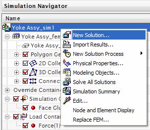


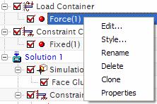
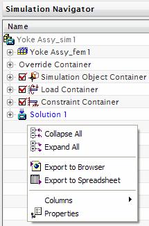
17 17 Simulation Navigator Easy Management RMB Operations Directly from Navigator


18 18 Simulation Navigator Resource Bars Resource Bars for Simulation Simulation Post Processing XY Functions


19 19 Simulation Navigator Resource Bars Roles Industry Specific Advanced & Essentials General Assembly Navigator Part Navigator History Internet Explorer On-Line Help


20 20 Interaction RMB Over Screen Model RMB Over Screen Entities enables fast access to functionality applicable to the highlighted item


21 21 Mirror Display Mirror Display is powerful for visualising Symmetric models Mirror Plane can be set anywhere Post View Settings work with the Mirror Display


22 22 Model Interaction Show Only Reduce the complexity of geometry on the screen Focus on a sub-set of the model Selection Methods Tangent Faces Adjacent Faces Fillet Faces Cylindrical Faces Sliver Faces Hide/Show from the Simulation Navigation Used during other commands to simply the screen Show Hide


23 23 Model Interaction Show Adjacent Show Adjacent to grow visible related geometry Selection Methods Tangent Faces Adjacent Faces Fillet Faces Cylindrical Faces Sliver Faces
 Medium")
24 24 Model Interaction Node Display Node Display options None (default) Dot Asterisk Color Element Display options Coarse (default) Medium Fine


25 25 Model Interaction Mesh Display Mesh Display By Collector By Mesh Mesh Display options Colour Edge Colour Shrink Percentage 2d Element Normals


26 26 Model Interaction Mesh Control Display Mesh Control Symbol display Size Shaded With Text Value
27 Solver Language Environment UGS Corp All rights reserved. UGS PLM Software

28 28 Solver Language Environment PLM XML definitions enable rapid change & addition of solver languages All Loads, Boundary Conditions, Element Types, and Solver Inputs reflect selected solution environment

29 29 Solver Language Environment (cont) Non-UGS Solver support Import of I-deas Universal file with CAE data only


30 30 NX Nastran Environment UI Based on Solver/Solution Selected at FEM part file creation Mesh creation Selected at Solution creation in SIM part Solution creation and editing Defines Sub-Case options Benefits User interface words are familiar Elements, Loads, Boundary Conditions etc are all in the words of the selected Solver


31 31 ANSYS Environment UI Based on Solver/Solution Selected at FEM part file creation Mesh creation Selected at Solution creation in SIM part Solution creation and editing Defines Sub-Case options Benefits User interface words are familiar Elements, Loads, Boundary Conditions etc are all in the words of the selected Solver


32 32 ABAQUS Environment UI Based on Solver/Solution Selected at FEM part file creation Mesh creation Selected at Solution creation in SIM part Solution creation and editing Defines Sub-Case options Benefits User interface words are familiar Elements, Loads, Boundary Conditions etc are all in the words of the selected Solver
33 Master Part UGS Corp All rights reserved. UGS PLM Software


34 34 Master Part Simulation Part Idealized part is NOT a requirement Full NX CAD modelling functionality is available for building models for CAE purposes FEM Part Master Part


35 35 Material Property Library Import from Material Property Library Metals Plastics Isotropic Orthotropic Anisotropic Fluids Assign to Parts Create new based on existing materials


36 36 Material Properties Constant Values Variable Values defined by a Table Units selection Adding new materials to the Library is documented in the on-line help
37 Idealize Part UGS Corp All rights reserved. UGS PLM Software
38 Idealize Part Simulation part FEM Part Idealize Part Master Part Uses of the Idealize part Read only Master Part Therefore can not change the Master Part geometry Vital in a Managed Environment What If exploration or studies based on the same Master Part Geometry Reduction or Abstraction Additional Geometry or Datums Benefits Support Concurrent Engineering Associativity to Master Model 38
39 39 Uses of the Idealize part Idealize Part Idealize Part Idealize Part Idealize Part Master Part What If exploration or studies based on the same Master Part Removing geometry By type and size Holes and Blends By selection Auto saved methods for updates Adding Additional Modelling features, holes, blends, chamfers, ribs, bosses etc Different materials from the Master Part
40 40 Uses of the Idealize part Idealize Part Idealize Part Idealize Part Idealize Part Idealize Part Idealize Part Master Part Geometry Reduction or Abstraction One or more significant geometry changes to the Master Part Symmetric, Asymmetric or Axisymmetric models Mid-Surface Partition or Surface Splitting Load/Restraint Application Local mesh control Mesh Mating condition common mesh across boundary
41 41 Uses of the Idealize part Idealize Part Idealize Part Idealize Part Master Part Additional Geometry Datums like Coordinate Systems Curves and points to place FEM entities Lumped Mass Rigid Elements


42 42 Idealize Part Idealize Removing Holes and Blends Based on their size Manual selection Idealize Part Idealize Part Idealize Part Idealize Part Master Part

43 43 Idealize Part Defeature Geometry Removing Geometry by Selection Method saved for Update replays Pick outermost face as seed Pick Region boundary faces Idealize Part Idealize Part Selected faces Master Part Resulting De-feature
 into multiple surface patches that share common edges Load/Restraint Application Local")

44 44 Idealize Part Partition Cutting part(s) into multiple volumes that share common faces Cutting part(s) into multiple surface patches that share common edges Load/Restraint Application Local mesh control Mesh Mating condition common mesh across boundary Associative or Non-Associative to model Idealize Part Idealize Part Idealize Part Idealize Part Idealize Part Idealize Part Master Part

45 45 Idealize Part Midsurface Automatic Midsurface generation Face Pair technique Offset technique Using another Sheet Body to define the Midsurface Proportional Thickness or Specific value Idealize Part Idealize Part Idealize Part Idealize Part Idealize Part Idealize Part Master Part

46 46 Idealize Part Subdivide Faces Subdividing Faces Intersection of Datum Planes Intersection of Faces Projected Curves and Edges Projected Line between 2 points Load/Restraint Application Local mesh control Idealize Part Idealize Part Idealize Part Idealize Part Idealize Part Idealize Part Master Part

47 47 Idealize Part Additional Modelling All modelling functionality is available Datums, curves, holes, blends, chamfers, ribs, bosses, surfaces, solids etc etc Idealize Part Idealize Part Idealize Part Idealize Part Master Part
 Editing parts with no")


48 Idealize Part Direct Modelling Direct Modelling (DMX) Editing parts with no CAD features Imported geometry Surrounding BREP updated Tangency maintained Surfaces Resized Fillets Surfaces Replaced Little End Moved Bolt Holes moved 48
 different from the Master Part What If studies of different")
49 49 Idealize Part Material Properties Override Material Master Part Material Set the Material Properties of the body(s) different from the Master Part What If studies of different materials
50 FEM Part UGS Corp All rights reserved. UGS PLM Software
51 51 FEM Part Simulation part Uses of the FEM part Geometry Abstraction CAE Topology FEM Part Model Organisation using Collectors Meshing Idealize Part Automatic Manual Mesh Connections Master Part Model Checking

52 52 NX Advanced Simulation : CAE Topology CAE Topology What is it? An abstracted layer of CAE specific topology with CAE specific modeling tools, over and above that provided by CAD Initially one polygon face is created for each CAD face What does it do? Automatically simplifies geometry by removing irregular and tiny features to allow effective CAE meshing Fully Manual through to a Fully Automatic process. Best practise is a mix of Manual and Automatic simplification Why is it valuable? Reduces the time to mesh and the number of elements generated (reducing solve time) while improving element quality and results accuracy

53 53 NX CAE Topology Geometric Abstraction and Meshing CAE Topology Design Geometry Realities

54 54 NX CAE Topology Issues


55 55 NX CAE Topology 0.02mm wide sliver

56 NX CAE Topology Issues 56


57 NX CAE Topology 57


58 58 NX CAE Topology Auto Heal Healing of CAE Topology Selected faces Complete model Auto calculation of Small Feature value Also removes sharp sliver like corners Before Heal After Heal


59 59 NX CAE Topology Split Edge Split an Edge To define separate Boundary Conditions along a Polygon edge Point Selection Control mesh density


60 60 NX CAE Topology Split Face Split Face Split a polygon face along a projected line Mesh control Boundary Condition control


61 61 NX CAE Topology Merge Edge Merge Edge Merges 2 polygon edges that share a vertex into one polygon edge Used to recover Split Edges


62 62 NX CAE Topology Merge Face Merge Face Merge two separate polygon faces into a single polygon face along a common polygon edge Commonly before and after an Auto Heal Before or After Meshing Used to remove data to get a better quality mesh


63 63 NX CAE Topology Match Edge Match one polygon edge to a second polygon edge Result is a single polygon edge Used to tidy up or repair poor quality geometry


64 64 NX CAE Topology Collapse Edge Collapses the selected polygon edge to a selected point on the edge Used to get manual control over how small edges are collapsed


65 65 NX CAE Topology Face Repair Create a new polygon face to fill a hole Repair a poor quality polygon face


66 66 NX CAE Topology Reset Resets the selected polygon geometry to it s original state ie one for one with the CAD surfaces Recover data for including in Mesh

67 67 NX CAE Topology Mesh Updates CAE Topology changes can be done before and after Meshes are applied After a change (like Merge Face) the Mesh is flagged out of date In the Simulation Navigator Mesh Update icon Note if multiple meshes exist, only the changed ones are flagged as out of date and updated Allows for multiple CAE Topology changes and one mesh update


68 68 Physical Properties Physical Property is Solver and Element dependant Family of Elements Material Reference Commonly referred to as PID Often used to identify different parts in an Assembly


69 69 Mesh Collectors Mesh Collectors are a method for multiple Meshes to reference the same Material, Physical Properties and Display Properties Organised by Element Family Element Type Physical Property (inc Material) Workflow Creation Options Prior to Meshing On-the-fly During Meshing Post Meshing

70 70 Mesh Collectors Model Management Drag n Drop item between collectors Mesh inherits the target Collector properties inc Physical, Material and Display Display control Benefits Hide/Show all Meshes in Collector Hide/Show Individual Meshes Model management Visible model organization Fast and easy to use for detail or global changes


71 71 Node and Element Sets Named Collection of Nodes or Elements Used for defining output for a solution FEM Based Sets can be used by any referencing SIM SIM Based Sets are only available within that SIM file


72 72 Mesh Append Mesh Append copies Mesh from one FEM file into the current FEM file Optional Prefix to Imported object Names Node, Element & PID number Start and Offsets


73 73 Mesh Import Import of a solver deck from an External file Units selection for the incoming data Append to existing files or Create New files


74 74 Mesh Connections Mesh Mating Mesh Mating Conditions aligns the mesh on Source and Target Glue Coincident condition 2 faces share same nodes Glue Non-Coincident condition Multi-Point Constraints (MPC s) to connect the meshes Free Coincident condition No mesh connection Auto Detection or Manual Selection of mating faces Search all possible pairs or only for identical pairs of faces Used to prepare mesh for Contact definition


75 75 Mesh Connections Edge-Face Connection Connection between a set of edges and a set of faces Contact Node drive Meshes in both sides if Match Meshes used Uses Rigid Links and MPC s to connect the meshes Glue Meshes Match Meshes


76 76 Mesh Connections Edge Contact Mesh Edge Based Contact definition Contact Nodes drive meshes on both sides Uses GAP elements to model Contact


77 77 Mesh Connections Surface Contact Mesh Surface Based Contact definition Surfaces are not auto Split or Partitioned Contact Nodes drive meshes on both sides Uses GAP elements to model Contact


78 78 Meshing Mesh Points Used to create specific location for a node, for example on an Edge or Face Point can Associative or Non- Associative to Geometry Mesh is associative to the Mesh Point Mesh Point location can be edited Used to create a location for a Load or Boundary Condition, spider for load transfer Mesh Point

79 79 Datum Coordinate Systems Datum Coordinate Systems Cartesian Cylindrical Spherical
80 80 Mesh Size Selection The Lightening symbol will suggest an Overall Element Size based on examination of the selected geometry User can set a value appropriate to their task Default settings for everything else will give a good mesh for most geometry
81 81 Mesh Size Selection Surface Mesh Size Variation Min less curvature refinement to follow geometry Max more curvature refinement to follow geometry Volume Mesh Size Variation Min elements remain approx constant in size throughout the body Max elements expand rapidly towards the center of the body Mesh Transition Gradually transitions the size of elements in the mesh from any defined local element sizes back to the global element size

82 82 Mesh Size Selection Small Feature tolerance defines size of geometry that will be abstracted Element size of 10mm & 10% setting will abstract out 1mm sized faces Merge Edges Removes the Polygon edge when angle between edges is less than Vertex Angle Mapped Mesh control of Fillets/Blends faces Filtered by Inside, Outside or Both Min & Max radius


83 83 Mesh Controls Mesh Controls Number on an Edge Size on an Edge Chordal Tolerance on an Edge Biasing on an Edge Size on a Face Managed by Mesh Controls Collector


84 84 Mesh Controls Size on Face Mesh Control Used to control Mesh distribution, quality, mating etc Meshes associative to Mesh Controls


85 Meshing OD Mesh 0D or Scalar Elements for Lumped or Distributed Mass Element Attributes vary according to the Solver Environment & Element Type 85


86 86 Meshing 1D Element Cross Sections Standard Cross Sections User Defined Properties Dialog to define and Manage Cross Sections 1D Element Attributes will Reference Stored Sections User Defined Sketch User Defined Solid Face


87 87 Meshing 1D Mesh Multiple options depending on the selection of Group 1 and 2 Group 2 Group 1 Along an edge, around a face, between curves or edges, point to curve/edge etc Element Attributes vary according to the Solver Environment & Element Type


88 88 Meshing 1D Mesh Element Attributes 1D Element Cross Sections 1D Elements reference a Physical Property Material Section(s) Element Attributes for Beams, Bars and Rods Beams & Bars require Orientation vector Inherited from Geometry Specific Values Bushes require Axis Definition Element Attributes vary according to the Solver Environment & Element Type


89 89 Meshing 2D Dependant Mesh Master & Target face selection Topologically Identical Faces Multiple Faces and Loops Coordinate System Selection Mesh Type Selection Free or Mapped New Mesh or Use Existing Mesh on Master Face Managed by 2D Collector Uses Contact Regions Flange Mating Symmetric Faces

 Mesh Controls")


90 Meshing 2D Mapped Mesh 3 or 4 Topological Sided Face (Single Loop) Mesh Controls automatically added if not pre-defined Can be used as Seed for 3D Meshing Element Attributes vary according to the Solver Environment & Element Type 90


91 91 Meshing 2D Mesh Creation of 2D Shell or Plate elements on selected faces Mesh will be also driven by Mesh Points Mating Conditions Contact Definitions Mesh Controls


92 92 Meshing 2D Mesh Seeding for 3D Mesh 2D Mesh can be used to Seed or define a 3D Mesh Turn OFF Export Mesh to Solver 2D Mesh does NOT get written to the solver Also does not appear in the SIM file


93 93 Meshing 3D Swept Mesh Preview of Mesh distribution along edges 3D Swept Mesh requires source face selection This face is meshed and swept through the volume Notice Mapped meshing around holes


94 94 Meshing 3D Swept Mesh Green 2D Seed Meshes to define 3D Swept Mesh Brown & Blue 3D Swept Meshes 2D Mesh the Seed faces to control mesh type and distribution 2D Mesh Turn OFF Export Mesh to Solver then this mesh is not written to the solver input deck 3D Swept Mesh starts with these Seed meshes


95 95 Meshing Solid from Shell Mesh Generates a 3D Mesh from a closed surface mesh Used when the importing CAD geometry is not complete and CAE topology is used to close the volume Final 3D Mesh Seed 2D Mesh


96 96 Meshing 3D Tetrahedral Mesh 3D Tet Mesh Auto Element Size sets a good value to start the meshing process Same Mesh Options as 2D Mesh Mesh quality CAE Topology Editing Mesh Controls 2D Surface Seed Meshes Volume Mesh Size Variation


97 97 Meshing 3D Tetrahedral Mesh Good technique is to seed the mesh by applying 2D Mesh to selected faces Add refinement and detail control where required


98 98 Meshing Node Create Location & Displacement by Global or Selected CSYS


99 99 Meshing Node Between Nodes Place Nodes equidistant between 2 selected Nodes Geometry independent ie does not track surface(s) between Nodes Displacement by Global or Selected CSYS


100 100 Meshing Node on Curve/Edge Place Nodes equidistant along a selected Edge/Curve Number of Nodes or Distance between Nodes Displacement by Global or Selected CSYS


101 101 Meshing Node Translate Node Translate/Copy Multiple Selection Methods Displacement by Global or Selected CSYS


102 102 Meshing Node Rotate Node Rotate/Copy Multiple Selection Methods Displacement by Global or Selected CSYS


103 103 Meshing Node Reflect Node Reflect/Copy Multiple Selection Methods Displacement by Global or Selected CSYS


104 104 Meshing Node Drag Node Dragging Off Geometry Drags in a plane parallel to screen through start node location


105 105 Meshing Node Drag Node Dragging On Geometry Drags on associated geometry Edge Face Dynamic Display of Element Quality Check


106 106 Meshing Node Align Move selected Nodes onto Vector between 2 Nodes Multiple Selection Methods

107 107 Meshing Node Displacement CSYS Assign Nodal Displacement Coordinate System Cartesian Cylindrical Spherical Pre-Existing or Created on-the-fly Select Nodes by Edge Face Body Individual Selection


108 108 Meshing Node Re-Numbering Modify Node Numbering/Label


109 109 Meshing Node Modify Coordinates Modify the Coordinate(s) of selected Nodes Global or Selected CSYS X, Y, Z R, Theta, Z R, Theta, Phi

110 110 Meshing Node Deletion Delete Nodes Only Nodes not attached to Elements will be deleted


111 111 Meshing Node & Element Information Node Information Displacement CSYS Coordinates Connected Elements

112 112 Meshing Nodal Displacement CSYS Display Assigned Displacement Coordinate System for selected Nodes Display Related Nodes or Geometry to a Displacement Coordinate System

113 113 Meshing Element Create Element Creation attached to existing Nodes Mesh Collector selection or Creation on-the-fly New Mesh Add to Existing Mesh

114 114 Meshing Element Create Element Creation attached to existing Nodes Mesh Collector selection or Creation on-the-fly New Mesh Add to Existing Mesh

115 115 Meshing Element Extrude Extrude an Existing Element(s) Edge Mesh Collector selection or Creation on-the-fly New Mesh Add to Existing Mesh


116 116 Meshing Element Extrude Extrude an Existing Element(s) Face Mesh Collector selection or Creation on-the-fly New Mesh Add to Existing Mesh


117 117 Meshing Element Revolve Revolves an Existing Element(s) Edge Mesh Collector selection or Creation on-the-fly New Mesh Add to Existing Mesh
 Face Mesh")

118 118 Meshing Element Revolve Revolve an Existing Element(s) Face Mesh Collector selection or Creation on-the-fly New Mesh Add to Existing Mesh


119 119 Meshing Element Translate & Copy Translate & Copy Element(s) relative to CSYS or a Vector Mesh Collector selection or Creation on-the-fly New Mesh Add to Existing Mesh
 Mesh Collector selection or Creation on-the-fly New Mesh Add to")
120 120 Meshing Element Copy & Project Project & Copy Element(s) onto a Target Surface(s) Mesh Collector selection or Creation on-the-fly New Mesh Add to Existing Mesh
 Mesh Collector selection or Creation on-the-fly New Mesh Add to")
121 121 Meshing Element Copy & Project Project & Copy Element(s) onto a Target Surface(s) Mesh Collector selection or Creation on-the-fly New Mesh Add to Existing Mesh

")


122 122 Meshing Element Copy & Reflect Reflect & Copy Element(s) about a Plane Mesh Collector selection or Creation on-the-fly New Mesh Add to Existing Mesh


123 123 Meshing Shell Split Splits Quadrilateral Multiple Elements Mesh Update will remove Manual changes New Elements remain in Mesh Collector

124 124 Meshing Combine Tris Combine Triangular elements into Quadrilaterals Linear to Linear Parabolic to Parabolic Mesh Update will remove Manual changes New Element remains in Mesh Collector


125 125 Meshing Move Node Move a Node (and it s connected elements) Converts Quads to Tris if required & removes duplicate nodes Mesh Update will remove Manual changes


126 126 Meshing Element Re-Label Modify Element Numbering/Label


127 127 Meshing Element Connectivity Replace One Node with another Node Specific Mesh Connections


128 128 Meshing Element Deletion Delete Elements Optionally delete Orphaned Nodes


129 129 Meshing Node & Element Information Element Information Type Mesh Collector Nodes Quality

130 130 Meshing Mesh Unlock Unlock a Mesh for Manual Operations to be carried out


131 131 Model Checking Element Shape Element Shape tests the elements against a series of Threshold Values for different element types User can set these values in the Preference dialog Threshold Values set in Customer Defaults


132 132 Model Checking Element Outlines Element Outlines show the Free Element Faces or Edges All Checks also available from the Navigator


133 133 Model Checking Duplicate Nodes Duplicate Nodes Locate to check model Merge to correct model


134 134 Model Checking Element Normals Displays the Element Normals
135 SIM Part Pre-Processing UGS Corp All rights reserved. UGS PLM Software


136 136 Modeling Objects Manager Modeling Objects For re-use by multiple solves Solver and Solution Type dependant Referenced Modeling Objects

137 137 Modeling Objects Contact Set Parameters Parameters to define the Contact conditions Solver and Solution Type dependant Options shown for NX Nastran


138 138 Modeling Objects Strategy Parameters Parameters to define the Non- Linear Strategy Solver and Solution Type dependant Options shown for NX Nastran


139 139 Modeling Objects Real Eigenvalue Lanczos & Householder Parameters for a Lanczos run Solver and Solution Type dependant Options shown for NX Nastran Parameters for a Householder run Solver and Solution Type dependant Options shown for NX Nastran


140 140 Modeling Objects Forcing Frequencies Direct & Modal Parameters for a Direct Forced Frequency run Solver and Solution Type dependant Options shown for NX Nastran Parameters for a Modal Forced Frequency run Solver and Solution Type dependant Options shown for NX Nastran

141 141 Modeling Objects Time Step Parameters to define a Time Step


142 142 Modeling Objects Structural Output Requests Parameters to define Structural Output Requests Grouped according to function Preview to see what will be written to the solver


143 143 Modeling Objects Solution Parameters Solution Parameters Solver and Solution Type dependant Options shown for NX Nastran See Quick Reference Guide for details


144 144 Modeling Objects System Cells Solution Parameters Solver and Solution Type dependant Options shown for NX Nastran See Quick Reference Guide for details


145 145 Surface to Surface Contact Surface to Surface Contact options Automatic Detection or Manual Selection Coefficient of Friction Search distances Offsets


146 146 Surface to Surface Glue Surface to Surface Glue options Search distance Penalty Value Does not require similar meshes For example Tet to Hex Smooth transition of loads across boundaries


147 147 Loads Force Force Load Options Magnitude and direction Normal to selected faces Fx, Fy, Fz Components relative to selected coordinate system Shear, In/Out plane force Managed in the Load Container


148 148 Loads Bearing Bearing Load Distributed load across cylindrical curves or faces Parabolic or Sinosoidal distribution Managed in the Load Container


149 149 Loads Torque Torque Load Distributed load across cylindrical curves or faces Managed in the Load Container


150 150 Loads Moment Moment Load Options Magnitude and direction Normal to selected faces Mx, My, Mz Components relative to selected coordinate system Shear, In/Out plane moment Managed in the Load Container


151 151 Loads Pressure Pressure Load Options Normal to 3D faces Normal to 2D faces only Px, Py, Pz Component Pressure Px, Py, Pz Component Pressure on Beams Managed in the Load Container


152 152 Loads Hydrostatic Pressure Hydrostatic Pressure Distributed pressure across selected faces Managed in the Load Container


153 153 Loads Gravity Gravity Load Applied to complete model Magnitude and Direction Ax, Ay, Az Component Gravity relative to selected coordinate system Managed in the Load Container


154 154 Loads Centrifugal Centrifugal Load Applied to complete model Direction & centre of rotation Angular Acceleration Angular Velocity Managed in the Load Container


155 155 Loads Constant Temperature Constant Temperature Load Applied to curves, edges or faces Managed in the Load Container


156 156 Nodal Force Location Location for a Nodal Force Excitation for the NX Response Simulation application Requires a matching Dynamic Load Managed in the Load Container


157 157 Constraints User Defined User Defined Constraints Free, Fixed or Displacement Cartesian, Cylindrical or Spherical coordinate system Managed in Constraint Container


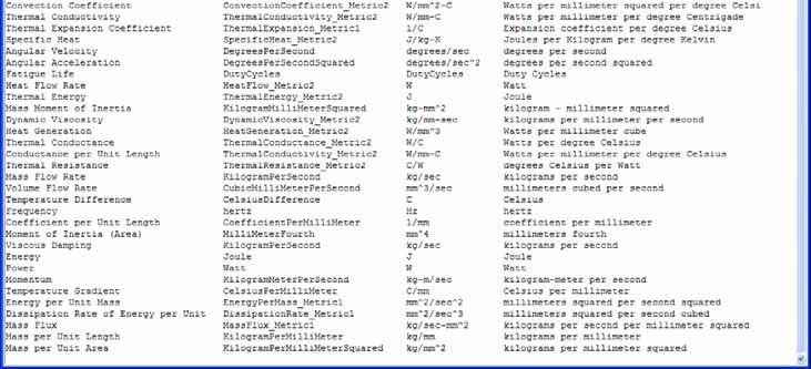
158 158 Constraints Enforced Displacement Enforced Displacement Options Magnitude and direction Normal to selected faces Component Displacement relative to selected coordinate system Managed in the Constraint Container


")


159 159 Constraints Fixed, Translation & Rotation Fixed Constraints (Restraints) All DOF No Translation No Rotation Managed in the Constraints Container


160 160 Constraints Simply Supported Simply Supported Constraint Magnitude and Direction of Support Normal to selected surfaces Managed in the Constraint Container

161 161 Constraints Slider Slider constraint Planar sliding face Sliding direction Managed in the Constraint Container

162 162 Constraints Pinned Pinned Constraint for Cylindrical Surfaces Managed in the Constraint Container


163 163 Constraints Cylindrical Cylindrical Constraint Radial Growth Axial Rotation Axial Growth Relative to selected cylindrical surface Managed in the Constraint Container


164 164 Constraints Roller Roller Constraint Managed in the Constraint Container

165 165 Constraints Symmetric Symmetric Constraint Managed in the Constraint Container


166 166 Constraints Anti-Symmetric Anti-Symmetric Constraint Managed in the Constraint Container


167 167 Constraints Velocity Velocity Constraint Specific to these NX Nastran Solutions SEDFREQ 108 Direct Frequency Response SEDTRAN 109 Direct Transient Response SEMFREQ 111 Modal Frequency Response SEMTRAN 112 Modal Transient Response Managed in the Constraint Container
168 168 Constraints Acceleration Velocity Constraint Specific to these NX Nastran Solutions SEDFREQ 108 Direct Frequency Response SEDTRAN 109 Direct Transient Response SEMFREQ 111 Modal Frequency Response SEMTRAN 112 Modal Transient Response Managed in the Constraint Container


169 169 Constraints Automatic Coupling Coupled degrees of freedom between offset or symmetric meshes Managed in the Constraint Container


170 170 Constraints Manual Coupling Create either Coupled DOF or Constraint Equations between selected nodes Managed in the Constraint Container


171 171 Constraints Enforced Motion Location Enforced Motion Location Constraint Specific to these NX Nastran Solutions SEDFREQ 108 Direct Frequency Response SEDTRAN 109 Direct Transient Response SEMFREQ 111 Modal Frequency Response SEMTRAN 112 Modal Transient Response Managed in the Constraint Container


172 172 Boundary Condition Symbol Display Controls All Boundary Conditions have a Symbol associated and the Style can be changed


173 173 Physical Property Overrides Allows the SIM file to override the Physical properties defined in the FEM file Mesh with Overridden property shown in Red What-if studies


174 174 Custom Units & Units Converter Units Manager create Custom Units for various Measures Units Converter


175 175 Unit Selection Examples Numeric entry for a value can be entered in different units Measure Field Function on the fly measurement from existing geometry Define the magnitude as a constant or variable (eg time dependant) Define the magnitude as a function that calculates a single value Link Existing Field Link to an existing Field Variable Make Constant Converts an expression to a constant value


176 176 Boundary Condition Magnitude Table Field Maths Expression Field Table Based Field Existing Named Variables Tables Field User selected Dependant and Independent columns


177 177 Boundary Condition Magnitude Function Field Pre-defined functions that calculate a value Categories Beams Fluids Gears Geometry Materials Maths Mechanics Misc O Rings Plate Spreadsheet Spring String Units Vibration


178 178 Solution Solution is Solver dependant Solution gathers everything together to perform a solve SIM File can contain many Solutions to study different aspects of the design Only one is active


179 Solution Containers and Re-using Data Simulation Containers All Boundary Conditions, constraints etc are stored in Containers They are then referenced by the Solutions and Subcases Drag n Drop Multiple Subcases Multiple Solutions Benefits Re-use of data Quickly and easily explore effects of different loading conditions Efficient analysis in complex environments 179


180 180 Solution Subcase Management Output Request Object Subcase availability and options will vary according to the active Solver and Solution type Each Solution can have multiple Subcases Loads can be used in any combination of Subcases Subcases can include Pre-Loads like Thermal results from a previous solve


181 181 Solution Attributes Solution Attributes availability and options will vary according to the active Solver and Solution type


182 182 Solution Parameters Exact Version of NX Nastran Solution Attributes availability and options will vary according to the active Solver and Solution type


183 183 Solution Comprehensive Check Solution Comprehensive Check Warnings & Errors Mesh Materials Boundary Conditions Solution


184 184 Solution Report Before Solve Solution Report Before Solve User entered text description/documentation Snapshot screen images HTML Interactive report export


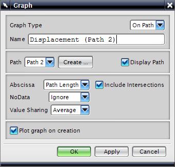
185 185 Solution Solve the Active Solution Solve the Active Solution options Solve interactively (eg using NX Nastran Desktop) Write (export) the solver input file for further job editing or queue management Solve interactively an existing Input file (ie Restart) Edit the Input file and solve directly (useful at add extra Solver specific entries)
186 SIM Part Post-Processing UGS Corp All rights reserved. UGS PLM Software


187 187 NX Integrated Post Processing Viewport Synchronization Viewport Layout Easy selection of results Post Processing Icons Dedicated Post Processing Navigator Dedicated XY Graphing Import of Existing Results for comparison Post Views and Templates


 Existing")
188 188 Results Selection Results Selection from the Post Processing Navigator Ease of navigation through available Results Double mouse click to change the Results display Plot to a Existing Viewport, to a New Viewport or Overlay (combine) Existing display
 Play,")

189 189 Results Animation Results Animation options Number of Frames Delay between frames Full cycle ( forwards then backwards ) Play, Pause, Stop Single frame forwards or backwards During Animation Change the Results Screen rotate/pan/zoom Toggle on/off Meshes Save to Animated GIF

190 190 Results Post View Display Result Set Selection Post View Display Options Styles Contours Elements Isolines, Isosurfaces Mark Arrow, Cube, Sphere, Tensor Absolute or scaled values Coordinate System for results calculation


191 191 Results Post View Display Post View Display Options Results Plot options vary according to the Display type


192 192 Results Post View Display Deformed model display Results domain Free Face Volume Cutting Plane


193 193 Results Post View Color Bar Post View Color Bar Max & Min values Number of colors Color scheme Scale Legend level of detail


194 194 Results Post View Edges & Faces Post View Edges & Faces display & color options Primary Display for Element Edge & Faces Undeformed Display


195 195 Results Identify Identify to probe and display nodal and elemental information Results n Max, or n Min Result values Result Range Selected data saved to Excel for further study


196 196 Results Identify Identify works on all types of Results display


197 197 Results Annotation Markers Results Marker shows max/min of the current active Result Set Max & Min Max only Min only Drag Marker to reposition


198 198 Results Previous / Next Mode or Iteration Quick change to the next Mode or Iteration


199 199 Results Post Views & Templates Post Views store the Post View setup Provides quick and efficient method of controlling displays in different Views Post Views can be saved and are available for re-use


200 200 Results Multiple Viewports Multiple Viewports Different Post Views per Viewport Select all views ports for Synchronised screen rotate/pan/zoon Return the view to Model display


201 201 Results Post View Overlay Post View Overlay Post View changes can be saved to all or selected Post Views


202 202 Plotting Paths Paths defined by Node labels Screen selection Edge selection


203 203 Plotting Paths Graphs can be Overlaid to compare data using same Axis Path and Graph data stored in external file (*.afu)


204 204 Graph Style Edit Graph Style Dynamic Selection of Graph element Graph Title Graph Legend Axis style Axis Labels Axis Numbers Axis Type, Values & Units Curve style


205 205 Graph Style Graph Grid Style Grid Layout Divisions Save the current Graph Settings to the current Template File Save the current Graph Setting to a new Template File


206 206 Graph Probing Data Point Probing and Marking Dynamic Display of curve data points & values Specific curve location values Probe Text Styles


207 207 Graph Probing Peak and Valley locating and Marking

208 208 Graph Probing Fine Tracking and Marking


209 209 Graph Windowing Window into the Graph X Window Y Window X-Y Window No Window to return to full graph


210 210 Solution Report After Solve Solution Report After Solve User entered text description/documentation Snapshot screen images HTML Interactive report export


211 211 Export Visualisation Files Direct export of JT visualisation model Direct export of screen images PNG JPEG GIF TIFF BMP Direct export of Animation Animated GIF
212 Customer Defaults for Simulation UGS Corp All rights reserved. UGS PLM Software

213 213 Customer Defaults General General Default Solver Language Creation of the four simulation files

214 214 Customer Defaults Model Preparation Model Preparation Default values for CAE Topology creation

215 215 Customer Defaults Mesh Display Mesh Display Default Mesh displays for different mesh types Color, Line width, Shrink etc

216 216 Customer Defaults Node & Element Display Node & Element Display Node style Element display quality

217 217 Customer Defaults Mesh Controls Mesh Control defaults

218 218 Customer Defaults Boundary Condition Display Boundary Condition Display Defaults for color, line width and style

219 219 Customer Defaults Threshold Values Nastran Threshold Values Nastran Element quality check threshold values for Tri, Quad, Tet, Hex and Wedge element types

220 220 Customer Defaults Meshing Meshing General defaults for the meshing task

221 221 Customer Defaults Analysis Analysis General and specific for Optimization and Fatigue (Durability)

222 222 Customer Defaults Post Processor Post Processor Defaults for text display Report file names
223 Thank You UGS Corp All rights reserved. UGS PLM Software
NX Advanced FEM. fact sheet
 Advanced FEM fact sheet www.ugs.com Summary Advanced FEM is a comprehensive multi-cad finite element modeling and results visualization product that is designed to meet the needs of experienced CAE analysts.
NX Advanced FEM. Benefits
 Advanced FEM fact sheet Siemens PLM Software www.siemens.com/plm Summary Advanced FEM software is a comprehensive multi-cad finite element modeling and results visualization product that is designed to
SimLab Release Notes. 1 A l t a i r E n g i n e e r i n g
 SimLab 11.0 Release Notes 1 A l t a i r E n g i n e e r i n g System Support extended to load and save GDA/SLB files of size greater than 4GB. Memory allocation is enhanced to support large models. Kubrix
PTC Creo Simulate. Features and Specifications. Data Sheet
 PTC Creo Simulate PTC Creo Simulate gives designers and engineers the power to evaluate structural and thermal product performance on your digital model before resorting to costly, time-consuming physical
SolidWorks. An Overview of SolidWorks and Its Associated Analysis Programs
 An Overview of SolidWorks and Its Associated Analysis Programs prepared by Prof. D. Xue University of Calgary SolidWorks - a solid modeling CAD tool. COSMOSWorks - a design analysis system fully integrated
NX I-deas MasterFEM Complete standalone capabilities for creating FE models and evaluating simulation results
 I-deas MasterFEM Complete standalone capabilities for creating FE models and evaluating simulation results fact sheet Siemens PLM Software www.siemens.com/nx Summary I-deas MasterFEM software is the standalone
NX Advanced Simulation: FE modeling and simulation
 Advanced Simulation: FE modeling and simulation NX CAE Benefits Speed simulation processes by up to 70 percent Increase product quality by rapidly simulating design trade-off studies Lower overall product
SimLab 14.2 Release Notes
 SimLab 14.2 Release Notes Highlights SimLab 14.2 comes with various changes that improve performance and graphics rendering. In addition to java scripting, python scripting is introduced. The enhancements,
SIMCENTER 12 ACOUSTICS Beta
 SIMCENTER 12 ACOUSTICS Beta 1/80 Contents FEM Fluid Tutorial Compressor Sound Radiation... 4 1. Import Structural Mesh... 5 2. Create an Acoustic Mesh... 7 3. Load Recipe... 20 4. Vibro-Acoustic Response
PTC Newsletter January 14th, 2002
 PTC Email Newsletter January 14th, 2002 PTC Product Focus: Pro/MECHANICA (Structure) Tip of the Week: Creating and using Rigid Connections Upcoming Events and Training Class Schedules PTC Product Focus:
Introduction to ANSYS DesignModeler
 Lecture 5 Modeling 14. 5 Release Introduction to ANSYS DesignModeler 2012 ANSYS, Inc. November 20, 2012 1 Release 14.5 Preprocessing Workflow Geometry Creation OR Geometry Import Geometry Operations Meshing
Customized Pre/post-processor for DIANA. FX for DIANA
 Customized Pre/post-processor for DIANA FX for DIANA About FX4D for DIANA FX4D is a general purpose pre/post-processor for CAE simulation. FX4D has been specialized for civil/architectural applications.
2: Static analysis of a plate
 2: Static analysis of a plate Topics covered Project description Using SolidWorks Simulation interface Linear static analysis with solid elements Finding reaction forces Controlling discretization errors
Femap Version
 Femap Version 11.3 Benefits Easier model viewing and handling Faster connection definition and setup Faster and easier mesh refinement process More accurate meshes with minimal triangle element creation
Overview of ABAQUS II. Working with Geometry in ABAQUS III. Working with models Created Outside ABAQUS IV. Material and Section Properties
 ABAQUS TRAINING I. Overview of ABAQUS II. Working with Geometry in ABAQUS III. Working with models Created Outside ABAQUS IV. Material and Section Properties V. Assemblies in ABAQUS VI. Steps, Output,
World-class finite element analysis (FEA) solution for the Windows desktop
 solution for the Windows desktop") World-class finite element analysis (FEA) solution for the Windows desktop fact sheet Siemens PLM Software www.siemens.com/plm/femap Summary Femap software is an advanced engineering analysis environment
World-class finite element analysis (FEA) solution for the Windows desktop fact sheet Siemens PLM Software www.siemens.com/plm/femap Summary Femap software is an advanced engineering analysis environment
pre- & post-processing f o r p o w e r t r a i n
 pre- & post-processing f o r p o w e r t r a i n www.beta-cae.com With its complete solutions for meshing, assembly, contacts definition and boundary conditions setup, ANSA becomes the most efficient and
Fundamentals of Modeling with Simcenter 3D Robin Boeykens
 Fundamentals of Modeling with Simcenter 3D Robin Boeykens robin.boeykens@siemens.com Realize innovation. 3D CAE for the digital twin Simcenter 3D Page 2 Simcenter 3D Engineering Desktop Simcenter 3D Engineering
Simcenter 3D Engineering Desktop
 Simcenter 3D Engineering Desktop Integrating geometry and FE modeling to streamline the product development process Benefits Speed simulation processes by up to 70 percent Increase product quality by rapidly
SimLab 14.1 Release Notes
 SimLab 14.1 Release Notes Highlights SimLab 14.0 introduced the new user interface. SimLab 14.1 enhances the user interface using feedback from customers. In addition many new core features have been added.
Tutorial 1: Welded Frame - Problem Description
 Tutorial 1: Welded Frame - Problem Description Introduction In this first tutorial, we will analyse a simple frame: firstly as a welded frame, and secondly as a pin jointed truss. In each case, we will
Lecture 3 : General Preprocessing. Introduction to ANSYS Mechanical Release ANSYS, Inc. February 27, 2015
 Lecture 3 : General Preprocessing 16.0 Release Introduction to ANSYS Mechanical 1 2015 ANSYS, Inc. February 27, 2015 Chapter Overview In this chapter we cover basic preprocessing operations that are common
SimLab 14.3 Release Notes
 SimLab 14.3 Release Notes Highlights SimLab 14.0 introduced new graphical user interface and since then this has evolved continuously in subsequent versions. In addition, many new core features have been
Installation Guide. Beginners guide to structural analysis
 Installation Guide To install Abaqus, students at the School of Civil Engineering, Sohngaardsholmsvej 57, should log on to \\studserver, whereas the staff at the Department of Civil Engineering should
Autodesk Fusion 360 Training: The Future of Making Things Attendee Guide
 Autodesk Fusion 360 Training: The Future of Making Things Attendee Guide Abstract After completing this workshop, you will have a basic understanding of editing 3D models using Autodesk Fusion 360 TM to
World-class finite element analysis (FEA) solution for the Windows desktop
 solution for the Windows desktop") World-class finite element analysis (FEA) solution for the Windows desktop Benefits Significantly speed up the design process by bringing simulation closer to design and reducing time-to-market Reduce
World-class finite element analysis (FEA) solution for the Windows desktop Benefits Significantly speed up the design process by bringing simulation closer to design and reducing time-to-market Reduce
NX Tutorial - Centroids and Area Moments of Inertia ENAE 324 Aerospace Structures Spring 2015
 NX will automatically calculate area and mass information about any beam cross section you can think of. This tutorial will show you how to display a section s centroid, principal axes, 2 nd moments of
Torsional-lateral buckling large displacement analysis with a simple beam using Abaqus 6.10
 Torsional-lateral buckling large displacement analysis with a simple beam using Abaqus 6.10 This document contains an Abaqus tutorial for performing a buckling analysis using the finite element program
Exercise Guide. Published: August MecSoft Corpotation
 VisualCAD Exercise Guide Published: August 2018 MecSoft Corpotation Copyright 1998-2018 VisualCAD 2018 Exercise Guide by Mecsoft Corporation User Notes: Contents 2 Table of Contents About this Guide 4
NEi FEA. IRONCAD Advanced FEA. IRONCAD Advanced FEA. NEi FEA
 2011 Overview has been designed as a universal, adaptive and user-friendly graphical user interface for geometrical modeling, data input and visualization of results for all types of numerical simulation
SOLIDWORKS 2016: A Power Guide for Beginners and Intermediate Users
 SOLIDWORKS 2016: A Power Guide for Beginners and Intermediate Users The premium provider of learning products and solutions www.cadartifex.com Table of Contents Dedication... 3 Preface... 15 Part 1. Introducing
Convergent Modeling and Reverse Engineering
 Convergent Modeling and Reverse Engineering 25 October 2017 Realize innovation. Tod Parrella NX Design Product Management Product Engineering Solutions tod.parrella@siemens.com Realize innovation. Siemens
Introduction to ANSYS
 Lecture 1 Introduction to ANSYS ICEM CFD 14. 0 Release Introduction to ANSYS ICEM CFD 1 2011 ANSYS, Inc. March 22, 2015 Purpose/Goals Ansys ICEM CFD is a general purpose grid generating program Grids for
Introduction to ANSYS DesignModeler
 Lecture 9 Beams and Shells 14. 5 Release Introduction to ANSYS DesignModeler 2012 ANSYS, Inc. November 20, 2012 1 Release 14.5 Beams & Shells The features in the Concept menu are used to create and modify
Lesson 4: Surface Re-limitation and Connection
 Lesson 4: Surface Re-limitation and Connection In this lesson you will learn how to limit the surfaces and form connection between the surfaces. Lesson contents: Case Study: Surface Re-limitation and Connection
Topology Optimization for Designers
 TM Topology Optimization for Designers Siemens AG 2016 Realize innovation. Topology Optimization for Designers Product Features Uses a different approach than traditional Topology Optimization solutions.
Introduction to ANSYS ICEM CFD
 Lecture 1 Introduction to ANSYS ICEM CFD 14.5 Release Introduction to ANSYS ICEM CFD 2012 ANSYS, Inc. April 1, 2013 1 Release 14.5 Purpose/Goals Ansys ICEM CFD is a general purpose grid generating program
Section 8.3: Examining and Repairing the Input Geometry. Section 8.5: Examining the Cartesian Grid for Leakages
 Chapter 8. Wrapping Boundaries TGrid allows you to create a good quality boundary mesh using a bad quality surface mesh as input. This can be done using the wrapper utility in TGrid. The following sections
Workshop 15. Single Pass Rolling of a Thick Plate
 Introduction Workshop 15 Single Pass Rolling of a Thick Plate Rolling is a basic manufacturing technique used to transform preformed shapes into a form suitable for further processing. The rolling process
SDC. Engineering Analysis with COSMOSWorks. Paul M. Kurowski Ph.D., P.Eng. SolidWorks 2003 / COSMOSWorks 2003
 Engineering Analysis with COSMOSWorks SolidWorks 2003 / COSMOSWorks 2003 Paul M. Kurowski Ph.D., P.Eng. SDC PUBLICATIONS Design Generator, Inc. Schroff Development Corporation www.schroff.com www.schroff-europe.com
Engineering Analysis with
 Engineering Analysis with SolidWorks Simulation 2013 Paul M. Kurowski SDC PUBLICATIONS Schroff Development Corporation Better Textbooks. Lower Prices. www.sdcpublications.com Visit the following websites
Training Course Content
 Pioneering engineering software systems, support & services. Training Course Content 29800 Middlebelt Road Suite 100 Farmington Hills, MI 48334 United States of America Tel: +1 248 737 9760 Fax: +1 248
FEMAP Freebody Deep-Dive Patrick Kriengsiri, FEMAP Development
 Femap Symposium 2015 Huntsville FEMAP Freebody Deep-Dive Patrick Kriengsiri, FEMAP Development Realize Innovation. FEMAP Freebody Deep Dive Topics What is a Freebody? Recovering Grid Point Forces in NASTRAN
FEMAP v New Features and Corrections Updates and Enhancements
 FEMAP v11.0.1 New Features and Corrections Updates and Enhancements Connection Properties, Regions, and Connectors Geometry Model, Delete, Mesh now automatically deletes any Connection Regions where all
CHAPTER 8 FINITE ELEMENT ANALYSIS
 If you have any questions about this tutorial, feel free to contact Wenjin Tao (w.tao@mst.edu). CHAPTER 8 FINITE ELEMENT ANALYSIS Finite Element Analysis (FEA) is a practical application of the Finite
SOLIDWORKS Parametric Modeling with SDC. Covers material found on the CSWA exam. Randy H. Shih Paul J. Schilling
 Parametric Modeling with SOLIDWORKS 2015 Covers material found on the CSWA exam Randy H. Shih Paul J. Schilling SDC PUBLICATIONS Better Textbooks. Lower Prices. www.sdcpublications.com Powered by TCPDF
DMU Engineering Analysis Review
 DMU Engineering Analysis Review Overview Conventions What's New? Getting Started Entering DMU Engineering Analysis Review Workbench Generating an Image Visualizing Extrema Generating a Basic Analysis Report
DMU Engineering Analysis Review
 Page 1 DMU Engineering Analysis Review Preface Using This Guide Where to Find More Information Conventions What's New? Getting Started Inserting a CATAnalysis Document Using DMU Space Analysis From CATAnalysis
Using MSC.Nastran for Explicit FEM Simulations
 3. LS-DYNA Anwenderforum, Bamberg 2004 CAE / IT III Using MSC.Nastran for Explicit FEM Simulations Patrick Doelfs, Dr. Ingo Neubauer MSC.Software GmbH, D-81829 München, Patrick.Doelfs@mscsoftware.com Abstract:
What s new in Femap 9.3
 What s new in Femap 9.3 fact sheet www.ugs.com/femap Summary Femap version 9.3 is the latest release of UGS robust pre and post processor for engineering finite element analysis (FEA). Femap software is
Engineering Analysis with SolidWorks Simulation 2012
 Engineering Analysis with SolidWorks Simulation 2012 Paul M. Kurowski SDC PUBLICATIONS Schroff Development Corporation Better Textbooks. Lower Prices. www.sdcpublications.com Visit the following websites
NX Advanced Simulation
 Siemens PLM Software Integrating FE modeling and simulation streamlines product development process Benefits Speed simulation processes by up to 70 percent Perform accurate, reliable structural analysis
Lecture 7: Mesh Quality & Advanced Topics. Introduction to ANSYS Meshing Release ANSYS, Inc. February 12, 2015
 Lecture 7: Mesh Quality & Advanced Topics 15.0 Release Introduction to ANSYS Meshing 1 2015 ANSYS, Inc. February 12, 2015 Overview In this lecture we will learn: Impact of the Mesh Quality on the Solution
Equipment Support Structures
 Equipment Support Structures Overview Conventions What's New? Getting Started Setting Up Your Session Creating a Simple Structural Frame Creating Non-uniform Columns Creating Plates with Openings Bracing
SolidWorks Implementation Guides. User Interface
 SolidWorks Implementation Guides User Interface Since most 2D CAD and SolidWorks are applications in the Microsoft Windows environment, tool buttons, toolbars, and the general appearance of the windows
Modeling Bolted Connections. Marilyn Tomlin CAE COE / Siemens Corporation
 Modeling Bolted Connections Marilyn Tomlin CAE COE / Siemens Corporation Overview Bolted Connection Engineering Judgment Modeling Options Summary Typical Bolted Connection Gasket Bolt Nut Washer Technology
Generative Part Structural Analysis Fundamentals
 CATIA V5 Training Foils Generative Part Structural Analysis Fundamentals Version 5 Release 19 September 2008 EDU_CAT_EN_GPF_FI_V5R19 About this course Objectives of the course Upon completion of this course
Lecture 5 Modeling Connections
 Lecture 5 Modeling Connections 16.0 Release Introduction to ANSYS Mechanical 1 2015 ANSYS, Inc. February 27, 2015 Chapter Overview In this chapter, we will extend the discussion of contact control begun
Live Classroom Curriculum Guide
 Curriculum Guide Live Classroom Curriculum Guide Milling using Pro/ENGINEER Wildfire 4.0 Pro/ENGINEER Mechanica Simulation using Pro/ENGINEER Wildfire 4.0 Introduction to Pro/ENGINEER Wildfire 4.0 Pro/ENGINEER
Obtaining Meshable Surfaces
 Chapter 2 Obtaining Meshable Surfaces Exercise 2a: Importing and Repairing CAD Geometry Overview of Exercise Strategy: Import CAD geometry and organize your model using the Assembly Hierarchy. Evaluate
Parametric Modeling with SolidWorks
 Parametric Modeling with SolidWorks 2012 LEGO MINDSTORMS NXT Assembly Project Included Randy H. Shih Paul J. Schilling SDC PUBLICATIONS Schroff Development Corporation Better Textbooks. Lower Prices. www.sdcpublications.com
Parametric Modeling with SOLIDWORKS 2017
 Parametric Modeling with SOLIDWORKS 2017 NEW Contains a new chapter on 3D printing Covers material found on the CSWA exam Randy H. Shih Paul J. Schilling SDC PUBLICATIONS Better Textbooks. Lower Prices.
3. Preprocessing of ABAQUS/CAE
 3.1 Create new model database 3. Preprocessing of ABAQUS/CAE A finite element analysis in ABAQUS/CAE starts from create new model database in the toolbar. Then save it with a name user defined. To build
SIMULATION CAPABILITIES IN CREO
 SIMULATION CAPABILITIES IN CREO Enhance Your Product Design with Simulation & Using digital prototypes to understand how your designs perform in real-world conditions is vital to your product development
Normal Modes - Rigid Element Analysis with RBE2 and CONM2
 APPENDIX A Normal Modes - Rigid Element Analysis with RBE2 and CONM2 T 1 Z R Y Z X Objectives: Create a geometric representation of a tube. Use the geometry model to define an analysis model comprised
CATIA V5-6R2015 Product Enhancement Overview
 Click to edit Master title style CATIA V5-6R2015 Product Enhancement Overview John Montoya, PLM Technical Support March 2015 1 2010 Inceptra LLC. All rights reserved. Overview of Enhanced Products Overview
SpaceClaim Professional The Natural 3D Design System. Advanced Technology
 SpaceClaim Professional The Natural 3D Design System SpaceClaim Professional is the 3D productivity tool for engineers who contribute to the design and manufacture of mechanical products across a broad
Lesson: Static Stress Analysis of a Connecting Rod Assembly
 Lesson: Static Stress Analysis of a Connecting Rod Assembly In this tutorial we determine the effects of a 2,000 pound tensile load acting on a connecting rod assembly (consisting of the rod and two pins).
Sheet Metal Overview. Chapter. Chapter Objectives
 Chapter 1 Sheet Metal Overview This chapter describes the terminology, design methods, and fundamental tools used in the design of sheet metal parts. Building upon these foundational elements of design,
FEMAP FEMAP Modeler. Meshing: Subdivision and semi-automatic meshing of solids Automatic and mapped meshing (with quads or bricks), including biasing
, including biasing") FEMAP FEMAP Modeler Overview FEMAP V9.3 is a Windows-native pre- and post-processor used by engineering organizations world wide to model various products, processes, and systems. Its graphical user interface
FEMAP FEMAP Modeler Overview FEMAP V9.3 is a Windows-native pre- and post-processor used by engineering organizations world wide to model various products, processes, and systems. Its graphical user interface
ANSYS Element. elearning. Peter Barrett October CAE Associates Inc. and ANSYS Inc. All rights reserved.
 ANSYS Element Selection elearning Peter Barrett October 2012 2012 CAE Associates Inc. and ANSYS Inc. All rights reserved. ANSYS Element Selection What is the best element type(s) for my analysis? Best
The Essence of Result Post- Processing
 APPENDIX E The Essence of Result Post- Processing Objectives: Manually create the geometry for the tension coupon using the given dimensions then apply finite elements. Manually define material and element
Create Complex Surfaces
 Create Complex Surfaces In this lesson, you will be introduced to the functionalities available in the Generative Surface Design workbench. Lesson content: Case Study: Surface Design Design Intent Stages
Element Order: Element order refers to the interpolation of an element s nodal results to the interior of the element. This determines how results can
 TIPS www.ansys.belcan.com 鲁班人 (http://www.lubanren.com/weblog/) Picking an Element Type For Structural Analysis: by Paul Dufour Picking an element type from the large library of elements in ANSYS can be
CATIA Surface Design
 CATIA V5 Training Exercises CATIA Surface Design Version 5 Release 19 September 2008 EDU_CAT_EN_GS1_FX_V5R19 Table of Contents (1/2) Creating Wireframe Geometry: Recap Exercises 4 Creating Wireframe Geometry:
Curriculum Guide. Creo 4.0
 Curriculum Guide Creo 4.0 Live Classroom Curriculum Guide Update to Creo Parametric 4.0 from Creo Parametric 3.0 Introduction to Creo Parametric 4.0 Advanced Modeling using Creo Parametric 4.0 Advanced
I-deas NX Series Master Modeler Foundation capabilities for feature-based variational solid modeling
 I-deas Series Master Modeler Foundation capabilities for feature-based variational solid modeling fact sheet www.ugs.com Summary I-deas Series Master Modeler is the core design module for the I-deas product
Appendix B: Creating and Analyzing a Simple Model in Abaqus/CAE
 Getting Started with Abaqus: Interactive Edition Appendix B: Creating and Analyzing a Simple Model in Abaqus/CAE The following section is a basic tutorial for the experienced Abaqus user. It leads you
Multiframe Windows Version 16. User Manual
 Multiframe Windows Version 16 User Manual Bentley Systems, Incorporated 2013 License & Copyright Multiframe Program & User Manual 2013 Bentley Systems, Incorporated iii Table of Contents License & Copyright...
Module 1: Basics of Solids Modeling with SolidWorks
 Module 1: Basics of Solids Modeling with SolidWorks Introduction SolidWorks is the state of the art in computer-aided design (CAD). SolidWorks represents an object in a virtual environment just as it exists
solidthinking Design Release Notes
 solidthinking Design 2017.2 Release Notes The solidthinking Design package includes Inspire and Evolve 2017.2. Inspire is available on Windows, while Evolve is available on Windows and Mac. solidthinking
Solidworks 2006 Surface-modeling
 Solidworks 2006 Surface-modeling (Tutorial 2-Mouse) Surface-modeling Solid-modeling A- 1 Assembly Design Design with a Master Model Surface-modeling Tutorial 2A Import 2D outline drawing into Solidworks2006
SimWise. 3D Dynamic Motion, and Stress Analysis. integrated with Alibre Design
 SimWise 3D Dynamic Motion, and Stress Analysis integrated with Alibre Design SimWise 4D for Alibre Integrated Motion Simulation and Stress Analysis SimWise 4D is a software tool that allows the functional
Generative Part Structural Analysis Expert
 CATIA V5 Training Foils Generative Part Structural Analysis Expert Version 5 Release 19 September 2008 EDU_CAT_EN_GPE_FI_V5R19 About this course Objectives of the course Upon completion of this course
ARCHITECTURE & GAMES. A is for Architect Simple Mass Modeling FORM & SPACE. Industry Careers Framework. Applied. Getting Started.
 A is for Architect Simple Mass Modeling One of the first introductions to form and space usually comes at a very early age. As an infant, you might have played with building blocks to help hone your motor
Manipulating the Boundary Mesh
 Chapter 7. Manipulating the Boundary Mesh The first step in producing an unstructured grid is to define the shape of the domain boundaries. Using a preprocessor (GAMBIT or a third-party CAD package) you
FEMAP All Rights Reserved NASTRAN 1
 FEMAP 1 Overview Femap V10.3 is a Windows-native pre- and postprocessor used by engineering organizations world wide to model various products, processes, and systems. Its graphical user interface provides
Introduction to ANSYS Mechanical
 Lecture 6 Modeling Connections 15.0 Release Introduction to ANSYS Mechanical 1 2012 ANSYS, Inc. February 12, 2014 Chapter Overview In this chapter, we will extend the discussion of contact control begun
Equipment Support Structures
 Page 1 Equipment Support Structures Preface Using This Guide Where to Find More Information Conventions What's New? Getting Started Setting Up Your Session Creating a Simple Structural Frame Creating Non-uniform
Creo for Analyst. Overview
 Creo for Analyst Overview In this course, you will learn how to utilize the core functionality enhancements in Creo Parametric 2.0. First, you will become familiar with using and customizing the new ribbon
Creo 3.0. Curriculum Guide
 Creo 3.0 Curriculum Guide Live Classroom Curriculum Guide Update to Creo Parametric 3.0 from Creo Parametric 2.0 Introduction to Creo Parametric 3.0 Advanced Modeling using Creo Parametric 3.0 Advanced
SOLIDWORKS - SYLLABUS
 SOLIDWORKS - SYLLABUS SolidWorks Syllabus 1 Introduction to CAD, CAE, PDM Features of SolidWorks, Total Duration : 90 Hour Various products available in SolidWorks for Product Design, Simulation, Communication
Chapter 2 Parametric Modeling Fundamentals
 2-1 Chapter 2 Parametric Modeling Fundamentals Create Simple Extruded Solid Models Understand the Basic Parametric Modeling Procedure Create 2-D Sketches Understand the Shape before Size Approach Use the
Chapter 6. Concept Modeling. ANSYS, Inc. Proprietary Inventory # May 11, ANSYS, Inc. All rights reserved.
 Chapter 6 Concept Modeling 6-1 Contents Concept Modeling Creating Line Bodies Modifying i Line Bodies Cross Sections Cross Section Alignment Cross Section Offset Surfaces From Lines Surfaces From Sketches
FreeStyle Shaper & Optimizer
 FreeStyle Shaper & Optimizer Preface What's New Getting Started Basic Tasks Advanced Tasks Workbench Description Customizing Glossary Index Dassault Systèmes 1994-99. All rights reserved. Preface CATIA
midas NFX An insight into midas NFX
 midas NFX An insight into midas NFX Total Analysis Solutions for Multi-disciplinary Optimum Design Part 1. Work environment Multi-disciplinary CAE solutions in one unique work environment 1 Part 1. Work
Tekla Structures Analysis Guide. Product version 21.0 March Tekla Corporation
 Tekla Structures Analysis Guide Product version 21.0 March 2015 2015 Tekla Corporation Contents 1 Getting started with analysis... 7 1.1 What is an analysis model... 7 Analysis model objects...9 1.2 About
SAMCEF for ROTORS. Chapter 3.2: Rotor modeling. This document is the property of SAMTECH S.A. MEF A, Page 1
 SAMCEF for ROTORS Chapter 3.2: Rotor modeling This document is the property of SAMTECH S.A. MEF 101-03-2-A, Page 1 Table of contents Introduction Introduction 1D Model 2D Model 3D Model 1D Models: Beam-Spring-
3D Design with 123D Design
 3D Design with 123D Design Introduction: 3D Design involves thinking and creating in 3 dimensions. x, y and z axis Working with 123D Design 123D Design is a 3D design software package from Autodesk. A
Creating and Analyzing a Simple Model in Abaqus/CAE
 Appendix B: Creating and Analyzing a Simple Model in Abaqus/CAE The following section is a basic tutorial for the experienced Abaqus user. It leads you through the Abaqus/CAE modeling process by visiting