December 3, :30 to 5:30 pm. Speaker Name: Tom Short, P.E. Course Title: Taking A Step Into The World Of 3D
|
|
|
- Lewis Hart
- 5 years ago
- Views:
Transcription
1 Las Vegas, Nevada December 3, :30 to 5:30 pm Speaker Name: Tom Short, P.E. Course Title: Taking A Step Into The World Of 3D Course ID: GD122 Course Outline: Are you an experienced AutoCAD 2D user who s been wondering how to get started in 3D? If so, this is the course for you regardless if you work in mechanical design or architecture. Take the Giant Step, spend four hours with Tom and learn how to create, manipulate, and display solids in AutoCAD You ll walk away with the understanding and techniques to get you started. This is also an excellent background information for both Mechanical and Architectural Desktop.
2 Part 1 Here s Looking at you Controlling the UCS Controlling the Viewpoint Controlling the Display Hide & Shade Controlling the View Ports Controlling the Clipping Planes Capturing and Inserting Images 2


3 Step 1 The User Coordinate System Open drawing S102.dwg Display the UCS Moving the UCS UCS Properties 3


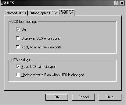
4 Step 1 Continued The UCS Icon Flyout The UCS Dialog Box 4


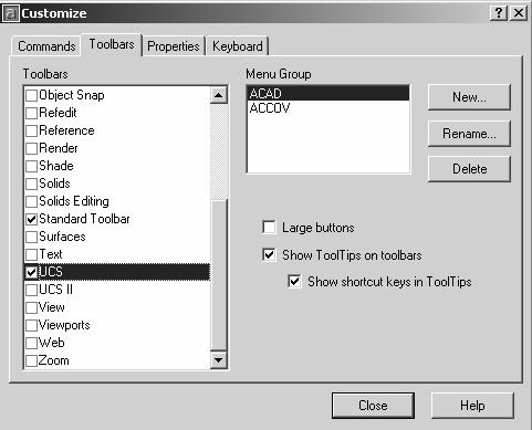
5 Step 1 Continued The UCS Toolbars 5


6 Step 2 Controlling the Viewpoint. Open drawing S107.dwg. Rotate Up & Down. Rotate Side to Side Roll Free 6
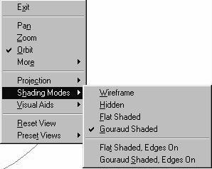


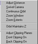
7 Step 3 Controlling the Display, Hide & Shade Click on Orbit then Right Mouse 7
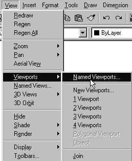
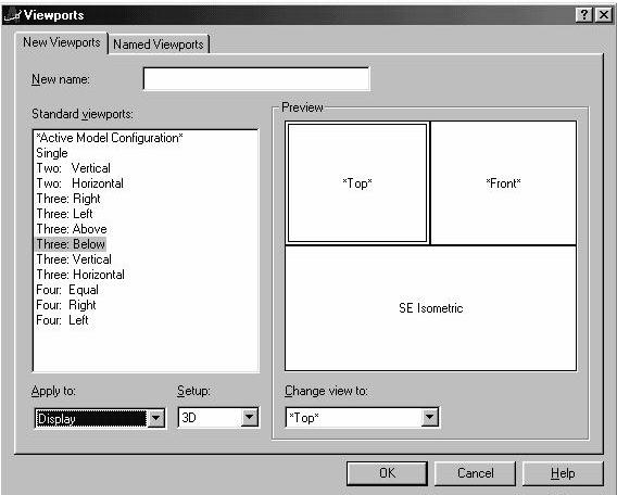
8 Step 4 Controlling the Viewports. Open drawing S112.dwg. 8


9 Step 5 Controlling the Clipping Planes. Open drawing S114.dwg. Click on Orbit then Right Mouse The front clipping plane, which is parallel to the screen is on Adjusts position of clipping plane 9


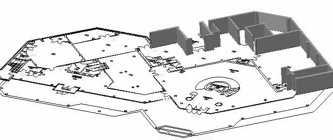
10 Step 6 Capturing & inserting Images Open drawing S115.dwg. 10
11 Part 2 Like a rock 1. Creating and Combining Boxes 2. Creating and Combining Cylinders 3. Using the Torus Primitive 4. The Shell Command 5. Mass and Geometric Properties 11
12 Step 1 Creating and Combining Boxes Start a new file Command: box Specify corner of box or [CEnter] <0,0,0>: Specify corner or [Cube/Length]: 4,4 Specify height: 1.5 Command:box Specify corner of box or [CEnter] <0,0,0>: 0,4,0 Specify corner or [Cube/Length]: 4,5,6 Set view to SE Isometric Command: ucs Current ucs name: *WORLD* Enter an option [New/Move/orthoGraphic/Prev/Restore/Save/Del/Apply/?/World] <World>: x Specify rotation angle about X axis <90>: 90 Command: ucs Current ucs name: *NO NAME* Enter an option [New/Move/orthoGraphic/Prev/Restore/Save/Del/Apply/?/World] <World>: o Specify new origin point <0,0,0>: end of Pick upper back corner of second box Command: box Specify corner of box or [CEnter] <0,0,0>: 1,0,0 Specify corner or [Cube/Length]: c Specify length: 2 Command: union Select objects: all 3 found 12


13 Step 2 Creating and Combining Cylinders Start a New Drawing CYLINDER Number 1 Center point: 0,0,0 Radius: 2 Height of Cylinder: 1 CYLINDER Number 2 Center point: 0,0,0 Radius: 0.75 Height of Cylinder: 5 Union Cylinders 1 and 2 CYLINDER Number 3 Center point: 0,0,0 Radius: 0.5 Height of Cylinder: 5 Subtract Cylinder 3 from the combination of 1 and 2, we ll call this the solid. CYLINDER Number 4 Center point: 1.5,0,0 Radius:.25 Height of cylinder: 1 Use ARRAY to make copies: Array Polar Subtract the four holes from the solid. CYLINDER Number 5 Now put a hole through the upper end of the shaft parallel to the Y axis. Rotate the UCS 90 degrees about the X axis. Create cylinder Number 5 with center at 0,4,0 and a 0.25 radius with a height of 1.0 Subtract cylinder 5 from the solid. 13

14 Step 3 Using the Torus Primitive The torus or doughnut requires 3 dimensions: the center, the radius of the torus, and the radius of the tube. Start a New Drawing Create Torus Number 1 with center at 0,0,0; radius = 1.125; radius =1.5 Create a Cylinder with center at 0,0,2; radius = 0.75; height = 4.0 Subtract the cylinder from the torus. This is the Solid Rotate the UCS about the X axis 90 degrees Create Torus Number 2 with center at 0,0,0; radius = 3.0; radius = 1.25 Subtract Torus Number 2 from the Solid Rotate the UCS about the Y axis 90 degrees Create Torus Number 3 with center at 0,0,0; radius = 3.0; radius = 1.25 Subtract the Torus Number 3 from the Solid 14


15 Step 4 The Shell Command 15
 Enter Input wall thickness of 0.25 (a negative value makes box bigger) Enter Enter 16")
16 Step 4 The Shell Command Continued Start a New Drawing Box from 0,0,0 to 5,4,3 Select Shell Icon Select Box Select Top Face (no indication of selection is shown) Enter Input wall thickness of 0.25 (a negative value makes box bigger) Enter Enter 16

17 Step 5 Mass and Geometric Properties SOLIDS Mass: Volume: Bounding box: X: Y: Z: Centroid: X: Y: Z: Moments of inertia: X: Y: Z: Products of inertia: XY: YZ: ZX: Radii of gyration: X: Y: Z: Principal moments and XYZ directions about centroid: I: along [ ] J: along [ ] K: along [ ] 17
18 Part 3 We Have Liftoff 1. The Extrude Command 2. The Draft Angle 3. Changing Face Draft Angle & Face Colors 4. Extrude Along a 2D Path 5. Extrude Along a 3D Path 6. Extrude a Face 7. The Intersect Command 8. The Boundary Command 9. The Revolve Command 18


19 Step 1 The Extrude Command Open Part S301.dwg Extrude the Polyline and Circles 3 units. Subtract the extruded circles. 19
20 Step 1 Continued What Shapes Can You Extrude? Open drawing S302.dwg Any shape that is: Closed Flat (planar) Does not cross its self Contains no islands can be extruded You can extrude several shapes in one command. 20
 Extrude 146 meters with a draft angle of: Extrusion taper angle <0>: 'cal Initializing.")
21 Step 2 The Draft Angle. Open the drawing S303.dwg Draw a square 250 x 250 (that s meters!) Extrude 146 meters with a draft angle of: Extrusion taper angle <0>: 'cal Initializing...>> Expression: atan(125/146) What happens if the angle is smaller, 10 degrees? What happens if the angle is larger, 40 degrees? 21

22 Step 3 Changing the Draft Angle on a Face and Face Colors. Open the drawing S304.dwg. Extrude the rectangle 75 mm with a draft (taper) angle of 3.0 degrees. Shell with a wall thickness of 5 mm and an open top. Change the color of this face to yellow. Select Taper Faces and select the yellow face. Pick end point B as the Base point and end point P as another point. Input an angle of 12.0 degrees. The face is rotated about the green arrow. Positive rotation is the curl of your fingers when you put your right thumb along the green arrow and your first finger along the light blue. 22

23 Step 4 Extruding along 2D Path. Open the drawing S305.dwg. There are six circles and six 2D paths each starting at the center of the circle. The paths are a: A. Line B. Arc C. Polyline D. Fitted Polyline E. Splined Polyline F. Spline The procedure is: Command: Extrude Current wire frame density: ISOLINES=4 Select objects: 1 found Select objects: Specify height of extrusion or [Path]: Path Select extrusion path: The extruded shape can be any of the shapes that could be extruded a distance. The shell command will turn the rod into tube.only one shell per solid. Negative values for the offset shells to the outside of the part. 23
24 Step 5 Extruding along a 3D Path. Open the drawing S306.dwg. There are three circles and three 3D paths each starting at the center of the circle. The paths are a: A. 3D Polyline B. Splined 3D Polyline C. 3D NURBS Spline Only A, the 3D Polyline containing lines, can be used as a path! Open the drawing S307.dwg. Extrude a rail for the stairway. Detail shows: Object 3D Polyline Path 24

25 Step 6 Extrude a Face Start a new drawing. Construct a Box from 0,0,0 to 5,4,2. Select Extrude Faces, pick this face, a distance of 1.0 Select Rotate Faces. pick this face, Pick 2 endpoints at the yellow arrow for an axis, at an angle of +30 Select Extrude Faces, a distance of +2.0 pick this face, 25

26 Step 7 The Intersect command Open the drawing S308.dwg. Union, Subtract, and Intersect are much like a 3D version of trim. There are 3 ways to trim the circles and three ways to combine the solids. Open the drawing S309.dwg. Extrude the left shape 20 and the right face +20 and then intersect the two solids. The pagoda roof can be shelled. To exclude the bottom face, rotate the part and pick in the face. The thickness is 3. 26

27 Step 8 The Boundary Command Open the drawing S310.dwg. The Boundary command is much like Batch. Pick a point inside the shape but outside the circles and six Boundaries are created. These are sort of 2D solids that have area but no thickness. They can be Unioned and Subtracted and can be extruded into 3D Solids. 27

28 Step 8 The Boundary Command Continued Open the drawing S311.dwg. Use the Boundary command to build a 3D wall. Pick a point inside the wall and then extrude the Region +10 Pick Here Pick Here 28


29 Step 9 The Revolve Command Open the drawing S312.dwg. Any closed shape can be revolved by any angle about any axis, including an edge, that does not pass through the part. Revolve the shape 180 degrees about the axis A. Which way the part rotates depends on which end of AB you pick first, the right hand rule. Change the color of two faces. Open the drawing S313.dwg Revolve the shape about axis AB or it s edge for 360 degrees. 29
30 Part 4 The CadOMatic It Slices, It Dices 1. The Slice Command 2. The Section Command 3. The Separate Command 4. The Imprint Command 5. Move and Offset Faces 6. Copy Faces and Edges 30

31 Step 1 The Slice Command Open the drawing S401.dwg. The Slice command will divide a part into two parts by cutting along a plane. You can keep either one or both of the new parts. We ll slice along the YZ plane through 0,0,0 and keep the left part by picking a point with a negative X. Command: slice Select objects: L 1 found Select objects: Specify first point on slicing plane by [Object/Zaxis/View/XY/YZ/ZX/3points] <3points>: YZ Specify a point on the YZplane <0,0,0>: Specify a point on desired side of the plane or [keep Both sides]: 1,0,0 31

32 Step 2 The Section Command Open the drawing S402.dwg. The Section command will create a 2D section of a part on a plane through the part. The section is one object and is a Region. We ll section along the YZ plane through 0,0,0. The section is copied to show it is one object. The part is sliced, the UCS rotated into the plane of the section and the section crosshatched to demonstrate one application. In the second example the part is sliced keeping both halves. One half is moved 0.25 units, the section is extruded 0.25 units and all three points unioned. 32

33 Step 3 The Separate Command Open the drawing S403.dwg. We ll slice along the XY plane through 0,0,0 and keep the top part by picking a point with a positive Z. This looks like it is two parts but it is only ONE! To change it into two parts use the Separate command. This changes any part that has a separation by space into individual parts. (it does NOT separate a solid into it s primitives.) 33
34 Step 4 The Imprint Command Open the drawing S404.dwg. Imprint lets you imprint a Line, Arc, Spline, or Pline onto a face which divides the face into two faces. Imprint the Line on the vertical face and the Spline on the top face. Rotate the new vertical face 25 degrees. Base Point. Extrude the new face from the Spline by


35 Step 5 Move and Offset Faces Open the drawing S405.dwg. The Offset and Move Faces commands work very similar to the 2D Move and Offset. Offset this face a 10 ( minus numbers make the part smaller.) 35


36 Step 5 Move and Offset Faces Continued Move this face a distance of 20,0,0 just like the 2D move command you can input a distance or a base point and a second point. Moving holes is one of the great uses of the Move Faces command. 36

37 Step 6 Copy Faces and Edges You can copy any faces and any edges. The copies of flat faces are regions which can be extruded or revolved. Copies of curved faces are Bodies. Copies of edges are Lines, Arcs, Polylines, or Splines. 37
38 Part 5 Round and Round We Go 1. Creating Fillets 2. When Fillets Fail 3. Creating Chamfers 4. Finding Interference between Solids 38

39 Step 1 Creating Fillets Open the drawing S501.dwg. You can put FILLETS on the inside edges and the outside edges (these may be called rounds ) of solids. It is NOT necessary to move the UCS into the plane of the fillet before creating. There is no special solid fillet command just use the Fillet command in the Modify pulldown. But the command does have special features for solids. To put a fillet at point E in 2D you would select the two lines at point E in the ABCE plane. In 3D you select the edge or edges of the solid you want filleted, in this case edge DE. First Union the box and the wedge and Subtract the hole. Then put a 1.0 radius fillet at AB and DE and then a 0.3 radius fillet at AC. 39
40 Step 1 Creating Fillets Continued Open the drawing S502.dwg. Put a 0.25 fillet at the intersection of the cylinder and the block and the intersection of the two cylinders. Note the system color. 40
41 Step 1 Creating Fillets Continued Open the drawing S503.dwg. Put a 0.75 fillet on these two edges. Select Fillet again and pick this edge and accept the radius of Touch C for chain and pick the same edge again. Note that the chain selects edges until it gets to a sharp corner where it stops. 41

![25 unit fillet on the top edge using chain.. FILLET Current settings: Mode = TRIM, Radius = 1.0000 Select first object or [Polyline/Radius/Trim]: Enter fillet radius <1.0000>: 2.](/docs-images/87/96170651/images/42-2.jpg "25 Select an edge or [Chain/Radius]: c Select an edge chain or [Edge/Radius]: Select an edge chain or [Edge/Radius]: 8 edge(s) selected for fillet.")
42 Step 2 When Fillets Fail. Open the drawing S504.dwg. Fillet is too large: Try to Place a 1.00 fillet on this edge. In AutoCAD 2000i this would work but in 2002 it fails, the largest fillet is Open the drawing S5041.dwg. The plate is 2.0 units thick. Try to place a 2.25 unit fillet on the top edge using chain.. FILLET Current settings: Mode = TRIM, Radius = Select first object or [Polyline/Radius/Trim]: Enter fillet radius <1.0000>: 2.25 Select an edge or [Chain/Radius]: c Select an edge chain or [Edge/Radius]: Select an edge chain or [Edge/Radius]: 8 edge(s) selected for fillet. Modeling Operation Error: Blends too complex to reorder. Failed to perform blend. Failure while filleting. The first thing to try is a smaller fillet! 42
43 Step 2 When Fillets Fail. Open the drawing S505.dwg. Union the box and the tube. Try to put a 5.0 fillet at the intersection of the tube and the top. Fillet is too complex for current modeler: Whoops! This one works now as well if you use chain. Open the drawing S505A.dwg. Put a 10 unit fillet around the top. Select the edges one at a time but miss one of them. It is better to use chain. 43
44 Step 3 Creating Chamfers Open the drawing S506.dwg.. Solids could be chamfered by creating a solid wedge and subtracting it from the solid. These two steps are done automatically with the CHAMFER command. As in solid fillets, it s not necessary to reorient the UCS. As in 2D, chamfers are specified by two distances. Put a 45 degree chamfer on the edge CF at 0.5 measured perpendicular to the edge. This edge is on the corner of the two surfaces CDEF and BCFG. 44


45 Step 4 The Interference Command Open the drawing S507.dwg. The star wheel and the shaft are assembled. Test to see if there is any interference between the two parts. Use the interference command. 45
 Select second set of solids: Select objects: 1 found Select objects: (Enter) Comparing 1 solid against 1")
46 Command: csgwb Interfere... Step 4 The Interference Select objects: 1 found Command Continued Select objects: (Enter) Select second set of solids: Select objects: 1 found Select objects: (Enter) Comparing 1 solid against 1 solid. Interfering solids (first set): 1 (second set): 1 Interfering pairs : 1 Create interference solids? [Yes/No] <N>: YES Command: Move Select objects: Last 1 found Select objects: Specify base point or displacement: Specify second point of displacement or <use first point as displacement>: This tells you there is interference. This is the interference solid moved for clarity. It can be measured or could be subtracted from the hub. 46
47 Part 6 And for my last trick! 1. Creating 2D Drawings from the 3D Model with Solview and Soldraw. 2. The Render Command. 3. Applying Materials to Solids for Render. 4. Lights, Shadows, People, and Plants. 47
48 Step 1 2D Drawings from the 3D Model Open the drawing S602.dwg. It is possible to create 2D drawings from the model using the commands Solview and Soldraw. The command line from this is on the next pages and involves an understanding of Paper Space! Soldraw Solview Solprof 48
49 Step 1 2D Drawings from the 3D Model Continued Command: SOLVIEW Enter an option [Ucs/Ortho/Auxiliary/Section]: UCS Enter an option [Named/World/?/Current] <Current>: Enter view scale <1.0000>:.5 Specify view center: (pick point) Specify view center <specify viewport>: Specify first corner of viewport: (pick point) Specify opposite corner of viewport: (pick point) Enter view name: TOP UCSVIEW = 1 UCS will be saved with view Enter an option [Ucs/Ortho/Auxiliary/Section]: ORTHO Specify side of viewport to project: (pick side) Specify view center: (pick point) Specify view center <specify viewport>: Specify first corner of viewport: (pick point) Specify opposite corner of viewport: (pick point) Enter view name: FRONT UCSVIEW = 1 UCS will be saved with view Enter an option [Ucs/Ortho/Auxiliary/Section]: ORTHO Specify side of viewport to project: (pick side) Specify view center: (pick point) Specify view center <specify viewport>: Specify first corner of viewport: (pick point) Specify opposite corner of viewport: (pick point) Enter view name: SIDE UCSVIEW = 1 UCS will be saved with view Enter an option [Ucs/Ortho/Auxiliary/Section]: (Escape) 49
50 Step 1 2D Drawings from the 3D Model Continued Command: <Switching to: Model> Regenerating model. Command: UCS Current ucs name: *WORLD* Enter an option [New/Move/orthoGraphic/Prev/Restore/Save/Del/Apply/?/ World] <World>: View Command: SOLVIEW Regenerating layout. Regenerating model. Enter an option [Ucs/Ortho/Auxiliary/Section]: UCS Enter an option [Named/World/?/Current] <Current>: Enter view scale <1.0000>:.5 Specify view center: (pick point) Specify view center <specify viewport>: Specify first corner of viewport: (pick point) Specify opposite corner of viewport: (pick point) Enter view name: ISO UCSVIEW = 1 UCS will be saved with view Enter an option [Ucs/Ortho/Auxiliary/Section]: Command: SOLDRAW Select viewports to draw.. Select objects: 1 found Select objects: 1 found, 2 total Select objects: 1 found, 3 total Select objects: 1 found, 4 total 50

51 Step 1 2D Drawings from the 3D Model Continued These layers were generated by Soldraw then some changes were made manually. The Linetype for the layers with names ending in HID was changed to Hidden. The layer ISOHID was turned off hiding the hidden lines in the Iso view. The Vports layer was also turned off hiding the viewport frames. The color for the layer for the dimensions in the top view, TOP DIM was changed to Red. This layer is frozen in the other three viewports automatically by Soldraw. 51


52 Step 1 Example in Architectural Desktop In Architectural Desktop you can use this technique to create MultiView Blocks that are solids with attached 2D views. When you place the Block in a building and look at the 3D view you see the solid but when you look at a 2D view you only see the outline without hidden lines. The figure shows solid models of a furnace, water heater, and work bench; all multiview blocks. The plan view of these blocks placed in a room only shows their top views. ADT comes with a large number of blocks such as sinks, appliances but with this technique you can create your own custom blocks. 52


53 Step 2 The Render Command Open the drawing S603.dwg. You can assign a material to solids and insert objects, plants and people. When you render the viewport you see the materials and the objects. Photo Real rendering takes a little longer but gives the best results. 53


54 Step 3 Applying Materials to Solids for Render Open the drawing S604.dwg. This part has the material BRASS GIFMAP attached to it. 54


55 Step 3 Applying Materials to Solids for Render Continued The Materials Library dialog box Imports material files. The Materials dialog box Attaches the material to the solid. 55

56 Step 4 Lights, Shadows, People, and Plants Open the drawing S607.dwg. This part has the materials, lights with shadows, and people and plants. 56


57 Step 4 Lights, Shadows, People, and Plants Continued Garage modeled and rendered in Architectural Desktop. Image of the car was taken from a digital photo. 57

58 Step 4 Lights, Shadows, People, and Plants Continued This barge was designed in AutoCAD solids and rendered by Jerry McNaughton. 58
Solid Modeling: Part 1
 Solid Modeling: Part 1 Basics of Revolving, Extruding, and Boolean Operations Revolving Exercise: Stepped Shaft Start AutoCAD and use the solid.dwt template file to create a new drawing. Create the top
COMPUTER AIDED ARCHITECTURAL GRAPHICS FFD 201/Fall 2013 HAND OUT 1 : INTRODUCTION TO 3D
 COMPUTER AIDED ARCHITECTURAL GRAPHICS FFD 201/Fall 2013 INSTRUCTORS E-MAIL ADDRESS OFFICE HOURS Özgür Genca ozgurgenca@gmail.com part time Tuba Doğu tubadogu@gmail.com part time Şebnem Yanç Demirkan sebnem.demirkan@gmail.com
3D Design with 123D Design
 3D Design with 123D Design Introduction: 3D Design involves thinking and creating in 3 dimensions. x, y and z axis Working with 123D Design 123D Design is a 3D design software package from Autodesk. A
Introduction to AutoCAD 2012
 Introduction to AutoCAD 2012 Alf Yarwood Chapter 13 Exercise 1 1. Open AutoCAD 2012 with a double-click on its shortcut icon in the Windows desktop. 2. Open the template acadiso3d.dwt. 3. Make two new
Autodesk AutoCAD In Mechanical Engineering Design Edward Locke
 Autodesk AutoCAD In Mechanical Engineering Design Edward Locke Engineering Department Santa Ana College Mechanical Engineering Drafting Essentials Working Drawings: Orthographic Projection Views (multi-view,
Tutorial Second Level
 AutoCAD 2018 Tutorial Second Level 3D Modeling Randy H. Shih SDC PUBLICATIONS Better Textbooks. Lower Prices. www.sdcpublications.com Powered by TCPDF (www.tcpdf.org) Visit the following websites to learn
AutoCAD 2013 Tutorial - Second Level: 3D Modeling
 AutoCAD 2013 Tutorial - Second Level: 3D Modeling Randy H. Shih SDC PUBLICATIONS Schroff Development Corporation Better Textbooks. Lower Prices. www.sdcpublications.com Visit the following websites to
3D ModelingChapter1: Chapter. Objectives
 Chapter 1 3D ModelingChapter1: The lessons covered in this chapter familiarize you with 3D modeling and how you view your designs as you create them. You also learn the coordinate system and how you can
LESSON 14 LEARNING OBJECTIVES. After completing this lesson, you will be able to:
 LEARNING OBJECTIVES After completing this lesson, you will be able to: 1. Construct 6 Solid model Primitives: Box, Sphere, Cylinder, Cone, Wedge and Torus LESSON 14 CONSTRUCTING SOLID PRIMITIVES AutoCAD
Solid Problem Ten. In this chapter, you will learn the following to World Class standards:
 C h a p t e r 11 Solid Problem Ten In this chapter, you will learn the following to World Class standards: 1. Sketch of Solid Problem Ten 2. Starting a 3D Part Drawing 3. Modifying How the UCS Icon is
3D AUTOCAD. The view we ve been working in is a top or plan view. From this view even a 3D drawing will appear 2D.
 3D AUTOCAD Thus far, we ve looked at tools and operations in 2D with work completed on only the X- and Y- axes. The axes symbol has been present on our screen but we haven t had much use for it. The view
CATIA V5 Parametric Surface Modeling
 CATIA V5 Parametric Surface Modeling Version 5 Release 16 A- 1 Toolbars in A B A. Wireframe: Create 3D curves / lines/ points/ plane B. Surfaces: Create surfaces C. Operations: Join surfaces, Split & Trim
Assessment TESTS SLO #1 CADD 131
 CADD 131 Assessment TESTS 1- SLO #1 1. Of what does a mesh model consist? 2. What is another term for mesh models? 3. What are tessellation divisions? 4. When creating a mesh primitive, when should mesh
Solid surface modeling in AutoCAD
 Solid surface modeling in AutoCAD Introduction into 3D modeling Managing views of 3D model Coordinate Systems 1 3D model advantages ability to view the whole model looking inside the model collision checking
Exercise Guide. Published: August MecSoft Corpotation
 VisualCAD Exercise Guide Published: August 2018 MecSoft Corpotation Copyright 1998-2018 VisualCAD 2018 Exercise Guide by Mecsoft Corporation User Notes: Contents 2 Table of Contents About this Guide 4
QUICK-START TUTORIALS
 PUERMC02_0132276593.QXD 08/09/2006 06:05 PM Page 83 QUICK-START TUTORIALS Chapter Objectives Create two real 3D modeling projects, starting them from scratch. Know the difference between representing 3D
Introduction to AutoCAD Chapter 15 Exercise 1
 Page 1 Introduction to AutoCAD 2010 Alf Yarwood Chapter 15 Exercise 1 1. Open AutoCAD 2010 with a double-click on its shortcut icon in the Windows desktop. 2. Open the template acadiso3d.dwt. 3. Open the
AutoCAD for Engineers and Designers, 21st Edition. (3D and Advanced)
") AutoCAD 2015 for Engineers and Designers, 21st Edition (3D and Advanced) CADCIM Technologies 525 St. Andrews Drive Schererville, IN 46375, USA (www.cadcim.com) Contributing Author Sham Tickoo Professor
AutoCAD 2015 for Engineers and Designers, 21st Edition (3D and Advanced) CADCIM Technologies 525 St. Andrews Drive Schererville, IN 46375, USA (www.cadcim.com) Contributing Author Sham Tickoo Professor
FOLLOWING ALONG THE PATH
 FOLLOWING ALONG THE PATH 3D MODULE 18 OBJECTIVES At the completion of the Module you should be able to: Create a solid model by extruding a profile along a predefined pathway. Use the Press/Pull command
Modeling a Gear Standard Tools, Surface Tools Solid Tool View, Trackball, Show-Hide Snaps Window 1-1
 Modeling a Gear This tutorial describes how to create a toothed gear. It combines using wireframe, solid, and surface modeling together to create a part. The model was created in standard units. To begin,
Introduction to AutoCAD 2010
 Page 1 Introduction to AutoCAD 2010 Alf Yarwood Chapter 18 Exercise 1 1. Open AutoCAD 2010 with a double-click on its shortcut icon in the Windows desktop. 2. Open the template acadiso3d.dwt. 3. Make new
Licom Systems Ltd., Training Course Notes. 3D Surface Creation
 , Training Course Notes Work Volume and Work Planes...........................1 Overview..........................................1 Work Volume....................................1 Work Plane......................................1
CADian Training Manual Step III. 3D Modeling
 CADian Training Manual Step III 3D Modeling Index Page No. Introduction 3 Viewing 3D objects 4 Vpoint 4 DDvpoint 5 Surface Modeling 7 3Dface 7 Pface 8 Mesh 9 Pedit 11 Rule Surf 13 Tab Surf 14 Revsurf 15
Engineering Drawing II
 Instructional Unit Basic Shading and Rendering -Basic Shading -Students will be able -Demonstrate the ability Class Discussions 3.1.12.B, -Basic Rendering to shade a 3D model to apply shading to a 3D 3.2.12.C,
Spring 2011 Workshop ESSENTIALS OF 3D MODELING IN RHINOCEROS February 10 th 2011 S.R. Crown Hall Lower Core Computer Lab
 [1] Open Rhinoceros. PART 1 INTRODUCTION [4] Click and hold on the Boundary Lines in where they form a crossing and Drag from TOP RIGHT to BOTTOM LEFT to enable only the PERSPECTIVE VIEW. [2] When the
Module 2 Review. Assemblies and Rendering. Why Use Assemblies. Assemblies - Key Concepts. Sketch Planes Sketched Features.
 Module 2 Review Assemblies and Rendering EF 101 Modules 3.1, 3.2 Sketch Planes Sketched Features Extrude, Revolve Placed Features Hole, Fillet, Chamfer, Shell, Rect. Pattern Drawing Views Base, Ortho,
Autodesk Inventor Design Exercise 2: F1 Team Challenge Car Developed by Tim Varner Synergis Technologies
 Autodesk Inventor Design Exercise 2: F1 Team Challenge Car Developed by Tim Varner Synergis Technologies Tim Varner - 2004 The Inventor User Interface Command Panel Lists the commands that are currently
Introduction to Solid Modeling Parametric Modeling. Mechanical Engineering Dept.
 Introduction to Solid Modeling Parametric Modeling 1 Why draw 3D Models? 3D models are easier to interpret. Simulation under real-life conditions. Less expensive than building a physical model. 3D models
Autodesk Inventor - Basics Tutorial Exercise 1
 Autodesk Inventor - Basics Tutorial Exercise 1 Launch Inventor Professional 2015 1. Start a New part. Depending on how Inventor was installed, using this icon may get you an Inch or Metric file. To be
Parametric Modeling. With. Autodesk Inventor. Randy H. Shih. Oregon Institute of Technology SDC PUBLICATIONS
 Parametric Modeling With Autodesk Inventor R10 Randy H. Shih Oregon Institute of Technology SDC PUBLICATIONS Schroff Development Corporation www.schroff.com www.schroff-europe.com 2-1 Chapter 2 Parametric
LABORATORY 4: TO CONSTRUCT CAD MULTIPLE VIEWS I AND II
 LABORATORY 4: TO CONSTRUCT CAD MULTIPLE VIEWS I AND II OBJECTIVES: After completing this session, you should be able to: 1. Use the User Coordinate System 2. Convert a solid model to a multiview using
SOLIDWORKS 2016: A Power Guide for Beginners and Intermediate Users
 SOLIDWORKS 2016: A Power Guide for Beginners and Intermediate Users The premium provider of learning products and solutions www.cadartifex.com Table of Contents Dedication... 3 Preface... 15 Part 1. Introducing
Acknowledgement INTRODUCTION
 Submitted by: 1 Acknowledgement INTRODUCTION Computers are increasingly being used for doing engineering drawings and graphics work because computers allow the graphics designer or the draughtsman to change
Lesson 1 Parametric Modeling Fundamentals
 1-1 Lesson 1 Parametric Modeling Fundamentals Create Simple Parametric Models. Understand the Basic Parametric Modeling Process. Create and Profile Rough Sketches. Understand the "Shape before size" approach.
7/21/2009. Chapters Learning Objectives. Fillet Tool
 Chapters 12-13 JULY 21, 2009 Learning Objectives Chapter 12 Chapter 13 Use the FILLET tool to draw fillets, rounds, and other rounded corners. Place chamfers and angled corners with the CHAMFER tool. Separate
Creating and Working with Solid Model Features
 This sample chapter is for review purposes only. Copyright The Goodheart-Willcox Co., Inc. ll rights reserved. Chapter Creating and Working with Solid Model Features Learning Objectives fter completing
Lesson 5 Solid Modeling - Constructive Solid Geometry
 AutoCAD 2000i Tutorial 5-1 Lesson 5 Solid Modeling - Constructive Solid Geometry Understand the Constructive Solid Geometry Concept. Create a Binary Tree. Understand the basic Boolean Operations. Create
Autodesk User Group International AUGI Training Program (ATP)
") Autodesk User Group International AUGI Training Program (ATP) This course (and every course you are registered for) will only continue if you re-register for it after completing every segment. To do this
Autodesk User Group International AUGI Training Program (ATP) This course (and every course you are registered for) will only continue if you re-register for it after completing every segment. To do this
SWITCHING FROM SKETCHUP TO VECTORWORKS
 SWITCHING FROM SKETCHUP TO VECTORWORKS INTRODUCTION There are a lot of 3D modeling software programs to choose from and each has its own strengths and weaknesses. For architects, flexibility and ease of
Each trainee receives the official 260 page courseware as part of attending this course.
 Level 1 NURBS modelling with Rhino Course Outline This course is for anyone new, or nearly new, to Rhino. Recognised as THE introductory course for Rhino, all trainees receive an Official Certificate on
Autodesk 123D Beta5 Overview
 Autodesk 123D Beta5 Overview Welcome. This overview document for Autodesk 123D will assist you in developing your understanding of the software and how you can use it to create your design ideas. Designing
AutoCAD D. Introduction to computer
 AutoCAD 2010 2D Introduction to computer Introduction to AutoCAD Screen Layout. Limits, Units Dsettings (Isoplane, Snap) Line,Circle,Arc, Erase, New, Open, Save, Save as Qnew Open Close Quit Polygon Move
3 AXIS STANDARD CAD. BobCAD-CAM Version 28 Training Workbook 3 Axis Standard CAD
 3 AXIS STANDARD CAD This tutorial explains how to create the CAD model for the Mill 3 Axis Standard demonstration file. The design process includes using the Shape Library and other wireframe functions
COMPUTER AIDED DESIGN CURRICULLOM RHINO BASED 3D DESIGN
 COMPUTER AIDED DESIGN CURRICULLOM RHINO BASED 3D DESIGN S.no. CONTENTS Page no S. no. CONTENTS PAGE no. 1. Introduction 1 2. Necessary of Rhino in Designing 2 3. Working with 3D Models 3 4. Object Types
Tutorial Second Level
 AutoCAD 2018 Tutorial Second Level 3D Modeling Randy H. Shih SDC PUBLICATIONS Better Textbooks. Lower Prices. www.sdcpublications.com Powered by TCPDF (www.tcpdf.org) Visit the following websites to learn
Parametric Modeling. with. Autodesk Inventor Randy H. Shih. Oregon Institute of Technology SDC
 Parametric Modeling with Autodesk Inventor 2009 Randy H. Shih Oregon Institute of Technology SDC PUBLICATIONS Schroff Development Corporation www.schroff.com Better Textbooks. Lower Prices. 2-1 Chapter
Module 1: Basics of Solids Modeling with SolidWorks
 Module 1: Basics of Solids Modeling with SolidWorks Introduction SolidWorks is the state of the art in computer-aided design (CAD). SolidWorks represents an object in a virtual environment just as it exists
An Introduction to Autodesk Inventor 2012 and AutoCAD Randy H. Shih SDC PUBLICATIONS. Schroff Development Corporation
 An Introduction to Autodesk Inventor 2012 and AutoCAD 2012 Randy H. Shih SDC PUBLICATIONS www.sdcpublications.com Schroff Development Corporation Visit the following websites to learn more about this book:
VERO UK TRAINING MATERIAL
 VERO UK TRAINING MATERIAL VISI Basic 2-D Modelling course (V-16) VISI Modelling 2D Design Introduction Many component designs follow a similar route, beginning with a 2D design, part modelled using solids
Solidworks 2006 Surface-modeling
 Solidworks 2006 Surface-modeling (Tutorial 2-Mouse) Surface-modeling Solid-modeling A- 1 Assembly Design Design with a Master Model Surface-modeling Tutorial 2A Import 2D outline drawing into Solidworks2006
Chapter 12: Pull Toy - Solids and Transforms
 This tutorial demonstrates using solid primitives and simple transforms. You will learn how to: Enter coordinates to place points exactly. Draw a free-form curve and polygon. Create a pipe along a curve.
SOLIDWORKS 2016 and Engineering Graphics
 SOLIDWORKS 2016 and Engineering Graphics An Integrated Approach Randy H. Shih SDC PUBLICATIONS Better Textbooks. Lower Prices. www.sdcpublications.com Powered by TCPDF (www.tcpdf.org) Visit the following
Autodesk Fusion 360 Training: The Future of Making Things Attendee Guide
 Autodesk Fusion 360 Training: The Future of Making Things Attendee Guide Abstract After completing this workshop, you will have a basic understanding of editing 3D models using Autodesk Fusion 360 TM to
An Introduction to Autodesk Inventor 2010 and AutoCAD Randy H. Shih SDC PUBLICATIONS. Schroff Development Corporation
 An Introduction to Autodesk Inventor 2010 and AutoCAD 2010 Randy H. Shih SDC PUBLICATIONS Schroff Development Corporation www.schroff.com 2-1 Chapter 2 Parametric Modeling Fundamentals Create Simple Extruded
A Comprehensive Introduction to SolidWorks 2011
 A Comprehensive Introduction to SolidWorks 2011 Godfrey Onwubolu, Ph.D. SDC PUBLICATIONS www.sdcpublications.com Schroff Development Corporation Chapter 2 Geometric Construction Tools Objectives: When
Autodesk Inventor 2019 and Engineering Graphics
 Autodesk Inventor 2019 and Engineering Graphics An Integrated Approach Randy H. Shih SDC PUBLICATIONS Better Textbooks. Lower Prices. www.sdcpublications.com Powered by TCPDF (www.tcpdf.org) Visit the
Additional Surface Tools
 Additional Surface Tools Several additional surface tools, techniques, and related functions are available. This supplement provides a brief introduction to those functions. Panel Part Features Replace
Parametric Modeling with UGS NX 4
 Parametric Modeling with UGS NX 4 Randy H. Shih Oregon Institute of Technology SDC PUBLICATIONS Schroff Development Corporation www.schroff.com www.schroff-europe.com 2-1 Chapter 2 Parametric Modeling
An Introduction to Autodesk Inventor 2013 and AutoCAD
 An Introduction to Autodesk Inventor 2013 and AutoCAD 2013 Randy H. Shih SDC PUBLICATIONS Schroff Development Corporation Better Textbooks. Lower Prices. www.sdcpublications.com Visit the following websites
Constructing treatment features
 Constructing treatment features Publication Number spse01530 Constructing treatment features Publication Number spse01530 Proprietary and restricted rights notice This software and related documentation
Solid Bodies and Disjointed Bodies
 Solid Bodies and Disjointed Bodies Generally speaking when modelling in Solid Works each Part file will contain single solid object. As you are modelling, each feature is merged or joined to the previous
NURBS modeling for Windows. Training Manual Level 1
 NURBS modeling for Windows Training Manual Level 1 Rhino Level 1 Training 2nd Ed.doc Robert McNeel & Associates 1997-2000 All Rights Reserved. Printed in U.S.A. Copyright by Robert McNeel & Associates.
S206E Lecture 3, 5/15/2017, Rhino 2D drawing an overview
 Copyright 2017, Chiu-Shui Chan. All Rights Reserved. S206E057 Spring 2017 Rhino 2D drawing is very much the same as it is developed in AutoCAD. There are a lot of similarities in interface and in executing
Inventor 201. Work Planes, Features & Constraints: Advanced part features and constraints
 Work Planes, Features & Constraints: 1. Select the Work Plane feature tool, move the cursor to the rim of the base so that inside and outside edges are highlighted and click once on the bottom rim of the
AutoCAD 2009 Tutorial
 AutoCAD 2009 Tutorial Second Level: 3D Modeling Randy H. Shih Oregon Institute of Technology SDC PUBLICATIONS Schroff Development Corporation www.schroff.com Better Textbooks. Lower Prices. AutoCAD 2009
Rhinoceros NURBS modeling for Windows. Version 1.0 Training Manual Level 1
 Rhinoceros NURBS modeling for Windows Version 1.0 Training Manual Level 1 rhinolevel 1.doc Robert McNeel & Associates 1997. All Rights Reserved. Printed in U.S.A. Copyright by Robert McNeel & Associates.
Adding Fillet, Shell, and Draft Features
 Learn how to: Adding Fillet, Shell, and Draft Features I-DEAS Tutorials: Fundamental Skills add draft features add fillet features use the Ball Corner Fillet option add shell features Before you begin...
4) Finish the spline here. To complete the spline, double click the last point or select the spline tool again.
 Finish the spline here. To complete the spline, double click the last point or select the spline tool again.") 1) Select the line tool 3) Move the cursor along the X direction (be careful to stay on the X axis alignment so that the line is perpendicular) and click for the second point of the line. Type 0.5 for
1) Select the line tool 3) Move the cursor along the X direction (be careful to stay on the X axis alignment so that the line is perpendicular) and click for the second point of the line. Type 0.5 for
Chapter 2 Parametric Modeling Fundamentals
 2-1 Chapter 2 Parametric Modeling Fundamentals Create Simple Extruded Solid Models Understand the Basic Parametric Modeling Procedure Create 2-D Sketches Understand the Shape before Size Approach Use the
3D printing Workshop Breakdown
 3D printing Workshop Breakdown Opening Lecture/Remarks (20-30 Minutes) -Introduction to 3D modeling software Overview of what 3D modeling software is Introduction to 123D Design Introduction to 123D Design
Google SketchUp. and SketchUp Pro 7. The book you need to succeed! CD-ROM Included! Kelly L. Murdock. Master SketchUp Pro 7 s tools and features
 CD-ROM Included! Free version of Google SketchUp 7 Trial version of Google SketchUp Pro 7 Chapter example files from the book Kelly L. Murdock Google SketchUp and SketchUp Pro 7 Master SketchUp Pro 7 s
Tutorial 3: Constructive Editing (2D-CAD)
") (2D-CAD) The editing done up to now is not much different from the normal drawing board techniques. This section deals with commands to copy items we have already drawn, to move them and to make multiple
(2D-CAD) The editing done up to now is not much different from the normal drawing board techniques. This section deals with commands to copy items we have already drawn, to move them and to make multiple
CATIA Surface Design
 CATIA V5 Training Exercises CATIA Surface Design Version 5 Release 19 September 2008 EDU_CAT_EN_GS1_FX_V5R19 Table of Contents (1/2) Creating Wireframe Geometry: Recap Exercises 4 Creating Wireframe Geometry:
Tools for Design. with VEX Robot Kit: Randy H. Shih Oregon Institute of Technology SDC PUBLICATIONS
 Tools for Design with VEX Robot Kit: AutoCAD 2011 and Autodesk Inventor 2011 2D Drawing 3D Modeling Hand Sketching Randy H. Shih Oregon Institute of Technology INSIDE: SUPPLEMENTAL FILES ON CD SDC PUBLICATIONS
Create Complex Surfaces
 Create Complex Surfaces In this lesson, you will be introduced to the functionalities available in the Generative Surface Design workbench. Lesson content: Case Study: Surface Design Design Intent Stages
Introduction to ANSYS DesignModeler
 Lecture 5 Modeling 14. 5 Release Introduction to ANSYS DesignModeler 2012 ANSYS, Inc. November 20, 2012 1 Release 14.5 Preprocessing Workflow Geometry Creation OR Geometry Import Geometry Operations Meshing
Chapter 2 Parametric Modeling Fundamentals
 2-1 Chapter 2 Parametric Modeling Fundamentals Create Simple Extruded Solid Models Understand the Basic Parametric Modeling Procedure Create 2-D Sketches Understand the "Shape before Size" Approach Use
TUTORIAL 07: RHINO STEREOTOMIC MODELING PART 2. By Jeremy L Roh, Professor of Digital Methods I UNC Charlotte s School of Architecture
 TUTORIAL 07: RHINO STEREOTOMIC MODELING PART 2 By Jeremy L Roh, Professor of Digital Methods I UNC Charlotte s School of Architecture This tutorial will explore the Stereotomic Modeling Methods within
Structural & Thermal Analysis Using the ANSYS Workbench Release 12.1 Environment
 ANSYS Workbench Tutorial Structural & Thermal Analysis Using the ANSYS Workbench Release 12.1 Environment Kent L. Lawrence Mechanical and Aerospace Engineering University of Texas at Arlington SDC PUBLICATIONS
SolidWorks Implementation Guides. User Interface
 SolidWorks Implementation Guides User Interface Since most 2D CAD and SolidWorks are applications in the Microsoft Windows environment, tool buttons, toolbars, and the general appearance of the windows
Autodesk Inventor 6 Essentials Instructor Guide Chapter Four: Creating Placed Features Chapter Outline This chapter provides instruction on the follow
 Chapter Four: Creating Placed Features Chapter Outline This chapter provides instruction on the following topics and provides exercises for students to practice their skills. Day Two Topic: How to create
Modify Panel. Lecturer: Asmaa Ab. Mustafa AutoCAD 2019 Ishik University Sulaimani 1. Contents
 Chapter -4- Modify Panel Lecturer: Asmaa Ab. Mustafa Lecturer: Asmaa Ab. Mustafa AutoCAD 2019 Ishik University Sulaimani 1 Modify Panel commands 1. Move command 2. Copy command 3. Rotate command 4. Mirror
3D Visualization and Solid Primitive Conceptual Design in AutoCAD
 3D Visualization and Solid Primitive Conceptual Design in AutoCAD Craig P. Black - Fox Valley Technical College GD111-3P This class will help you understand the viewing techniques in 3D AutoCAD and how
solidthinking Environment...1 Modeling Views...5 Console...13 Selecting Objects...15 Working Modes...19 World Browser...25 Construction Tree...
 Copyright 1993-2009 solidthinking, Inc. All rights reserved. solidthinking and renderthinking are trademarks of solidthinking, Inc. All other trademarks or service marks are the property of their respective
Tools for Design. A practical guide to 2D Drawing, Sketching, 3D Parametric Modeling and Finite Element Analysis
 Tools for Design Using AutoCAD 2011, Autodesk Inventor 2011, and LEGO MINDSTORMS NXT & TETRIX A practical guide to 2D Drawing, Sketching, 3D Parametric Modeling and Finite Element Analysis INSIDE: SUPPLEMENTAL
Learning Autodesk Inventor 2014
 Learning Autodesk Inventor 2014 Modeling, Assembly and Analysis Randy H. Shih SDC P U B L I C AT I O N S Better Textbooks. Lower Prices. www.sdcpublications.com Visit the following websites to learn more
Parametric Modeling with. Autodesk Fusion 360. First Edition. Randy H. Shih SDC. Better Textbooks. Lower Prices.
 Parametric Modeling with Autodesk Fusion 360 First Edition Randy H. Shih SDC PUBLICATIONS Better Textbooks. Lower Prices. www.sdcpublications.com Powered by TCPDF (www.tcpdf.org) Visit the following websites
SWITCHING FROM RHINO TO VECTORWORKS
 SWITCHING FROM RHINO TO VECTORWORKS INTRODUCTION There are a lot of 3D modeling software programs to choose from and each has its own strengths and weaknesses. For architects, flexibility and ease of use
User Guide. for. JewelCAD Professional Version 2.0
 User Guide Page 1 of 121 User Guide for JewelCAD Professional Version 2.0-1 - User Guide Page 2 of 121 Table of Content 1. Introduction... 7 1.1. Purpose of this document... 7 2. Launch JewelCAD Professional
The Department of Construction Management and Civil Engineering Technology CMCE-1110 Construction Drawings 1 Lecture Introduction to AutoCAD What is
 The Department of Construction Management and Civil Engineering Technology CMCE-1110 Construction Drawings 1 Lecture Introduction to AutoCAD What is AutoCAD? The term CAD (Computer Aided Design /Drafting)
Module 4A: Creating the 3D Model of Right and Oblique Pyramids
 Inventor (5) Module 4A: 4A- 1 Module 4A: Creating the 3D Model of Right and Oblique Pyramids In Module 4A, we will learn how to create 3D solid models of right-axis and oblique-axis pyramid (regular or
Autodesk Fusion 360: Model. Overview. Modeling techniques in Fusion 360
 Overview Modeling techniques in Fusion 360 Modeling in Fusion 360 is quite a different experience from how you would model in conventional history-based CAD software. Some users have expressed that it
GETTING STARTED WITH MASTERCAM SOLIDS
 GETTING STARTED WITH MASTERCAM SOLIDS June 2017 GETTING STARTED WITH MASTERCAM SOLIDS June 2017 2017 CNC Software, Inc. All rights reserved. Software: Mastercam 2018 Terms of Use Use of this document is
Control the Workplane
 Control the Workplane This tutorial outlines the procedures to understand and control the user coordinate system (UCS). You can realign and reorient the UCS to create and modify 3D objects on 2D workplanes
Create the Through Curves surface
 Create the Through Curves surface 1. Open ffm4_mc_fender. 2. Select all three strings, and then on the Analyze Shape toolbar, click Show End Points. Notice there are two curves in the strings on the left
Structural & Thermal Analysis using the ANSYS Workbench Release 11.0 Environment. Kent L. Lawrence
 ANSYS Workbench Tutorial Structural & Thermal Analysis using the ANSYS Workbench Release 11.0 Environment Kent L. Lawrence Mechanical and Aerospace Engineering University of Texas at Arlington SDC PUBLICATIONS
Back to Flat Producing 2D Output from 3D Models
 Back to Flat Producing 2D Output from 3D Models David Cohn Modeling in 3D is fine, but eventually, you need to produce 2D drawings. In this class, you ll learn about tools in AutoCAD that let you quickly
Education Curriculum Surface Design Specialist
 Education Curriculum Surface Design Specialist Invest your time in imagining next generation designs. Here s what we will teach you to give shape to your imagination. CATIA Surface Design Specialist CATIA
SolidWorks 2013 and Engineering Graphics
 SolidWorks 2013 and Engineering Graphics An Integrated Approach Randy H. Shih SDC PUBLICATIONS Schroff Development Corporation Better Textbooks. Lower Prices. www.sdcpublications.com Visit the following
Feature-Based Modeling and Optional Advanced Modeling. ENGR 1182 SolidWorks 05
 Feature-Based Modeling and Optional Advanced Modeling ENGR 1182 SolidWorks 05 Today s Objectives Feature-Based Modeling (comprised of 2 sections as shown below) 1. Breaking it down into features Creating