Chapter 3. Boolean Algebra and Digital Logic
|
|
|
- Melvin Gibbs
- 5 years ago
- Views:
Transcription
1 Chapter 3 Boolean Algebra and Digital Logic
2 Chapter 3 Objectives Understand the relationship between Boolean logic and digital computer circuits. Learn how to design simple logic circuits. Understand how digital circuits work together to form complex computer systems. 2
3 3. Introduction In the latter part of the nineteenth century, George Boole incensed philosophers and mathematicians alike when he suggested that logical thought could be represented through mathematical equations. Computers, as we know them today, are implementations of Boole s Laws of Thought. 3
4 3. Introduction In the middle of the twentieth century, computers were commonly known as thinking machines and electronic brains. Many people were fearful of them. Nowadays, we rarely ponder the relationship between electronic digital computers and human logic. Computers are accepted as part of our lives. 4
5 3.2 Boolean Algebra Boolean algebra is a mathematical system for the manipulation of variables that can have one of two values. In formal logic, these values are true and false. In digital systems, these values are on and off and, or high and low. Boolean expressions are created by performing operations on Boolean variables. Common Boolean operators include AND, OR, and NOT. 5

6 3.2 Boolean Algebra A Boolean operator can be completely described using a truth table. The truth table for the Boolean operators AND and OR are shown at the right. The AND operator is also known as a Boolean product. The OR operator is the Boolean sum. 6

7 3.2 Boolean Algebra The truth table for the Boolean NOT operator is shown at the right. The NOT operation is most often designated by an overbar. It is sometimes indicated by a prime mark ( ) or an elbow ( ). 7
8 3.2 Boolean Algebra A Boolean function has: At least one Boolean variable, At least one Boolean operator, and At least one input from the set {,}. It produces an output that is also a member of the set {,}. x y 8
9 3.2 Boolean Algebra The truth table for the Boolean function: is shown at the right. To make evaluation of the Boolean function easier, the truth table contains extra (shaded) columns to hold evaluations of subparts of the function. 9

10 3.2 Boolean Algebra As with common arithmetic, Boolean operations have rules of precedence. The NOT operator has highest priority, followed by AND and then OR. This is how we chose the (shaded) function subparts in our table.
11 Logic A logic circuit is composed of: Inputs Outputs Functional specification Timing specification inputs functional spec timing spec outputs

12 Circuits Nodes Inputs: A, B, C Outputs: Y, Z Internal: n Circuit elements E, E2, E3 Each a circuit A E n B E3 Y C E2 Z 2
13 Types of Logic Circuits Combinational Logic Memoryless Outputs determined by current values of inputs Sequential Logic Has memory Outputs determined by previous and current values of inputs inputs functional spec timing spec outputs 3
14 Combinational Logic ZX ZX Y Functional specification expresses as a truth table or a Boolean equation: 4
 and + (OR) are interchanged, the statement will still be correct.")
15 3.2.2 Boolean Identities Axioms and theorems of Boolean algebra obey the principle of duality. If the symbols and and the operators (AND) and + (OR) are interchanged, the statement will still be correct. Symbol ( ) denote the dual of a statement. 5

16 3.2.2 (Theorems of One Variable) Involution Identity Nullity Idempotency Complements 6
=B B C C B+C B+C (B+C)(B+C")
17 3.2.2 (Theorems of Several Variables) 7 B C B+C B(B+C)=B B C C B+C B+C (B+C)(B+C )=B
18 3.2.2 Boolean Identities 8
19 3.2.3 Simplification of Boolean Expressions Ex: Given the function F(x,y,z) = x yz + x yz + xz, we simplify as follows Ex: Given the function F(x,y) = y + (xy), we simplify as follows: 9
20 3.2.3 Simplification of Boolean Expressions Ex: Given the function F(x,y) = x (x + y) + (y + x)(x + y ), we simplify as follows: 2
21 3.2.4 Complements The most common Boolean operator applied to more complex Boolean expressions is the NOT operator, resulting in the complement of the expression. To find the complement of a Boolean function, we use DeMorgan s theorem T2. The OR form of this law states that (x + y) = x y. 2
22 3.2.4 Complements We can easily extend DeMorgan s Law to three or more variables as follows: Given the function: F(x,y,z) = (x+y+z). Then F (x,y,z) = (x + y + z). Let w = (x + y). Then F (x,y,z) = (w + z) = w z. Now, applying DeMorgan s Law again, we get: w z = (x + y) z = x y z = F (x,y,z) If F(x,y,z) = (x + y + z), then F (x,y,z) = x y z. so that, (xyz) = x + y + z. 22
 = x + yz and its complement, F (x,y,z) = x(y +")
23 3.2.4 Complements Table depicts the truth tables for F(x,y,z) = x + yz and its complement, F (x,y,z) = x(y + z). 23

24 3.2.4 Complements DeMorgan s law can be extended to any number of variables. Replace each variable by its complement and change all ANDs to ORs and all ORs to ANDs. Thus, we find the the complement of: 24
25 3.2.5 Representing Boolean Functions There are an infinite number of Boolean expressions that are logically equivalent to one another, as seen in Ex. Ex: Suppose F(x,y,z) = x + xy. We can also express F as F(x,y,z) = x + x + xy From idempotent Law, these two expressions are the same. 25
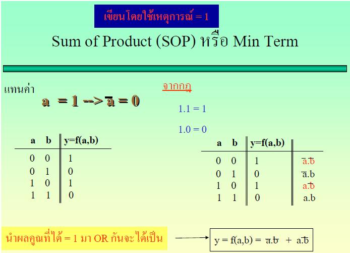
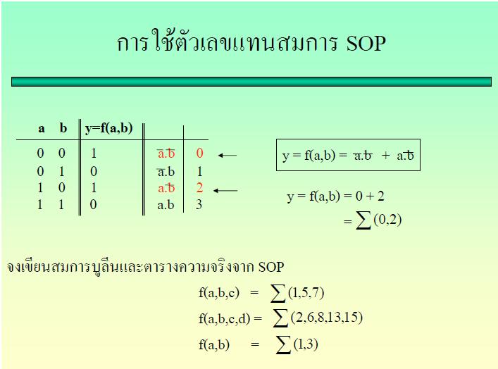
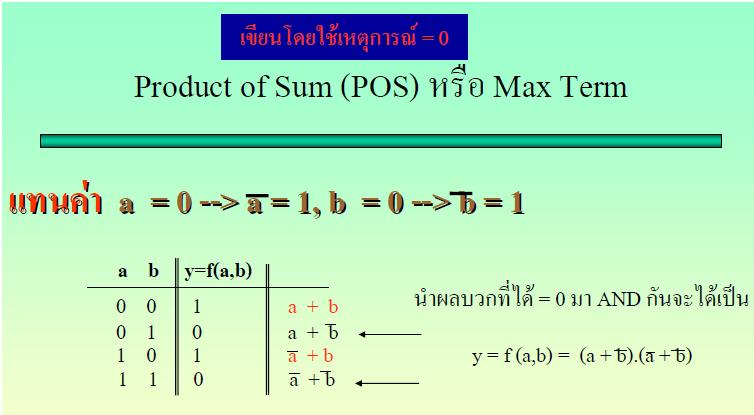
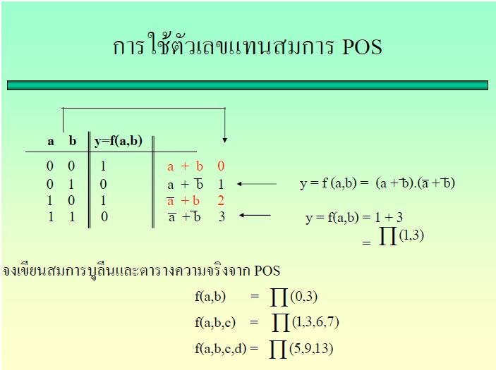
26 SOP/POS Simplify Boolean function to the form canonical, or standardized. For any given Boolean function, there exists a unique standardized form. But, there are different standards that designers use. The two most common are: the sum-of-products (SOP) form and the product-of-sums (POS) form. 26
27 27
28 28
29 Sum-Of-Products form SOP collects of ANDed variables. F (x,y,z) = xy + yz + xyz is in SOP form. F 2 (x,y,z) = xy + x (y + z ) is not in SOP form. Apply the Distributive Law to distribute the x variable in F 2, now F 2 (x,y,z) = xy + xy + xz, which is in SOP form. 29
30 SUM-OF-PRODUCTS FORM Ben Bitdiddle is having a picnic. He won t enjoy it if it rains or if there are ants. Design a circuit that will output TRUE only if Ben enjoys the picnic. 3
31 SUM-OF-PRODUCTS FORM Ants Rain Enjoy E = A B 3
32 32
33 33
34 Product-Of-Sums form POS consists of ORed variables (sum terms) that are ANDed together. F (x,y,z) = (x + y) (x + z )(y + z )(y + z) is in POS form. Ex: from Ben s picnic POS: E = A + R A + R A + R Ants Rain Enjoy 34
35 Simplifying Equations Consider the sum-of-products expression Y = A B + AB: By Theorem T, the equation simplifies to Y = B. Y = A B + AB Y = A + A B Y = B 35

36 Simplifying Equations Consider the sum-of-products expression Y = A B + AB: By Theorem T, the equation simplifies to Y = B. Ex: Minimize Equation A B C + AB C + AB C 36

37 Improved equation minimization A B C + AB C + AB C 37

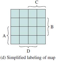
38 K-maps Maurice Karnaugh, 924. Graduated with a bachelor s degree in physics from the City College of New York in 948 and earned a Ph.D. in physics from Yale in 952. Worked at Bell Labs and IBM from 952 to 993 and as a computer science professor at the Polytechnic University of New York from 98 to 999. Karnaugh maps (K-maps) are a graphical method for simplifying Boolean equations. They were invented in 953 by Maurice Karnaugh. K- maps work well for problems with up to four variables. 4
39 K-maps Logic minimization involves combining terms. Two terms containing an implicant P and the true and complementary forms of some variable A are combined to eliminate A: PA+ PA = P. Karnaugh maps make these combinable terms easy to see by putting them next to each other in a grid. 42


40 Karnaugh Maps to Represent Boolean Functions 43

41 K-map of 3 variables 44
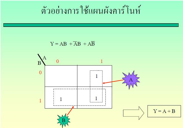
42 Logic Minimization with K-Maps K-maps help us do this simplification graphically by circling s in adjacent squares, as shown in the map. As before, we can use Boolean algebra to minimize equations in SOP form. Y = A B 45
43 Logic Minimization with K-Maps Rules for finding a minimized equation from a K- map are as follows: Use the fewest circles necessary to cover all the s. All the squares in each circle must contain s. Each circle must span a rectangular block that is a power of 2 (i.e.,, 2, or 4) squares in each direction. Each circle should be as large as possible. A circle may wrap around the edges of the K-map. A in a K-map may be circled multiple times if doing so allows fewer circles to be used. 46
44 MINIMIZATION OF A THREE-VARIABLE FUNCTION USING A K-MAP Each circle in the K-map represents a prime implicant, and the dimension of each circle is a power of two (2 and 2 2). 47
45 5

46 53 A B C D Y
47 3.3 Logic Gates We have looked at Boolean functions in abstract terms. In this section, we see that Boolean functions are implemented in digital computer circuits called gates. A gate is an electronic device that produces a result based on two or more input values. In reality, gates consist of one to six transistors, but digital designers think of them as a single unit. Integrated circuits contain collections of gates suited to a particular purpose. 55

48 3.3 Logic Gates The three simplest gates are the AND, OR, and NOT gates. They correspond directly to their respective Boolean operations, as you can see by their truth tables. 56

49 3.3 Logic Gates Another very useful gate is the exclusive OR (XOR) gate. The output of the XOR operation is true only when the values of the inputs differ. Note the special symbol for the XOR operation. 57


50 3.3 Logic Gates NAND and NOR are two very important gates. Their symbols and truth tables are shown at the right. 58

51 3.3 Logic Gates NAND and NOR are known as universal gates because they are inexpensive to manufacture and any Boolean function can be constructed using only NAND or only NOR gates. 59
52 3.3 Logic Gates Gates can have multiple inputs and more than one output. A second output can be provided for the complement of the operation. We ll see more of this later. A Three-Input OR Gate Representing x + y + z Three-Input AND Gate Representing x y z AND Gate with Two Inputs and Two Outputs 6
53 3.3 Logic Gates Drawing schematics, we make them easier to read and debug, generally use the following guidelines: Inputs are on the left side. Outputs are on the right side. Gates should flow from left to right. Drawing with straight wires. Wires always connect at a T junction. A dot where wires cross indicates a connection between the wires. Wires crossing without a dot make no connection. 6
54 3.5 Combinational Circuits We have designed a circuit that implements the Boolean function: This circuit is an example of a combinational logic circuit. Combinational logic circuits produce a specified output (almost) at the instant when input values are applied. 63
55 COMBINATIONAL CIRCUITS Combinational circuit consists of n binary inputs and m binary outputs. As with a gate, a combinational circuit can be defined in three ways: Truth table: For each of the 2 n possible combinations of input signals, the binary value of each of the m output signals is listed. Graphical symbols: The interconnected layout of gates is depicted. Boolean equations: Each output signal is expressed as a Boolean function of its input signals. 64

56 3.5 Combinational Circuits One of the simplest is the half adder to find the sum of two bits. Construction of a half adder by looking at its truth table. f x, y = x y f x, y = xy 65

57 3.5 Combinational Circuits 69

58 3.5 Combinational Circuits 7

59 3.5 Combinational Circuits 7

60 3.5 Combinational Circuits How can we change the half adder shown below to make it a full adder? 73

61 3.5 Combinational Circuits Here s our completed full adder. 74

62 3.5 Combinational Circuits 75

63 3.5 Combinational Circuits 76

64 3.5 Combinational Circuits 77

65 3.5 Combinational Circuits 78
66 3.5 Combinational Circuits 79
67 3.5 Combinational Circuits Just as we combined half adders to make a full adder, Full adders can connected in series, 8 or 6 bits. By replicating the above circuit 6 times, feeding the Carry Out of one circuit into the Carry In of the circuit immediately to its left. This configuration is called a ripple-carry adder. 8


68 3.5 Combinational Circuits Decoders are another important type of combinational circuit. Among other things, they are useful in selecting a memory location according a binary value placed on the address lines of a memory bus. Address decoders with n inputs can select any of 2 n locations. This is a block diagram for a decoder. 82

69 3.5 Combinational Circuits This is what a 2-to-4 decoder looks like on the inside. If x = and y =, which output line is enabled? 83

70 3.5 Combinational Circuits A multiplexer does just the opposite of a decoder. It selects a single output from several inputs. The particular input chosen for output is determined by the value of the multiplexer s control lines. This is a block diagram for a multiplexer. 84

71 3.5 Combinational Circuits This is what a 4-to- multiplexer looks like on the inside. If S = and S =, which input is transferred to the output? 85
72 A Simple Two-Bit ALU 87
73 A Simple Two-Bit ALU 88
74 A Simple Two-Bit ALU 89
75 End of Chapter 3 9
Objectives: 1- Bolean Algebra. Eng. Ayman Metwali
 Objectives: Chapter 3 : 1- Boolean Algebra Boolean Expressions Boolean Identities Simplification of Boolean Expressions Complements Representing Boolean Functions 2- Logic gates 3- Digital Components 4-
Chapter 2. Boolean Expressions:
 Chapter 2 Boolean Expressions: A Boolean expression or a function is an expression which consists of binary variables joined by the Boolean connectives AND and OR along with NOT operation. Any Boolean
Experiment 4 Boolean Functions Implementation
 Experiment 4 Boolean Functions Implementation Introduction: Generally you will find that the basic logic functions AND, OR, NAND, NOR, and NOT are not sufficient to implement complex digital logic functions.
Combinational Logic & Circuits
 Week-I Combinational Logic & Circuits Spring' 232 - Logic Design Page Overview Binary logic operations and gates Switching algebra Algebraic Minimization Standard forms Karnaugh Map Minimization Other
IT 201 Digital System Design Module II Notes
 IT 201 Digital System Design Module II Notes BOOLEAN OPERATIONS AND EXPRESSIONS Variable, complement, and literal are terms used in Boolean algebra. A variable is a symbol used to represent a logical quantity.
CS8803: Advanced Digital Design for Embedded Hardware
 CS883: Advanced Digital Design for Embedded Hardware Lecture 2: Boolean Algebra, Gate Network, and Combinational Blocks Instructor: Sung Kyu Lim (limsk@ece.gatech.edu) Website: http://users.ece.gatech.edu/limsk/course/cs883
Circuit analysis summary
 Boolean Algebra Circuit analysis summary After finding the circuit inputs and outputs, you can come up with either an expression or a truth table to describe what the circuit does. You can easily convert
1. Mark the correct statement(s)
") 1. Mark the correct statement(s) 1.1 A theorem in Boolean algebra: a) Can easily be proved by e.g. logic induction b) Is a logical statement that is assumed to be true, c) Can be contradicted by another
1. Mark the correct statement(s) 1.1 A theorem in Boolean algebra: a) Can easily be proved by e.g. logic induction b) Is a logical statement that is assumed to be true, c) Can be contradicted by another
Chapter 2 Boolean algebra and Logic Gates
 Chapter 2 Boolean algebra and Logic Gates 2. Introduction In working with logic relations in digital form, we need a set of rules for symbolic manipulation which will enable us to simplify complex expressions
Chapter 2 Combinational Logic Circuits
 Logic and Computer Design Fundamentals Chapter 2 Combinational Logic Circuits Part 2 Circuit Optimization Overview Part Gate Circuits and Boolean Equations Binary Logic and Gates Boolean Algebra Standard
Gate-Level Minimization. BME208 Logic Circuits Yalçın İŞLER
 Gate-Level Minimization BME28 Logic Circuits Yalçın İŞLER islerya@yahoo.com http://me.islerya.com Complexity of Digital Circuits Directly related to the complexity of the algebraic expression we use to
Gate Level Minimization Map Method
 Gate Level Minimization Map Method Complexity of hardware implementation is directly related to the complexity of the algebraic expression Truth table representation of a function is unique Algebraically
DIGITAL SYSTEM DESIGN
 DIGITAL SYSTEM DESIGN UNIT I: Introduction to Number Systems and Boolean Algebra Digital and Analog Basic Concepts, Some history of Digital Systems-Introduction to number systems, Binary numbers, Number
Unit-IV Boolean Algebra
 Unit-IV Boolean Algebra Boolean Algebra Chapter: 08 Truth table: Truth table is a table, which represents all the possible values of logical variables/statements along with all the possible results of
Chapter 3. Gate-Level Minimization. Outlines
 Chapter 3 Gate-Level Minimization Introduction The Map Method Four-Variable Map Five-Variable Map Outlines Product of Sums Simplification Don t-care Conditions NAND and NOR Implementation Other Two-Level
Date Performed: Marks Obtained: /10. Group Members (ID):. Experiment # 04. Boolean Expression Simplification and Implementation
:. Experiment # 04. Boolean Expression Simplification and Implementation") Name: Instructor: Engr. Date Performed: Marks Obtained: /10 Group Members (ID):. Checked By: Date: Experiment # 04 Boolean Expression Simplification and Implementation OBJECTIVES: To understand the utilization
Name: Instructor: Engr. Date Performed: Marks Obtained: /10 Group Members (ID):. Checked By: Date: Experiment # 04 Boolean Expression Simplification and Implementation OBJECTIVES: To understand the utilization
Binary logic. Dr.Abu-Arqoub
 Binary logic Binary logic deals with variables like (a, b, c,, x, y) that take on two discrete values (, ) and with operations that assume logic meaning ( AND, OR, NOT) Truth table is a table of all possible
 Get Free notes at Module-I One s Complement: Complement all the bits.i.e. makes all 1s as 0s and all 0s as 1s Two s Complement: One s complement+1 SIGNED BINARY NUMBERS Positive integers (including zero)
Boolean Algebra and Logic Gates
 Boolean Algebra and Logic Gates Binary logic is used in all of today's digital computers and devices Cost of the circuits is an important factor Finding simpler and cheaper but equivalent circuits can
Assignment (3-6) Boolean Algebra and Logic Simplification - General Questions
 Boolean Algebra and Logic Simplification - General Questions") Assignment (3-6) Boolean Algebra and Logic Simplification - General Questions 1. Convert the following SOP expression to an equivalent POS expression. 2. Determine the values of A, B, C, and D that make
Assignment (3-6) Boolean Algebra and Logic Simplification - General Questions 1. Convert the following SOP expression to an equivalent POS expression. 2. Determine the values of A, B, C, and D that make
Boolean algebra. June 17, Howard Huang 1
 Boolean algebra Yesterday we talked about how analog voltages can represent the logical values true and false. We introduced the basic Boolean operations AND, OR and NOT, which can be implemented in hardware
Computer Science. Unit-4: Introduction to Boolean Algebra
 Unit-4: Introduction to Boolean Algebra Learning Objective At the end of the chapter students will: Learn Fundamental concepts and basic laws of Boolean algebra. Learn about Boolean expression and will
SYNERGY INSTITUTE OF ENGINEERING & TECHNOLOGY,DHENKANAL LECTURE NOTES ON DIGITAL ELECTRONICS CIRCUIT(SUBJECT CODE:PCEC4202)
") Lecture No:5 Boolean Expressions and Definitions Boolean Algebra Boolean Algebra is used to analyze and simplify the digital (logic) circuits. It uses only the binary numbers i.e. 0 and 1. It is also called
Lecture No:5 Boolean Expressions and Definitions Boolean Algebra Boolean Algebra is used to analyze and simplify the digital (logic) circuits. It uses only the binary numbers i.e. 0 and 1. It is also called
QUESTION BANK FOR TEST
 CSCI 2121 Computer Organization and Assembly Language PRACTICE QUESTION BANK FOR TEST 1 Note: This represents a sample set. Please study all the topics from the lecture notes. Question 1. Multiple Choice
UNIT-4 BOOLEAN LOGIC. NOT Operator Operates on single variable. It gives the complement value of variable.
 UNIT-4 BOOLEAN LOGIC Boolean algebra is an algebra that deals with Boolean values((true and FALSE). Everyday we have to make logic decisions: Should I carry the book or not?, Should I watch TV or not?
X Y Z F=X+Y+Z
 This circuit is used to obtain the compliment of a value. If X = 0, then X = 1. The truth table for NOT gate is : X X 0 1 1 0 2. OR gate : The OR gate has two or more input signals but only one output
Lecture 4: Implementation AND, OR, NOT Gates and Complement
 EE210: Switching Systems Lecture 4: Implementation AND, OR, NOT Gates and Complement Prof. YingLi Tian Feb. 13, 2018 Department of Electrical Engineering The City College of New York The City University
Computer Organization and Levels of Abstraction
 Computer Organization and Levels of Abstraction Announcements Today: PS 7 Lab 8: Sound Lab tonight bring machines and headphones! PA 7 Tomorrow: Lab 9 Friday: PS8 Today (Short) Floating point review Boolean
BOOLEAN ALGEBRA. Logic circuit: 1. From logic circuit to Boolean expression. Derive the Boolean expression for the following circuits.
 COURSE / CODE DIGITAL SYSTEMS FUNDAMENTAL (ECE 421) DIGITAL ELECTRONICS FUNDAMENTAL (ECE 422) BOOLEAN ALGEBRA Boolean Logic Boolean logic is a complete system for logical operations. It is used in countless
Experiment 3: Logic Simplification
 Module: Logic Design Name:... University no:.. Group no:. Lab Partner Name: Mr. Mohamed El-Saied Experiment : Logic Simplification Objective: How to implement and verify the operation of the logical functions
Chapter 2: Combinational Systems
 Uchechukwu Ofoegbu Chapter 2: Combinational Systems Temple University Adapted from Alan Marcovitz s Introduction to Logic and Computer Design Riddle Four switches can be turned on or off. One is the switch
Digital Logic Design (3)
") Digital Logic Design (3) ENGG1015 1 st Semester, 2010 Dr. Kenneth Wong Dr. Hayden So Department of Electrical and Electronic Engineering Last lecture ll logic functions can be represented as (1) truth
Digital Logic Design (3) ENGG1015 1 st Semester, 2010 Dr. Kenneth Wong Dr. Hayden So Department of Electrical and Electronic Engineering Last lecture ll logic functions can be represented as (1) truth
Simplification of Boolean Functions
 Simplification of Boolean Functions Contents: Why simplification? The Map Method Two, Three, Four and Five variable Maps. Simplification of two, three, four and five variable Boolean function by Map method.
Computer Organization
 Computer Organization (Logic circuits design and minimization) KR Chowdhary Professor & Head Email: kr.chowdhary@gmail.com webpage: krchowdhary.com Department of Computer Science and Engineering MBM Engineering
Chapter 6. Logic Design Optimization Chapter 6
 Chapter 6 Logic Design Optimization Chapter 6 Optimization The second part of our design process. Optimization criteria: Performance Size Power Two-level Optimization Manipulating a function until it is
Standard Forms of Expression. Minterms and Maxterms
 Standard Forms of Expression Minterms and Maxterms Standard forms of expressions We can write expressions in many ways, but some ways are more useful than others A sum of products (SOP) expression contains:
UNIT 2 BOOLEAN ALGEBRA
 UNIT 2 BOOLEN LGEBR Spring 2 2 Contents Introduction Basic operations Boolean expressions and truth tables Theorems and laws Basic theorems Commutative, associative, and distributive laws Simplification
Points Addressed in this Lecture. Standard form of Boolean Expressions. Lecture 4: Logic Simplication & Karnaugh Map
 Points Addressed in this Lecture Lecture 4: Logic Simplication & Karnaugh Map Professor Peter Cheung Department of EEE, Imperial College London Standard form of Boolean Expressions Sum-of-Products (SOP),
Menu. Algebraic Simplification - Boolean Algebra EEL3701 EEL3701. MSOP, MPOS, Simplification
 Menu Minterms & Maxterms SOP & POS MSOP & MPOS Simplification using the theorems/laws/axioms Look into my... 1 Definitions (Review) Algebraic Simplification - Boolean Algebra Minterms (written as m i ):
Bawar Abid Abdalla. Assistant Lecturer Software Engineering Department Koya University
 Logic Design First Stage Lecture No.6 Boolean Algebra Bawar Abid Abdalla Assistant Lecturer Software Engineering Department Koya University Outlines Boolean Operations Laws of Boolean Algebra Rules of
2.1 Binary Logic and Gates
 1 EED2003 Digital Design Presentation 2: Boolean Algebra Asst. Prof.Dr. Ahmet ÖZKURT Asst. Prof.Dr Hakkı T. YALAZAN Based on the Lecture Notes by Jaeyoung Choi choi@comp.ssu.ac.kr Fall 2000 2.1 Binary
ELCT201: DIGITAL LOGIC DESIGN
 ELCT201: DIGITAL LOGIC DESIGN Dr. Eng. Haitham Omran, haitham.omran@guc.edu.eg Dr. Eng. Wassim Alexan, wassim.joseph@guc.edu.eg Lecture 3 Following the slides of Dr. Ahmed H. Madian محرم 1439 ه Winter
Lecture (05) Boolean Algebra and Logic Gates
 Boolean Algebra and Logic Gates") Lecture (05) Boolean Algebra and Logic Gates By: Dr. Ahmed ElShafee ١ Minterms and Maxterms consider two binary variables x and y combined with an AND operation. Since eachv ariable may appear in either
Lecture (05) Boolean Algebra and Logic Gates By: Dr. Ahmed ElShafee ١ Minterms and Maxterms consider two binary variables x and y combined with an AND operation. Since eachv ariable may appear in either
Dr. Chuck Cartledge. 10 June 2015
 Miscellanea Exam #1 Break Exam review 2.1 2.2 2.3 2.4 Break 3 4 Conclusion References CSC-205 Computer Organization Lecture #003 Chapter 2, Sections 2.1 through 4 Dr. Chuck Cartledge 10 June 2015 1/30
Chapter 2. Boolean Algebra and Logic Gates
 Chapter 2. Boolean Algebra and Logic Gates Tong In Oh 1 Basic Definitions 2 3 2.3 Axiomatic Definition of Boolean Algebra Boolean algebra: Algebraic structure defined by a set of elements, B, together
Boolean Algebra. BME208 Logic Circuits Yalçın İŞLER
 Boolean Algebra BME28 Logic Circuits Yalçın İŞLER islerya@yahoo.com http://me.islerya.com 5 Boolean Algebra /2 A set of elements B There exist at least two elements x, y B s. t. x y Binary operators: +
Gate-Level Minimization
 MEC520 디지털공학 Gate-Level Minimization Jee-Hwan Ryu School of Mechanical Engineering Gate-Level Minimization-The Map Method Truth table is unique Many different algebraic expression Boolean expressions may
A graphical method of simplifying logic
 4-5 Karnaugh Map Method A graphical method of simplifying logic equations or truth tables. Also called a K map. Theoretically can be used for any number of input variables, but practically limited to 5
R10. II B. Tech I Semester, Supplementary Examinations, May
 SET - 1 1. a) Convert the following decimal numbers into an equivalent binary numbers. i) 53.625 ii) 4097.188 iii) 167 iv) 0.4475 b) Add the following numbers using 2 s complement method. i) -48 and +31
 Class Subject Code Subject Prepared By Lesson Plan for Time: Lesson. No 1.CONTENT LIST: Introduction to UnitI 2. SKILLS ADDRESSED: Listening I year, 02 sem CS6201 Digital Principles & System Design S.Seedhanadevi
Module -7. Karnaugh Maps
 1 Module -7 Karnaugh Maps 1. Introduction 2. Canonical and Standard forms 2.1 Minterms 2.2 Maxterms 2.3 Canonical Sum of Product or Sum-of-Minterms (SOM) 2.4 Canonical product of sum or Product-of-Maxterms(POM)
Summary. Boolean Addition
 Summary Boolean Addition In Boolean algebra, a variable is a symbol used to represent an action, a condition, or data. A single variable can only have a value of or 0. The complement represents the inverse
Lecture 5. Chapter 2: Sections 4-7
 Lecture 5 Chapter 2: Sections 4-7 Outline Boolean Functions What are Canonical Forms? Minterms and Maxterms Index Representation of Minterms and Maxterms Sum-of-Minterm (SOM) Representations Product-of-Maxterm
Review. EECS Components and Design Techniques for Digital Systems. Lec 05 Boolean Logic 9/4-04. Seq. Circuit Behavior. Outline.
 Review EECS 150 - Components and Design Techniques for Digital Systems Lec 05 Boolean Logic 94-04 David Culler Electrical Engineering and Computer Sciences University of California, Berkeley Design flow
LSN 4 Boolean Algebra & Logic Simplification. ECT 224 Digital Computer Fundamentals. Department of Engineering Technology
 LSN 4 Boolean Algebra & Logic Simplification Department of Engineering Technology LSN 4 Key Terms Variable: a symbol used to represent a logic quantity Compliment: the inverse of a variable Literal: a
Philadelphia University Faculty of Information Technology Department of Computer Science. Computer Logic Design. By Dareen Hamoudeh.
 Philadelphia University Faculty of Information Technology Department of Computer Science Computer Logic Design By Dareen Hamoudeh Dareen Hamoudeh 1 Canonical Forms (Standard Forms of Expression) Minterms
Introduction to Boolean Algebra
 Introduction to Boolean Algebra Boolean algebra which deals with two-valued (true / false or and ) variables and functions find its use in modern digital computers since they too use two-level systems
Austin Herring Recitation 002 ECE 200 Project December 4, 2013
 1. Fastest Circuit a. How Design Was Obtained The first step of creating the design was to derive the expressions for S and C out from the given truth tables. This was done using Karnaugh maps. The Karnaugh
Combinational Logic Circuits
 Chapter 2 Combinational Logic Circuits J.J. Shann (Slightly trimmed by C.P. Chung) Chapter Overview 2-1 Binary Logic and Gates 2-2 Boolean Algebra 2-3 Standard Forms 2-4 Two-Level Circuit Optimization
MODULE 5 - COMBINATIONAL LOGIC
 Introduction to Digital Electronics Module 5: Combinational Logic 1 MODULE 5 - COMBINATIONAL LOGIC OVERVIEW: For any given combination of input binary bits or variables, the logic will have a specific
Computer Engineering Chapter 3 Boolean Algebra
 Computer Engineering Chapter 3 Boolean Algebra Hiroaki Kobayashi 5/30/2011 Ver. 06102011 5/30/2011 Computer Engineering 1 Agenda in Chapter 3 What is Boolean Algebra Basic Boolean/Logical Operations (Operators)
B.Tech II Year I Semester (R13) Regular Examinations December 2014 DIGITAL LOGIC DESIGN
 Regular Examinations December 2014 DIGITAL LOGIC DESIGN") B.Tech II Year I Semester () Regular Examinations December 2014 (Common to IT and CSE) (a) If 1010 2 + 10 2 = X 10, then X is ----- Write the first 9 decimal digits in base 3. (c) What is meant by don
B.Tech II Year I Semester () Regular Examinations December 2014 (Common to IT and CSE) (a) If 1010 2 + 10 2 = X 10, then X is ----- Write the first 9 decimal digits in base 3. (c) What is meant by don
Bawar Abid Abdalla. Assistant Lecturer Software Engineering Department Koya University
 Logic Design First Stage Lecture No.5 Boolean Algebra Bawar Abid Abdalla Assistant Lecturer Software Engineering Department Koya University Boolean Operations Laws of Boolean Algebra Rules of Boolean Algebra
Introduction to Boolean Algebra
 Introduction to Boolean Algebra Boolean algebra which deals with two-valued (true / false or and ) variables and functions find its use in modern digital computers since they too use two-level systems
Review: Standard forms of expressions
 Karnaugh maps Last time we saw applications of Boolean logic to circuit design. The basic Boolean operations are AND, OR and NOT. These operations can be combined to form complex expressions, which can
Combinational Logic Circuits Part III -Theoretical Foundations
 Combinational Logic Circuits Part III -Theoretical Foundations Overview Simplifying Boolean Functions Algebraic Manipulation Karnaugh Map Manipulation (simplifying functions of 2, 3, 4 variables) Systematic
ELCT201: DIGITAL LOGIC DESIGN
 ELCT201: DIGITAL LOGIC DESIGN Dr. Eng. Haitham Omran, haitham.omran@guc.edu.eg Dr. Eng. Wassim Alexan, wassim.joseph@guc.edu.eg Lecture 3 Following the slides of Dr. Ahmed H. Madian ذو الحجة 1438 ه Winter
Code No: R Set No. 1
 Code No: R059210504 Set No. 1 II B.Tech I Semester Regular Examinations, November 2007 DIGITAL LOGIC DESIGN ( Common to Computer Science & Engineering, Information Technology and Computer Science & Systems
Designing Computer Systems Boolean Algebra
 Designing Computer Systems Boolean Algebra 08:34:45 PM 4 June 2013 BA-1 Scott & Linda Wills Designing Computer Systems Boolean Algebra Programmable computers can exhibit amazing complexity and generality.
Boolean Algebra. P1. The OR operation is closed for all x, y B x + y B
 Boolean Algebra A Boolean Algebra is a mathematical system consisting of a set of elements B, two binary operations OR (+) and AND ( ), a unary operation NOT ('), an equality sign (=) to indicate equivalence
Combinational Circuits Digital Logic (Materials taken primarily from:
 Combinational Circuits Digital Logic (Materials taken primarily from: http://www.facstaff.bucknell.edu/mastascu/elessonshtml/eeindex.html http://www.cs.princeton.edu/~cos126 ) Digital Systems What is a
Boolean Algebra & Digital Logic
 Boolean Algebra & Digital Logic Boolean algebra was developed by the Englishman George Boole, who published the basic principles in the 1854 treatise An Investigation of the Laws of Thought on Which to
Chapter 2 Combinational
 Computer Engineering 1 (ECE290) Chapter 2 Combinational Logic Circuits Part 2 Circuit Optimization HOANG Trang 2008 Pearson Education, Inc. Overview Part 1 Gate Circuits and Boolean Equations Binary Logic
Ch. 5 : Boolean Algebra &
 Ch. 5 : Boolean Algebra & Reduction elektronik@fisika.ui.ac.id Objectives Should able to: Write Boolean equations for combinational logic applications. Utilize Boolean algebra laws and rules for simplifying
Gate Level Minimization
 Gate Level Minimization By Dr. M. Hebaishy Digital Logic Design Ch- Simplifying Boolean Equations Example : Y = AB + AB Example 2: = B (A + A) T8 = B () T5 = B T Y = A(AB + ABC) = A (AB ( + C ) ) T8 =
Computer Organization and Levels of Abstraction
 Computer Organization and Levels of Abstraction Announcements PS8 Due today PS9 Due July 22 Sound Lab tonight bring machines and headphones! Binary Search Today Review of binary floating point notation
Combinational Logic Circuits
 Chapter 3 Combinational Logic Circuits 12 Hours 24 Marks 3.1 Standard representation for logical functions Boolean expressions / logic expressions / logical functions are expressed in terms of logical
CprE 281: Digital Logic
 CprE 28: Digital Logic Instructor: Alexander Stoytchev http://www.ece.iastate.edu/~alexs/classes/ Minimization CprE 28: Digital Logic Iowa State University, Ames, IA Copyright Alexander Stoytchev Administrative
Henry Lin, Department of Electrical and Computer Engineering, California State University, Bakersfield Lecture 7 (Digital Logic) July 24 th, 2012
 July 24 th, 2012") Henry Lin, Department of Electrical and Computer Engineering, California State University, Bakersfield Lecture 7 (Digital Logic) July 24 th, 2012 1 Digital vs Analog Digital signals are binary; analog
Henry Lin, Department of Electrical and Computer Engineering, California State University, Bakersfield Lecture 7 (Digital Logic) July 24 th, 2012 1 Digital vs Analog Digital signals are binary; analog
Introduction to Computer Architecture
 Boolean Operators The Boolean operators AND and OR are binary infix operators (that is, they take two arguments, and the operator appears between them.) A AND B D OR E We will form Boolean Functions of
EEE130 Digital Electronics I Lecture #4_1
 EEE130 Digital Electronics I Lecture #4_1 - Boolean Algebra and Logic Simplification - By Dr. Shahrel A. Suandi 4-6 Standard Forms of Boolean Expressions There are two standard forms: Sum-of-products form
R.M.D. ENGINEERING COLLEGE R.S.M. Nagar, Kavaraipettai
 L T P C R.M.D. ENGINEERING COLLEGE R.S.M. Nagar, Kavaraipettai- 601206 DEPARTMENT OF ELECTRONICS AND COMMUNICATION ENGINEERING EC8392 UNIT - I 3 0 0 3 OBJECTIVES: To present the Digital fundamentals, Boolean
Contents. Chapter 3 Combinational Circuits Page 1 of 34
 Chapter 3 Combinational Circuits Page of 34 Contents Contents... 3 Combinational Circuits... 2 3. Analysis of Combinational Circuits... 2 3.. Using a Truth Table... 2 3..2 Using a Boolean unction... 4
COMP combinational logic 1 Jan. 18, 2016
 In lectures 1 and 2, we looked at representations of numbers. For the case of integers, we saw that we could perform addition of two numbers using a binary representation and using the same algorithm that
Gate-Level Minimization
 Gate-Level Minimization ( 范倫達 ), Ph. D. Department of Computer Science National Chiao Tung University Taiwan, R.O.C. Fall, 2011 ldvan@cs.nctu.edu.tw http://www.cs.nctu.edu.tw/~ldvan/ Outlines The Map Method
CS February 17
 Discrete Mathematics CS 26 February 7 Equal Boolean Functions Two Boolean functions F and G of degree n are equal iff for all (x n,..x n ) B, F (x,..x n ) = G (x,..x n ) Example: F(x,y,z) = x(y+z), G(x,y,z)
2008 The McGraw-Hill Companies, Inc. All rights reserved.
 28 The McGraw-Hill Companies, Inc. All rights reserved. 28 The McGraw-Hill Companies, Inc. All rights reserved. All or Nothing Gate Boolean Expression: A B = Y Truth Table (ee next slide) or AB = Y 28
Gate-Level Minimization. section instructor: Ufuk Çelikcan
 Gate-Level Minimization section instructor: Ufuk Çelikcan Compleity of Digital Circuits Directly related to the compleity of the algebraic epression we use to build the circuit. Truth table may lead to
6. Combinational Circuits. Building Blocks. Digital Circuits. Wires. Q. What is a digital system? A. Digital: signals are 0 or 1.
 Digital Circuits 6 Combinational Circuits Q What is a digital system? A Digital: signals are or analog: signals vary continuously Q Why digital systems? A Accurate, reliable, fast, cheap Basic abstractions
UNIT II. Circuit minimization
 UNIT II Circuit minimization The complexity of the digital logic gates that implement a Boolean function is directly related to the complexity of the algebraic expression from which the function is implemented.
COMBINATIONAL LOGIC CIRCUITS
 COMBINATIONAL LOGIC CIRCUITS 4.1 INTRODUCTION The digital system consists of two types of circuits, namely: (i) Combinational circuits and (ii) Sequential circuits A combinational circuit consists of logic
Combinational Circuits
 Combinational Circuits Q. What is a combinational circuit? A. Digital: signals are or. A. No feedback: no loops. analog circuits: signals vary continuously sequential circuits: loops allowed (stay tuned)
Chapter Three. Digital Components
 Chapter Three 3.1. Combinational Circuit A combinational circuit is a connected arrangement of logic gates with a set of inputs and outputs. The binary values of the outputs are a function of the binary
Boolean Logic CS.352.F12
 Boolean Logic CS.352.F12 Boolean Algebra Boolean Algebra Mathematical system used to manipulate logic equations. Boolean: deals with binary values (True/False, yes/no, on/off, 1/0) Algebra: set of operations
DKT 122/3 DIGITAL SYSTEM 1
 Company LOGO DKT 122/3 DIGITAL SYSTEM 1 BOOLEAN ALGEBRA (PART 2) Boolean Algebra Contents Boolean Operations & Expression Laws & Rules of Boolean algebra DeMorgan s Theorems Boolean analysis of logic circuits
6.1 Combinational Circuits. George Boole ( ) Claude Shannon ( )
 Claude Shannon ( )") 6. Combinational Circuits George Boole (85 864) Claude Shannon (96 2) Signals and Wires Digital signals Binary (or logical ) values: or, on or off, high or low voltage Wires. Propagate digital signals
6. Combinational Circuits George Boole (85 864) Claude Shannon (96 2) Signals and Wires Digital signals Binary (or logical ) values: or, on or off, high or low voltage Wires. Propagate digital signals
Code No: R Set No. 1
 Code No: R059210504 Set No. 1 II B.Tech I Semester Supplementary Examinations, February 2007 DIGITAL LOGIC DESIGN ( Common to Computer Science & Engineering, Information Technology and Computer Science
BOOLEAN ALGEBRA. 1. State & Verify Laws by using :
 BOOLEAN ALGEBRA. State & Verify Laws by using :. State and algebraically verify Absorption Laws. (2) Absorption law states that (i) X + XY = X and (ii) X(X + Y) = X (i) X + XY = X LHS = X + XY = X( + Y)
Variable, Complement, and Literal are terms used in Boolean Algebra.
 We have met gate logic and combination of gates. Another way of representing gate logic is through Boolean algebra, a way of algebraically representing logic gates. You should have already covered the
Propositional Calculus. Math Foundations of Computer Science
 Propositional Calculus Math Foundations of Computer Science Propositional Calculus Objective: To provide students with the concepts and techniques from propositional calculus so that they can use it to