Patient Set-ups and Tumor Localizations
|
|
|
- Ralph Riley
- 5 years ago
- Views:
Transcription
1 Patient Set-ups and Tumor Localizations Amy S. Harrison Patient Positioning Prior to starting any localization or simulation procedure patients need to be positioned and immobilized Patients disease location and physical limitations must be taken into consideration
2 Patient Alignment Reproducible positioning of the entire patient, not just the treatment region is imperative A small angle change of the patient on the table can represent a significant change in the delivered treatment Exaggerated Patient Position Shift

3 Patient Positioning-Brain/H+N Immobilized by aquaplast masks over the head alone/ or head and shoulders The need for a bite block should be addressed Head holders should be selected for patient comfort and extension of neck Indexing of immobilization improves reproducibility of set up Head Immobilization
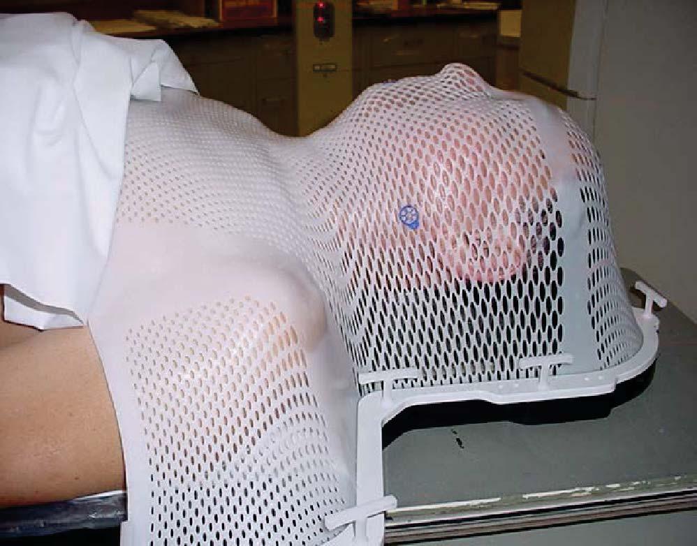

4 Head Immobilization Full Set Up Photo H+N Case

5 Lung Alpha cradle Arms up? Arms down? ABC device Abdominal Compression Device Leg immobilization-rubber band, plastic foot holder, angle sponge? Will it clear CT/MRI bore Stereotactic Lung

6 Lung Lung

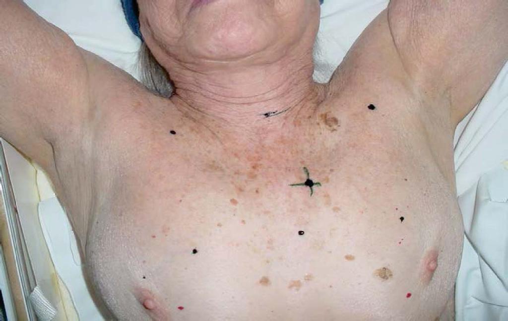
7 Breast Immobilization Alpha cradle or wing board Opposite arm immobilized how? ABC device Leg immobilization-rubber band, plastic foot holder, angle sponge? Will it clear CT/MRI bore Breast
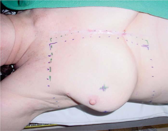


8 Breast Breast

9 Breast Prostate/Pelvis Pelvis-full aquaplast, alpha cradle or nothing Legs on angle sponge or flat Feet rubber bands or foot holder Arms?


10 Prostate/Pelvis Prostate/Pelvis

11 Prone Rectum Belly board, angle sponge? Feet? Patient on pillow or not? Rectum/Prone

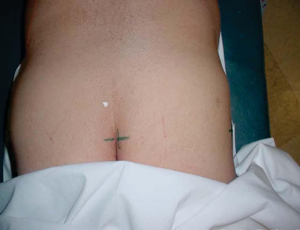
12 Prone Rectum Prone Rectum
13 Immobilization vs. High Tech IGRT- cone beam or fiducials Tomotherapy Cyber Knife ExacTrac Localization Procedure where the target and critical structures are delineated with reference to the patient s external surface


14 Classical Localization The patient s external surface was attained by using solder wire or plaster of paris This surface was then drawn on a piece of paper Or pantograph 2D Contours


15 Classical Localization Tumor and critical structures were transcribed from hard copy CT studies or MD demarcation on the orthogonal films taken at the time of localization 2D Contours
16 2D Contours 2D Contours
17 2D Contours and Coordinates Simulation A procedure where the planned fields are verified by shooting diagnostic quality films in the simulator (a machine which mimics the geometry of the treatment unit))
18 The CT Simulator The advent of the CTsim dramatically modified the simulation and localization procedures. Localization could now be done at the time of Ctsim Target delineation was truly 3D Precision and accuracy greatly improved The Ct Sim For Patient Marking An integral functionality of the CT Simulator unit is the capability of placing reference marks on the patient to indicate the isocenter for the treatment fields. 1) Reference marks can be placed near the isocenter of the patient. This is an estimate of the final isocenter and does not require extensive contouring. The isocenter is found through a series of exact moves from the reference marks. 2) After detailed contouring, the final isocenter position is marked on the patient.

19 XIO FocalSim 3D Contours and Coordinates

20 3D Contours and Coordinates 3D CT Images Scanned = Transverse/ Axial Generated= Sagittal Generated= Coronal

21 Virtual Simulations Ct Sims allowed the verification simulation process to become virtual Traditional 2D fields could be set in the 3D dataset The patient could be scanned, marked and sent home given an appointment time for treatment XIO Focalsim
22 Advantages of the CT Simulator Virtual simulation/verification process Generating a new/conedown plan can be accomplished without having to bring the patient back for another simulation. Disadvantages of the CT Simulator Structure motion cannot easily be detected with a CT Simulator. Excluding 4D scanners. CT doughnut is usually restricted to 70-80cm in diameter.this can limit the patient's position for some treatments. For example, placing the patient's arms up can be a problem.
23 CT Simulators CT scan process allows 3D volumetric information to be gathered and carries out simulation as a digital process. Relies on construction of digitally reconstructed radiographs QA of CT-Simulators
24 HISTORICALLY: QA of CT Scanners CT scans for treatment planning are often done with a flat top insert on the CT table to reproduce the radiation therapy treatment couch top. laser system mimicking that used on the simulation and treatment units should be mounted in the CT suite and the alignment of the lasers should be checked daily. Such a system is an integral component for relating the patient s position during CT with that on the simulation and treatment machines. The correlation of CT numbers with electron densities and the variation of CT numbers with position and phantom size should be determined. Since this correlation is a function of the quality of the x-ray beam, it should be checked yearly. In addition, the CT scanner should be checked for image quality and other parameters described in the QA protocol provided by the manufacturer. QA of CT scanners (AAPM, 1977) Quality assurance for computed-tomography simulators and the computed tomographysimulation process: Report of the AAPM Radiation Therapy Committee Task Group No. 66
25 AAPM Task Group #66 Mechanicals Common Sense Applies +/- 2mm most items Table indexing and motions are 1mm
26 Spatial integrity QA goals: CT-simulation images should accurately reproduce true patient anatomy within 1 mm without spatial distortions in the entire scan field. This should be verified for both head and body scan protocols using a phantom of known dimensions. Spatial resolution Characterizes the imaging system s ability to distinguish between two very small objects placed closely together. Spatial resolution is frequently referred to as high contrast resolution


27 High contrast resolution most commonly measured using either a resolution pattern ~line pair phantom with a range of spatial frequencies!, or by the modulation transfer function ~MTF! method. The line pair pattern in following slide ranges in frequency from 1 lp/cm to 21 lp/cm. Note the Bead in the phantom phantom which is a high-density, tungsten carbide bead which is used to create an impulse, or point source, from which the MTF can be calculated. Manufacturers often specify the limiting spatial resolution at the 5% or lower point on the MTF curve. The limiting spatial resolution ~lp/cm measured with MTF, and specified at the 5%value, is typically higher than the resolution that can be observed with a line pair phantom. CT Scanner Line Pairs Slide Images from


28 MTF Plots the contrast against the resolution Completely characterizes the high-contrast resolution of the scan mode Slide Images from High Contrast Low Contrast

29 Contrast resolution Contrast resolution can be defined as the CTscanner s ability to distinguish relatively large objects which differ only slightly in density from background. QA goals: Quality assurance should demonstrate that the CT-scanner meets or exceeds manufacturer specifications for low contrast resolution Sensitivity and Profiles Slice sensitivity is a curve showing the effect of broadening of the CT slice Thickness along patient in helical CT Slide Images from
30 Image Performance When referencing manufacturers specifications tolerances are set to the acceptance criteria and can then be called the baseline measurement CT Sim Software: Image input test Structure delineation (contouring) Multimodality image registration Machine definition Isocenter calculation and movement Image reconstruction Evaluation of digitally reconstructed radiographs
31 Evaluation of digitally reconstructed radiographs Spatial and contrast resolution: It is generally understood that smaller slice thickness and spacing produces better spatial resolution DRRs. Geometric and spatial accuracy: Magnification should be within 1 mm of expected. Spatial errors ~e.g., collimator, table rotation, incorrect jaw setting, etc.! can also cause errors which may not be detected from patient port films. The QA for the CTsimulation process should include evaluation of DRR geometric errors. Hardcopy quality: Printing of standard test patterns and comparison with baseline data can reveal potential problems EVALUATION OF THE CT-SIMULATION PROCESS Overall process tests: Patient positioning and immobilization, Scan limits, Scan protocol, Contrast, Special considerations and instructions, Data acquisition, Localization/marking, Virtual simulation, DRR and setup documentation
32 DRR Digitally constructed images from the 3D dataset Generated with the same geometry as a divergent radiograph produced with a point source of radiation. Created by combining the influence of the CT pixel elements from a CT dataset along divergent ray lines. DRR Tools Computer generated films allow selection of the bony anatomy needing to be imaged DRR s can be adjusted by using a window/leveling tool Drr s can be generated for any treatment angle there are no collision issues in virtual space


33 DRR Region of Interest DRR Quality # of Slices CT # accuracy Slice thickness Scan technique used Reconstruction algorithm
34 DRR Artifacts Contrast Agents Prosthesis Respiratory Motion Anatomy (inadequate scan technique) Scanner Types First Generation: Translate/Rotate Second Generation: Translate/Rotate Third Generation: Rotate/Rotate Fourth Generation: Rotate/Fixed Spiral CT (3rd or 4th generation type) Cine Ct


35 Retrieved from
36 Single Slice Spiral CT Pitch Pitch = (table increment distance (mm) per 360 gantry rotation) / slice thickness (mm) slice thickness 5mm, table motion 7.5mm/rotation, Pitch = 1.5 Pitch of 1=adjacent rotations Pitch>1 = gaps between x-ray beams from adjacent rotations Multi Slice Spiral CT Beam Pitch = (table increment distance (mm) per 360 gantry rotation) / slice thickness (mm) X n (number of slices acquired) slice thickness 5mm, on a 4 slice scanner, table motion 15 mm/rotation Beam pitch = 15 / 4 x 5 =.75
37 Slice Sensitivity Image Reconstruction Iterative Solvers-slower but better when missing data Analytic Methods-Fourier Analysis Filtered back projection Can begin with first data acquired Can be hard wired into system (speed)

38 Image Reconstruction Ramp Filters
39 Cone Beam CT Planar images are acquired with the kv or MV imaging system. Volumetric image reconstruction is performed Houndsfield Units The relative attenuation coefficient ( ) is usually expressed in HU aka CT numbers HU= 1000 x ( x - water )/ water where x is the attenuation coefficient of material x and water is the attenuation coefficient of water
40 HU vs CT CT Numbers are based on manufacturer constant K CT = K x ( x - water )/ water where x is the attenuation coefficient of material x and water is the attenuation coefficient of water Houndsfield Units

41 Window and Level Lung Windows


42 Soft Tissue Windows Relation of FOV, Matrix Size and Pixels

 and with metal artifact reduction")
43 Beam Hardening Barrett J F, Keat N Radiographics 2004;24: Figure 15b. CT images of a patient with metal spine implants, reconstructed without any correction (a) and with metal artifact reduction (b) by Radiological Society of North America


44 Partial Volume Effects Motion
45 Typical Doses Magnetic Resonance Imaging Study of the magnetic properties of the nucleus Nuclei under a strong magnetic field absorb energy which is then released at a later time This time period is unique to the nuclei and surrounding area T1 and T2 are time values

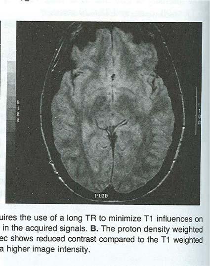

46 T1 Images T2 Images
47 MRI: The Pros and Cons Pros: Cons: 1. Better soft tissue imaging 2. Multiplane imaging 3. Data unaffected by bones 1. Image distortion 2. No electron density information-cannot be used for dose calculation w/o CT fusion Positron Emission Tomography Functional images: provides information about physiology instead of anatomy Generates transverse images depicting the distribution of positron emitting nuclides MUST be fused with CT images for treatment planning
48 PET Continued When positron annihilates it emits two 511keV photons in nearly opposite directions; these photons interact with the annihilation coincidence detectors and obtain projections of the activity distributed in the patient Image Fusion 4 Techniques 1. Coordinate transformation Fiducial markers/stereotactic frames 2. Surfaced based registration The surfaces of one or more structures are matched and used for computation and minimizing mismatch of the data set. Useful with skull or pelvis.
49 Image Fusion Continued 3. Image Based Registration Grayscale data is used directly to measure mismatch or similarity between datasets (Mutual Informationmeasurement of redundant data) 4. Interactive Techniques Effective in cases with a limited number of degrees of freedom. Verified visually. Can be used to limit the amount of time needed for calculation based fusion. Fusion Once the datasets are fused structures may be mapped from one dataset to another So target volumes may be delineated on an MRI or PET and transferred to CT data for planning


50 MRI/CT Mutual Information MRI/CT Grayscale Visual Check
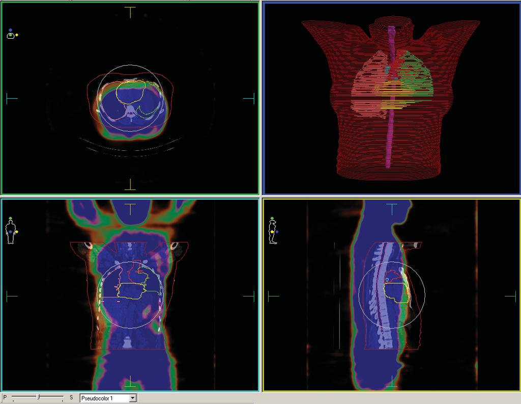

51 PET/CT Pre-Fusion PET/Ct Post Fusion


52 What is the fourth dimension? Time and therefore motion 4D CT Scan Measures Lung Cancer Motion


 4D thoracic CT imaging")
53 4D CT scan GE Lightspeed with Varian RPM system captures repeat CT images at each couch position during respiratory cycle CT sample interval images/slice position Pan et al, Med Phys 31, 333 (2004); Med Phys 34, 4499 (2007) 4D thoracic CT imaging Vedam et al PMB 2003
54 What use are 4D CT scans? Determine tumor motion/screening Motion inclusive treatment Respiratory gated treatment 4D radiotherapy All video images on 4d treatment techniques are curtesy of Paul Keall 4D CT in radiotherapy Scenario 1: No respiratory motion management devices


55 Inhale & exhale CT phases Tumor Motion encompassing volume Tumor Exhale Inhale Motion inclusive treatment
 Create PTV Plan and treat with gating Gating tumor tumor tumor Beam ON Beam OFF")
56 Scenario 2: Respiratory gating Acquire 4D CT Select respiratory phase(s) Delineate GTV/CTV on chosen phase(s) Create PTV Plan and treat with gating Gating tumor tumor tumor Beam ON Beam OFF Beam ON

57 Respiratory gated treatment Accuray Works in Progress 4D Radiotherapy Dynamic MLC motion to match target motion Dynamic table motion
58 Things to Chew Over Dynamic delivery will require planning of each phase of respiration What will the QA of the delivery devices look like 2010 question- What if the patient sneezes?!? 2011 answer- 4D conebeam D CBCT Elekta XVI 4.5 Symmetry Slow gantry motions about 3 minutes for a 200 degree rotation Software auto correlates data by surface or internal motions Motion induced blur of structures reduced Streaking artifacts common-more visible in axial images Have had patients not treated due variations in respirations usually caused by coughing from illness-returned next day with cough suppressant


59 Sonke et al, Med Phys 32, 1176 (2005) 4D-CBCT Streaking Streaking artifacts can be Reduced with slower gantry Rotations = increased times Li & Xing, IJROPBP 67, 1211, 2007


60 4D CBCT Pre-Treatment Verification Thank you so much for your time and consideration Good luck on all your future physics endeavors
Brilliance CT Big Bore.
 1 2 2 There are two methods of RCCT acquisition in widespread clinical use: cine axial and helical. In RCCT with cine axial acquisition, repeat CT images are taken each couch position while recording respiration.
7/31/2011. Learning Objective. Video Positioning. 3D Surface Imaging by VisionRT
 CLINICAL COMMISSIONING AND ACCEPTANCE TESTING OF A 3D SURFACE MATCHING SYSTEM Hania Al-Hallaq, Ph.D. Assistant Professor Radiation Oncology The University of Chicago Learning Objective Describe acceptance
Image Quality Assessment and Quality Assurance of Advanced Imaging Systems for IGRT. AAPM Penn-Ohio Chapter Sep 25, 2015 Soyoung Lee, PhD
 Image Quality Assessment and Quality Assurance of Advanced Imaging Systems for IGRT AAPM Penn-Ohio Chapter Sep 25, 2015 Soyoung Lee, PhD 1 Outline q Introduction q Imaging performances in 4D-CBCT Image
Image Guidance and Beam Level Imaging in Digital Linacs
 Image Guidance and Beam Level Imaging in Digital Linacs Ruijiang Li, Ph.D. Department of Radiation Oncology Stanford University School of Medicine 2014 AAPM Therapy Educational Course Disclosure Research
8/3/2016. Image Guidance Technologies. Introduction. Outline
 8/3/26 Session: Image Guidance Technologies and Management Strategies Image Guidance Technologies Jenghwa Chang, Ph.D.,2 Department of Radiation Medicine, Northwell Health 2 Hofstra Northwell School of
C a t p h a n / T h e P h a n t o m L a b o r a t o r y
 C a t p h a n 5 0 0 / 6 0 0 T h e P h a n t o m L a b o r a t o r y C a t p h a n 5 0 0 / 6 0 0 Internationally recognized for measuring the maximum obtainable performance of axial, spiral and multi-slice
1. Learn to incorporate QA for surface imaging
 Hania Al-Hallaq, Ph.D. Assistant Professor Radiation Oncology The University of Chicago ***No disclosures*** 1. Learn to incorporate QA for surface imaging into current QA procedures for IGRT. 2. Understand
Image Acquisition Systems
 Image Acquisition Systems Goals and Terminology Conventional Radiography Axial Tomography Computer Axial Tomography (CAT) Magnetic Resonance Imaging (MRI) PET, SPECT Ultrasound Microscopy Imaging ITCS
Design and performance characteristics of a Cone Beam CT system for Leksell Gamma Knife Icon
 Design and performance characteristics of a Cone Beam CT system for Leksell Gamma Knife Icon WHITE PAPER Introduction Introducing an image guidance system based on Cone Beam CT (CBCT) and a mask immobilization
Digital Tomosynthesis for Target Localization
 Digital Tomosynthesis for Target Localization Fang-Fang Yin, Devon Godfrey, Lei Ren Jacqueline Maurer, Jackie Q-L Wu Duke University Medical Center Acknowledgements Duke Radiation Oncology faculty and
Automated Image Analysis Software for Quality Assurance of a Radiotherapy CT Simulator
 Automated Image Analysis Software for Quality Assurance of a Radiotherapy CT Simulator Andrew J Reilly Imaging Physicist Oncology Physics Edinburgh Cancer Centre Western General Hospital EDINBURGH EH4
Financial disclosure. Onboard imaging modality for IGRT
 Tetrahedron Beam Computed Tomography Based On Multi-Pixel X- Ray Source and Its Application in Image Guided Radiotherapy Tiezhi Zhang, Ph.D. Advanced X-ray imaging Lab Financial disclosure Patent royalty
Tomotherapy Physics. Machine Twinning and Quality Assurance. Emilie Soisson, MS
 Tomotherapy Physics Machine Twinning and Quality Assurance Emilie Soisson, MS Tomotherapy at UW- Madison Treating for nearly 5 years Up to ~45 patients a day on 2 tomo units Units twinned to facilitate
Shadow casting. What is the problem? Cone Beam Computed Tomography THE OBJECTIVES OF DIAGNOSTIC IMAGING IDEAL DIAGNOSTIC IMAGING STUDY LIMITATIONS
 Cone Beam Computed Tomography THE OBJECTIVES OF DIAGNOSTIC IMAGING Reveal pathology Reveal the anatomic truth Steven R. Singer, DDS srs2@columbia.edu IDEAL DIAGNOSTIC IMAGING STUDY Provides desired diagnostic
Optimization of CT Simulation Imaging. Ingrid Reiser Dept. of Radiology The University of Chicago
 Optimization of CT Simulation Imaging Ingrid Reiser Dept. of Radiology The University of Chicago Optimization of CT imaging Goal: Achieve image quality that allows to perform the task at hand (diagnostic
Artefakt-resistente Bewegungsschätzung für die bewegungskompensierte CT
 Artefakt-resistente Bewegungsschätzung für die bewegungskompensierte CT Marcus Brehm 1,2, Thorsten Heußer 1, Pascal Paysan 3, Markus Oehlhafen 3, and Marc Kachelrieß 1,2 1 German Cancer Research Center
MEDICAL EQUIPMENT: COMPUTED TOMOGRAPHY. Prof. Yasser Mostafa Kadah
 MEDICAL EQUIPMENT: COMPUTED TOMOGRAPHY Prof. Yasser Mostafa Kadah www.k-space.org Recommended Textbook X-Ray Computed Tomography in Biomedical Engineering, by Robert Cierniak, Springer, 211 Computed Tomography
3/27/2012 WHY SPECT / CT? SPECT / CT Basic Principles. Advantages of SPECT. Advantages of CT. Dr John C. Dickson, Principal Physicist UCLH
 3/27/212 Advantages of SPECT SPECT / CT Basic Principles Dr John C. Dickson, Principal Physicist UCLH Institute of Nuclear Medicine, University College London Hospitals and University College London john.dickson@uclh.nhs.uk
Lucy Phantom MR Grid Evaluation
 Lucy Phantom MR Grid Evaluation Anil Sethi, PhD Loyola University Medical Center, Maywood, IL 60153 November 2015 I. Introduction: The MR distortion grid, used as an insert with Lucy 3D QA phantom, is
Ch. 4 Physical Principles of CT
 Ch. 4 Physical Principles of CT CLRS 408: Intro to CT Department of Radiation Sciences Review: Why CT? Solution for radiography/tomography limitations Superimposition of structures Distinguishing between
Introduction. Quality Assurance for Image- Guided Radiation Therapy. Justification for IGRT. Image-Guided Radiation Therapy
 Introduction Quality Assurance for Image- Guided Radiation Therapy Jean-Pierre Bissonnette, Ph.D., MCCPM Princess Margaret Hospital, Toronto, Canada IGRT What is it? Rationale Equipment Quality Assurance
TomoTherapy Related Projects. An image guidance alternative on Tomo Low dose MVCT reconstruction Patient Quality Assurance using Sinogram
 TomoTherapy Related Projects An image guidance alternative on Tomo Low dose MVCT reconstruction Patient Quality Assurance using Sinogram Development of A Novel Image Guidance Alternative for Patient Localization
Digital Image Processing
 Digital Image Processing SPECIAL TOPICS CT IMAGES Hamid R. Rabiee Fall 2015 What is an image? 2 Are images only about visual concepts? We ve already seen that there are other kinds of image. In this lecture
Automated Quality Assurance for Image-Guided Radiation Therapy
 JOURNAL OF APPLIED CLINICAL MEDICAL PHYSICS, VOLUME 10, NUMBER 1, WINTER 2009 Automated Quality Assurance for Image-Guided Radiation Therapy Eduard Schreibmann, a Eric Elder, Tim Fox Department of Radiation
ADVANCING CANCER TREATMENT
 The RayPlan treatment planning system makes proven, innovative RayStation technology accessible to clinics that need a cost-effective and streamlined solution. Fast, efficient and straightforward to use,
CT Basics Principles of Spiral CT Dose. Always Thinking Ahead.
 1 CT Basics Principles of Spiral CT Dose 2 Who invented CT? 1963 - Alan Cormack developed a mathematical method of reconstructing images from x-ray projections Sir Godfrey Hounsfield worked for the Central
Optical Guidance. Sanford L. Meeks. July 22, 2010
 Optical Guidance Sanford L. Meeks July 22, 2010 Optical Tracking Optical tracking is a means of determining in real-time the position of a patient relative to the treatment unit. Markerbased systems track
A study on image quality provided by a kilovoltage cone-beam computed tomography
 JOURNAL OF APPLIED CLINICAL MEDICAL PHYSICS, VOLUME 14, NUMBER 1, 2013 A study on image quality provided by a kilovoltage cone-beam computed tomography Julia Garayoa a and Pablo Castro Servicio de Radiofísica,
Spiral CT. Protocol Optimization & Quality Assurance. Ge Wang, Ph.D. Department of Radiology University of Iowa Iowa City, Iowa 52242, USA
 Spiral CT Protocol Optimization & Quality Assurance Ge Wang, Ph.D. Department of Radiology University of Iowa Iowa City, Iowa 52242, USA Spiral CT Protocol Optimization & Quality Assurance Protocol optimization
Tumor motion during liver SBRT
 Tumor motion during liver SBRT - projects at Aarhus University Hospital - Per Poulsen, Esben Worm, Walther Fledelius, Morten Høyer Aarhus University Hospital, Denmark SBRT: Stereotactic Body Radiation
An investigation of temporal resolution parameters in cine-mode four-dimensional computed tomography acquisition
 JOURNAL OF APPLIED CLINICAL MEDICAL PHYSICS, VOLUME 9, NUMBER 4, FALL 2008 An investigation of temporal resolution parameters in cine-mode four-dimensional computed tomography acquisition Yildirim D. Mutaf
Carestream s 2 nd Generation Metal Artifact Reduction Software (CMAR 2)
") Carestream s 2 nd Generation Metal Artifact Reduction Software (CMAR 2) Author: Levon Vogelsang Introduction Cone beam computed tomography (CBCT), or cone beam CT technology, offers considerable promise
Carestream s 2 nd Generation Metal Artifact Reduction Software (CMAR 2) Author: Levon Vogelsang Introduction Cone beam computed tomography (CBCT), or cone beam CT technology, offers considerable promise
Facility Questionnaire PART I (General Information for 3DCRT and IMRT)
") Facility Questionnaire PART I (General Information for 3DCRT and IMRT) The following items are required before you can enter cases on any RTOG protocol that requires data submission to the Image-Guided
Facility Questionnaire PART I (General Information for 3DCRT and IMRT) The following items are required before you can enter cases on any RTOG protocol that requires data submission to the Image-Guided
Introduction to Positron Emission Tomography
 Planar and SPECT Cameras Summary Introduction to Positron Emission Tomography, Ph.D. Nuclear Medicine Basic Science Lectures srbowen@uw.edu System components: Collimator Detector Electronics Collimator
Motion artifact detection in four-dimensional computed tomography images
 Motion artifact detection in four-dimensional computed tomography images G Bouilhol 1,, M Ayadi, R Pinho, S Rit 1, and D Sarrut 1, 1 University of Lyon, CREATIS; CNRS UMR 5; Inserm U144; INSA-Lyon; University
Quick Reference Datasheet For All RIT113 Packages
 Quick Reference Datasheet For All RIT113 Packages For Rotational Therapies, IMRT & TG142 Highlights and selected product information only. A complete TG142 brochure is available. For more information on
Introduction to Biomedical Imaging
 Alejandro Frangi, PhD Computational Imaging Lab Department of Information & Communication Technology Pompeu Fabra University www.cilab.upf.edu X-ray Projection Imaging Computed Tomography Digital X-ray
ADVANCING CANCER TREATMENT
 3 ADVANCING CANCER TREATMENT SUPPORTING CLINICS WORLDWIDE RaySearch is advancing cancer treatment through pioneering software. We believe software has un limited potential, and that it is now the driving
Photon beam dose distributions in 2D
 Photon beam dose distributions in 2D Sastry Vedam PhD DABR Introduction to Medical Physics III: Therapy Spring 2014 Acknowledgments! Narayan Sahoo PhD! Richard G Lane (Late) PhD 1 Overview! Evaluation
ISO ISO ISO OHSAS ISO
 ISO 9001 ISO 13485 ISO 14001 OHSAS 18001 ISO 27001 Pro-NM Performance 08-101 - standard version 08-103 - version with the PET Lid Phantom for NM and PET systems performance evaluation (collimator, artifacts,
BME I5000: Biomedical Imaging
 1 Lucas Parra, CCNY BME I5000: Biomedical Imaging Lecture 4 Computed Tomography Lucas C. Parra, parra@ccny.cuny.edu some slides inspired by lecture notes of Andreas H. Hilscher at Columbia University.
Thank-You Members of TG147 TG 147: QA for nonradiographic
 Thank-You Members of TG147 TG 147: QA for nonradiographic localization and positioning systems Twyla Willoughby, M.S. Medical Physicist Clinical AAPM Meeting March 2013 Department of Radiation Oncology
Validation of PET/CT dataset for radiation treatment planning
 Louisiana State University LSU Digital Commons LSU Master's Theses Graduate School 2004 Validation of PET/CT dataset for radiation treatment planning Rajesh Manoharan Louisiana State University and Agricultural
Tomographic Reconstruction
 Tomographic Reconstruction 3D Image Processing Torsten Möller Reading Gonzales + Woods, Chapter 5.11 2 Overview Physics History Reconstruction basic idea Radon transform Fourier-Slice theorem (Parallel-beam)
REAL-TIME ADAPTIVITY IN HEAD-AND-NECK AND LUNG CANCER RADIOTHERAPY IN A GPU ENVIRONMENT
 REAL-TIME ADAPTIVITY IN HEAD-AND-NECK AND LUNG CANCER RADIOTHERAPY IN A GPU ENVIRONMENT Anand P Santhanam Assistant Professor, Department of Radiation Oncology OUTLINE Adaptive radiotherapy for head and
IMSURE QA SOFTWARE FAST, PRECISE QA SOFTWARE
 QA SOFTWARE FAST, PRECISE Software for accurate and independent verification of monitor units, dose, and overall validity of standard, IMRT, VMAT, SRS and brachytherapy plans no film, no phantoms, no linac
Computer-Tomography II: Image reconstruction and applications
 Computer-Tomography II: Image reconstruction and applications Prof. Dr. U. Oelfke DKFZ Heidelberg Department of Medical Physics (E040) Im Neuenheimer Feld 280 69120 Heidelberg, Germany u.oelfke@dkfz.de
Corso di laurea in Fisica A.A Fisica Medica 4 TC
 Corso di laurea in Fisica A.A. 2007-2008 Fisica Medica 4 TC Computed Tomography Principles 1. Projection measurement 2. Scanner systems 3. Scanning modes Basic Tomographic Principle The internal structure
Four-Dimensional MVCT Imaging and Spatial Translation of Helical Tomotherapy Dose Distributions Using Sinogram Modification
 University of Tennessee, Knoxville Trace: Tennessee Research and Creative Exchange Masters Theses Graduate School 12-2006 Four-Dimensional MVCT Imaging and Spatial Translation of Helical Tomotherapy Dose
ImPACT. Information Leaflet No. 1: CT Scanner Acceptance Testing
 ImPACT Information Leaflet No. 1: CT Scanner Acceptance Testing Version 1.02, 18/05/01 CONTENTS: 1. SCOPE OF LEAFLET 2. GENERAL PRINCIPLES OF ACCEPTANCE AND COMMISSIONING 2.1 PHANTOMS 2.2 EXPOSURE AND
UvA-DARE (Digital Academic Repository) Motion compensation for 4D PET/CT Kruis, M.F. Link to publication
 Motion compensation for 4D PET/CT Kruis, M.F. Link to publication") UvA-DARE (Digital Academic Repository) Motion compensation for 4D PET/CT Kruis, M.F. Link to publication Citation for published version (APA): Kruis, M. F. (2014). Motion compensation for 4D PET/CT General
UvA-DARE (Digital Academic Repository) Motion compensation for 4D PET/CT Kruis, M.F. Link to publication Citation for published version (APA): Kruis, M. F. (2014). Motion compensation for 4D PET/CT General
CT issues in PET / CT scanning. ImPACT technology update no. 4
 abc David Platten Introduction ImPACT technology update no. 4 ImPACT October 2004 Since its introduction in the 1970s, X-ray computed tomography (CT) scanning has become a widespread three-dimensional
PET-CT in Radiation Treatment Planning
 PET-CT in Radiation Treatment Planning TA van de Water, Radiotherapeutic Institute Friesland, Leeuwarden JA van Dalen, Isala, Zwolle ACKNOWLEDGEMENTS A. van der Schaaf (University of Groningen, University
Computational Medical Imaging Analysis
 Computational Medical Imaging Analysis Chapter 2: Image Acquisition Systems Jun Zhang Laboratory for Computational Medical Imaging & Data Analysis Department of Computer Science University of Kentucky
Estimating 3D Respiratory Motion from Orbiting Views
 Estimating 3D Respiratory Motion from Orbiting Views Rongping Zeng, Jeffrey A. Fessler, James M. Balter The University of Michigan Oct. 2005 Funding provided by NIH Grant P01 CA59827 Motivation Free-breathing
8/4/2016. Emerging Linac based SRS/SBRT Technologies with Modulated Arc Delivery. Disclosure. Introduction: Treatment delivery techniques
 Emerging Linac based SRS/SBRT Technologies with Modulated Arc Delivery Lei Ren, Ph.D. Duke University Medical Center 2016 AAPM 58 th annual meeting, Educational Course, Therapy Track Disclosure I have
Position accuracy analysis of the stereotactic reference defined by the CBCT on Leksell Gamma Knife Icon
 Position accuracy analysis of the stereotactic reference defined by the CBCT on Leksell Gamma Knife Icon WHITE PAPER Introduction An image guidance system based on Cone Beam CT (CBCT) is included in Leksell
An approach for measuring the spatial orientations of a computed-tomography simulation system
 JOURNAL OF APPLIED CLINICAL MEDICAL PHYSICS, VOLUME 15, NUMBER 2, 2014 An approach for measuring the spatial orientations of a computed-tomography simulation system Meng Chia Wu, a Ramani Ramaseshan Department
GPU applications in Cancer Radiation Therapy at UCSD. Steve Jiang, UCSD Radiation Oncology Amit Majumdar, SDSC Dongju (DJ) Choi, SDSC
 Choi, SDSC") GPU applications in Cancer Radiation Therapy at UCSD Steve Jiang, UCSD Radiation Oncology Amit Majumdar, SDSC Dongju (DJ) Choi, SDSC Conventional Radiotherapy SIMULATION: Construciton, Dij Days PLANNING:
GPU applications in Cancer Radiation Therapy at UCSD Steve Jiang, UCSD Radiation Oncology Amit Majumdar, SDSC Dongju (DJ) Choi, SDSC Conventional Radiotherapy SIMULATION: Construciton, Dij Days PLANNING:
ICARO Vienna April Implementing 3D conformal radiotherapy and IMRT in clinical practice: Recommendations of IAEA- TECDOC-1588
 ICARO Vienna April 27-29 2009 Implementing 3D conformal radiotherapy and IMRT in clinical practice: Recommendations of IAEA- TECDOC-1588 M. Saiful Huq, Ph.D., Professor and Director, Dept. of Radiation
Evaluation of the Elekta Synergy concept for patient positioning in image guided radiotherapy
 Master of Science Thesis Evaluation of the Elekta Synergy concept for patient positioning in image guided radiotherapy Johan Renström Supervisor: Per Nilsson, PhD and Tommy Knöös, PhD Medical Radiation
Medical Image Processing: Image Reconstruction and 3D Renderings
 Medical Image Processing: Image Reconstruction and 3D Renderings 김보형 서울대학교컴퓨터공학부 Computer Graphics and Image Processing Lab. 2011. 3. 23 1 Computer Graphics & Image Processing Computer Graphics : Create,
IMRT and VMAT Patient Specific QA Using 2D and 3D Detector Arrays
 IMRT and VMAT Patient Specific QA Using 2D and 3D Detector Arrays Sotiri Stathakis Outline Why IMRT/VMAT QA AAPM TG218 UPDATE Tolerance Limits and Methodologies for IMRT Verification QA Common sources
Basics of treatment planning II
 Basics of treatment planning II Sastry Vedam PhD DABR Introduction to Medical Physics III: Therapy Spring 2015 Dose calculation algorithms! Correction based! Model based 1 Dose calculation algorithms!
Use of MRI in Radiotherapy: Technical Consideration
 Use of MRI in Radiotherapy: Technical Consideration Yanle Hu, PhD Department of Radiation Oncology, Mayo Clinic Arizona 04/07/2018 2015 MFMER slide-1 Conflict of Interest: None 2015 MFMER slide-2 Objectives
State-of-the-Art IGRT
 in partnership with State-of-the-Art IGRT Exploring the Potential of High-Precision Dose Delivery and Real-Time Knowledge of the Target Volume Location Antje-Christin Knopf IOP Medical Physics Group Scientific
URGENT IMPORTANT FIELD SAFETY NOTIFICATION
 Subject: Incorrect Movement of the Treatment Table Product: MOSAIQ Scope: Sites affected will be those: 1. Running MOSAIQ and, 2. Treating on linear accelerators with the RATM license Notification Released:
PURE. ViSION Edition PET/CT. Patient Comfort Put First.
 PURE ViSION Edition PET/CT Patient Comfort Put First. 2 System features that put patient comfort and safety first. Oncology patients deserve the highest levels of safety and comfort during scans. Our Celesteion
Version 5.6. Quick Start Guide
 WWW..COM Version 5.6 Quick Start Guide STANDARD IMAGING, INC. 3120 Deming Way Middleton, WI 53562-1461 Jul / 2018 2018 Standard Imaging, Inc. TEL 800.261.4446 TEL 608.831.0025 FAX 608.831.2202 DOC # 80714-05
RADIOLOGY AND DIAGNOSTIC IMAGING
 Day 2 part 2 RADIOLOGY AND DIAGNOSTIC IMAGING Dr hab. Zbigniew Serafin, MD, PhD serafin@cm.umk.pl 2 3 4 5 CT technique CT technique 6 CT system Kanal K: RSNA/AAPM web module: CT Systems & CT Image Quality
CBCT: Past, Present and Future. Disclosures. Computed Tomography. ATec Education Course Feb 28-Mar3, Douglas Moseley PhD, DABR
 CBCT: Past, Present and Future Douglas Moseley PhD, DABR Disclosures License Agreement Modus Medical Educational Consultant Elekta Oncology Systems Computed Tomography First CT Scanner Third Generation
Good Morning! Thank you for joining us
 Good Morning! Thank you for joining us Deformable Registration, Contour Propagation and Dose Mapping: 101 and 201 Marc Kessler, PhD, FAAPM The University of Michigan Conflict of Interest I receive direct
The team. Disclosures. Ultrasound Guidance During Radiation Delivery: Confronting the Treatment Interference Challenge.
 Ultrasound Guidance During Radiation Delivery: Confronting the Treatment Interference Challenge Dimitre Hristov Radiation Oncology Stanford University The team Renhui Gong 1 Magdalena Bazalova-Carter 1
The Near Future in Cardiac CT Image Reconstruction
 SCCT 2010 The Near Future in Cardiac CT Image Reconstruction Marc Kachelrieß Institute of Medical Physics (IMP) Friedrich-Alexander Alexander-University Erlangen-Nürnberg rnberg www.imp.uni-erlangen.de
Continuation Format Page
 C.1 PET with submillimeter spatial resolution Figure 2 shows two views of the high resolution PET experimental setup used to acquire preliminary data [92]. The mechanics of the proposed system are similar
Simulation of Mammograms & Tomosynthesis imaging with Cone Beam Breast CT images
 Simulation of Mammograms & Tomosynthesis imaging with Cone Beam Breast CT images Tao Han, Chris C. Shaw, Lingyun Chen, Chao-jen Lai, Xinming Liu, Tianpeng Wang Digital Imaging Research Laboratory (DIRL),
Some reference material
 Some reference material Physics reference book on medical imaging: A good one is The Essential Physics of Medical Imaging, 3 rd Ed. by Bushberg et al. ($170! new). However, there are several similar books
Simple quality assurance method of dynamic tumor tracking with the gimbaled linac system using a light field
 JOURNAL OF APPLIED CLINICAL MEDICAL PHYSICS, VOLUME 17, NUMBER 5, 2016 Simple quality assurance method of dynamic tumor tracking with the gimbaled linac system using a light field Hideharu Miura, 1a Shuichi
Fundamentals of CT imaging
 SECTION 1 Fundamentals of CT imaging I History In the early 1970s Sir Godfrey Hounsfield s research produced the first clinically useful CT scans. Original scanners took approximately 6 minutes to perform
FAST, precise. qa software
 qa software FAST, precise Software for accurate and independent verification of monitor units, dose, and overall validity of standard, IMRT, rotational or brachytherapy plans no film, no phantoms, no linac
Multi-slice CT Image Reconstruction Jiang Hsieh, Ph.D.
 Multi-slice CT Image Reconstruction Jiang Hsieh, Ph.D. Applied Science Laboratory, GE Healthcare Technologies 1 Image Generation Reconstruction of images from projections. textbook reconstruction advanced
Determination of rotations in three dimensions using two-dimensional portal image registration
 Determination of rotations in three dimensions using two-dimensional portal image registration Anthony E. Lujan, a) James M. Balter, and Randall K. Ten Haken Department of Nuclear Engineering and Radiological
[PDR03] RECOMMENDED CT-SCAN PROTOCOLS
![[PDR03] RECOMMENDED CT-SCAN PROTOCOLS](/thumbs/72/66454100.jpg "[PDR03] RECOMMENDED CT-SCAN PROTOCOLS") SURGICAL & PROSTHETIC DESIGN [PDR03] RECOMMENDED CT-SCAN PROTOCOLS WORK-INSTRUCTIONS DOCUMENT (CUSTOMER) RECOMMENDED CT-SCAN PROTOCOLS [PDR03_V1]: LIVE 1 PRESCRIBING SURGEONS Patient-specific implants,
SURGICAL & PROSTHETIC DESIGN [PDR03] RECOMMENDED CT-SCAN PROTOCOLS WORK-INSTRUCTIONS DOCUMENT (CUSTOMER) RECOMMENDED CT-SCAN PROTOCOLS [PDR03_V1]: LIVE 1 PRESCRIBING SURGEONS Patient-specific implants,
Scatter Correction Methods in Dimensional CT
 Scatter Correction Methods in Dimensional CT Matthias Baer 1,2, Michael Hammer 3, Michael Knaup 1, Ingomar Schmidt 3, Ralf Christoph 3, Marc Kachelrieß 2 1 Institute of Medical Physics, Friedrich-Alexander-University
Virtual Phantoms for IGRT QA
 TM Virtual Phantoms for IGRT QA Why ImSimQA? ImSimQA was developed to overcome the limitations of physical phantoms for testing modern medical imaging and radiation therapy software systems, when there
Use of image registration and fusion algorithms and techniques in radiotherapy: Report of the AAPM Radiation Therapy Committee Task Group No.
 Use of image registration and fusion algorithms and techniques in radiotherapy: Report of the AAPM Radiation Therapy Committee Task Group No. 132 Kristy K. Brock a) Department of Imaging Physics, The University
CLASS HOURS: 4 CREDIT HOURS: 4 LABORATORY HOURS: 0
 Revised 10/10 COURSE SYLLABUS TM 220 COMPUTED TOMOGRAPHY PHYSICS CLASS HOURS: 4 CREDIT HOURS: 4 LABORATORY HOURS: 0 CATALOG COURSE DESCRIPTION: This course is one of a three course set in whole body Computed
S. Guru Prasad, Ph.D., DABR
 PURPOSE S. Guru Prasad, Ph.D., DABR Director of Medical Physics IAEA Consultant NorthShore University Health System and University of Chicago, Pritzker School of Medicine Current TPS utilize more information
Diagnostic imaging techniques. Krasznai Zoltán. University of Debrecen Medical and Health Science Centre Department of Biophysics and Cell Biology
 Diagnostic imaging techniques Krasznai Zoltán University of Debrecen Medical and Health Science Centre Department of Biophysics and Cell Biology 1. Computer tomography (CT) 2. Gamma camera 3. Single Photon
TG-148 overview. Introduction. System Overview. System Overview. QA for Helical Tomotherapy: Report of the AAPM Task Group 148. Conflict of Interest:
 QA or Helical Tomotherapy: Report o the AAPM Tas Group 148 Members: Conlict o Interest: r. John Balog owns TomoTherapy stoc. Katja Langen (Co-chair) Nio Papaniolaou (Co-chair) Walter Grant Richard Crilly
Moving Metal Artifact Reduction for Cone-Beam CT (CBCT) Scans of the Thorax Region
 Scans of the Thorax Region") Moving Metal Artifact Reduction for Cone-Beam CT (CBCT) Scans of the Thorax Region Andreas Hahn 1,2, Sebastian Sauppe 1,2, Michael Knaup 1, and Marc Kachelrieß 1,2 1 German Cancer Research Center (DKFZ),
Moving Metal Artifact Reduction for Cone-Beam CT (CBCT) Scans of the Thorax Region Andreas Hahn 1,2, Sebastian Sauppe 1,2, Michael Knaup 1, and Marc Kachelrieß 1,2 1 German Cancer Research Center (DKFZ),
Monte Carlo methods in proton beam radiation therapy. Harald Paganetti
 Monte Carlo methods in proton beam radiation therapy Harald Paganetti Introduction: Proton Physics Electromagnetic energy loss of protons Distal distribution Dose [%] 120 100 80 60 40 p e p Ionization
Biomedical Imaging. Computed Tomography. Patrícia Figueiredo IST
 Biomedical Imaging Computed Tomography Patrícia Figueiredo IST 2013-2014 Overview Basic principles X ray attenuation projection Slice selection and line projections Projection reconstruction Instrumentation
Quality control phantoms and protocol for a tomography system
 Quality control phantoms and protocol for a tomography system Lucía Franco 1 1 CT AIMEN, C/Relva 27A O Porriño Pontevedra, Spain, lfranco@aimen.es Abstract Tomography systems for non-destructive testing
Radiology. Marta Anguiano Millán. Departamento de Física Atómica, Molecular y Nuclear Facultad de Ciencias. Universidad de Granada
 Departamento de Física Atómica, Molecular y Nuclear Facultad de Ciencias. Universidad de Granada Overview Introduction Overview Introduction Tecniques of imaging in Overview Introduction Tecniques of imaging
Initial Clinical Experience with 3D Surface Image Guidance
 Initial Clinical Experience with 3D Surface Image Guidance Amanda Havnen-Smith, Ph.D. Minneapolis Radiation Oncology Ridges Radiation Therapy Center Burnsville, MN April 20 th, 2012 Non-funded research
Helical 4D CT pitch management for the Brilliance CT Big Bore in clinical practice
 JOURNAL OF APPLIED CLINICAL MEDICAL PHYSICS, VOLUME 16, NUMBER 3, 2015 Helical 4D CT pitch management for the Brilliance CT Big Bore in clinical practice Guido Hilgers, a Tonnis Nuver, André Minken Department
Proton dose calculation algorithms and configuration data
 Proton dose calculation algorithms and configuration data Barbara Schaffner PTCOG 46 Educational workshop in Wanjie, 20. May 2007 VARIAN Medical Systems Agenda Broad beam algorithms Concept of pencil beam
IMRT site-specific procedure: Prostate (CHHiP)
") IMRT site-specific procedure: Prostate (CHHiP) Scope: To provide site specific instructions for the planning of CHHIP IMRT patients Responsibilities: Radiotherapy Physicists, HPC Registered Therapy Radiographers
IMRT site-specific procedure: Prostate (CHHiP) Scope: To provide site specific instructions for the planning of CHHIP IMRT patients Responsibilities: Radiotherapy Physicists, HPC Registered Therapy Radiographers
Imaging protocols for navigated procedures
 9732379 G02 Rev. 1 2015-11 Imaging protocols for navigated procedures How to use this document This document contains imaging protocols for navigated cranial, DBS and stereotactic, ENT, and spine procedures