3D SYSTEMS University Cube 3D Printer
|
|
|
- Betty Cummings
- 6 years ago
- Views:
Transcription


1 3D SYSTEMS University Cube 3D Printer Lesson Troubleshooting Machine Issues Revision date: 10/20/ 年 6 月 14 日
2 Table of Contents Slide 3 Temperature Errors Slide 5 File Read Errors Slide 7 Filament Flow Fail Slide 10 Z-Gap Loses Position Slide 11 Shift in Print in X or Y Axis Slide 12 Z-Axis will not move up Slide 13 - Touchscreen Flashing Slide 14 Print Pad collides with Print Tips Slide 15 X,Y Limit Switch Issues Slide 16 Machine Does Not Power On Slide 17 Activation Error 2
3 Temperature Error Symptom Test Cause Solution Temp Error x4 (x=print Jet number 1,2 or 3) Temp Error x3 (x=print Jet number 1,2 or 3) Heating Profile out of specification Temperature measuring circuit has intermittent connection Try Heating print jet in PJ- Con. If continued fail contact Cubify Support for warranty print tip replacement Check connections between wire bundle and print jet sensor board and between sensor board and breakout board are secure. If OK contact Cubify Support for warranty print jet replacement 3
4 Temperature Error (cont.) Symptom Test Cause Solution Temp Error x1 (x=print Jet number 1,2 or 3) Temperature measuring circuit has a short circuit Contact Cubify support for warranty replacement of Print Jet and Print Tip. 4
5 File Read Errors Symptom Test Cause Solution File: 0/0 on screen when Print icon selected Try different USB stick Faulty USB stick Contact Cubify support for warranty replacement of USB Stick Check USB connection to Main Board Ribbon Cable Disconnected Connect USB module to Main Board Faulty USB module Contact Cubify support for warranty replacement of USB Module 5
6 File Read Errors (cont.) Symptom Test Cause Solution Notes Print Stops at Line XXXX None Try a different USB stick USB stick disconnected File Read Error Faulty USB stick Restart print, take care not to bump or disconnect USB stick during print Re-build.cubex file and re-print Re-name STL file, re-build.cubex file and re-print Contact Cubify support for warranty replacement of USB Stick File is transferred continuously during print; if connection is lost, print will fail Long file names can cause issues with firmware 6
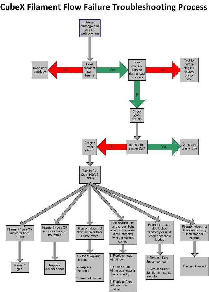
7 Filament Flow Fail Symptoms Test Cause Solution Notes Filament Flow Fail Filament flows OK indicator bars rotate Filament flows OK indicator bars do not rotate Filament does not flow indicator bars do not rotate Run tests in the PJ CONN menu Print Jet too close to bed so unable to print Sticker missing or damaged on drive or idler Faulty sensor board Blocked Print Jet Cartridge jammed Incorrectly inserted filament Reset Z gap Replace sensor board Clean\Replace print jet Replace cartridge Re-load filament Note: Filament flow fail continues on next slide. Tight Z-gap does not allow filament to flow freely Sensor board tells machine whether filament is flowing Filament can catch on lip of print jet 7
8 Filament Flow Fail cont. Symptom Test Cause Solution Filament flow fail cont. Part cooling fans and or part light does not operate when entering Print Jet manual control Filament present dot flashes randomly or is off when filament is loaded Filament does not flow only primary indicator bar rotates Faulty head wiring loom Head connector loose or not seated properly Faulty Print Jet controller module Faulty Print Jet sensor loom Faulty Print Jet filament sensor module Incorrectly inserted filament Replace head wiring loom Check head wiring connector is fitted correctly Replace print jet controller module Replace Print Jet sensor loom Replace Print Jet filament sensor module Re-load filament 8
9
10 Z-gap Loses Position Symptom Test Cause Solution Notes Z-Gap loses its position None Print jet 2 fan fitted Duo: move PJ2 fan to PJ3 position Trio: Remove PJ2 fan Electrical field generated by fan can affect limit switch Old firmware Non Cooltron part cooling fans Update firmware to version 1.06 or newer Change part cooling fans to Cooltron Non-Cooltron fans generated stronger electrical field 10
 Loose Belt Tighten belt as necessary Loose pulley on stepper motor Align pulley screw with flat on motor shaft & re-tighten (Refer to CubeX course 3.")
11 Shift in Print in X or Y axis Symptom Test Cause Solution Print Shift in X or Y axis (this is more common in the X axis) Incorrect stepper motor voltage Adjust stepper motor chip voltage (refer to CubeX course 3.6) Loose Belt Tighten belt as necessary Loose pulley on stepper motor Align pulley screw with flat on motor shaft & re-tighten (Refer to CubeX course 3.8 for assistance) 11
12 Z Axis Will Not Move Up Symptom Test Cause Solution Notes Z will not move up In manual move is there a "Z" in the lower left corner of the screen when carriage in middle of bed Carriage over print pad magnet Move carriage to different position Movement stops in all axis when a limit switch is activated In manual move is there a "Z" in the lower left corner of the screen when carriage to one side Faulty Z limit switch Loose Z-coupler Replace Z limit switch (refer to CubeX course 3.5 for instructions) Align coupler set screw with flat on motor shaft & retighten all 4 set screws 12

13 Touchscreen Flashing Symptom Test Cause Solution Touch screen flashing or parts missing Old firmware Update firmware to version 1.06 or above Old screen (w/o capacitor) Replace screen 13
14 Print Pad Collides with Print Tips Symptom Test Cause Solution Notes Print Pad does not stop rising, collides with print tips. Check for print pad magnet Check Z-limit Switch Magnet missing Weak or bad limit switch Re-attach magnet in correct position Contact Cubify support for warranty replacement of Print Pad See Course 3.5: Replacing/checking limit switches Magnet activates Z- Limit switch Limit switches are both sensitive and fragile. Misalignment or damage will affect performance. 14
15 X,Y Limit Switch Issues Symptom Test Cause Solution Print Jet Carriage does not stop moving at X or Y limits Check adjustment and function of limit switches Weak or bad limit switch See Course 3.5: Replacing/checking limit switches 15
16 Machine Does not Power On Symptom Test Cause Solution Notes Machine Does not Power on Check Power Supply Check Main Board PCB LEDs (2 red) Power supply not connected Machine Electronics Short Circuit Bad Main Board PCB Ensure secure power connections at wall outlet, power brick, and Main Board PCB Contact Cubify support for warranty replacement of Main Board, all Cartridge Bays and Breakout Board Contact Cubify support for warranty replacement of Main Board PCB Short circuits typically occur if repairs are attempted while machine is plugged in. 16
17 Activation Error Symptom Test Cause Solution Notes Activation Error on screen when starting up machine Check Connections from Bay #1 to Main Board PCB Cartridge Bay #1 not connected to Main Board Bad #1 Cartridge Bay Ensure secure connection from Cartridge Bay #1 to Main Board Contact Cubify support for warranty replacement of Cartridge Bay #1 Cartridge Bay #1 Contains serial number information and must be programmed to match main board 17
3D SYSTEMS University CubeX Printer
 3D SYSTEMS University CubeX Printer Lesson Replacing the Z Limit Switch and Checking the X, Y, and Z Limit Switches Revision date: 10/23/13 1 1 2016 年 6 月 14 日 Objectives After completing this lesson you
3D SYSTEMS University CubeX 3D Printer
 3D SYSTEMS University CubeX 3D Printer Lesson Leveling the Print Pad and Print Tips, Setting the Z-Gap Revision date: 10/22/13 1 1 2016 年 6 月 14 日 Objectives After completing this lesson you will: Be able
The following illustration demonstrates what you would see when the print jet nozzles are properly leveled.
 INF Printing Verify the Print Jet Nozzle Level Leveling the print jet nozzles is very important to ensure quality prints especially after replacing a print jet, an extruder assembly or the print pad. The
E3 CNC Router Troubleshooting Guide
 Simple Cost Effective Designs. E3 CNC Router Troubleshooting Guide The purpose of this document is to give those new to CNC routing is a quick reference for the common issues of getting the E3 CNC router
E3 CNC Router Troubleshooting Guide
 Simple Cost Effective Designs. E3 CNC Router Troubleshooting Guide The purpose of this document is to give those new to CNC routing is a quick reference for the common issues of getting the E3 CNC router
X/Y Issues on ASP-645-1
 X/Y Issues on ASP-645-1 Issues seen with X or Y problems: A) Table will not move in X or Y when you are using the Frame Arrow buttons on the control panel. B) On power up the control panel gives Error
Understanding printer messages
 Understanding printer s Printer s that appear on the control-panel display relay the normal status of the printer (such as Processing...) or an error condition (such as CLOSE TOP COVER) that needs attention.
CubePro. INF Printing Best Practices. Introduction. Copyright. Compliance. INF Printing Best Practices
 INF Printing Best Practices CubePro INF Printing Best Practices Introduction Printing with Infinity Rinse-Away (INF) is an exciting endeavor for the 3D printing enthusiast. Now, you can utilize supports
Vector Drive - Troubleshooting Guide
 Haas Technical Documentation Vector Drive - Troubleshooting Guide Scan code to get the latest version of this document Translation Available The Haas Vector drive is the source of power for the spindle
Vector Drive - Troubleshooting Guide
 Haas Technical Documentation Vector Drive - Troubleshooting Guide Scan code to get the latest version of this document Translation Available The Haas Vector drive is the source of power for the spindle
Removal and Installation8
 8 Screw Types 8-4 Top Cover Assembly 8-5 Left Hand Cover 8-6 Right Hand Cover 8-10 Front Panel Assembly 8-14 Left Rear Cover 8-15 Right Rear Cover 8-16 Extension Cover (60" Model only) 8-17 Media Lever
Interpret control-panel messages
 Interpret control-panel messages Control-panel message types Four types of control-panel messages can indicate the status of or problems with the product. Message type Status messages Warning messages
XS/XY Error Messages. Message (Code) A01. No or Low Battery Voltage Error. Wrong Tape Code or BAUD Rate Error A05
 A01. No or Low Battery Voltage Error. Wrong Tape Code or BAUD Rate Error A05") XS/XY Messages Message A01 A05 No or Low Battery Voltage Wrong Tape Code or BAUD Rate If machine has been powered off for a long period time, or a replacement CPU board was installed, the battery maybe
XS/XY Messages Message A01 A05 No or Low Battery Voltage Wrong Tape Code or BAUD Rate If machine has been powered off for a long period time, or a replacement CPU board was installed, the battery maybe
JGAURORA 3D PRINTER MODEL: A-4 USER GUIDE
 JGAURORA 3D PRINTER MODEL: A-4 USER GUIDE 1 Contents 1. Preface...3 1.1 Introduction...3 1.2 Safety matters... 3 1.3 Filament requirements...3 1.4 Environmental requirements...3 2. About A-4... 4 2.1 Basic
Touch Sensor Lighted Cupholder with Power Recline and Power Head Rest. Operating and Trouble Shooting Guide
 Touch Sensor Lighted Cupholder with Power Recline and Power Head Rest Operating and Trouble Shooting Guide Proper User Operation Operating and Set Up Guide If the performance of the power recline function
Dell Latitude C800 Service Manual
 Dell Latitude C800 Service Manual Dell Latitude C800 Service Manual Before You Begin Preparing to Work Inside the Computer Recommended Tools Screw Identification Removing and Replacing Parts System Components
MSR BASIC & MSR NANO USER MANUAL
 MSR BASIC & MSR NANO USER MANUAL An Introduction The MSR BASIC and MSR NANO are both portable magnetic stripe card readers. They utilize 3.7V Lithium Ion batteries and can run for more than 30 days with
Replacing the Encoder Strip
 6-1-11. Replacing the Encoder Strip The following describes the procedure for replacing the Encoder Strip. Refer to the diagram below for identifying the parts and their positions. (The numbers shown in
EPS 06 in rear housing type A1
 Field Installation and / or Replacement of RACO Electronic Position Sensor Board EPS 02 & EPS 06 - Electronic Limit Switches - Analog Output Position Signal - Very Accurate - Easy To Use - Robust - Dependable
Removing and Replacing Parts
 Removing and Replacing Parts Preparing to Work Inside the Computer Recommended Tools Screw Identification System Components Hard Drive Fixed Optical Drive Media Bay Devices Memory Modules Mini PCI Card
DOT MATRIX PRINTER SP6000 SERIES
 DOT MATRIX PRINTER SP6000 SERIES Hardware Manual < Approval: CEL > Trademark acknowledgments SP6000 : Star Micronics Co., Ltd. Notice All rights reserved. Reproduction of any part of this manual in any
Vector 3D printer complete wire list including extruder PWA listing
 Vector 3D printer complete wire list including extruder PWA listing Conventions Pin numbering for connectors It is normal practice in print circuit board (PCB) layout to denote pin 1 of a PCB mounted connector
MH Series Troubleshooting Guide: Rough Draft
 MH Series Troubleshooting Guide: Rough Draft Poor Cutting Lifting Corners: If the corners of the material are getting pulled up then the carriage speed will need to be reduced and the blade depth should
Cutter Option Installation Instructions
 This kit includes the parts and documentation necessary to install the cutter option on the Zebra XiII, XiIII, and XiIIIPlus-Series printers. NOTE: The Cutter Option is not available for the 96XiIII. Adding
CAMERA ASSEMBLY. Removal/Replacement of the Camera Box Assembly APR-CA. Install Camera Assembly. Remove Camera Assembly
 CAMERA ASSEMBLY Removal/Replacement of the Camera Box Assembly APR-CA REQUIRED TOOLS: 9/64 hex key Small flat-tip screwdriver Remove Camera Assembly camera 1. Locate the camera assembly underneath the
Manual for MantraJet 1100 CD/DVD auto-printer
 Manual for MantraJet 1100 CD/DVD auto-printer Rev 1.03 September 7, 2010 Table of contents Specifications...3 Unpacking MantraJet 1100...4 Quick installation reference MantraJet 1100...7 Installation of
Quicksilver 606 TR-606 CPU Upgrade
 Quicksilver 606 TR-606 CPU Upgrade D650C 128 Installation Guide Social Entropy Electronic Music Instruments TABLE OF CONTENTS WARNINGS... 1 OVERVIEW... 2 WHAT'S IN THE BOX... 3 OPENING THE TR-606 CASE...
Inspiron Service Manual. 2-in-1. Computer Model: Inspiron Regulatory Model: P69G Regulatory Type: P69G001
 Inspiron 13 5000 2-in-1 Service Manual Computer Model: Inspiron 13-5378 Regulatory Model: P69G Regulatory Type: P69G001 Notes, cautions, and warnings NOTE: A NOTE indicates important information that helps
Panowin F1. User Manual
 Panowin F1 User Manual 1 PANOWIN TECHNOLOGIES CO.,LTD. WARNING power outlet. CAUTION: In case of emergency unplug the Panowin F1 from the WARNING: Carefully monitor the Panowin F1 during operation. Do
Agenda. Breaking the Ice Physical Setup Walkthrough of REPETREL First Print
 T1 Training Session Agenda Breaking the Ice Physical Setup Walkthrough of REPETREL First Print Breaking the Ice SYSTEM 30M ENGINE Breaking the Ice Protected build environment Slightly larger build area
SERIES 7 TABLES PRE-DECEMBER Troubleshooting Guide. IMPORTANT NOTE: This guide applies to models shipped prior to December 2015 only.
 Troubleshooting Guide Control Box (PRE-DECEMBER 2015) Low-Voltage Cable Cable Manager Controller Lifting Column Stretcher Foot Power Cable SERIES 7 TABLES PRE-DECEMBER 2015 HOW THEY WORK Each Lifting Column
Model: 3-Axis High Quality Self-Assembled 3D Printer Kit. Panowin F1
 ESTIMATE No.: Client: Telephone: E-mail: Address: City, State: Contact: Cell-Phone: Fax: Zip Code: Country: Panowin Technologies Co., Ltd. Model: 3-Axis High Quality Self-Assembled 3D Printer Kit Panowin
Documentation version Prusa i3 Rework USER GUIDE REV 1.5. Document Version 1.1.8
 Documentation version 1.1.8 Prusa i3 Rework USER GUIDE REV 1.5 2 INTRODUCTION Target : Prupose a visual guide of the differents steps to build and use a Prusa i3 Rework. Authors of this document : emotion
Cura (Documentation for version )
") Cura (Documentation for version 15.04.06) Getting Started Installation To start the installation of Cura, download it first. After downloading, open the installer and run the installation wizard to complete
Cura (Documentation for version 15.04.06) Getting Started Installation To start the installation of Cura, download it first. After downloading, open the installer and run the installation wizard to complete
This equipment conforms with International Electric Committee (IEC) and meets the requirements of the applicable EC directives.
 and meets the requirements of the applicable EC directives.") Print Jet and Extruder Replacement Guide CubePro Print Jet and Extruder Replacement Guide Introduction Copyright 2014 by 3D Systems, Inc. All rights reserved. This document is subject to change without
Print Jet and Extruder Replacement Guide CubePro Print Jet and Extruder Replacement Guide Introduction Copyright 2014 by 3D Systems, Inc. All rights reserved. This document is subject to change without
Troubleshooting with the control panel
 Troubleshooting with the control panel The tables in this section explain common messages that might appear on the control-panel display. Within each table, the messages and their meanings are listed in
CHAPTER 3B: ELECTRONIC POWER STEERING
 Electronic Power Steering CHAPTER 3B: ELECTRONIC POWER STEERING NOTE: The basic steering system, such as the tie rod ends, drag links axles, etc., is covered in Chapter 3A: Steering. In 2012, Cub Cadet
3d Printing with the Prusa I3 Operation & Printing via a USB Cable
 3d Printing with the Prusa I3 Operation & Printing via a USB Cable Instructions for: Prusa I3 Printer Set-up Slic3r Software Use Pronterface Software Use Prusa I3 - Parts Identification Prusa I3 Printer
Vector Drive - Troubleshooting Guide
 Haas Technical Documentation Vector Drive - Troubleshooting Guide Scan code to get the latest version of this document Translation Available The Haas Vector drive is the source of power for the spindle
Replacing the PanelMate Power Pro 1785 Series, PanelMate epro 7585x-8 and 7685x-8 Series Backlight Assembly
 Replacing the PanelMate Power Pro 1785 Series, PanelMate epro 7585x-8 and 7685x-8 Series Assembly Introduction The Replacement Kit provides a replacement backlight for the PanelMate Power Pro 1785 Series,
English. Quick Guide
 English Quick Guide Specification Product Overview Button and Indicator light Unpacking Accessory Checklist Important Safety Notes Extruder module installation Accessory installation XYZware operation
ideamaker Manual
 ideamaker Manual Using ideamaker... 2 Basic information... 2 What is ideamaker?... 2 Where to download ideamaker?... 2 Install ideamaker... 3 Let s Print!... 6 How to use ideamaker?... 23 Interface...
Software Manual. Revision 1.3
 Software Manual Revision 1.3 Copyright 2015 by Kudo3D. This material may be distributed only subject to the terms and conditions set forth in the Creative Commons Attribution-NonCommercial-NoDerivatives
SP-7 AHRS. Firmware upgrade instructions. Installation and calibration
 SP-7 AHRS Firmware upgrade instructions Installation and calibration General This document describes the firmware upgrade procedure and new functionality of the SP-7 Firmware release. The firmware upgrade
Installation, Operation and Maintenance Manual
 Document 481200 VGD-100 Vari-Green Drive Installation, Operation and Maintenance Manual Please read and save these instructions for future reference. Read carefully before attempting to assemble, install,
da Vinci Jr.1.0 April 2016 da Vinci Junior 1.0w 3D Printer da Vinci Jr.1.0w Quick Guide HD23F1JW0N1
 da Vinci Junior 1.0w 3D Printer w Quick Guide P 1 Product Overview A: Filament movement area B: Feed module C: Detector D: Extruder E: Filament F: Print bed G G: SD card port (Storage format: FAT32) H:
MEGATRONICS V3.0 QUICK START GUIDE
 MEGATRONICS V3.0 QUICK START GUIDE Thank you for purchasing the Megatronics v3.0! This small guide will answer the basic questions on how to connect the board to your 3D printer. For more information visit
TOSHIBA Potable Printer B-EP4DL SERIES. Maintenance Manual. Document No. EO Original Sep., 2008 (Revised ) PRINTED IN JAPAN
 PRINTED IN JAPAN") TOSHIBA Potable Printer B-EP4DL SERIES Maintenance Manual Original Sep., 2008 (Revised ) Document No. EO18-33023 PRINTED IN JAPAN WARNING! Follow all manual instructions. Failure to do so could create
TOSHIBA Potable Printer B-EP4DL SERIES Maintenance Manual Original Sep., 2008 (Revised ) Document No. EO18-33023 PRINTED IN JAPAN WARNING! Follow all manual instructions. Failure to do so could create
CF3000 Dealer Diagnostic Tool Instruction Manual
 CF3000 Dealer Diagnostic Tool Instruction Manual Table of Contents: About the CF3000......3 Important Precautions......4 Components....5 Charging the CF3000......7 Licensing the CF3000.......8 Updating
Calibration and Maintenance
 Epson DX5 X 1 Printhead Calibration and Maintenance 31 st Jan., 2013 Version V3.0 1 Contents Chapter 1: Computer Requirement...3 Chapter 2:Installation...4 Chapter 3:Characteristic...5 Chapter 4:Board
MantraJet 1100 CD/DVD autoprinter Operator s manual
 MantraJet 1100 CD/DVD autoprinter Operator s manual Rev 1.00 May 7, 2008 Table of contents 1. Specifications.. Page 2 2. Unpacking you MantraJet 1100 Page 3 3. Using your autoprinter for the first time.
CubePro. Main PCB Replacement Guide. Prosumer 3D Printer. Original Instructions
 CubePro Prosumer 3D Printer Main PCB Replacement Guide Original Instructions 1 INTRODUCTION COPYRIGHT 2014 by All rights reserved. This document is subject to change without notice. This document is copyrighted
Dell Latitude C800 SERVICE MANUAL. support.dell.com
 Dell Latitude C800 SERVICE MANUAL www.dell.com support.dell.com Dell Latitude C800 SERVICE MANUAL www.dell.com support.dell.com Notes, Notices, and Cautions NOTE: A NOTE indicates important information
Dell Inspiron XPS and Inspiron 9100 Service Manual
 Dell Inspiron XPS and Inspiron 9100 Service Manual Dell Inspiron XPS and Inspiron 9100 Service Manual Before You Begin Memory Module, Mini PCI Card, and Devices System Components Subwoofer Bluetooth Card
Replacing the TFM coupler
 Repair manual Replacing the TFM coupler Instructions The TFM coupler is a key component of the hot end. It allows filament to flow smoothly through it from the Bowden tube and towards the nozzle. The coupler
RazorGage Inkjet Printer Changing the Character Aspect Ratio & Spacing
 RazorGage Inkjet Printer Changing the Character Aspect Ratio & Spacing RazorOptimal Software From the Main Screen Press Diagnostics From the Diagnostics Screen press Evolution Inkjet Autolist Software
Most Common Error Codes Guide. Error Codes & Definitions
 Most Common Error Codes Guide Embedded Touch Screens This guide contains troubleshooting for the most common error codes that may occur on an embedded touch screen. Error Codes & Definitions Error Code
Makeblock Constructor I 3D Printer Kit. 2. 3D Printer Wiring Guide
 2. 3D Printer Wiring Guide 1 Content 2.1. Parts Required... 3 2.2 preparation... 7 2.2.1 Add heat sinks on the top of stepper motor driver chip... 7 2.2.2 Plug the jumper cap into corresponding position...
DIY PRINTER INSTALLATION AND OPERATION INSTRUCTION
 CTC DIY I3 PRINTER INSTALLATION AND OPERATION INSTRUCTIONS Thank you for buying and using DIY 3D printer produced by CTC Please read the installation and operation instruction carefully before use Company
XPS 15 2-in-1. Service Manual. Computer Model: XPS Regulatory Model: P73F Regulatory Type: P73F001
 XPS 15 2-in-1 Service Manual Computer Model: XPS 15-9575 Regulatory Model: P73F Regulatory Type: P73F001 Notes, cautions, and warnings NOTE: A NOTE indicates important information that helps you make better
Troubleshooting CHAPTER
 CHAPTER 1 1 1 1 0 1 1 0 1 1 0 1 1 0 1 1 0 1 1 0 1 1 0 1 1 1 0 1 6 0 1 1 0 1 1 0 1 0 1 10 1 0 1 1 0 1 0 1 1 0 1 0 1 1 0 1 10 Troubleshooting NOTICE: Information in this manual may change without notice.
OLOGY HEIGHT-ADJUSTABLE DESKS. Troubleshooting Guide
 Troubleshooting Guide Power Cable Cantilevers Control Box Low-Voltage Cable Controller Lifting Column Foot Understructure OLOGY HEIGHT-ADJUSTABLE DESKS HOW THEY WORK Each Lifting Column contains an individual
Control-panel messages
 Control-panel messages Control panel message Description Recommended action 10.32.YY UNAUTHORIZED SUPPLY Unauthorized supply in use A new, non-hp supply has been installed. This message appears until you
Vision Fitness TF20-TF40-T40 Frame with Classic / Elegant / Touch Console Service Manual
 Vision Fitness TF20-TF40-T40 Frame with Classic / Elegant / Touch Console Service Manual 1 TABLE OF CONTENTS CHAPTER 1: SERIAL NUMBER LOCATION 1.1 Serial Number Location - TF20 Frame.....3 1.2 Serial Number
The GENIE Light Kit is ideal for introducing simple lighting projects, such as an electronic die, a wearable badge or a night-time warning system.
 Introduction 1 Welcome to the GENIE microcontroller system! The GENIE Light Kit is ideal for introducing simple lighting projects, such as an electronic die, a wearable badge or a night-time warning system.
SERVICE MANUAL. Power Plant Premier APPLICABLE PRODUCTS. Serial numbers PPP-7J and earlier. Document # DSM-A Released 01/08
 SERVICE MANUAL Power Plant Premier APPLICABLE PRODUCTS Serial numbers PPP-7J and earlier Document # 11-037-01-1-DSM-A Released 01/08 BASIC DISASSEMBLY PROCEDURE 1) Place the unit upside down on a well
Printing Your First Page. Attaching the Paper Support. Plugging in the Printer. Checking the Printer
 Printing Your First Page Attaching the Paper Support Checking the Printer Plugging in the Printer Installing the Ink Cartridges Installing the Printer Software Connecting the Printer 4011307 XXX-00 Attaching
Control Box Setup - PRSalpha
 888-680-4466 ShopBotTools.com Control Box Setup - PRSalpha Copyright 2016 ShopBot Tools, Inc. page 1 Copyright 2016 ShopBot Tools, Inc. page 2 Parts List: Hooking Up a PRSalpha Gantry Tool Powering the
OLOGY HEIGHT-ADJUSTABLE DESKS. Troubleshooting Guide
 Troubleshooting Guide Power Cable Cantilevers Control Box Low-Voltage Cable Controller Lifting Column Foot Understructure OLOGY HEIGHT-ADJUSTABLE DESKS HOW THEY WORK Each Lifting Column contains an individual
Alienware Area-51 R5 Service Manual
 Alienware Area-51 R5 Service Manual Computer Model: Alienware Area-51 R5 Regulatory Model: D03X Regulatory Type: D03X002 Notes, cautions, and warnings NOTE: A NOTE indicates important information that
TROUBLESHOOTING CHAPTER
 CHAPTER TROUBLESHOOTING CAUTION: Turn AC power off before attempting any of the following procedures, unless otherwise specified. Failure to do so may damage equipment, cause personal injury, or void warranty.
M7 SERIES Thermal Printer Service Manual 4. PART LIST. 4.1 Main Printer Assemblies
 4. PART LIST 4.1 Main Printer Assemblies 31 No. Part No. Description Remark Spare Requirement 1 120732 Electronics cover 1 pc 2 N/A Mainframe 1 pc 3 120733 Cover, front 1 pc 4 120734 Top right side cover
Paramount Electronics Replacement Instructions
 Paramount Electronics Replacement Instructions Revision 1.7, October 2017 2017 Software Bisque, Inc. All rights reserved. Contents Replacing Paramount Electronics... 3 Step 1: Save Existing Control System
Written By: Jakub Dolezal
 5. Preflight check Written By: Jakub Dolezal 2018 manual.prusa3d.com/ Page 1 of 17 Step 1 P.I.N.D.A. adjustment (part 1) Ensure the printer is turned off and not plugged in. Note your extruder is slightly
Parts List: Assembly Instructions:
 My Ride SERVICE MANUAl MyRide ASSEMBLY GUIDE 1.1 ASSEMBLY INSTRUCTIONS ASSEMBLING THE MYRIDE Parts List: Heavy Plate Stabilizer Fin - Right Stabilizer Fin - Left Stabilizer Fin - Large Middle Power Cord
7 Troubleshooting. Chapter contents
 7 Troubleshooting Chapter contents Introduction.......................................... 205 Troubleshooting process................................ 206 Pre-troubleshooting checklist.........................
Chapter 2: Disassembly
 P370EM / P370EM3 Chapter 2: Overview This chapter provides step-by-step instructions for disassembling the P370EM / P370EM3 series notebook s parts and subsystems. When it comes to reassembly, reverse
Instructions & Software Install Version 6.30a (Feb 2018) Copyright 2018 DealerTool.co.uk
 Copyright 2018 DealerTool.co.uk") DealerTool Instructions & Software Install Version 6.30a (Feb 2018) Copyright 2018 DealerTool.co.uk If you have any problems please email support@dealertool.co.uk Emails will always be responded to within
DealerTool Instructions & Software Install Version 6.30a (Feb 2018) Copyright 2018 DealerTool.co.uk If you have any problems please email support@dealertool.co.uk Emails will always be responded to within
Mistral 260. User manual. (SHA One) Forced Air Convection Oven. Version 2.11
 Forced Air Convection Oven. Version 2.11") Mistral 260 (SHA One) Forced Air Convection Oven User manual Version 2.11 Inhoud 1. Preface... 2 2. Setting up... 3 WARNINGS:... 3 3. Working with the TFT touch screen... 5 3.1 Starting the program...
Mistral 260 (SHA One) Forced Air Convection Oven User manual Version 2.11 Inhoud 1. Preface... 2 2. Setting up... 3 WARNINGS:... 3 3. Working with the TFT touch screen... 5 3.1 Starting the program...
INTELLI-HOOD TROUBLESHOOTING GUIDE
 INTELLI-HOOD TROUBLESHOOTING GUIDE Melink Corporation (513) 965-7300 www.melinkcorp.com Last Updated 7/22/2015 Table of Contents Page I. About this Document 2 II. Related Documents 2 III. Glossary of Abbreviations
Evolve 3 & 5 Service Manual
 Evolve 3 & 5 Service Manual 1 Product Browse 2 Contents CHAPTER 1: SERIAL NUMBER LOCATION... 5 CHAPTER 2: CONSOLE INSTRUCTIONS 2.1 Console Overview... 6 2.1.1 Evolve 3 Console Overview... 6 2.1.2 Evolve
HQ Pro-Stitcher Hardware Upgrade Installation Instructions 01/15/13
 Getting Started Monitor Styles HQ Pro-Stitcher Hardware Upgrade Installation Instructions 01/15/13 1. Identify the monitor style on your HQ Pro-Stitcher by comparing to the photos at the right. 2. Find
HP Pavilion dv7-6c90us Cooling fan Replacement
 HP Pavilion dv7-6c90us Cooling fan Replacement This guide will walk you through the process of replacing the cooling fan in an HP Pavilion dv7 laptop. Written By: Angelina Clayton ifixit CC BY-NC-SA www.ifixit.com
[Note: Power adapter is not included in the kits. Users need to prepare a 9 12 V ( >300mA capacity ) DC power supply]
![[Note: Power adapter is not included in the kits. Users need to prepare a 9 12 V ( >300mA capacity ) DC power supply]](/thumbs/76/74094055.jpg "[Note: Power adapter is not included in the kits. Users need to prepare a 9 12 V ( >300mA capacity ) DC power supply]") 062 LCD Oscilloscope Assembly Notes Applicable Models: 06203KP, 06204KP DN062-18v02 Important Notes 1. Some components shown in the schematic and PCB layout are for options or adjustments. They do not
062 LCD Oscilloscope Assembly Notes Applicable Models: 06203KP, 06204KP DN062-18v02 Important Notes 1. Some components shown in the schematic and PCB layout are for options or adjustments. They do not
Dreamer Series User Manual
 Dreamer Series User Manual Welcome to the world of the Dreamer. To ensure that you have the best possible user experience, it s important that you follow this user manual. Let s get started! In Parts I
Phase Loss Protection Upgrade. Phase Loss Protection Upgrade. In this bulletin:
 Phase Loss Protection Upgrade In this bulletin: Introduction... 2 Purpose... 2 General... 2 Applicability... 2 HD3070 Phase Loss Protection Upgrade Kit Parts... 2 Preparation... 4 Install the Phase Loss
TD-700 FLUOROMETER SERVICE MANUAL
 TD-700 FLUOROMETER SERVICE MANUAL July 1996 CONTENTS Page Section 1 INTRODUCTION 2 Section 2 PRELIMINARY CHECKS 3 Section 3 TROUBLESHOOTING GUIDE 5 A. Lamp (Fluorescent) 5 B. Lamp Heater 7 C. Fan 8 D.
Service Bulletin. Music Link (For ipod) General Information and Symptom Troubleshooting
 General Information and Symptom Troubleshooting") Applies To: ALL with accessory Music Link installed Service Bulletin 07-010 February 16, 2007 Music Link (For ipod) General Information and Symptom Troubleshooting BACKGROUND Acura Music Link is an Acura
Applies To: ALL with accessory Music Link installed Service Bulletin 07-010 February 16, 2007 Music Link (For ipod) General Information and Symptom Troubleshooting BACKGROUND Acura Music Link is an Acura
10 Rules You Should Know To Keep Your Dot Matrix Printer Operational
 1 2 from the desk of Ken Feinstein Dear Reader, So many times we repair dot matrix printers that we feel a service call could have been prevented. We ve compiled a list of the most common preventative
Unplug the power of your current controller.
 Contents -1- Preparation Test the functionality of your irrigation system with your current controller first. If it does not work, please make sure it is repaired before installing the Sprite. Note: If
3.5AE & 7.5AE Service Manual
 3.5AE & 7.5AE Service Manual 1 2 3 Contents CHAPTER 1: SERIAL NUMBER LOCATION... 5 CHAPTER 2: CONSOLE INSTRUCTIONS 2.1 Console Overview... 6 2.2 Display Window Indication... 8 2.3 Getting Started & Program
User's Manual. For ST-6560V3. Version All Rights Reserved
 User's Manual For ST-6560V3 Version 2.0 2016.08.25 All Rights Reserved 1. Key Features Toshiba TB6560AHQ chip - High power, maximum current 3.5A Resolution 1, 1/2, 1/8, 1/16 micro stepping output Working
Tech Tips. BeeBots. WeDo
 Tech Tips Teachers, especially classroom teachers who are implementing a robotics unit in their classroom, may not have much troubleshooting experience and may not have ready access to tech support. As
ATTENTION: OBSERVE PRECAUTIONS FOR HANDLING ESD-SENSITIVE DEVICES
 Hard Drive Removal IMPORTANT NOTE: If you are replacing a PATA hard drive with a SATA hard drive, please see PATA to SATA Hard Drive Conversion. Hard Drive Identification: To determine whether your hard
Portabee GO. Mobile 3D Printer. Portabee 3D. Romscraj. Software & Support. Manufacturing & Engineering.
 Portabee GO Mobile 3D Printer Portabee 3D Software & Support http://portabee3d.com support@portabee3d.com Romscraj Manufacturing & Engineering http://romscraj.com contact@romscraj.com A. Software Package
Instructions for SVC-KIT-0020
 Kaleidescape, Inc. July 22, 2010 Instructions for SVC-KIT-0020 Title Time to complete 1U Server Power Supply Replacement 1 hour Procedure to complete Locate Parts and Tools Service Kit Parts Power supply
Lightning Stitch Assembly
 ABM International, Inc. 1 1.0: Parts List Lightning stitch motor and drive assembly (Qty. 1) Lightning stitch piggy backed controller board assembly (Qty. 1) Touchscreen (Qty. 1) 2 9-pin Serial cable (Qty.
Service Calibrations 5
 5 Service Calibrations 5-3 ing the Service Calibrations Menu 5-4 1. Scan-Axis Calibration 5-7 2. Service Station Calibration 5-11 3. Accuracy Calibration 5-14 Carriage Height Calibration 5-18 Calibration
DNS User Manual. Version Dec DataON Storage, storage division of Area Data Systems.
 DNS-2670 User Manual Version Dec. 2015 DataON Storage, storage division of Area Data Systems. Contents 1 Introduction... 1 1.1 System Overview... 3 1.1.1 System Top View...3 1.1.2 Front View...4 1.1.3
 This tutorial was written by Team Xecuter. If you use anything from this tutorial please give credits and also a direct link to this page. Also if we have made any mistakes or left anything out please