Week 11 Programmable Interrupt Controller
|
|
|
- Amy Watts
- 6 years ago
- Views:
Transcription
1 Week 11 Programmable Interrupt Controller
2 8259 Programmable Interrupt Controller The 8259 programmable interrupt controller (PIC) adds eight vectored priority encoded interrupts to the microprocessor. This controller can be expanded to accept up to 64 interrupt requests. This requires a master 8259 and eight 8259 slaves. Vector an Interrupt request anywhere in the memory map. Resolve eight levels of interrupt priorities in a variety of modes, such as fully nested mode, automatic rotation mode, and specific rotation mode. Mask each of the interrupt request individually Read the status of the pending interrupts, in-service interrupts and masked interrupts. 2

3 Block Diagram 3
4 82C59A Programmable Interrupt Controller Block diagram of 82C59A includes 8 blocks 8259 is treated by the host processor as a peripheral device is configured by the host pocessor to select functions. Data bus buffer and read-write logic: are used to configure the internal registers of the chip. A0 address selects different command words within the
5 82C59A Programmable Interrupt Controller Control Logic INT and INTA ared used as the handshaking interface. INT output connects to the INTR pin of the master and is connected to a master IR pin on a slave. INTA is sent as a reply. In a system with master and slaves, only the master INTA signal is connected. Interrupt Registers and Priority Resolver: Interrupt inputs IR 0 to IR 7 can be configured as either level-sensitive or edge-triggered inputs. Edge-triggered inputs become active on 0 to 1 transitions. 1. Interrupt request register (IRR): is used to indicate all interrupt levels requesting service. 2. In service register (ISR): is used to store all interrupt levels which are currently being serviced. 3. Interrupt mask register (IMR): is used to enable or mask out the individual interrupt inputs through bits M0 to M7. 0= enable, 1= masked out. 4. Priority resolver: This block determines the priorities of the bits set in the IRR. The highest priority is selected and strobed into the corresponding bit of the ISR during the INTA sequence. The priority resolver examines these 3 registers and determines whether INT should be sent to the MPU 5
6 82C59A Programmable Interrupt Controller Cascade-buffer comparator: Sends the address of the selected chip to the slaves in the master mode and decodes the status indicated by the master to find own address to respond. Cascade interface CAS 0 -CAS 2 and SP /EN : Cascade interface CAS 0 -CAS 2 carry the address of the slave to be serviced. SP /EN :=1 selects the chip as the master in cascade mode :=0 selects the chip as the slave in cascade mode :in single mode it becomes the enable output for the data transiver 6
 The 82C59A evaluates those requests in the priority resolver with the IMR and ISR, resolves the priority and sends an interrupt (INT) to the CPU, if appropriate.")
7 Interrupt Sequence 1) One or more of the INTERRUPT REQUEST lines (IR0 - IR7) are raised high, setting the corresponding IRR bit(s). 2) The 82C59A evaluates those requests in the priority resolver with the IMR and ISR, resolves the priority and sends an interrupt (INT) to the CPU, if appropriate. 3) The CPU acknowledges the lnt and responds with first INTA pulse. 4) During this INTA pulse, the appropriate ISR bit is set and the corresponding bit in the IRR is reset (to remove request). The 82C59A does not drive the data bus during the first INTA pulse. 5) The 80C86/88/286 CPU will initiate a second INTA pulse. The 82C59A outputs the 8-bit pointer onto the data bus to be read by the CPU. 6) This completes the interrupt cycle. In the Automatic End of Interrupt (AEOI) mode, the ISR bit is reset at the end of the second INTA pulse. Otherwise, the ISR bit remains set until an appropriate End of Interrupt (EOI) command is issued at the end of the interrupt subroutine. 7


8 Content of the Interrupt Vector Byte 8
9 Two controllers wired in cascade On the PC, the controller is operated in the fully nested mode Lowest numbered IRQ input has highest priority Interrupts of a lower priority will not be acknowledged until the higher priority interrupts have been serviced 9
10 Fully Nested Mode It prioritizes the IR inputs such that IR0 has highest priority and IR7 has lowest priority This priority structure extends to interrupts currently in service as well as simultaneous interrupt requests For example, if an interrupt on IR3 is being serviced (IS3 = 1) and a request occurs on IR2, the controller will issue an interrupt request because IR2 has higher priority. But if an IR4 is received (or any interrupt higher than IR2), the controller will not issue the request Note however that the IR2 request will not be acknowledged unless the processor has set IF within the IR3 service routine In all operating modes, the IS bit corresponding to the active routine must be reset to allow other lower priority interrupts to be acknowledged This can be done by outputting manually a special nonspecific EOI instruction to the controller just before IRET Alternatively, the controller can be programmed to perform this nonspecific EOI automatically when the second INTA pulse occurs 10
11 Interrupt Process Fully Nested Mode 11
12 End of Interrupt The In Service (IS) bit can be reset automatically following the trailing edge of the last in sequence INTA pulse (when AEOI bit in ICW4 is 1) or by a command word that must be issued to the 8259 before returning from a service routine (EOI command). An EOI command must be issued twice in the Cascade mode, once for the master and once for the corresponding slave. There are two forms of (non-automatic) EOI command: Specific: When there is a mode which may disturb the fully nested structure, the 8259 may not determine the last level acknowledged. In this case a specific EOI must be issued, which includes the IS level to be reset. (OCW2) Non Specific: When a Non Specific EOI issued the 8259 will automatically reset the highest IS bit of those that are set, since in the fully nested mode the highest level was necessarily the last level acknowledged and serviced. (preserve the nested structure) A non Specific EOI can be also issued at OCW2. 12
13 Initialization Sequence Two types of command words are provided to program the 8259: 1) The initialization command words (ICW) 2) The operational command words (OCW) Writing ICW1, clears ISR and IMR Also Special Masked mode SMM in OCW3, IRR in OCW3 and EOI in OCW2 are cleared to logic 0. Fully Nested Mode is entered. ICW3 and ICW4 are optional It is not possible to modify just one ICW. Whole ICW sequence must be repeated 13
14 ICW1 What value should be written to ICW1 in order to configure the 8259 so that ICW4 needed, the system is going to use multiple 8259s and its inputs are level sensitive? b = 19h 14
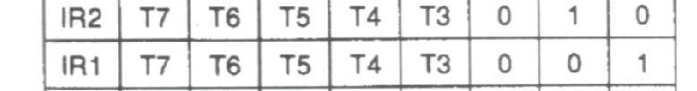
15 ICW2 What should be programmed into register ICW2 if type number output on the bus is to range from F0h to F7h b = F0h Suppose IR6 is set to generate the value of 6E. Generate the addresses for the other interrupts. IR7 = 6F IR3 = 6B IR6 = 6E IR2 = 6A IR5 = 6D IR1 = 69 IR4 = 6C IR0 = 68 15
16 Master Slave Configuration 16
17 Master Slave Configuration When slave signals the master that an interrupt is active the master determines whether or not its priority is higher than that of any already active interrupt. If the new interrupt is of higher priority the master controller switches INTR to logic 1 17
18 Master Slave Configuration This signals MPU that external device needs to be serviced. If IF is set. As the first INTA is sent out the master is signaled to output the 3 bit cascade code of the slave device whose whose interrupt request is being acknowledged on the CAS bus. All slaves read this code and compare internally The slave corresponding to the code is signaled to output the type number of its highest priority active interrupt on the data bus during the second INTA cycle. 18
19 ICW3 Q) Suppose we have two slaves connected to a master using IR0 and IR1. A) The master is programmed with an ICW3 of 03h, one slave is programmed with an ICW3 of 00h and the other with an ICW3 of 01h. 19
20 Example Master-Slave aany requests on interrupt lines INT7 through INT14 will cause IR6 to be activated on the MASTER. athe MASTER will then examine the bit 6 in its ICW3 to see if it is set. aif so it will output the cascade number of the SLAVE on CAS0 through CAS2. athese cascade bits are received by the SLAVE device which examines its ICW3 to see if there is a match.. athe programmer must have programmed 110 into the SLAVE S ICW3. If there is a match between the cascade number and ICW3, the SLAVE device will output the appropriate vector number during the second INTA pulse. 20
21 ICW4 AEOI mode requires no commands. During the second INTA the ISR bit is reset. The major drawback with this mode is that the ISR doesn t have info on which IR is served. Thus any IR with any priority can now Interrupt service routine. BUF when 1 selects buffer mode. The SP/EN pin becomes an output for the data buffers. When 0, the SP/EN pin becomes the input for the (MASTER/SLAVE) functionality M/S is used to set the function of the 8259 when operated in buffered mode. If M/S is set the 8259 will function as the MASTER. If cleared will function as SLAVE. 21
22 Masks and Other Mode selection Interrupt Masks Each Interrupt request can be masked individually by the IMR programmed through OCW1. Each bit in the IMR masks one interrupt channel if it is set (1). Bit 0 masks IR0, Bit 1 masks IR1 and so forth, Masking an IR channel does not affect the other channels operation. 22
23 Special Fully Nested Mode Used in the case of a large system where cascading is used, and the priority has to be conserved within each slave. This mode is similar to the normal nested mode with the following: When an interrupt request from a certain slave is in service this slave is not locked out from the master s priority logic and further interrupt requests from higher priority IR s within the slave will be recognized by the master and will initiate interrupts to the processor. When exiting the ISR the software has to check whether the interrupt is the only interrupt that is serviced from the SLAVE. This is done by sending an EOI command and check the In service register in the SLAVE. If it is the only one, a non specific EOI has to be sent to the MASTER, if it is not empty no action performed. 23

24 Automatic Rotation Several interrupt sources all of equal priority When the EOI is issued the IS bit is reset and then assigned the lowest priority The priority of of other inputs rotate accordingly 24
25 Automatic Rotation interrupt requests arrive on IR4 and IR6 EOI command always resets the highest ISR bit (bit of highest priority) Use automatic rotating mode to clear the IS bit as soon as it is acknowledged 25
26 Specific Rotation The programmer can change priorities by programming the bottom priority and thus fixing all other priorities (for ex: if IR5 is programmed as the bottom priority device, then IR6 will have the highest one) The set priority command is issued in OCW2 where R=1, SL=1, L0-L2 is the binary priority level code of the bottom priority device) 26
27 OCW1 - OCW2 OCW1 is used to access the contents of the IMR. A READ operation can be performed to the IMR to determine the present setting of the mask. Write operations can be performed to mask or unmask certain bits. Controller will not confuse OCW2 with ICW1 since D4 = 1 27
28 Example ISR PROC FAR MOV AL, b OUT 20h, AL IRET ISR ENDP What should be OCW1 if interrupt inputs IR0 through IR3 are to be masked and IR4 through IR7 are to be unmasked? D3D2D1D0 = 1111 D7..D4 = = 0F What should be OCW2; if priority scheme rotate on non specific EOI issued (since it doesn t have to be specific on certain bit 28
29 OCW3 Permits reading of the contents of the ISR or IRR registers through software 29
30 Example Normally when an IR is acknowledged and EOI is not issued, lower priority interrupts will be inhibited. So the SPECIAL MASK MODE, when a mask bit is set in OCW1, it inhibits further interrupts at that level and end enables from all other levels, that are not masked. MOV AL, b ; mask IRQ4 OUT 21h, AL ; OCW1 (IMR) MOV AL, b ; special mask mode OUT 20h, AL ; OCW3 ; by masking itself and selecting the special mask mode interrupts on IRQ5 thru IRQ7 will now be accepted by the controller as well as IRQ0 thru IRQ3 30
31 IR7 Controller does not remember interrupt requests that are not acknowledged If an interrupt is requested but no IR bit is found during INTA that is IR is removed before acknowledged, then controller will default to an IR7 If the IR7 input is used for a legitimate device, the service routine should read the IS register and test to be sure that bit 7 is high ISR7 PROC FAR MOV OUT IN TEST JZ FALSE: IRET ISR7 AL, b 20h, AL AL, 20h AL, 80h ; IS7 set FALSE ; process interrupt here ENDP 31
32 Example Analyze the circuit and write an appropriate main program and a service routine that counts as a decimal number the positive edges of the clock signal applied to IR0 Use type number 72 32
33 Example A0 not used Two I/O addresses are FF00h and FF02h FF00h: ICW1, FF02h: ICW2, ICW3, ICW4, OCW1 ICW1 = b = 13h type number 72 will be used ICW2 = b = 48h ICW3 not needed nonbuffered and auto EOI ICW4 = 03h mask all other interrupts but IR0 OCW1 = b = FEh 33
34 Main program and ISR CLI START: MOV AX, 0 MOV ES, AX MOV AX, 100h MOV DS, AX MOV AX, 0FF0h; stack MOV SS, AX MOV SP, 100h ; interrupt install MOV AX, OFFSET SRV72 MOV [ES:120h], AX MOV AX, SEG SRV72 MOV [ES:122h]. AX 34
35 Example contd ; initialization MOV DX, 0FF00h MOV AL, 13h OUT DX, AL MOV DX, 0FF02h MOV AL, 48h OUT DX, AL MOV AL, 03h OUT DX, AL MOV AL, 0FEh OUT DX, AL STI ; wait for interrupt HERE: JMP HERE ; service routine SRV72: PUSH AX MOV AL, [COUNT] INC AL DAA MOV [COUNT], AL POP AX IRET 35
Interrupts. by Rahul Patel, Assistant Professor, EC Dept., Sankalchand Patel College of Engg.,Visnagar
 Chapter 12 Interrupts by Rahul Patel, Assistant Professor, EC Dept., Sankalchand Patel College of Engg.,Visnagar Microprocessor & Interfacing (140701) Rahul Patel 1 Points to be Discussed 8085 Interrupts
Lecture-51 INTEL 8259A Programmable Interrupt Controller
 Lecture-51 INTEL 8259A Programmable Interrupt Controller The 8259A is a programmable interrupt controller designed to work with Intel microprocessor 8080 A, 8085, 8086, 8088. The 8259 A interrupt controller
8086 Interrupts and Interrupt Responses:
 UNIT-III PART -A INTERRUPTS AND PROGRAMMABLE INTERRUPT CONTROLLERS Contents at a glance: 8086 Interrupts and Interrupt Responses Introduction to DOS and BIOS interrupts 8259A Priority Interrupt Controller
sequence is not needed. (ROM space). Another application is to use the poll mode to expand the number of priority levels to more than 64.
. Another application is to use the poll mode to expand the number of priority levels to more than 64.") Lecture-55 Poll Command: In this mode the INT output is not used for the microprocessor internal interrupt enable F/F is reset, disabling its interrupt input, service to device is achieved by software
Lecture-55 Poll Command: In this mode the INT output is not used for the microprocessor internal interrupt enable F/F is reset, disabling its interrupt input, service to device is achieved by software
Lecture-61 Initialization Control Word 2 (ICW2):
:") Lecture-61 Initialization Control Word 2 (ICW2): After issuing ICW1 on even address, the PIC is ready to accept initialization Control Word 2. It is issued to an address having A 0 =1, i.e., on odd address.
Lecture-61 Initialization Control Word 2 (ICW2): After issuing ICW1 on even address, the PIC is ready to accept initialization Control Word 2. It is issued to an address having A 0 =1, i.e., on odd address.
4) In response to the the 8259A sets the highest priority ISR, bit and reset the corresponding IRR bit. The 8259A also places
 In response to the the 8259A sets the highest priority ISR, bit and reset the corresponding IRR bit. The 8259A also places") Lecture-52 Interrupt sequence: The powerful features of the 8259A in a system are its programmability and the interrupt routine address capability. It allows direct or indirect jumping to the specific
Lecture-52 Interrupt sequence: The powerful features of the 8259A in a system are its programmability and the interrupt routine address capability. It allows direct or indirect jumping to the specific
MP Assignment III. 1. An 8255A installed in a system has system base address E0D0H.
 MP Assignment III 1. An 8255A installed in a system has system base address E0D0H. i) Calculate the system addresses for the three ports and control register for this 8255A. System base address = E0D0H
27 December 2016 Pramod Ghimire. Slide 1 of 16
 8259-Programmable Interrupt Controller (8259-PIC) Slide 1 of 16 Programmable Interface Device A Programmable interface device is designed to perform various input/output functions. Such a device can be
Topics. Interfacing chips
 8086 Interfacing ICs 2 Topics Interfacing chips Programmable Communication Interface PCI (8251) Programmable Interval Timer (8253) Programmable Peripheral Interfacing - PPI (8255) Programmable DMA controller
UNIT-IV. The semiconductor memories are organized as two-dimensional arrays of memory locations.
 UNIT-IV MEMORY INTERFACING WITH 8086: The semi conductor memories are of two types: Static RAM Dynamic RAM The semiconductor memories are organized as two-dimensional arrays of memory locations. For Ex:
Chapter 12: INTERRUPTS
 Chapter 12: INTERRUPTS 12 1 BASIC INTERRUPT PROCESSING This section discusses the function of an interrupt in a microprocessor-based system. Structure and features of interrupts available to Intel microprocessors.
Northern India Engineering College, Delhi (GGSIP University) PAPER I
 PAPER I") PAPER I Q1.Explain IVT? ANS. interrupt vector table is a memory space for storing starting addresses of all the interrupt service routine. It stores CS:IP PAIR corresponding to each ISR. An interrupt vector
PAPER I Q1.Explain IVT? ANS. interrupt vector table is a memory space for storing starting addresses of all the interrupt service routine. It stores CS:IP PAIR corresponding to each ISR. An interrupt vector
7/19/2013. Introduction. Chapter Objectives Upon completion of this chapter, you will be able to: Chapter Objectives 12 1 BASIC INTERRUPT PROCESSING
 Chapter 12: Interrupts Introduction In this chapter, the coverage of basic I/O and programmable peripheral interfaces is expanded by examining a technique called interrupt-processed I/O. An interrupt is
Chapter 12: Interrupts
 Chapter 12: Interrupts Introduction In this chapter, the coverage of basic I/O and programmable peripheral interfaces is expanded by examining a technique called interrupt-processed I/O. An interrupt is
These three counters can be programmed for either binary or BCD count.
 S5 KTU 1 PROGRAMMABLE TIMER 8254/8253 The Intel 8253 and 8254 are Programmable Interval Timers (PTIs) designed for microprocessors to perform timing and counting functions using three 16-bit registers.
8259A - STUDY CARD 1. INTRODUCTION
 8259A - STUDY CARD 1. INTRODUCTION Electro Systems Associates Private Limited (ESA) manufactures trainers for most of the popular microprocessors viz 8085, Z-80, 8031 8086/88, 68000 and 80196. ESA offers
The Purpose of Interrupt
 Interrupts 3 Introduction In this chapter, the coverage of basic I/O and programmable peripheral interfaces is expanded by examining a technique called interrupt-processed I/O. An interrupt is a hardware-initiated
Understanding the Interrupt Control Unit of the 80C186EC/80C188EC Processor
 A AP-731 APPLICATION NOTE Understanding the Interrupt Control Unit of the 80C186EC/80C188EC Processor Sean Kohler Application Engineer Intel Corporation 5000 West Chandler Boulevard Chandler, AZ 85226
UNIT - II PERIPHERAL INTERFACING WITH 8085
 UNIT - II PERIPHERAL INTERFACING WITH 8085 Peripheral Interfacing is considered to be a main part of Microprocessor, as it is the only way to interact with the external world. The interfacing happens with
Programming the 8259 PIC: A Tech-Tip Example and Boilerplate
 Programming the 8259 PIC: A Tech-Tip Example and Boilerplate Thomas W. Associate Professor, New Mexico State University, Department of Engineering Technology PO Box 3001, MSC 3566, Las Cruces, NM 88003-8001,
PC Interrupt Structure and 8259 DMA Controllers
 ELEC 379 : DESIGN OF DIGITAL AND MICROCOMPUTER SYSTEMS 1998/99 WINTER SESSION, TERM 2 PC Interrupt Structure and 8259 DMA Controllers This lecture covers the use of interrupts and the vectored interrupt
S.R.M. INSTITUTE OF SCIENCE & TECHNOLOGY SCHOOL OF ELECTRONICS & COMMUNICATION ENGINEERING
 S.R.M. INSTITUTE OF SCIENCE & TECHNOLOGY SCHOOL OF ELECTRONICS & COMMUNICATION ENGINEERING QUESTION BANK Subject Code : EC307 Subject Name : Microprocessor and Interfacing Year & Sem : III Year, V Sem
9. PERIPHERAL CHIPS 9a
 9. PERIPHERAL CHIPS 9a 8255: Programmable Peripheral Interface. Draw the pin diagram of PPI 8255. Ans. The pin diagram of 8255 is shown in Fig. 9a. PA 3 4 PA 4 PA2 2 39 PA 5 PA 3 38 PA 6 PA 4 37 PA7 RD
Interrupt is a process where an external device can get the attention of the microprocessor. Interrupts can be classified into two types:
 8085 INTERRUPTS 1 INTERRUPTS Interrupt is a process where an external device can get the attention of the microprocessor. The process starts from the I/O device The process is asynchronous. Classification
Module 3. Embedded Systems I/O. Version 2 EE IIT, Kharagpur 1
 Module 3 Embedded Systems I/O Version 2 EE IIT, Kharagpur 1 Lesson 15 Interrupts Version 2 EE IIT, Kharagpur 2 Instructional Objectives After going through this lesson the student would learn Interrupts
8085 Interrupts. Lecturer, CSE, AUST
 8085 Interrupts CSE 307 - Microprocessors Mohd. Moinul Hoque, 1 Interrupts Interrupt is a process where an external device can get the attention of the microprocessor. The process starts from the I/O device
Lecture Note On Microprocessor and Microcontroller Theory and Applications
 Lecture Note On Microprocessor and Microcontroller Theory and Applications MODULE: 1 1. INTRODUCTION TO MICROPROCESSOR AND MICROCOMPUTER ARCHITECTURE: A microprocessor is a programmable electronics chip
Features: 3 8-bit IO ports PA, PB, PC. PA can be set for Modes 0, 1, 2. PB for 0,1 and PC for mode 0 and for BSR. Modes 1 and 2 are interrupt driven.
 Features: 3 8-bit IO ports PA, PB, PC PA can be set for Modes, 1, 2. PB for,1 and PC for mode and for BSR. Modes 1 and 2 are interrupt driven. PC has 2 4-bit parts: PC upper (PCU) and PC lower (PCL), each
Question Bank Microprocessor and Microcontroller
 QUESTION BANK - 2 PART A 1. What is cycle stealing? (K1-CO3) During any given bus cycle, one of the system components connected to the system bus is given control of the bus. This component is said to
EC2304-MICROPROCESSOR AND MICROCONROLLERS 2 marks questions and answers UNIT-I
 EC2304-MICROPROCESSOR AND MICROCONROLLERS 2 marks questions and answers 1. Define microprocessors? UNIT-I A semiconductor device(integrated circuit) manufactured by using the LSI technique. It includes
AE66/AC66/AT66/ AE108/AC108/AT108 MICROPROCESSORS & MICROCONTROLLERS
 Q.2 a. Draw pin diagram and signal group diagram of 8085 microprocessor. (8) b. List out the various categories of the 8085 instructions. Give examples of the instructions for each group. (8) Data transfer
Instructions Involve a Segment Register (SR-field)
") BYTE 1 = 11000111 2 = C7 16 BYTE 2 = (MOD)000(R/M) = 100000112 = 83 16 BYTE 3 = 34 16 and BYTE 4 = 12 16 BYTE 5 = CD 16 and BYTE 6 = AB 16 The machine code for the instruction is: MOV [BP+DI+1234H], 0ABCDH
BYTE 1 = 11000111 2 = C7 16 BYTE 2 = (MOD)000(R/M) = 100000112 = 83 16 BYTE 3 = 34 16 and BYTE 4 = 12 16 BYTE 5 = CD 16 and BYTE 6 = AB 16 The machine code for the instruction is: MOV [BP+DI+1234H], 0ABCDH
The K Project. Interrupt and Exception Handling. LSE Team. May 14, 2018 EPITA. The K Project. LSE Team. Introduction. Interrupt Descriptor Table
 and Exception Handling EPITA May 14, 2018 (EPITA) May 14, 2018 1 / 37 and Exception Handling Exception : Synchronous with program execution (e.g. division by zero, accessing an invalid address) : Asynchronous
Types of Interrupts:
 Interrupt structure Introduction Interrupt is signals send by an external device to the processor, to request the processor to perform a particular task or work. Mainly in the microprocessor based system
Pin Description, Status & Control Signals of 8085 Microprocessor
 Pin Description, Status & Control Signals of 8085 Microprocessor 1 Intel 8085 CPU Block Diagram 2 The 8085 Block Diagram Registers hold temporary data. Instruction register (IR) holds the currently executing
1. Internal Architecture of 8085 Microprocessor
 1. Internal Architecture of 8085 Microprocessor Control Unit Generates signals within up to carry out the instruction, which has been decoded. In reality causes certain connections between blocks of the
Chapter 8 Summary: The 8086 Microprocessor and its Memory and Input/Output Interface
 Chapter 8 Summary: The 8086 Microprocessor and its Memory and Input/Output Interface Figure 1-5 Intel Corporation s 8086 Microprocessor. The 8086, announced in 1978, was the first 16-bit microprocessor
BASIC INTERRUPT PROCESSING
 Interrupts BASIC INTERRUPT PROCESSING This section discusses the function of an interrupt in a microprocessor-based system. Structure and features of interrupts available to Intel microprocessors. The
EEL 4744C: Microprocessor Applications. Lecture 7. Part 1. Interrupt. Dr. Tao Li 1
 EEL 4744C: Microprocessor Applications Lecture 7 Part 1 Interrupt Dr. Tao Li 1 M&M: Chapter 8 Or Reading Assignment Software and Hardware Engineering (new version): Chapter 12 Dr. Tao Li 2 Interrupt An
Reading Assignment. Interrupt. Interrupt. Interrupt. EEL 4744C: Microprocessor Applications. Lecture 7. Part 1
 Reading Assignment EEL 4744C: Microprocessor Applications Lecture 7 M&M: Chapter 8 Or Software and Hardware Engineering (new version): Chapter 12 Part 1 Interrupt Dr. Tao Li 1 Dr. Tao Li 2 Interrupt An
1. (a) Draw the internal architecture of 8085? Explain each block. (b) What are the special functions of GPRs in 8086? And explain them?
 Draw the internal architecture of 8085? Explain each block. (b) What are the special functions of GPRs in 8086? And explain them?") Code No: R05220504 Set No. 1 1. (a) Draw the internal architecture of 8085? Explain each block. (b) What are the special functions of GPRs in 8086? And explain them? 2. Explain clearly with examples the
Code No: R05220504 Set No. 1 1. (a) Draw the internal architecture of 8085? Explain each block. (b) What are the special functions of GPRs in 8086? And explain them? 2. Explain clearly with examples the
Chapter 8 PC Peripheral Chips - Pt 3 Interrupts
 Chapter 8 PC Peripheral Chips - Pt 3 Interrupts PC Architecture for Technicians: Level-1 Systems Manufacturing Training and Employee Development Copyright 1996 Intel Corp. Ch 8 - Page 1 OBJECTIVES: AT
Homework / Exam. Return and Review Exam #1 Reading. Machine Projects. Labs. S&S Extracts , PIC Data Sheet. Start on mp3 (Due Class 19)
") Homework / Exam Return and Review Exam #1 Reading S&S Extracts 385-393, PIC Data Sheet Machine Projects Start on mp3 (Due Class 19) Labs Continue in labs with your assigned section 1 Interrupts An interrupt
Homework / Exam Return and Review Exam #1 Reading S&S Extracts 385-393, PIC Data Sheet Machine Projects Start on mp3 (Due Class 19) Labs Continue in labs with your assigned section 1 Interrupts An interrupt
UMBC. contain new IP while 4th and 5th bytes contain CS. CALL BX and CALL [BX] versions also exist. contain displacement added to IP.
![UMBC. contain new IP while 4th and 5th bytes contain CS. CALL BX and CALL [BX] versions also exist. contain displacement added to IP.](/thumbs/74/70839578.jpg "UMBC. contain new IP while 4th and 5th bytes contain CS. CALL BX and CALL [BX] versions also exist. contain displacement added to IP.") Procedures: CALL: Pushes the address of the instruction following the CALL instruction onto the stack. RET: Pops the address. SUM PROC NEAR USES BX CX DX ADD AX, BX ADD AX, CX MOV AX, DX RET SUM ENDP NEAR
Procedures: CALL: Pushes the address of the instruction following the CALL instruction onto the stack. RET: Pops the address. SUM PROC NEAR USES BX CX DX ADD AX, BX ADD AX, CX MOV AX, DX RET SUM ENDP NEAR
2. List the five interrupt pins available in INTR, TRAP, RST 7.5, RST 6.5, RST 5.5.
 DHANALAKSHMI COLLEGE OF ENGINEERING DEPARTMENT OF ELECTRICAL AND ELECTRONICS ENGINEERING EE6502- MICROPROCESSORS AND MICROCONTROLLERS UNIT I: 8085 PROCESSOR PART A 1. What is the need for ALE signal in
ME 4447/6405. Microprocessor Control of Manufacturing Systems and Introduction to Mechatronics. Instructor: Professor Charles Ume LECTURE 6
 ME 4447/6405 Microprocessor Control of Manufacturing Systems and Introduction to Mechatronics Instructor: Professor Charles Ume LECTURE 6 MC9S12C Microcontroller Covered in Lecture 5: Quick Introduction
8085 Microprocessor Architecture and Memory Interfacing. Microprocessor and Microcontroller Interfacing
 8085 Microprocessor Architecture and Memory 1 Points to be Discussed 8085 Microprocessor 8085 Microprocessor (CPU) Block Diagram Control & Status Signals Interrupt Signals 8085 Microprocessor Signal Flow
 8254 PROGRAMMABLE INTERVAL TIMER Y Y Y Compatible with All Intel and Most Other Microprocessors Handles Inputs from DC to 10 MHz 8 MHz 8254 10 MHz 8254-2 Status Read-Back Command Y Y Y Y Y Six Programmable
ECE 391 Exam 1 Review Session - Spring Brought to you by HKN
 ECE 391 Exam 1 Review Session - Spring 2018 Brought to you by HKN DISCLAIMER There is A LOT (like a LOT) of information that can be tested for on the exam, and by the nature of the course you never really
Design with Microprocessors
 Design with Microprocessors Year III Computer Science 1-st Semester Lecture 11: I/O transfer with x86 I/O Transfer I/O Instructions We discussed IN, OUT, INS and OUTS as instructions for the transfer of
1 MALP ( ) Unit-1. (1) Draw and explain the internal architecture of 8085.
 Unit-1. (1) Draw and explain the internal architecture of 8085.") (1) Draw and explain the internal architecture of 8085. The architecture of 8085 Microprocessor is shown in figure given below. The internal architecture of 8085 includes following section ALU-Arithmetic
(1) Draw and explain the internal architecture of 8085. The architecture of 8085 Microprocessor is shown in figure given below. The internal architecture of 8085 includes following section ALU-Arithmetic
Microprocessors & Interfacing
 Lecture Overview Microprocessors & Interfacing Interrupts (I) Lecturer : Dr. Annie Guo Introduction to Interrupts Interrupt system specifications Multiple sources of interrupts Interrupt priorities Interrupts
1. What is Microprocessor? Give the power supply & clock frequency of 8085?
 1. What is Microprocessor? Give the power supply & clock frequency of 8085? A microprocessor is a multipurpose, programmable logic device that reads binary instructions from a storage device called memory
Interrupts (I) Lecturer: Sri Notes by Annie Guo. Week8 1
 Lecturer: Sri Notes by Annie Guo. Week8 1") Interrupts (I) Lecturer: Sri Notes by Annie Guo Week8 1 Lecture overview Introduction to Interrupts Interrupt system specifications Multiple Sources of Interrupts Interrupt Priorities Interrupts in AVR
Interrupts (I) Lecturer: Sri Notes by Annie Guo Week8 1 Lecture overview Introduction to Interrupts Interrupt system specifications Multiple Sources of Interrupts Interrupt Priorities Interrupts in AVR
Interrupts. Chapter 20 S. Dandamudi. Outline. Exceptions
 Interrupts Chapter 20 S. Dandamudi Outline What are interrupts? Types of interrupts Software interrupts Hardware interrupts Exceptions Interrupt processing Protected mode Real mode Software interrupts
DATASHEET 82C59A. Features. CMOS Priority Interrupt Controller. FN2784 Rev 6.00 Page 1 of 23. Sep 8, FN2784 Rev 6.00.
 DATASHEET 82C59A CMOS Priority Interrupt Controller The Intersil 82C59A is a high performance CMOS Priority Interrupt Controller manufactured using an advanced 2 m CMOS process. The 82C59A is designed
EKT222 Miroprocessor Systems Lab 5
 LAB 5: Interrupts Objectives: 1) Ability to define interrupt in 8085 microprocessor 2) Ability to understanding the interrupt structure in the 8085 microprocessor 3) Ability to create programs using the
Control Unit: The control unit provides the necessary timing and control Microprocessor resembles a CPU exactly.
 Unit I 8085 and 8086 PROCESSOR Introduction to microprocessor A microprocessor is a clock-driven semiconductor device consisting of electronic logic circuits manufactured by using either a large-scale
PESIT Bangalore South Campus
 INTERNAL ASSESSMENT TEST 2 Date : 02/04/2018 Max Marks: 40 Subject & Code : Microprocessor (15CS44) Section : IV A and B Name of faculty: Deepti.C Time : 8:30 am-10:00 am Note: Note: Answer any five complete
SRI VENKATESWARA COLLEGE OF ENGINEERING AND TECHNOLOGY DEPARTMENT OF ECE EC6504 MICROPROCESSOR AND MICROCONTROLLER (REGULATION 2013)
") SRI VENKATESWARA COLLEGE OF ENGINEERING AND TECHNOLOGY DEPARTMENT OF ECE EC6504 MICROPROCESSOR AND MICROCONTROLLER (REGULATION 2013) UNIT I THE 8086 MICROPROCESSOR PART A (2 MARKS) 1. What are the functional
SRI VENKATESWARA COLLEGE OF ENGINEERING AND TECHNOLOGY DEPARTMENT OF ECE EC6504 MICROPROCESSOR AND MICROCONTROLLER (REGULATION 2013) UNIT I THE 8086 MICROPROCESSOR PART A (2 MARKS) 1. What are the functional
ECE 485/585 Microprocessor System Design
 Microprocessor System Design Lecture 3: Polling and Interrupts Programmed I/O and DMA Interrupts Zeshan Chishti Electrical and Computer Engineering Dept Maseeh College of Engineering and Computer Science
EEL 4744C: Microprocessor Applications. Lecture 7. Part 2. M68HC12 Interrupt. Dr. Tao Li 1
 EEL 4744C: Microprocessor Applications Lecture 7 Part 2 M68HC12 Interrupt Dr. Tao Li 1 Reading Assignment Software and Hardware Engineering (New version): Chapter 12 or SHE (old version) Chapter 8 And
UNIT II OVERVIEW MICROPROCESSORS AND MICROCONTROLLERS MATERIAL. Introduction to 8086 microprocessors. Architecture of 8086 processors
 OVERVIEW UNIT II Introduction to 8086 microprocessors Architecture of 8086 processors Register Organization of 8086 Memory Segmentation of 8086 Pin Diagram of 8086 Timing Diagrams for 8086 Interrupts of
eaymanelshenawy.wordpress.com
 Lectures on Memory Interface Designed and Presented by Dr. Ayman Elshenawy Elsefy Dept. of Systems & Computer Eng.. Al-Azhar University Email : eaymanelshenawy@yahoo.com eaymanelshenawy.wordpress.com Chapter
HANDLING MULTIPLE DEVICES
 HANDLING MULTIPLE DEVICES Let us now consider the situation where a number of devices capable of initiating interrupts are connected to the processor. Because these devices are operationally independent,
Chapter 13 Direct Memory Access and DMA-Controlled I/O
 Chapter 13 Direct Memory Access and DMA-Controlled I/O The DMA I/O technique provides direct access to the memory while the microprocessor is temporarily disabled This allows data to be transferred between
8086 INTERNAL ARCHITECTURE
 8086 INTERNAL ARCHITECTURE Segment 2 Intel 8086 Microprocessor The 8086 CPU is divided into two independent functional parts: a) The Bus interface unit (BIU) b) Execution Unit (EU) Dividing the work between
Description of the Simulator
 Description of the Simulator The simulator includes a small sub-set of the full instruction set normally found with this style of processor. It includes advanced instructions such as CALL, RET, INT and
MICROPROCESSOR AND MICROCONTROLLER BASED SYSTEMS
 MICROPROCESSOR AND MICROCONTROLLER BASED SYSTEMS UNIT I INTRODUCTION TO 8085 8085 Microprocessor - Architecture and its operation, Concept of instruction execution and timing diagrams, fundamentals of
Unit-IV Peripheral Interfacing S.Sayeekumar, AP/RMDEEE
 Unit-IV Peripheral Interfacing S.Sayeekumar, AP/RMDEEE 8251 The 8251A is a programmable serial communication interface chip designed for synchronous and asynchronous serial data communication. It supports
INSTITUTE OF ENGINEERING AND MANAGEMENT, KOLKATA Microprocessor
 INSTITUTE OF ENGINEERING AND MANAGEMENT, KOLKATA Microprocessor Subject Name: Microprocessor and Microcontroller Year: 3 rd Year Subject Code: CS502 Semester: 5 th Module Day Assignment 1 Microprocessor
QUESTION BANK CS2252 MICROPROCESSOR AND MICROCONTROLLERS
 FATIMA MICHAEL COLLEGE OF ENGINEERING & TECHNOLOGY Senkottai Village, Madurai Sivagangai Main Road, Madurai -625 020 QUESTION BANK CS2252 MICROPROCESSOR AND MICROCONTROLLERS UNIT 1 - THE 8085 AND 8086
 UNIT II SYSTEM BUS STRUCTURE 1. Differentiate between minimum and maximum mode 2. Give any four pin definitions for the minimum mode. 3. What are the pins that are used to indicate the type of transfer
Chapter 7 Central Processor Unit (S08CPUV2)
") Chapter 7 Central Processor Unit (S08CPUV2) 7.1 Introduction This section provides summary information about the registers, addressing modes, and instruction set of the CPU of the HCS08 Family. For a more
Chapter 7 Central Processor Unit (S08CPUV2) 7.1 Introduction This section provides summary information about the registers, addressing modes, and instruction set of the CPU of the HCS08 Family. For a more
9/25/ Software & Hardware Architecture
 8086 Software & Hardware Architecture 1 INTRODUCTION It is a multipurpose programmable clock drive register based integrated electronic device, that reads binary instructions from a storage device called
Copyright 2000 by Barry B. Brey The CPU Scheduling Processes
 Copyright 2000 by Barry B. Brey The CPU Scheduling Processes One method used to schedule processes in a small real-time operating system (RTOS) is via a time slice to switch between various processes.
Microcomputer Architecture..Second Year (Sem.2).Lecture(2) مدرس المادة : م. سندس العزاوي... قسم / الحاسبات
.Lecture(2) مدرس المادة : م. سندس العزاوي... قسم / الحاسبات") 1) Input/output In computing, input/output or I/O, is the communication between an information processing system (such as a computer) and the outside world, possibly a human or another information processing
1) Input/output In computing, input/output or I/O, is the communication between an information processing system (such as a computer) and the outside world, possibly a human or another information processing
ELC4438: Embedded System Design ARM Cortex-M Architecture II
 ELC4438: Embedded System Design ARM Cortex-M Architecture II Liang Dong Electrical and Computer Engineering Baylor University Memory system The memory systems in microcontrollers often contain two or more
QUESTION BANK. EE 6502 / Microprocessor and Microcontroller. Unit I Processor. PART-A (2-Marks)
") QUESTION BANK EE 6502 / Microprocessor and Microcontroller Unit I- 8085 Processor PART-A (2-Marks) YEAR/SEM : III/V 1. What is meant by Level triggered interrupt? Which are the interrupts in 8085 level
QUESTION BANK EE 6502 / Microprocessor and Microcontroller Unit I- 8085 Processor PART-A (2-Marks) YEAR/SEM : III/V 1. What is meant by Level triggered interrupt? Which are the interrupts in 8085 level
ROEVER ENGINEERING COLLEGE
 ROEVER ENGINEERING COLLEGE ELAMBALUR, PERAMBALUR- 621 212 DEPARTMENT OF INFORMATION TECHNOLOGY MICROPROCESSOR & MICROCONTROLLER 2 marks questions andanswers Unit I 1. Define microprocessor? A microprocessor
Microprocessor Architecture
 Microprocessor - 8085 Architecture 8085 is pronounced as "eighty-eighty-five" microprocessor. It is an 8-bit microprocessor designed by Intel in 1977 using NMOS technology. It has the following configuration
PAPER SOLUTION. Microprocessor & Microcontroller SESSIONAL 1
 PPER SOLUTION SESSIONL 1 Microprocessor & Microcontroller - 2017-18 Department of Electronics & Telecommunication Engineering ST. VINCENT PLLOTTI COLLEGE OF ENGINEERING & TECHNOLOGY Q.1 (a) Draw and explain
b. List different system buses of 8085 microprocessor and give function of each bus. (8) Answer:
 Answer:") Q.2 a. Discuss and differentiate between a Microprocessor and a Microcontroller. Microprocessor is an IC which has only the CPU inside them i.e. only the processing powers such as Intel s Pentium 1,2,3,4,
Q.2 a. Discuss and differentiate between a Microprocessor and a Microcontroller. Microprocessor is an IC which has only the CPU inside them i.e. only the processing powers such as Intel s Pentium 1,2,3,4,
Vidyalankar. Vidyalankar T.E. Sem. V [CMPN] Microprocessors Prelim Question Paper Solution. 1. (a)
![Vidyalankar. Vidyalankar T.E. Sem. V [CMPN] Microprocessors Prelim Question Paper Solution. 1. (a)](/thumbs/85/91719469.jpg "Vidyalankar. Vidyalankar T.E. Sem. V [CMPN] Microprocessors Prelim Question Paper Solution. 1. (a)") 1. (a) Step 1 : Total EPROM required Chip size available No.of chips required = 2 T.E. Sem. V [CMPN] Microprocessors Prelim Question Paper Solution = 64 KB = 32 KB No.of sets required = 2 1 2 Set 1 = Ending
1. (a) Step 1 : Total EPROM required Chip size available No.of chips required = 2 T.E. Sem. V [CMPN] Microprocessors Prelim Question Paper Solution = 64 KB = 32 KB No.of sets required = 2 1 2 Set 1 = Ending
Unit 5. Memory and I/O System
 Unit 5 Memory and I/O System 1 Input/Output Organization 2 Overview Computer has ability to exchange data with other devices. Human-computer communication Computer-computer communication Computer-device
Lecture 5: Computer Organization Instruction Execution. Computer Organization Block Diagram. Components. General Purpose Registers.
 Lecture 5: Computer Organization Instruction Execution Computer Organization Addressing Buses Fetch-Execute Cycle Computer Organization CPU Control Unit U Input Output Memory Components Control Unit fetches
AL8259 Core Application Note
 AL8259 Core Application Note 10-24-2012 Table of Contents General Information... 3 Features... 3 Block Diagram... 3 Contents... 4 A. Behavioral... 4 B. Synthesizable... 4 C. Test Vectors... 4 Interface...
MICROPROCESSOR TECHNOLOGY
 MICROPROCESSOR TECHNOLOGY Assis. Prof. Hossam El-Din Moustafa Lecture 13 Ch.6 The 80186, 80188, and 80286 Microprocessors 21-Apr-15 1 Chapter Objectives Describe the hardware and software enhancements
1. Define Peripherals. Explain I/O Bus and Interface Modules. Peripherals: Input-output device attached to the computer are also called peripherals.
 1. Define Peripherals. Explain I/O Bus and Interface Modules. Peripherals: Input-output device attached to the computer are also called peripherals. A typical communication link between the processor and
MAHALAKSHMI ENGINEERING COLLEGE TIRUCHIRAPALLI UNIT IV I/O INTERFACING PART A (2 Marks)
") MAHALAKSHMI ENGINEERING COLLEGE TIRUCHIRAPALLI-621213. UNIT IV I/O INTERFACING PART A (2 Marks) 1. Name the three modes used by the DMA processor to transfer data? [NOV/DEC 2006] Signal transfer mode (cycling
MAHALAKSHMI ENGINEERING COLLEGE TIRUCHIRAPALLI-621213. UNIT IV I/O INTERFACING PART A (2 Marks) 1. Name the three modes used by the DMA processor to transfer data? [NOV/DEC 2006] Signal transfer mode (cycling
Mr. Sapan Naik 1. Babu Madhav Institute of Information Technology, UTU
 5 Years Integrated M.Sc.(IT) Semester 4 060010402 System Programming Question Bank Unit 1: Introduction 1. Write the decimal equivalent for each integral power of 2 from 2! to 2!". 2. Convert the following
Segment A Programmable Peripheral Interface (PPI)
") Segment 6 8255A Programmable Peripheral Interface (PPI) Content Why 8255A? Handshaking and Handshaking Signal Parallel Data Transfer 8255A Internal Block Diagram Description of 8255A Internal Block Diagram
Segment 6 8255A Programmable Peripheral Interface (PPI) Content Why 8255A? Handshaking and Handshaking Signal Parallel Data Transfer 8255A Internal Block Diagram Description of 8255A Internal Block Diagram
PIO-16/16B(PC)H. Digital I/O Board with Opto-Isolation. User s Guide
H. Digital I/O Board with Opto-Isolation. User s Guide") Digital I/O Board with Opto-Isolation User s Guide Copyright Copyright 1997 CONTEC Co., LTD. ALL RIGHTS RESERVED No part of this document may be copied or reproduced in any form by any means without prior
Digital I/O Board with Opto-Isolation User s Guide Copyright Copyright 1997 CONTEC Co., LTD. ALL RIGHTS RESERVED No part of this document may be copied or reproduced in any form by any means without prior
UNIT-1. It is a 16-bit Microprocessor (μp).it s ALU, internal registers works with 16bit binary word.
.it s ALU, internal registers works with 16bit binary word.") UNIT-1 Introduction to 8086: 8086 Microprocessor is an enhanced version of 8085Microprocessor that was designed by Intel in 1976. It is a 16-bit Microprocessor having 20 address lines and16 data lines
UNIT-1 Introduction to 8086: 8086 Microprocessor is an enhanced version of 8085Microprocessor that was designed by Intel in 1976. It is a 16-bit Microprocessor having 20 address lines and16 data lines
1. Internal Architecture of 8085 Microprocessor
 Practical 1 Date : AIM : Introduction Of Microprocessor 8085. 1. Internal Architecture of 8085 Microprocessor Control Unit Generates signals within µp to carry out the instruction, which has been decoded.
Chapter 3. Assembly Language Programming with 8086
 Chapter 3 Assembly Language Programming with 8086 UNIT - III Assembly Language Programming with 8086- Machine level programs, Machine coding the programs, Programming with an assembler, Assembly Language
2. (a) Draw and explain the pin out diagram of (b) Explain the various operations performed by Bus Interfacing unit in 8086.
 Draw and explain the pin out diagram of (b) Explain the various operations performed by Bus Interfacing unit in 8086.") Code No: RR420303 Set No. 1 IV B.Tech II Semester Supplimentary Examinations, May 2008 MICROPROCESSORS (Mechanical Engineering) Time: 3 hours Max Marks: 80 Answer any FIVE Questions All Questions carry
Code No: RR420303 Set No. 1 IV B.Tech II Semester Supplimentary Examinations, May 2008 MICROPROCESSORS (Mechanical Engineering) Time: 3 hours Max Marks: 80 Answer any FIVE Questions All Questions carry
INTERRUPTS in microprocessor systems
 INTERRUPTS in microprocessor systems Microcontroller Power Supply clock fx (Central Proccesor Unit) CPU Reset Hardware Interrupts system IRQ Internal address bus Internal data bus Internal control bus
1. state the priority of interrupts of Draw and explain MSW format of List salient features of
 Q.1) 1. state the priority of interrupts of 80286. Ans- 1. Instruction exceptions 2. Single step 3. NMI 4. Processor extension segment overrun 5. INTR 6. INT 2. Draw and explain MSW format of 80286. Ans-
For more notes of DAE
 Created by ARSLAN AHMED SHAAD ( 1163135 ) AND MUHMMAD BILAL ( 1163122 ) VISIT : www.vbforstudent.com Also visit : www.techo786.wordpress.com For more notes of DAE CHAPTER # 8 INTERRUPTS COURSE OUTLINE