3.9.1 Connect / Disconnect Control Panel Firmware Upgrade On Board Preferences Machine Information...
|
|
|
- Lewis Watkins
- 5 years ago
- Views:
Transcription
1 Contents 1. Software Introduction FDM 3D Printer Type DLP 3D Printer Software Installation Download Installation & Start Software Operating Instructions Load File Generate Relievo Mouse Operations Left click Left click and hold the left button Right click and hold the right button Scroll the mouse wheel Change Views Move Rotate Scale Set Reset Show Model Outline Show Steep Overhang Edit Models Move Rotate Scale Set Cutting the Model: Others Edit Supports Auto Supports Clear Supports Add Delete Support option New Project Saving File Printing Process Choose Machine Type Connect Machine Print Printer Operations...33 i
2 3.9.1 Connect / Disconnect Control Panel Firmware Upgrade On Board Preferences Machine Information Driver Installation Others Preferences Help Contents Check for Updates First time user guide Software Information...42 ii
3 USER GUIDER 1. Software Introduction 1.1 FDM 3D Printer Type There are seven type printers: FlashForge Dreamer/FlashForge Creator Pro/FlashForge Inventor/FlashForge Finder/FlashForge Guider/FlashForge Guider II/FlashForge Inventor II 1.2 DLP 3D Printer FlashForge Hunter 2. Software Installation 2.1 Download A. Insert SD card sent with Dreamer into a computer, we have already prepare the latest driver installation package in the SD card. B. Open below link to download the installation package: Installation & Start A. Uncompress the downloaded RAR, and complete installation according to the instruction.as for windows and mac OS, users only need to decompress the RAR/ZIP file and the finish installation according to the guidelines. As for the Linux OS, users need to use commands for installation. Place the downloaded.deb file to a folder or on the desktop, open the command window, enter sudo dpkg -i +the installation package path and then press [Enter] in the keyboard. If any dependency package shall be reminded for installing, users need to enter sudo apt-get -f install to complete its installation.(note: Linux 14.0 or higher versions are suggested) B. Connect your Dreamer desktop 3D printer with USB cable and make sure that the printer is connected to the computer successfully. Start the software with the shortcut on computer desktop or in the Start Menu. When you first start the software,the following dialog box will pop up for your machine type choosing. Note: This software supports Windows XP/Win 7 32-bit and 64 bit/ Win 8 and Mac operating system. 1


4 When open FlashPrint, Happy3D Pop-Ups will appear automatically. After check 'Do not show this message ',Happy3D Pop-Ups will not appear. Click the button of 'More details ',according to computer language setting, Flashforge official website in Chinese or English will open.(flashforge official Chinese website only open in Computer with Chinese language setting, while it will open Flashforge official English website in default.) 2

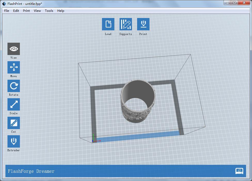
5 3. Software Operating Instructions Load into one or multiple files. Enter supporting editing mode View FlashPrint home screen from one of six viewing angles. Move model around on xy-plane; shift+click to move along z axis Turn and rotate your model Scale the size of your model Select right or left extruder you want to print with 3
6 Print it directly with your Dreamer or export to your SD card. To cut the model from different directions. You can use Flashprint software to control and perform printing tasks. 3.1 Load File You can load a model file or Gcode file into the software by following six methods: A. Click the Load button on top of the software interface. Then select the file which is needed for loading. B. Select the file which is needed for loading, and then drag the file to the interface of the software. C. Click the File -> Load File menu. Then select the file which is needed for loading. D. Click the File -> Examples menu. Then select the file which is needed for loading. E. Click the File -> Recent Files menu. Then select the file which is needed for loading. F. Select the file which is needed for loading, and then drag the file to the icon of the software. You can load into.stl,.obj,.fpp,.3mf,.png,.jpg,.jpeg,.slc or.bmp model files which are editable in the software. Please refer to Chapter 2.2~2.5 and you can find instructions of that modification, such as operations of mouse, changes of view from different angles and how to edit and save the file. After modification, please refer to Chapter 2.6 if you want to slice the model file, generate Gcode file and Print it. Important Note: Gcode file can not be edited any more, but you can directly start the printing after loading it into the software. Please refer to the Chapter and which tells you how to connect to Dreamer and how to print the Gcode file Generate Relievo Relievo is transformed from png, jpg, jpeg and bmp files. The png, jpg, jpeg or bmp file could be transformed into stl. file and loaded into the slice software for application. which includes settings for shape, mode, maximum thickness, base thickness, bottom thickness,width, height, top diameter,graphic pattern height and bottom diameter. Shape: including plane, tube, canister,lamp and seal. Mode: including darker is higher and lighter is higher. Maximum thickness: Z value of the model. Base thickness: The minimum raft thickness and the default value is 0.5mm. Width: X value of the model. Depth: Y value of the model. 4


7 Bottom thickness: For tube, canister and lamp to set up bottom thickness. Top diameter: For tube, canister and lamp to set up the top diameter. Bottom diameter: For tube, canister and lamp to set up the bottom diameter. Graphic pattern height: The maximum height of the stamped graphic pattern. The effect pictures for different shapes: The loaded original png picture: 5
 6")
8 (Plane) (Tube) 6

9 (Canister) (Lamp) 7

10 (Seal) 3.2 Mouse Operations Left click A. Select a model by moving the mouse to it and just left click it. B. Select multiple models by holding the Ctrl key and left click models you want. C. Model looks brighter when selected. D. Model can be edited when selected. E. Left click blank space to undo the selection of model Left click and hold the left button When changing the viewing angles or editing models, different effects appears by left-clicking and holding the left button. Please refer to Chapter 2.3.1~2.3.2 & Right click and hold the right button Same results in any operations when right clicking and holding the right button. Please refer to the Chapter & Scroll the mouse wheel Same effects in any operations when scrolling the mouse wheel. Please refer to the Chapter Change Views Change your view of the model by moving, rotating, scaling the view and so on Move You can move the view of printing frame in the software interface by following three ways: A. Long-press the left button of mouse and drag. B. Press and hold the middle button of mouse, and then drag the mouse. C. Hold the Shift key, long-press the right button of mouse and drag. 8
11 3.3.2 Rotate You can rotate the view of printing frame in the software interface by following two ways, A. Long-press the right button of mouse and drag. B. Hold the Shift key, long-press the left button of mouse and drag Scale You can scale the view of printing frame in the software interface by scrolling the mouse wheel in any condition Set You can set the view of printing frame in the software interface from six angels by following two ways to observe the model.(top/bottom/front/back/left/right View). A. Click the View menu, and then select the view you need to observe the model. B. Click the Look button on the left of the software interface, and select the view you need Reset A. Click the View menu, and then select Home view to reset the view. B. Click the Look button on the left of the software interface, and then click Reset button to reset it Show Model Outline Click the View -> Show Model Outline, it will highlight the outer surfaces of your model file with gray and white color Show Steep Overhang Click the View -> Show Steep Overhang menu. When the intersection angle between the model surface and horizontal line is within the overhang threshold value, we say the surface has steep overhang and it becomes red in the software. Overhang threshold value could be set as needed. The default value is 45 degree. 3.4 Edit Models You can edit the models by moving, rotating, scaling the model and so on Move When the model is selected, you can change model location on the build platform by the following two ways: A. Click Move button on the left of the software interface. Long-press the left button of mouse and drag, you could adjust the location of the model in XY direction. Hold the shift key, and long-press the left button of mouse and drag, you can adjust the location of the model in Z direction. You can see the distance and direction of the movement which refers to the relative distance between present and former location. B. Click Move button on the left of the software interface and then enter the distance value you want to move on X/Y/Z axes positioning. Click Reset button to reset distance values. 9
12 Note: Generally, we suggest you to click the Center and On Platform buttons after adjusting location of the model to make sure the model within the printing scope and sticking to HBP. Only click On Platform button if you want to print the model in a specified position Rotate When the model is selected, you can change the orientation of your model on the build platform by following two ways: A. Click Rotate button on the left of the software interface and you can find three mutually perpendicular rings whose color is red, green and blue. Click one ring and rotate on the present axis, you will see the rotation angle and direction in the center of circle. In this way, you could make the model rotate on X/Y/Z axis. B. Click the Rotate button on the left of the software interface, and then enter into rotating angel values in X/Y/Z axes positioning. Click Reset button to reset rotating angel values Set side flat After choosing model, operate as below to set side flat check Rotate->Set side flat ; Choose the side of model by mouse, double click the left mouse button on mouse floating side, the model side will be automatically set as flat, the selected side will plying-up bottom board Scale When the model is selected, you could change the size of the model on the build platform by the following two ways. A. Click Scale button on the left of the software interface, then press the left button and move the mouse to adjust the size of the model. You will see corresponding values of different axes near the borders. 10

13 B. Click Scale button on the left of the software interface, and then enter into scale values in X/Y/Z axes positioning. Click Maximum button to get largest size possible for building. Click Reset button to reset the size of model. Note: Select Uniform Scaling option, it will scale the model in equal proportion when changing value in any positioning of the model. Not select this option, it will only change the value of the corresponding positioning Set When the model is selected, click Extruder button on the left of the software interface and select the extruder you want to print with. The model will turn purple if you choose left extruder or gray if right extruder. If you choose Flashforge Finder/Guider, the software will be unavailable for nozzle setting and the default nozzle setting shall be Right Nozzle. If a model can be printed with dual extruders or the support is needed to complete the printing, you can use dual extruders to print it with different color filaments or even different kinds of filament. However, dual extrusion printing is not available when the model can only be printed with one extruder. You need to know whether the model diagraph has single or dual colors when selecting the model. Dual-color model is combined with two single color models. Note: When setting the extruder, mouse operations are same as those of changing views. Please refer to the Chapter 2.3.1~ Cutting the Model: Left-click to select the target model and then click the [Cut] icon on the left to enter the Cut mode(shown as follows). Users can set up the direction(free-hand plane, X plane, Y plane, Z plane),position and keep parts in place. 11
 left-click to select the facet and hold down the left mouse button to drag the facet.")
![(2) change the position values, then click the [Start Cut] button or double-clickthe model.](/docs-images/87/95396844/images/14-1.jpg "(Before Cutting) (After Cutting) X, Y or Z Plane: Select the X, Y or Z plane in the Direction drop-down menu.")
 left-click to select the facet and hold down the left mouse button to drag the facet.")
14 Free-hand plane: Left-click to select the target model and hold down the left mouse button to draw the cutting line (The cutting line will turn into a facet later). To change the position of the facet, users can(1) left-click to select the facet and hold down the left mouse button to drag the facet. (2) change the position values, then click the [Start Cut] button or double-clickthe model. (Before Cutting) (After Cutting) X, Y or Z Plane: Select the X, Y or Z plane in the Direction drop-down menu. Left-click to select the target model and the software will automatically generate the facet according to the cutting position.to change the position of the facet, users can(1) left-click to select the facet and hold down the left mouse button to drag the facet. (2) change the position values, then click the [Start Cut] button or double-clickthe model. (Z Plane) Keep parts in place: After finished cutting, the new model will be in their original position won t be shifted automatically anymore. 12


15 (Contrast pictures:choosing function of keep parts in place or not) Others Undo Undo the most recent edit you made to your model file by following two ways: A. Click Edit-> Undo menu. B. Use the shortcut Ctrl+Z. Note: Selecting this option multiple times will continue to undo edits in reverse order in Which they were performed Redo Redo the most recent edit you have undone to your model file by following two ways: A. Click Edit-> Redo menu. B. Use the shortcut Ctrl+Y. Note: Selecting this option multiple times will continue to redo edits in reverse order in which they were removed Empty Undo-stack To clean up the recorded operating steps so as to release the memory Select ALL By the following two methods, you could select all models in the scene. A. Click Edit-> Select ALL menu. B. Use the shortcut Ctrl+A. Note: When models are too small to be seen or out of viewing scope, please click Center and On Platform buttons after selecting all models to bring them to the printing scope Duplicate After model is selected, you can duplicate it by the following two methods: A. Click the Edit-> Duplicate menu. B. Use the shortcut Ctrl+D Delete After model is selected, you can delete it by the following two methods: A. Click the Edit-> Delete menu. B. Use the shortcut Del Automatic put After loading one model or several models, press Edit->Automatic placing, all models will will be put in position according to the automatic put rule Mirror 13


16 To make mirror image in X-axis, Y-axis and Z-axis for the chosen model Model Repair The software will detect the model when loading the model. If any problem is detected, a dialog box will pop up for reminding the users. Users can click the Repair Model button or select the model, click [edit]--[model repairing] to repair the model Support Access support interface. 3.5 Edit Supports After model file is loaded, click Edit->Supports in the top menu, or press button in homepage, you can edit the support structures of your model. Click Back on the top-right corner to exit when finishing the edits. 14

17 3.5.1 Auto Supports Select this option to have your model build with support structures. FlashPrint software will automatically generate treelike, Linear, columnar support, and it will generate new support structures to replace original ones included in your model file Clear Supports Select this option to empty all the supports of your model. Click Edit->Undo in the menu or Ctrl+Z to undo this operation Add Select this option to add supports. After selecting this option, move the mouse to where you want to add the support, and then left-click the mouse to select the start point of support structure. Press and hold the left mouse button down, drag the mouse, and then you can preview the support structure you will add (If the support surface does not need to support or the angle of support column is too large, the previewed support structure will be highlighted.) Release the left button of mouse to add this support, the support structure will be generated according to the start and the end position. But if the support column intersects with the model or the previewed support structure is highlighted, support structure will not be generated Delete Select this option to delete supports. After selecting this option, move the mouse to the supports you want to delete, then left-click the mouse to delete it. Press Ctrl button and mouse left to delete support in region selection Support option FDM 3D Printer Click [Supports Options] and then a dialog box will pop up for supports type selection and parameter settings. Linear and treelike supports are available for selecting. If you select Treelike Supports, you can setup the parameters of overhang thresh, post diameter, base diameter and base height, and then click [OK] to confirm. If you select Linear Supports, you can setup overhang thresh and pillar size, then click [OK] to confirm, when choose Linear, output is Linear structure. If the model already has support, when you choose support type, the software will judge the existing support type and decide if it is necessary to delete these supports. It will jump out reminding, you can operate as you Need. (Note: Overhang thresh: To setup an angle value. If you input 45, then when it comes to a 3D model with an overhang of 45 or more than 45 degrees. The system will generate supports for these 15
 3.5.")
![5.2 DLP 3D Printer Click [Supports Options] and then a dialog box will pop up Columnar Supports.Included general and post size.](/docs-images/87/95396844/images/18-1.jpg "The general parameters:overhang thresh,post space, cross connection and exterior only.(note:overhang thresh: To setup an angle value.")

18 positions. The value extends from 30 to 60.Post diameter: The diameter of the treelike supports. The value range is 1-6mm. Base diameter: The diameter of the support raft. The value range is 3-10mm.Base height: The height of the support rafts. The value range is 1-6mm.Pillar size: The side length of the square column.) DLP 3D Printer Click [Supports Options] and then a dialog box will pop up Columnar Supports.Included general and post size. The general parameters:overhang thresh,post space, cross connection and exterior only.(note:overhang thresh: To setup an angle value. If you input 45, then when it comes to a 3D model with an overhang of 45 or more than 45 degrees. The system will generate supports for these positions. The value extends from 30 to 60. Point diameter: The diameter of the treelike supports. The value range is mm, and the value could not grater than post diameter value. Base height : the height of the support raft. The value range is 0-5mm. Base diameter: The diameter of the support raft. The value range is mm. Post spacing: The spacing among posts. The value range is 1-10mm. cross connection: connect adjacent supports by slash to add the strength and stability.external supports:generate supports which can contact with build plate only.) 3.6 New Project Click File -> New Project to create a new project. If your current project hasn t been saved with changes, it will pop up a dialog to prompt you to save them. Click Yes button to save those changes, click No button to discard them, Click Cancel button to close this dialog and it will not create a new project. 16


19 3.7 Saving File You can save changes of your model files by following two ways: A. Click File -> Save Project to save your file only with.fpp format. All the models(including supports) in a.fpp format file are independent and they can be edited again when reloading the file. Besides, extruders configuration and models locations remain same as saving the file. B. Click File -> Save As to save your file with.stl,.obj,.3mf or.fpp format. All the models in a.stl or.obj format file are not independent, but combined to a new model. Models locations remain same as saving the file, while extruders configuration becomes different when reloading the file.when a model with main part and support need to be saved, it is recommended to save the file as.fpp format. If you save the file as ".Stl", ".Obj"or".3mf", The model and the treelike supports in the plate are not independent of each other, while the model and the linear supports are independent of each other, the liner supports won t be saved with the model. The software will not be able to distinguish the original file model from the support and print Quality will be affected. 3.8 Printing Process Choose Machine Type Click Print-> Machine Type to choose the machine type you have before connecting to the printer, or the FlashPrint will automatically recognize the machine type after connecting, in this case you can not manual switch to other machine type(s). Different machine types have different machine frames which will affect sliced file(s) Connect Machine Please refer to Chapter for configurations of connecting to Dreamer 3D printer Print FDM 3D printer generate Gcode file In order to print, you need to slice the model file to generate gcode file. Configuring slicing Parameter and generating slicing files by following steps. 1. Click Print -> Print menu or Print button on top of the software interface, it will pop up a dialog box for slicing. If users choose Flashforge Dreamer/Flashforge Creator Pro/FlashForge Inventor, 17


20 the corresponding dialog box of slice parameters shall be figure 1,Optical materials are PLA, ABS,HIPS,conductive PLA and flexible material. If users choose Flashforge Finder/Guider/InventorII/GuiderII, the corresponding dialog box of slice parameters shall be figure 2,Optical materials are PLA, conductive PLA and flexible material. (figure 1) (figure 2) 2. Set slicing parameters and click Ok button, and it will pop up a dialog box for saving Gcode file. 3. In the Save as dialog box, select the path for saving the Gcode file, and then click Save button. You 18


21 can see the bar at the bottom of software interface start to show the completion progress of slicing, which means it is slicing and uploading Gcode file now. Click Abort button on the right side of the process bar to give up slicing Explanation of standard Slicing settings A.Floating boxes for slicing proper nouns:move the cursor to the specific position that a slicing proper noun or a parameter lies and linger for a while, a floating box will appear with the 19
22 explanation inside. B. Preview: Select this option to preview the Gcode file when slicing finished. C. Print When Slice Done: Select this option to directly print the model. D. Material Right: Choose filament type you want to print with right extruder. E. Material Left: Choose filament type you want to print with left extruder. Material Type:Select the appropriate nozzle and material according to the settings of nozzle. If users choose Flashforge Dreamer/Flashforge Creator Pro/FlashForge Inventor, select corresponding material for the left/right extruder. The material types include PLA, ABS,Soluble materials,conductive PLA and flexible material. If users choose Flashforge Finder/Guider, select corresponding material and the default material type is PLA,conductive PLA and flexible material. F. Supports: Used to hold the overhangs of model.choose Left or Right Extruder to print supports when overhang is existing, or Disable when no need. Click the [Supports] button, if the machine type is Flashforge Dreamer/Flashforge Creator Pro/FlashForge Inventor, select left/right extruder for supports adding. If the machine type is Flashforge Finder/Guider/InventorII/GuiderII, choose Able or Disable for raft setting. G. Raft: Creates a raft below the model which can help with adhesion and tolerance for non-perfect build plates. Choose Left or Right Extruder to print raft which can make the model attach well to the build plate, or Disable when no need. Click the [Raft] drop-down button, if it is Flashforge Dreamer/Flashforge Creator Pro/FlashForge Inventor, choose left/right extruder for raft setting. If it is Flashforge Finder/Guider/InventorII/GuiderII, choose Able or Disable for raft setting. H. Wall: Creates a wall around the model to scrape oozing from the idle extruder. It's suggested to enable in dual extrusion printing. I. Brim: Expand the outline of model s bottom layers to a Brim which helps anchor the edges of the model to the plate to avoid warping. J.Vase mode: When enabled, the interior infill and top solid infill will not printed. K. Resolution: When printing right extruder with ABS or dissolvable filament, you can select High option with better print but lower speed, or Standard option, or Low option with normal print but high speed. Each option has its own configured parameter. While printing right extruder with PLA filament, you have the fourth option, which is Hyper with hyperfine print. If users choose Flashforge Finder/Guider, users only need to set up the nozzle temperature according to the material. The nozzle temperature for PLA is recommended to be

 a.")
23 Click More Option button to set the parameters as you want. Different resolutions have different default parameters. Click Restore Defaults to restore it. A. Layers a. Layer Height :Thickness of each layer. The less thickness of layers, the more time will be used and the better model will be printed. b. First Layer Height: When printed with thinner layers, comparative thicker bottom layer could improve adhesion and tolerance for non-perfect build plates. B. Shell : Including outside shell quantity, sealing top layers, sealing bottom layers(when Vase model selected, sealing top layers invalid) a. Outside shell quantity:number of paths superimposed for building the shell, more paths make thicker shell. b. Sealing top layers: Number of solid layers on the upper surface of model. c. Sealing bottom layers: Number of solid layers on the under surface of model. C. Infill a. Fill Density :Determines the interior solidity of the model. b. Fill Pattern:Determines the infill pattern for the interior of model. Hexagon infill is with the highest strength while line infill is with the shortest print time. Triangle infill takes slightly more time than line infill, but with more cohesiveness between layers. c. Combine Infill: This option allows to combine infill and speed up your print by extruding thicker infill paths. If layer height is larger than 0.1mm, Every N Layers is suggested, otherwise, Every N Inner Layers is suggested. D. Speed a. Print Speed: Used to calculate movement speed during extrusion. The slower the speed is, 21

24 the more time will be used and the better model will be printed.. b. Travel Speed:Speed at which extruder moves when not extruding filament. Note: Recommend set the empty speed at 80, printing speed at 60 when use PLA, ABS and conductive PLA filament printing, use flexible material set empty speed at 70, printing speed at 20. Different model have different model parameter, several attempts to find the suitable Parameter. Different types of printing material and different quality of slice project, the speed value of configuration will be different, users can get the recommended values of different schemes in the default configuration. E. Temp. a. Extruder Set proper printing extruder temperature, according to material. The maximum temperature is 255 and the hint message will appeared when nozzle temperature is over 245.If the machine type is FlashFoge Dreamer/ FlashForge Creator Pro/ FlashForge Inventor dual extruder 3D printer, Users can set the temperature of dual extruder. As shown below: If the machine type is FlashForge Finder/FlashForge Guider/FlashForge InventorII/FlashForge GuiderII single extruder 3D printer, the setting interface as follow: b.set the temperature for left or right extruder and platform. Set 220 to the extruder temp for ABS,conductive PLA and flexible material printing. Set 50 to the platform temp for PLA,conductive PLA and flexible material printing,while 105 for ABS printing. Set (left: 240, right: 220)to the extruder temp for dissolvable Filament printing,set 105 to the platform temp.if users choose Flashforge Finder/Guider/InventorII/GuiderII, users only need to set up the nozzle temperature according to the material. The nozzle temperature for PLA is recommended to be 220, Conductive PLA and flexible material temperature is recommended to set at 230. Adjust the temperature according to the condition in order to get a good print. F. Others a. Cooling fan controls:set up the time to turn on the cooling fan. Only used for Dreamer/FlashForge Creator Pro/FlashForge Inventor at present. You can pre-set the height and make the cooling fan begin to work at the point. 22
. Then add the value, click [+] for confirmation, and the value will show in the list of [Delete Value].")
25 b.suspend at a Certain Point: Turn on the cooling fan when to specific height.users can add one or more specific height values(no higher than the model height). It displays as follows. Steps: Click the [Edit] button, and a box will pop up(see graphic below). Then add the value, click [+] for confirmation, and the value will show in the list of [Delete Value]. If deletion is required, select the specific value on the list and click [-] for confirmation. Click [OK] to finish and exit these steps Explanation of Expert Slicing settings 23

26 A. Preview: Select this option to preview the Gcode file when slicing finished. B. Print When Slice Done: Select this option to directly print the model. C. Select Profile: D. General: 1. Layer Highht: a. Layer Height: Thickness of each layer. The less thickness of layers, the more time will be used and the better model will be printed. b. First Layer Height: When printed with thinner layers, comparative thicker bottom layer could improve adhesion and tolerance for non-perfect build plates. 2. Speed: a. Base Print Speed: Base speed at which extruder moves during extrusion, which is the base value of subsequent speeds counting. b. Travel Speed: Speed at which extruder moves when not extruding filament. c. Minimum Speed:The minimum movement speed during extrusion.. d. First Layer Maximum Speed:To limit the print speed of first layer, which will help with adhesion. When enabling Raft, this limit will not apply. e. First Layer Maximum Travel Speed:To limit the travel speed of first layer, which will help with adhesion. When enabling Raft, this limit will not apply. 3. Temperature a. Extruder s temperature:extruder s temperature during printing. The maximum temperature is 255 and the hint message will appeared when nozzle temperature is over
27 b. Extruder and Platform:Appropriate temperature of build plate can improve adhesion and help large models avoid warping.if the machine type is Flashforge Dreamer/Flashforge Creator Pro/ FlashForge Inventor, it displays the temperatures of Left/Right Extruder and Platform. If the machine type is FlashForge Finder/Gudier/InventorII/GuiderII, it only displays the temperature of Extruder. Set temperature according to the filament type: Set the temperature for left or right extruder and platform. Set 220 to the extruder temp for ABS,conductive PLA and flexible material printing. Set 50 to the platform temp for PLA,conductive PLA and flexible material printing,while 105 for ABS printing. Set(left: 240, right: 220)to the extruder temp for dissolvable Filament printing,set 105 to the platform temp.if users choose Flashforge Finder/Guider/InventorII/GuiderII, users only need to set up the nozzle temperature according to the material. The nozzle temperature for PLA is Recommended to be 220, Conductive PLA and flexible material temperature is recommended to set at 230. Adjust the temperature according to the condition in order to get a good print. 4. Retraction a. Retraction length:length of filament to be pulled back into nozzle before extruder traveling or changing, which help prevent from stringing and oozing. b. Speed:Speed at which the filament is retracted. E. Perimeter: 1. Thickness: a. Shell Count:Number of paths superimposed for building the shell, more paths make thicker shell. b. Maximum Path Overlap:The maximum allowed overlap for perimeters inside a thin wall. 2. Start Points: a. Mode:Determines the rule of selecting layer start points.there are two options for Start Point mode. One is closest to specific location, the other is use random start points. Closest to specific location:all layer start points are aligned as close as possible to specified XY location. Use random start points:layer start points are randomly distributed all over the model. b. X :X-coordinate where all layer start points are aligned. c. Y :Y-coordinate where all layer start points are aligned. d. Permit optimize start points: Allow to adjust start points location when needed, which select a location as start poi nt except "closest to specific location". Suggest to select "No" when printing upright reliefs. 25
28 3. Speed: a. Exterior Speed:Percentage of Base Print Speed for printing outer-most perimeter. b. Visible Interior Speed:Percentage of Base Print Speed for printing inner perimeters which is visible when print done. c. Invisible Interior Speed:Percentage of Base Print Speed for printing inner perimeters which is invisible when print done. F. Infill: 1. General a. Top Solid Layers:Number of solid layers on the upper surface of model. b. Bottom Solid Layers:Number of solid layers on the under surface of model. c. Fill Density: Determines the interior solidity of the model. d. Fill Pattern:Determines the infill pattern for the interior of model. Hexagon infill is with the highest strength while line infill is with the shortest print time. Triangle infill takes slightly more time than line infill, but with more cohesiveness between layers. e. Start Angle:Determines the infill path direction of first layer, subsequent layers will turn 90 degree base previous layer. Hexagon infill is unaffected by this parameter. f. Overlap Perimeter:Percentage of extrusion width that will overlap between infill and perimeters. g. Vase Mode:When enabled, the interior infill and top solid infill will not printed. h. Cross angle: the angle between two adjacent infill layers path, which only support line infill mode. 2. Speed a. Solid Speed: Percentage of Base Print Speed for printing top and bottom solid infill. b. Sparse Speed: Percentage of Base Print Speed for printing interior infill. 3. Combine Infill a. Maximum Solid Combine Layers: This option allows to combine the overlapped infill to speed up printing. After combined, infill will be thicker while while the thickness of perimeter keeps unchanged. And the top/bottom combine layer height is not suggested more than 0.2mm. b. Maximum Sparse Combine Layers: This option allows to combine the overlapped infill to speed up printing. After combined, infill will be thicker while the thickness of perimeter keeps unchanged. And the inner combine layer height is not suggested more than 0.36mm. 4. Strength Infill a. Interval Layers :At regular intervals layer, force several solid layers to make model more solid. 0 means not activated. b. Solid Layers:The number of solid layers force added. 26
29 G.Support: 1.General a. Enable Support: Used to hold the overhangs of model.allows users to turn on/off the support option. Support structure can prevent the model from collapsing. If choosing Yes, then both treelike and linear supports are available for setting up. If choosing No, then both treelike and linear supports are unavailable for setting up. b. Select Extruder: Allows users to select the corresponding extruder. If the machine type is FlashForge Dreamer/FlashForge Creator Pro/ FlashForge Inventor, it s available for users to select extruder. If selecting Automatch, the software will select the extruder automatically depending on the extruder(s) used. If dual extruders are used, then the right extruder will be used for supports printing. If the machine type is FlashForge Finder/Gudier, it s unavailable for users to select extruder. 2.Treelike a. Speed: Percentage of Base Print Speed for printing treelike support. b. Space to Model(X/Y): Determines the minimum horizontal space between model and supports, which makes supports easier to be removed. c. Shell Count: Number of paths superimposed for building treelike support shell. More paths will generate a thicker skin. d. Lower build plate while traveling: lower the build plate while traveling to avoid extruder knocking down treelike supports. 3.Linear a. Speed: Percentage of Base Print Speed for printing linear supports. b. Space to Model(X/Y): Determines the minimum horizontal space between model and supports, which makes supports easier to be removed. c. Space to Model(Z): Determines the vertical space between model and supports, which makes supports easier to be removed. d. Path Space: Determines the space between adjacent support paths. Smaller space give finer surface supported, but take more time to print and against to supports Removing. e. Support Thickness:Setting higher thickness to get the more solid support, while lower thickness result in easy-remove support. f. Print Outline:print ountline of line support region or not? print outline to aviod the problem of incomplete region with line support, otherwise it is better to strip support. 27
30 H. Additions: 1.Raft: General: a. Enable Raft: Creates a raft below the model which can help with adhesion and tolerance for non-perfect build plates.enable to print raft during printing. Raft could help the model stick to the build plate. b. Select Extruder: is Allows users to select the corresponding extruder. If the machine type goes to FlashForge Dreamer/FlashForge Creator Pro/ FlashForge Inventor, it s available for users to select extruder, while the machine type goes to FlashForge Finder/Gudier/InventorII/GuiderII, it s unavailable for users to select extruder. c. Margin: Raft offset from the outline of the model s first layer. d. Space to Model(Z): Determines the vertical space between model and raft, which makes raft easier to be removed. Bottom layer: a. Speed:The higher layer height, the wider extrusion, the slower printing speed shoul d be chosen, or extruder will not be able to extrusion in time. b. Layer Height: Higher bottom layer height will improve adhesion for non-perfect build plates. When b uild plate temperature is high, the thicker raft also has better insulation. c. Path width:width makes it easier to paste raft to the build plate, but the wider path requires the lower printing speed. d. Fill density:the higher filling density, the more stable the raft will paste to build plate, the longer printing time. Middle layers: a. Layer Height: The thickness of middle raft (transition layers). b. Layers: The layers of middle raft (transition layers). c. Speed: The lower printing speed,the easier to paste transition layer on bottom layer,the more printing time it will take. Top layers: a. Layer Height: The thickness of middle raft (transition layers). b. Cross angle: The angle between top solid infill paths. c. Layers:The layers of top raft,when build plate temperature is higher than 110, it is recommended to print more layers to improve the thermal insulation. d. Speed:The lower speed, the better surface finish the top raft will have, the longer printing time. 2.Pre-extrusion a. Enable Pre-extrusion: Print an extra extrusion path before model printing. b. Margin: Determines the spacing between pre-extrusion path and the outline of the model s first layer. 28
31 c. Path Length: Determines the length of pre-extrusion path. d. Speed: The printing speed of pre-extrusion. 3.Wall a. Enable Wall: Creates a wall around the model to scrape oozing from the idle extruder. It's suggested to enable in dual extrusion printing. b. Select Extruder: Allows users to select the corresponding extruder. If the machine type goes to FlashForge Dreamer/FlashForge Creator Pro/ FlashForge Inventor, it s available for users to select extruder, while the machine type goes to FlashForge Finder/Gudier/InventorII/GuiderII, it s unavailable for users to select extruder. c. Shell Count: TNumber of paths superimposed for building wall. More paths will generate a higher strength wall but take more print time. d. Margin: Determines the spacing between model and wall. e. Speed: Speed at which the wall is printed. 4.Brim a. Enable brim: Expand the outline of model s bottom layers to a Brim which helps anchor the edges of the model to the plate to avoid warping. b. Select extruder: To select left extruder or right extruder if the machine type is FlashForge Dreamer/ FlashForge Creator Pro/ FlashForge Inventor ; If the machine type is FlashForge Finder/ Guider/InventorII/GuiderII there is no need to set extruder, the default extruder is right. c. Margin: The width of Brim, the wider brim is, the more stable it will be, the longer it will take. d. Brim layers:the more layer of brim the better anchoring the edges of the model, the harder to remove. e. Speed:The speed of brim printing. f. Don't generate Brim inside holes: Brim won t be generated inside holes, to avoid the difficulty of removing. I.Advanced 1.Stepper Motor Voltage(Usually keep default) a. X-Axis: Voltage parameter of X-axis stepper motor. The bigger the value is, the more powerful X-axis stepper motor is, but the more heater will produce. b. Y-Axis: Voltage parameter of Y-axis stepper motor. The bigger the value is, the more powerful Y-axis stepper motor is, but the more heater will produce. c. Z-Axis: Voltage parameter of Z-axis stepper motor. The bigger the value is, the more powerful Z-axis stepper motor is, but the more heater will produce. d. A-Axis: Voltage parameter of A-axis stepper motor. The bigger the value is, the more powerful A-axis stepper motor is, but the more heater will produce. e. B-Axis: Voltage parameter of B-axis stepper motor. The bigger the value is, the more powerful B-axis stepper motor is, but the more heater will produce. 29

32 2.Others a. Extrusion Ratio: Extrusion multiplier for all extrusion movements. b. Path Width: The width of extrusion path. The default value is 0.4mm which equals the diameter of nozzle c. Path Resolution: Determines the extrusion path resolution when model is over-detailed. The bigger the value is, the lower path coordinate resolution is. However, the extrusion precision will be higher. J.Others 1. Cooling Fan Controls a. Cooling Fan Controls:Set up the time to turn on the cooling fan.fan Status: Including Always On, Always Off, ON(when raft printed), ON(when to pre-set height), which only apply to Dreamer/FlashForge Creator Pro/FlashForge Inventor at present. b. The Pre-set Fan On Height: Turn on the cooling fan when to specific height. 2. Pause At Heights a. Pause Heights: Pause printing automatically when to specific heights.users can add one or more specific height values(no higher than the model height). It displays as follows Steps: Click the [Edit] button, and a box will pop up(see graphic below). Then add the value, click [+] for confirmation, and the value will show in the list of [Delete Value]. If deletion is required, select the specific value on the list and click [-] for confirmation. Click [OK] to finish and exit these steps. b. Edit Pause At Heights : Add or remove the Pause Heights. 3. Dimensional Adjustment a. Enable Adjustments: Adjust extrusion paths to compensate printing error. b. External Compensation: Adjust the model s outer diameter, set positive to enlarge 30

33 dimension and set negative to shrink dimension. c. Internal Compensation: Adjust the model s inner diameter, set positive to enlarge dimension and set negative to shrink dimension. 4. Rest extruder temperature once reach to specific heights a.exturder: Reset the temperature of extruder once reach to specific height. Edit the height value which needed to reset temperature, please don t over the model height.(when printing dual model file, please set left and right extruders)as shown below: b.edit: add or remove pause height Step: click edit button,enter into edit page(as shown below), edit reset height and temperature value, click + button to start setting,the added value will showed in delete reset height list. K. Save as new:allows users to save the model as a new file after parameter modification. How to do? After getting all the required parameters modified, click [Save as new], then a dialogue box will pop up. Users need to enter the file name into the box, then click [OK]. Click the drop-down menu of [Select Profile], the new added scheme can be found in the list. L. Remove Allows the users to delete the added scheme(s). Select one of the added schemes, click [Remove] and a dialogue box will pop up for confirmation. Click [Yes] to remove it or click [No] to cancel the current operation. M. Restore Default: Allows users to restore to the default settings. N. Save Configuration: Allows users to save the present configuration DLP 3D printer Hunter 3D printer Before printing, the model has to be sliced and generate Svgx printing file. Please refer to to learn how to generate Svgx files. Slicing parameter as shown below: 31
 as well as other parameters to save as a new material.")

34 1.Slicing parameter configuration a.print Preview: to select whether to enter into preview page. b.start to print after slice done: to select whether to start printing immediately after slice done. c.material type: there are several materials in the option, the default material is FH1100. The parameters have been ready for different materials. The Custom Material allows user to adjust the layer height ( mm) as well as other parameters to save as a new material. Layer height:the printing thickness of each layer. The default value is 0.025mm. prototyping time: Base time: the prototyping time of except layer, different photosensitive resin need different time, the default time is 3.0s, the range is 1.0s-60s. Attach time: the prototyping time: of model layer, different photosensitive resin need different time, the range is 1.0s-60s. Raft: the platform has been printed before print model, which help model to stick to the built plate.have enable mode and disable mode, while disable mode is easier to remove. size calibration: X calibration: when the printing size is different form the model size, users can set X calibration value to make up the errors form X axis.; default value 100%, range 50%-150%. Y calibration: when the printing size is different form the model size, users can set Y calibration value to make up the errors form Y axis.; default value 100%, range 50%-150%. Note: if there is big error between the printing size and model size, please contact the factory custom service. Infill: Infill density: set the degree of infill density, range is 0-100%. 32
35 Shell thickness: the thickness of model shells, range is 1.0mm-10.0mm. Infill thickness: the thickness of internal infill, range is 0.5mm-5.0mm. Others: Light intensity: adjust the light intensity of ray machine, different photosensitive resin would be different FDM 3D Printer Print Gcode File After finishing slicing, it will load into the generated Gcode file automatically if you select Preview option when slicing, or need you manually load into it and then go to preview interface. In the preview interface, there is a vertical scroll bar which shows each layer of the model and you can find Estimated Material Right and Estimated Print Time it costs on the top right corner. Then click Print button on the same location, the machine starts to print while click Back button to exit from Preview mode DLP 3D Printer Print Svgx File The operation of Svgx files is same with Gcode files, please refer to Pause or Terminate Printing Once printing starts, click the machine icon on the bottom right corner of the software interface and it will show the process status in a frame. Click Pause button to pause printing and then click Continue button to resume it. Click Stop button to cancel this printing task and you need to restart this print task if you want to print it again. Note: Please DO NOT click Pause button unless necessary, for it will affect printing result. 3.9 Printer Operations Connect / Disconnect You can connect Dreamer to Flashprint software via USB cable or WIFI. The machine icon on the bottom right corner of the software interface shows a broken chain pattern means disconnected, while shows a unbroken one means connected Connect A. USB cable connection a. Find USB ports on the right-side of machine and computer, plug in and connect. b. Open Flashprint software and turn on the printer. c. Click Print -> Connect Machine menu, then select USB in the Connection Mode option and select machine you want to connect in Select Machine option. If you can not find your machine, click Rescan button to scan your machine and select it. Finally click Connect button to connect to the printer. If you still can not find your machine after rescan, which means you haven t installed the driver in the software. You have to install the driver manually, please refer to the Chapter Normally, driver shall be installed automatically along with software. B. WIFI connection a. Via wireless network 1. Switch on the printer, and make the WIFI available by clicking the menu Tools ->Set up->wifi->wifi ON. 33
36 2. Turn on the WIFI and then connect the computer to the network whose name is the same as SSID.(It is the printer s default network without password if no settings have been made. ) 3. Open your browser and enter the IP address in the Address Bar. Then enter in admin as the account and password. (The above-mentioned IP address /Account /Password are default when the setting haven t been changed) 4. Enter the WIFI setting panel, select AP+STA mode for Dreamer, select AP or STA mode for Finder, then click [OK]. Note: Don t click [Restart]. (Note: If users only choose STA mode, it has the potential risk that Dreamer will fails WIFI connection forever once STA settings crash.) 34


37 5. Click STA Setting, and then click Scan button and choose a commonly used network. Type in password, save it, and then click Reboot to the printer seconds after the reboot, choose disconnect and try to connect WIFI again. Open FlashPrint, click the menu Print->Connect to select WIFI connection, and then enter the network IP address (same as the IP showed on the touchscreen) in the IP port option. Finally click connect to complete it. After this, you do not need to connect WIFI in the future if no WIFI setting is changed. If you want to change WIFI setting, please try the same way. b. Via wireless source set by the printer 35
 3.")
38 1. Switch on the printer, and make the WIFI available by clicking the menu Tools ->Set up->wifi->wifi ON. 2. Turn on the WIFI and then connect the computer to the network whose name is the same as SSID.(It is the printer s default network without password if no settings have been made. ) 3. menu Print -> Connect, and select Wi-Fi in the Connection Mode bar. Type in :8899 in the IP Address, Port bar, then click Connect button to complete it. Note: One printer could only have one connection. If printer is operating by another process, connections should be switched off firstly and try to connect again. If AP mode is chosen, the computer will be unable to go online by WIFI Disconnect from the printer Click Print -> Disconnect menu on top of the software interface, the computer will disconnect from the 3D printer Control Panel After connection between software and 3D printer is built, click Tools->Control Panel menu to open the control pane. Following operations are available in the control panel to control the printer. The control panels of different machine types are different. The control panel of Flashforge Dreamer/Flashforge Creator Pro/Flashforge Inventor shows in the control panel 1, while that of Flashforge Finder shows in the control panel 2,while that of Flashforge Guider shows in the control panel 3. (this function is only available to FDM 3D printer) (Control panel 1) 36


39 (Control panel 2) (Control panel 3) A. Jog Controls a. Jog Mode: You could set the distance the extruder or the platform moves by a single jog click time. b. Direction Buttons: These six blue-arrow buttons are set to control the movements on X/Y/Z directions. Click the direction buttons of x-axes and y-axes to control the horizontal movements of the extruder. Click the direction buttons of z-axes to control the vertical movements of the platform. Click X- button to make the extruder move to the left; click X+ button to make the extruder move to the right. Click Y- button to make the extruder move forward; click Y+ button to make the extruder move backward. Click Z- button to make the platform move upward; click Z+ button to make the platform move 37
40 downward.the distance of movement will be showed in the X/Y/Z value bar. c. Stop Button: Click this button to terminate current movement. d. Coordinate frame: It displays the coordinated positions of extruder and platform. e. Make current position zero button: Click this button to set the current position of the extruder and platform as the origin of coordinates. f. Center X/Y/Z button: Click these buttons to return the extruder or platform to the origin of coordinates automatically. g. X/Y/Z Speed sliding bar: Set the moving speed of the extruder and platform by sliding the speed sliding bar. B. Limit Switch In order to protect the 3D printer, there are three limit switches on X/Y/Z axes used to control the movement limited position. they have the following two statuses: a. Open Status: If the extruder or platform has not reached to the limit position of X/Y/Z direction, the switch won t be triggered and its status is Open. b. Triggered Status: If the extruder or the build plate moves to the maximum position, the maximum or the minimum limit switch of X/Y/Z axis will be triggered and shows Triggered according different machine types. C. Fan Controls Click Open button to turn on the cooling the fan, while Close button to turn it off. D. Stepper Motor Control It is used to control the stepper motor. Click Open button to lock the stepper motor and users can not adjust the position of extruder and platform manually, while Close button to unlock it and users can do manual adjustment on extruder and platform. E. LED Color The printer has a built-in LED, Click LED Color button to change its color built in the printer. F. Extruder Setting In the interface of extruder setting, you could feed in or withdraw the filament from the left/right extruder. By changing the value of Motor Speed (RPM), you could control the speed of feeding in and withdrawing filament. In addition, you could control the time of these actions through changing the value of Extrude duration. Generally, we suggest you set the extrude duration as 60s. Before feeding in or withdrawing the filament, the extruder should reach target temperature to melt the filament before you click Forward / Reverse button to start these operations. For ABS filament, target temperature of extruder is 220 ; for PLA filament, target temperature of extruder is

41 for dissolvable Filament filament, target temperature of extruder is 240. Click Stop button to stop feeding in or withdrawing filaments. G. Temperature Control Type in the target temperature in the left blank and click Apply button to heat the extruder or platform. The printer starts to heat the extruder or the platform, and you will see the actual temperature the extruder or platform has reached on the right and a temperature changing table with 3 different color curve line below. Note: The printer will heat platform firstly to reach target temperature and then heat extruders when both are needed to heat. H. Filament Detection To detect whether the filament is loaded in Finder. L. Servo Control To control the servo s on-off Firmware Upgrade The software will check and download updates automatically when users open it, and remind users to upgrade to new version if available. Ways to install firmware as follows,finder 3D printer must connect computer with USB cable before update firmware(this function is only available to FDM 3D printer): A. Disconnect the computer and printer, or Click Tools -> Update Firmware menu and select Disconnect option, B. Select your machine type and corresponding firmware in the popped up dialog and then click Ok to upgrade. If the machine is idle, it will start to upgrade to new firmware On Board Preferences When the printer has been connected, click Tools-> On Board Preferences menu to review the configuration of mother board including Machine Name, and Extruder count etc. When choosing extruder count as 2, Extruders Distance option is available. Users can modify the X/Y distance between the extruders as need.the X/Y distance refers to the distance of X or Y directions between the two extruders.if it is Flashforge Finder/Guider, the content only includes the name of the machine.(this function is only 39


42 available to FDM 3D printer) Machine Information When the printer has been connected, click Tools->Machine Information menu to review the information about the machine, including MACHINE TYPE, MACHINE NAME, FIRMWARE VERSION, etc. (this function is only available to FDM 3D printer) Driver Installation A. Open the root directory of the software. (e.g. C:\Program Files\flashforge\FlashPrint) B. Open the driver folder which in the root directory and find the driver. There are two driver installation packages, please install one of them according to your computer system. For 64bit edition, please install dpinst_amd64.exe file; while for 32bit edition, please install dpinst_x86.exe file. (this function is only available to FDM 3D printer) 3.10 Others Preferences Click File-> Preferences menu to select the interface language and etc. 1. General A. Language So far this software supports English, Japanese, Simplified Chinese,Traditional Chinese,French, Korean,Russian. B. Check for Update after Startup Select Yes option to command the software auto-check updates after starting up it. The software will remind you to update to new version when it is available after checking. C.Font Size Use to setting the font size of the software.large,middle and Small front mode to choose. If 'font size' chose 'large', the software font is large font mode.if you choose middle mode, the front of software is middle.otherwise is small font mode. The default font size is small font size. 2. Print 40
![D.Auto-layout newly-imported model To setup the model s position and posture. If you select [Yes], the model will be on the platform and auto-centered when you load the model.](/docs-images/87/95396844/images/43-0.jpg "If you select [No], the model will maintain its initial position and posture when you load the model. E. Expert Mode Expert Mode grants the users more freedom of parameter edition.")
43 D.Auto-layout newly-imported model To setup the model s position and posture. If you select [Yes], the model will be on the platform and auto-centered when you load the model. If you select [No], the model will maintain its initial position and posture when you load the model. E. Expert Mode Expert Mode grants the users more freedom of parameter edition. There are two modes are available for users, one is Basic Mode and the other is Expert Mode. F. Performence extruder It is the setting to save the choice of performence extruder, which is only for Flashforge Creator Pro and Flashforge Dreamer. According to 3D printer condition and usage habit, user can set the performence extrude. Extruder choosing will not needed before silcing.(this function is only available to FDM 3D printer) Help Contents Click Help-> Help Contents menu to be directed to online user manual Check for Updates A. Automatic Update Refer to to set auto update.click button of skip this version, you can skip the update. B. Manual Update Click Help-> Check for Updates menu to check new version of software online. If there is an updated version of the software to be detected, it will pop up a new version of update dairy, according to their own needs users can download and install the updated version or close the prompt. 1.1~1.2 to install the software First time user guide An explanatory menu pops up the first time you open Flashprint. Click Continue to learn more about the features, or close the menu if you re already familiar with the features. You can go to Help -> First time user guide to re-open the menu when you need to learn the features Later. 41


44 Software Information Click Help-> About FlashPrint menu to review information about the software, including software version and copyrights, update log etc. 42
Advanced Printing. This article will take you to get to know the advanced printing skills.
 Advanced Printing This article will take you to get to know the advanced printing skills. There are two modes are available for users, one is Basic Mode and the other is Expert Mode. Expert Mode grants
ideamaker Manual
 ideamaker Manual Using ideamaker... 2 Basic information... 2 What is ideamaker?... 2 Where to download ideamaker?... 2 Install ideamaker... 3 Let s Print!... 6 How to use ideamaker?... 23 Interface...
PowerSpec Ultra 3D Printer Start-up Guide Table of Contents
 PowerSpec Ultra 3D Printer Start-up Guide Table of Contents 1 What's Included in the Box?...Page 3 2 Un-boxing.Page 4 3 Initial Hardware Installation Page 6 4 Software Instruction.Page 8 5 Filament Page
Cura (Documentation for version )
") Cura (Documentation for version 15.04.06) Getting Started Installation To start the installation of Cura, download it first. After downloading, open the installer and run the installation wizard to complete
Cura (Documentation for version 15.04.06) Getting Started Installation To start the installation of Cura, download it first. After downloading, open the installer and run the installation wizard to complete
ideamaker Manual
 ideamaker Manual www.raise3d.com 1 Using ideamaker... 3 1.1 What is ideamaker?... 3 1.2 Where to download ideamaker?... 3 2 Install ideamaker... 4 3 Let s Print!... 9 3.1 Import.STL files... 9 3.2 Slice
Dreamer Series User Manual
 Dreamer Series User Manual Welcome to the world of the Dreamer. To ensure that you have the best possible user experience, it s important that you follow this user manual. Let s get started! In Parts I
ideamaker Manual
 ideamaker Manual www.raise3d.com 1 Using ideamaker... 3 1.1 What is ideamaker?... 3 1.2 Where to download ideamaker?... 3 2 Install ideamaker... 4 3 Let s Print!... 9 3.1 Import.STL files... 9 3.2 Slice
Dremel Digilab 3D Slicer Software
 Dremel Digilab 3D Slicer Software Dremel Digilab 3D Slicer prepares your model for 3D printing. For novices, it makes it easy to get great results. For experts, there are over 200 settings to adjust to
MP Education Guider II 3D Printer
 MP Education Guider II 3D Printer P/N 30527 User's Manual CONTENTS SAFETY WARNINGS AND GUIDELINES... 5 CUSTOMER SERVICE... 6 PACKAGE CONTENTS... 6 PRODUCT OVERVIEW... 8 Front View... 8 Top View... 8 Right
MP Education Inventor II 3D Printer
 MP Education Inventor II 3D Printer P/N 30525 User's Manual CONTENTS SAFETY WARNINGS AND GUIDELINES... 5 CUSTOMER SERVICE... 6 PACKAGE CONTENTS... 6 PRODUCT OVERVIEW... 8 Front View... 8 Top View... 8
MP Education Inventor 3D Printer
 MP Education Inventor 3D Printer P/N 30526 User's Manual CONTENTS SAFETY WARNINGS AND GUIDELINES... 5 CUSTOMER SERVICE... 6 PACKAGE CONTENTS... 7 Tool Box Contents:... 8 Accessory Kit Contents:... 8 PRODUCT
3-7. Set Materials (Touch Screen) Set Materials (Software) Material Weight adjustment (grams) Current material weight. Increase.
 Set Materials (Software) Material Weight adjustment (grams) Current material weight. Increase.") Set Materials (Touch Screen) 3-7 Decrease Material Weight adjustment (grams) Increase Current material weight Save current settings Stop extrusion and heating Back withdraw material change material extrude
Set Materials (Touch Screen) 3-7 Decrease Material Weight adjustment (grams) Increase Current material weight Save current settings Stop extrusion and heating Back withdraw material change material extrude
Easy use of Repetier-Host software
 Easy use of Repetier-Host software Examples base on version Repetier-Host 1.06 1. Repetier-Host overview Repetier Host is an easy to use software for 3D printing. The main functions include manual debugging
User Guide. Finder Desktop 3D Printer
 User Guide Finder Desktop 3D Printer V1.0 17.6.2015 Contents Welcome to Flashforge Finder A. Overview B. Acknowledgment and Commitments C. About 3D Printing Chapter 1. Set up Your Finder A. Unpacking
Figure 1: Diagram of a 3D printer. You can find the most up-to-date version of this manual in electronic format on our website:
 INTRODUCTION What is a 3D printer? A 3D printer (see Figure 1) is a device that is able to create solid three-dimensional objects using a design produced on a computer. Currently, there are various technologies
USER MANUAL Unique BotApp Ware Ware Bot Bot Bot Dual 2 Bot Bot Filament
 USER MANUAL Unique Ware USER MANUAL Unique Ware 2 TABLE OF CONTENTS 1 INTRODUCTION 4 2 INSTALLATION AND GETTING STARTED 4 2.1 DOWNLOAD AND INSTALL THE CRAFTWARE SOFTWARE 4 2.2 OPEN THE CRAFTWARE SOFTWARE
Selective Space Structures Manual
 Selective Space Structures Manual February 2017 CONTENTS 1 Contents 1 Overview and Concept 4 1.1 General Concept........................... 4 1.2 Modules................................ 6 2 The 3S Generator
DP200/DP201/DP102 Series. Slicer Program Manual
 DP200/DP201/DP102 Series Slicer Program Manual Read the User Manual before operating the product, and keep the manual at a convenient place near the product. Contents 1. Slicer Program Manual-----------------------------------------------------------------------------------------------------3
Laser Machine User Manual:
 Laser Machine User Manual: OPERATOR ( EasyCut / LaserCut version 5.3 ) v1.0 CTR Laser Machine Operator Manual ( EasyCut version 5.3 ) ~ version 1.0 1 CONTENTS Section 1: Tutorials...5 1.1. How to Cut with
Set Up Your Print. Overview. The main interface has five components: 1. 3D Viewer
 Set Up Your Print Overview Open Uniz Desktop and click Control Bu on to show the 3D model viewer. The main interface has five components: 1. 3D Viewer https://uniz3d.com/support/supportsetprint/ 1/23 2.
2014 Simplify3D. Quick Start Guide
 Quick Start Guide Preparation Installing Simplify3D Software 3 The Configuration Assistant 4 The Interface Layout 5 3D Printing Workflow Import Process Settings Preview Print! Import 7 Process Settings
FlashForge Guider IIS 3D Printer User Guide
 FlashForge Guider IIS 3D Printer User Guide!NOTE Please read FlashForge Guide IIS 3D Printer User Guide carefully before use. Please well keep this User Guide for future reference. Content Content... 2
Instruction Manual. RS 3D Printer
 Instruction Manual RS 3D Printer 1) GENERAL This instruction manual contains important information regarding the installation, operation, maintenance and storage for RS 3D Printer. Please read these instructions
FlashForge Finder 3D Printer User Guide
 FlashForge Corporation FlashForge Finder 3D Printer User Guide Finder User Guide www.flashforge.com 0086-0579-82273989 Content Content... 2 Preface...3 Introduction... 4 Notice... 5 Chapter 1: 3D Printing
- Software KISSlicer Guide - [Z] ArrayZ C4C 3D Printer
![- Software KISSlicer Guide - [Z] ArrayZ C4C 3D Printer](/thumbs/92/108197208.jpg "- Software KISSlicer Guide - [Z] ArrayZ C4C 3D Printer") - Software KISSlicer Guide - ArrayZ C4C 3D Printer Software KISSlicer Guide We are suggesting customers using Kisslicer software as a 3D model slicing program, ArrayZ C4C 3D Printer has many feature is
- Software KISSlicer Guide - ArrayZ C4C 3D Printer Software KISSlicer Guide We are suggesting customers using Kisslicer software as a 3D model slicing program, ArrayZ C4C 3D Printer has many feature is
User Guide. Finder Desktop 3D Printer V Finder User Guide 1
 User Guide Finder Desktop 3D Printer Finder User Guide www.ff3dp.com 1 V2.0 20151013 Finder User Guide www.ff3dp.com 2 Content Acknowledgment...1 Commitment... 2 Introduction...3 About 3D Printing... 4
Virtual MODELA USER'S MANUAL
 Virtual MODELA USER'S MANUAL Virtual MODELA is a program that simulates the movement of the tool on the screen. Contents Contents Part 1 Introduction 1-1 System Requirements... 4 1-2 Overview of Virtual
Autodesk Fusion 360 Training: The Future of Making Things Attendee Guide
 Autodesk Fusion 360 Training: The Future of Making Things Attendee Guide Abstract After completing this workshop, you will have a basic understanding of editing 3D models using Autodesk Fusion 360 TM to
FlashForge Finder 3D Printer User Guide
 FlashForge Corporation FlashForge Finder 3D Printer User Guide Finder User Guide www.flashforge.com 0086-0579-82273989 Content Content... 2 Preface...3 Introduction... 4 Notice... 5 Chapter 1: 3D Printing
Repetier-Host Documentation for use with Kora Pro 3D PC
 Repetier-Host Documentation for use with Kora Pro 3D PC Installation Prerequisites Before you start with the installation, you should check if your computer meets the requirements. Currently available
UP! Quick Start Guide
 Personal Portable 3D Printer UP! www.pp3dp.com 1. Assemble Printer Open the box, take out the printer and accessories. Assemble the parts contained in the box as following procedure: 1. Unscrew the M4
Cura - DUET Dual Extrusion Setup
 SeeMeCNC Guides Written By: SeeMeCNC 2018 seemecnc.dozuki.com/ Page 1 of 15 INTRODUCTION Please note that dual extrusion is for advanced users. You should have some advanced knowledge on some G-Code and
Exercise Guide. Published: August MecSoft Corpotation
 VisualCAD Exercise Guide Published: August 2018 MecSoft Corpotation Copyright 1998-2018 VisualCAD 2018 Exercise Guide by Mecsoft Corporation User Notes: Contents 2 Table of Contents About this Guide 4
Autodesk Inventor Design Exercise 2: F1 Team Challenge Car Developed by Tim Varner Synergis Technologies
 Autodesk Inventor Design Exercise 2: F1 Team Challenge Car Developed by Tim Varner Synergis Technologies Tim Varner - 2004 The Inventor User Interface Command Panel Lists the commands that are currently
1.1 Software Overview. 1.2 Software Types
 1.1 Software Overview Aleph Objects, Inc., the maker of the LulzBot Mini, completely supports free/libre hardware and software. Along with the Mini being a free/libre hardware design, it has been tested
Design and Print Instruction Manual
 Diamond Design Design and Print Instruction Manual Contents Installation 1 Installing the Diamond Design Software 2-3 Installing the ORIGINAL Argox OS-214 printer drivers 4 Installing the EXCEL Argox OS-314
Slic3r User Guide. By Lorenzo Cantini (Kent s Strapper) and Ivan Bortolin Translation by Linda Anticoli 10/08/2012
 and Ivan Bortolin Translation by Linda Anticoli 10/08/2012") Slic3r User Guide By Lorenzo Cantini (Kent s Strapper) and Ivan Bortolin Translation by Linda Anticoli 10/08/2012 2 Contents Overview i 1 Installation and first run 1 1.1 Installation........................................
Slic3r User Guide By Lorenzo Cantini (Kent s Strapper) and Ivan Bortolin Translation by Linda Anticoli 10/08/2012 2 Contents Overview i 1 Installation and first run 1 1.1 Installation........................................
Technical Support: CUBE USER MANUAL
 CUBE THE DESKTOP 3D PRINTER USER MANUAL 2012-12-05 1 Contents 1 Installing software...3 1.1 Installing Python... 3 1.2 Installing ReplicatorG... 5 2 Pre-print checks...9 2.1 Power up...9 2.2 Connect to
SolidWorks Intro Part 1b
 SolidWorks Intro Part 1b Dave Touretzky and Susan Finger 1. Create a new part We ll create a CAD model of the 2 ½ D key fob below to make on the laser cutter. Select File New Templates IPSpart If the SolidWorks
Repetier-Host Documentation
 Repetier-Host Documentation Installation Prerequisites Before you start with the installation, you should check if your computer meets the requirements. Currently available computers should have no problems
4 TRANSFORMING OBJECTS
 4 TRANSFORMING OBJECTS Lesson overview In this lesson, you ll learn how to do the following: Add, edit, rename, and reorder artboards in an existing document. Navigate artboards. Select individual objects,
Repetier-Host Documentation
 Repetier-Host Documentation Installation Prerequisites Before you start with the installation, you should check if your computer meets the requirements. Currently available computers should have no problems
SolidWorks 2½D Parts
 SolidWorks 2½D Parts IDeATe Laser Micro Part 1b Dave Touretzky and Susan Finger 1. Create a new part In this lab, you ll create a CAD model of the 2 ½ D key fob below to make on the laser cutter. Select
To learn how to use Focus in Pix:
 Welcome To learn how to use Focus in Pix: Step-by-step guide Visit www.focusinpix.com/quick-guide for a quick overview of Focus in Pix software. You will also find many tips and tutorials on our site.
BFB Axon software manual
 Contents Install BFB Axon on your computer from the website for the latest version: www.bitsfrombytes.com > Downloads> Software. (Or from the SD card if supplied). If you are using Vista or windows 7,
Software Download. Slicing Settings (Advanced) Software Installation. Software Tutorial. Model Manipulation. Workflow .STL &.OBJ.
 Software Installation. Software Tutorial. Model Manipulation. Workflow .STL &.OBJ.") User Manual Ver.1 TABLE OF CONTENTS Software Download 2 Slicing Settings (Advanced) 8 DIAMETER Software Installation 2 SPEED TEMPERATURE Software Tutorial 3 Model Manipulation 9 ROTATION Workflow.STL &.OBJ
User Manual Ver.1 TABLE OF CONTENTS Software Download 2 Slicing Settings (Advanced) 8 DIAMETER Software Installation 2 SPEED TEMPERATURE Software Tutorial 3 Model Manipulation 9 ROTATION Workflow.STL &.OBJ
Flashforge InventorⅡ 3D Printer User Guide
 Flashforge Corporation Flashforge InventorⅡ 3D Printer User Guide InventorⅡ User Guide www.flashforge.com Content Content... 2 Preface...3 Introduction... 4 Notice... 5 Chapter 1: 3D Printing Technology...8
Basic Concepts. Launching MultiAd Creator. To Create an Alias. file://c:\documents and Settings\Gary Horrie\Local Settings\Temp\~hh81F9.
 Page 1 of 71 This section describes several common tasks that you'll need to know in order to use Creator successfully. Examples include launching Creator and opening, saving and closing Creator documents.
LinkMotion and CorelDraw 9, 10, 11, 12, X3, X4, X5, X6, X7 and X8:
 LinkMotion and CorelDraw 9, 10, 11, 12, X3, X4, X5, X6, X7 and X8: After you install LinkMotion software and set up all settings launch CorelDraw software. Important notes: Solustan s LinkMotion driver
Dr.Engrave USER'S MANUAL
 Dr.Engrave USER'S MANUAL This document is the operation manual for Dr. Engrave for Windows, a program for plate engraving. Contents Introduction... 4 Operating environment... 5 Overview of Dr.Engrave...
Piping Design. Site Map Preface Getting Started Basic Tasks Advanced Tasks Customizing Workbench Description Index
 Piping Design Site Map Preface Getting Started Basic Tasks Advanced Tasks Customizing Workbench Description Index Dassault Systèmes 1994-2001. All rights reserved. Site Map Piping Design member member
ZHEJIANG FLASHFORGE 3D TECHNOLOGY CO., LTD. Creator Pro Start-up Guide
 www.ff3dp.com ZHEJIANG FLASHFORGE 3D TECHNOLOGY CO., LTD. Creator Pro Start-up Guide www.ff3dp.com Contents 1 What's Included in the Box? 2 2 Un-boxing 2 3 Initial Hardware Installation 6 4 Software Installation
Pen & Ink Writer. User Guide
 Pen & Ink Writer User Guide 1 Table of Contents Pen & Ink Writer.....4 Pen & Ink Main Window...5 The Writing Area...9 Margins and Grids...12 Editing...13 Editing the Line Properties...13 Changing the Line
User Manual Version 1.1 January 2015
 User Manual Version 1.1 January 2015 - 2 / 112 - V1.1 Variegator... 7 Variegator Features... 7 1. Variable elements... 7 2. Static elements... 7 3. Element Manipulation... 7 4. Document Formats... 7 5.
ENJOY Introduction. Software Installation* Hardware. Calibration Settings. Print test. Appendex. Install print S/W Driver Install
 Quick Start Manual 1 ENJOY Introduction C O N T E N T S 6 5 Appendex 4 Print test 3 2 Hardware Calibration Settings Software Installation* Install print S/W Driver Install Hardware Intro Cable installation
The Institute for the Future of the Book presents. Sophie. Help. 24 June 2008 Sophie 1.0.3; build 31
 The Institute for the Future of the Book presents Sophie Help 1 24 June 2008 Sophie 1.0.3; build 31 1. Contents Working with Sophie 4 Sophie s interface 4 Halos and HUDs 4 Flaps, tabs, and palettes 9 The
We have two types of plastic printer (Makerbot and Up) and one powder printer at School of Architecture.
 and one powder printer at School of Architecture.") 3D printers are rapid prototyping tools which make solid, threedimensional objects out of melted plastic filament. Digital models are translated into instructions for the 3D printer (3d models are converted
3D printers are rapid prototyping tools which make solid, threedimensional objects out of melted plastic filament. Digital models are translated into instructions for the 3D printer (3d models are converted
Contents Contents...2 Preface...3 Introduction... 4 Notice... 4 Safety Notice... 5 Chapter 1: 3D Printing Technology...8 Chapter 2: Accessories...10 C
 www.ff3dp.com Flashforge UserCreator GuidePro 3D Creator Pro Desktop Printer User3D Printer Guide 1 Contents Contents...2 Preface...3 Introduction... 4 Notice... 4 Safety Notice... 5 Chapter 1: 3D Printing
6D Embroidery Software - Pretty Paisleys
 6D Embroidery Software - Pretty Paisleys By: Soni Grint Learn what type of picture is best to use for a background while digitizing these pretty paisleys. Adjust the picture as needed before placing stitches.
Geeetech Aluminum Prusa I3. User Manual
 Geeetech Aluminum Prusa I3 User Manual 1 Safety Instructions Building the printer will require a certain amount of physical dexterity, common sense and a thorough understanding of what you are doing. We
SI-100 Digital Microscope. User Manual
 SI-100 Digital Microscope User Manual Read this manual before use Keep for future reference Content 1 Introduction... 3 1.1 About The SI-100... 3 1.2 Advantage of SI-100... 3 1.3 Product Specification...
EASY INTERACTIVE WHITEBOARD
 EASY INTERACTIVE WHITEBOARD CONNECT COMPUTER/TURN ON PROJECTOR LAPTOP For the projectors in the labs, a computer is connected. These instructions are for you to connect a laptop computer to the projector.
StitchGraph User Guide V1.8
 StitchGraph User Guide V1.8 Thanks for buying StitchGraph: the easy way to create stitch layouts for hardanger and other complex embroidery stitch types. StitchGraph is intended to allow you to create
Contents escope Software Guide Execute Software Calibration and Measurement escope Software Interface Instructions Main Interface
 Contents escope Software Guide Execute Software...3 Capture Photo...3 Capture Video...3 Time-lapsed Picture / Video...4 Picture / Video Save as...4 Calibration and Measurement Calibration...5 Measurement...7
3D Printing Getting Started!
 ARCHITECTURE & LANDSCAPE ARCHITECTURE 3D Printing Getting Started! White filament is free to students for academic use. Where do I buy filament? NORTH DAKOTA STATE UNIVERSITY www.makerbot.com/store www.ultimachine.com/pla
Epilog Laser Cutter Instructions (Only the Essentials)
") Epilog Laser Cutter Instructions (Only the Essentials) How to export a file for SKETCHUP put it on the server, open it in Illustrator, and Prepare it for the Epilog Laser Cutter 1. In Sketchup: Draw a
Epilog Laser Cutter Instructions (Only the Essentials) How to export a file for SKETCHUP put it on the server, open it in Illustrator, and Prepare it for the Epilog Laser Cutter 1. In Sketchup: Draw a
Basic Modeling 1 Tekla Structures 12.0 Basic Training September 19, 2006
 Tekla Structures 12.0 Basic Training September 19, 2006 Copyright 2006 Tekla Corporation Contents Contents 3 1 5 1.1 Start Tekla Structures 6 1.2 Create a New Model BasicModel1 7 1.3 Create Grids 10 1.4
User Guide. for. JewelCAD Professional Version 2.0
 User Guide Page 1 of 121 User Guide for JewelCAD Professional Version 2.0-1 - User Guide Page 2 of 121 Table of Content 1. Introduction... 7 1.1. Purpose of this document... 7 2. Launch JewelCAD Professional
Brief 3ds max Shaping Tutorial
 Brief 3ds max Shaping Tutorial Part1: Power Key Axe Shaft Written by Maestro 1. Creation: Go to top view, create a 6 sided cylinder, 0.1 radius this is the perfect shaft thickness to fit in the hand, so
DA-CAD User Manual Dürkopp Adler AG
 DA-CAD 5000 User Manual DA-CAD 5000 All rights reserved No parts of this work may be reproduced in any form or by any means - graphic, electronic, or mechanical, including photocopying, recording, taping,
GCC vinyl cutter, cutting plotter for sign making
 Plotter Setup In "Plotter Setup," you can choose "Plotter List," "Environment," "Pen," and so on. [Plotter list] In this area, you can choose the machine type and set some basic information for your plotter
Spring 2011 Workshop ESSENTIALS OF 3D MODELING IN RHINOCEROS February 10 th 2011 S.R. Crown Hall Lower Core Computer Lab
 [1] Open Rhinoceros. PART 1 INTRODUCTION [4] Click and hold on the Boundary Lines in where they form a crossing and Drag from TOP RIGHT to BOTTOM LEFT to enable only the PERSPECTIVE VIEW. [2] When the
Guide: 3D Printing Software: UP, Makerbot P 1
 Guide: 3D Printing Software: UP, Makerbot 02-09-2015 P 1 Disclaimer P 2 We can t guarantee your model will successfully print as there are many factors which can affect it. The guideline will help you
Licom Systems Ltd., Training Course Notes. 3D Surface Creation
 , Training Course Notes Work Volume and Work Planes...........................1 Overview..........................................1 Work Volume....................................1 Work Plane......................................1
1. 3DWOX add-in program user manual
 . 3DWOX add-in program user manual Install Guide When 3DWOX add-in installation is complete, 3DWOX add-in tab will appear. While SolidWorks model is open, click Print 3D on the 3DWOX tab. 2 Solidworks
3D Prototyping X1 3D Printer. User Manual V1.3
 3D Printer User Manual V1.3 COPYRIGHT This document is copyrighted and contains proprietary information that is the property of 3D Prototyping Pty Ltd. The user does not have the right to copy, reproduce,
Lesson 1 Parametric Modeling Fundamentals
 1-1 Lesson 1 Parametric Modeling Fundamentals Create Simple Parametric Models. Understand the Basic Parametric Modeling Process. Create and Profile Rough Sketches. Understand the "Shape before size" approach.
User Guide Dreamer Desktop 3D Printer
 User Guide Dreamer Desktop 3D Printer Dreamer User Guide www.ff3dp.com 1 Dreamer User Guide www.ff3dp.com 2 CONTENTS WELCOME TO FLASHFORGE DREAMER A. How to use this manual B. The FlashForge Experience
Learning to use the drawing tools
 Create a blank slide This module was developed for Office 2000 and 2001, but although there are cosmetic changes in the appearance of some of the tools, the basic functionality is the same in Powerpoint
Google SketchUp. and SketchUp Pro 7. The book you need to succeed! CD-ROM Included! Kelly L. Murdock. Master SketchUp Pro 7 s tools and features
 CD-ROM Included! Free version of Google SketchUp 7 Trial version of Google SketchUp Pro 7 Chapter example files from the book Kelly L. Murdock Google SketchUp and SketchUp Pro 7 Master SketchUp Pro 7 s
FlashForge Hunter 3D Printer User Guide
 FlashForge Corporation FlashForge Hunter 3D Printer User Guide Hunter User Guide www.flashforge.com 0086-0579-82273989 Content Content... 2 Introduction... 5 Notice...6 Chapter 1: 3D Printing Technology...
Autodesk Inventor - Basics Tutorial Exercise 1
 Autodesk Inventor - Basics Tutorial Exercise 1 Launch Inventor Professional 2015 1. Start a New part. Depending on how Inventor was installed, using this icon may get you an Inch or Metric file. To be
Guide to WB Annotations
 Guide to WB Annotations 04 May 2016 Annotations are a powerful new feature added to Workbench v1.2.0 (Released May 2016) for placing text and symbols within wb_view tabs and windows. They enable generation
OrthoWin ShapeDesigner Manual V OrthoWin ShapeDesigner Software Manual
 OrthoWin ShapeDesigner Software Manual ORTHEMA Page 1 of 21 Content 1 Introduction...3 2 Menu prompting...3 3 Main window...4 4 File menu...5 4.1 New and Open...5 4.2 Save and Save As...5 4.3 Export to
Keynote 08 Basics Website:
 Website: http://etc.usf.edu/te/ Keynote is Apple's presentation application. Keynote is installed as part of the iwork suite, which also includes the word processing program Pages and the spreadsheet program
Geeetech Duplicator 5 3D printer. User Manual
 Geeetech Duplicator 5 3D printer User Manual Contents Safety Instructions... 4 1.Software Resources... 5 1.1 Repetier-Host... 5 1.2 Driver... 5 1.3 Arduino IDE... 6 2.Connect the Printer... 6 3.Printer
Cura: Basic 3D Printing Guide
 Cura: Basic 3D Printing Guide Introduction Cura is an open-source slicer, developed by Ultimaker, for use with FFF (Fused Filament Fabrication) printers such as the PrintrBot Play. A slicer analyzes your
Tutorial 1 Engraved Brass Plate R
 Getting Started With Tutorial 1 Engraved Brass Plate R4-090123 Table of Contents What is V-Carving?... 2 What the software allows you to do... 3 What file formats can be used?... 3 Getting Help... 3 Overview
2. Navigate to 3dsystems.com/shop/cubepro/downloads. Select Windows from the Software Download section at the bottom of the page.
 CubePro Software CubePro software is an easy-to-use tool that simplifies the printing process. The software is available by logging in to your http://3dsystems.com/shop account. Downloads are available
Microsoft Visio Working with Shapes
 Working with Visio Shapes Shape is the general term for the objects you will find on a stencil and objects created using the drawing tools. These include geometric shapes such as rectangles, triangles
Module 4A: Creating the 3D Model of Right and Oblique Pyramids
 Inventor (5) Module 4A: 4A- 1 Module 4A: Creating the 3D Model of Right and Oblique Pyramids In Module 4A, we will learn how to create 3D solid models of right-axis and oblique-axis pyramid (regular or
Chapter 12: Pull Toy - Solids and Transforms
 This tutorial demonstrates using solid primitives and simple transforms. You will learn how to: Enter coordinates to place points exactly. Draw a free-form curve and polygon. Create a pipe along a curve.
HAPPY HOLIDAYS PHOTO BORDER
 HAPPY HOLIDAYS PHOTO BORDER In this Photoshop tutorial, we ll learn how to create a simple and fun Happy Holidays winter photo border! Photoshop ships with some great snowflake shapes that we can use in
SMART Meeting Pro 4.2 personal license USER S GUIDE
 smarttech.com/docfeedback/170973 SMART Meeting Pro 4.2 personal license USER S GUIDE Product registration If you register your SMART product, we ll notify you of new features and software upgrades. Register
Profile Modeler Profile Modeler ( A SuperControl Product )
") Profile Modeler ( A SuperControl Product ) - 1 - Index Overview... 3 Terminology... 3 Launching the Application... 4 File Menu... 4 Loading a File:... 4 To Load Multiple Files:... 4 Clearing Loaded Files:...
Profile Modeler ( A SuperControl Product ) - 1 - Index Overview... 3 Terminology... 3 Launching the Application... 4 File Menu... 4 Loading a File:... 4 To Load Multiple Files:... 4 Clearing Loaded Files:...
5 Subdivision Surfaces
 5 Subdivision Surfaces In Maya, subdivision surfaces possess characteristics of both polygon and NURBS surface types. This hybrid surface type offers some features not offered by the other surface types.
Label Printing Software BA-300 Version 1.00
 Label Printing Software BA-300 Version 1.00 EN For Windows User s Guide What you can do with the BA-300 Application Using the BA-300 Application Troubleshooting Be sure to keep all user documentation handy
Flashforge Hunter 3D Printer User Guide
 Flashforge Corporation Flashforge Hunter 3D Printer User Guide Content Content... 2 Introduction... 5 Notice...6 Chapter 1: 3D Printing Technology... 9 1.1 Process...9 Chapter 2. About Hunter... 11 2.1
Artisan 1430 User's Guide
 Artisan 1430 User's Guide Artisan 1430 User's Guide Welcome to the Artisan 1430 User's Guide. Product Basics See these sections to learn about the basic features of your product. Printer Parts Locations
Software Manual. Revision 1.3
 Software Manual Revision 1.3 Copyright 2015 by Kudo3D. This material may be distributed only subject to the terms and conditions set forth in the Creative Commons Attribution-NonCommercial-NoDerivatives