Towards Passive 6D Reflectance Field Displays
|
|
|
- Bryan Hunt
- 6 years ago
- Views:
Transcription


1 Towards Passive 6D Reflectance Field Displays Martin Fuchs MPI Informatik Ramesh Raskar Mitsubishi Electric Research Laboratories Hans-Peter Seidel MPI Informatik Hendrik P. A. Lensch MPI Informatik Abstract Traditional flat screen displays present 2D images. 3D and 4D displays have been proposed making use of lenslet arrays to shape a fixed outgoing light field for horizontal or bidirectional parallax. In this article, we present different designs of multi-dimensional displays which passively react to the light of the environment behind. The prototypes physically implement a reflectance field and generate different light fields depending on the incident illumination, for example light falling through a window. We discretize the incident light field using an optical system, and modulate it with a 2D pattern, creating a flat display which is view and illuminationdependent. It is free from electronic components. For distant light and a fixed observer position, we demonstrate a passive optical configuration which directly renders a 4D reflectance field in the realworld illumination behind it. We further propose an optical setup that allows for projecting out different angular distributions depending on the incident light direction. Combining multiple of these devices we build a display that renders a 6D experience, where the incident 2D illumination influences the outgoing light field, both in the spatial and in the angular domain. Possible applications of this technology are time-dependent displays driven by sunlight, object virtualization and programmable light benders / ray blockers without moving parts. CR Categories: I.4.0 [Image Processing and Computer Vision]: General Image displays I.4.1 [Image Processing and Computer Vision]: Digitization and Image Capture Reflectance I.3.7 [Computer Graphics]: Three-Dimensional Graphics and Realism Color, shading, shadowing, and texture Keywords: passive reflectance field display, image-based relighting with natural light 1 Introduction For centuries, there has been technology available to create stained glass glass which emits a picture by modulating the incident illumination. In this article, we extend this concept to a new kind of displays that renders different images or even light fields depending on ambient illumination. The display for example can show a relightable scene model, rendering this scene in the illumination which is incident to the display from behind (see Figure 1), e.g. in natural lighting outside a window. Illumination dependent effects such as shadows and highlights will change accordingly. {mfuchs,hpseidel,lensch}@mpi-inf.mpg.de now at MIT Media Lab, [raskar]@media.mit.edu ACM, This is the author s version of the work. It is posted here by permission of ACM for your personal use. Not for redistribution. The definitive version was published in ACM Transactions on Graphics, VOL 27, ISS 3, 04 August area distant top red and green overcast time lapse Figure 1: A 4D reflectance field display (Design I) illuminated from behind with different incident directions and light source types. For the time lapse and overcast results, we taped the display to a window and recorded pictures with direct sun illumination and in overcast sky. Note how the highlights on the bottle cap and the shadows move as the illumination direction changes, and how the shadow boundary smoothes for the area light source. We propose a simple setup which produces these effects by optical means only. Our designs have been inspired by autostereoscopic displays, that produce view dependent images by placing a set of lenses on top of a pattern encoding the outgoing light field. In contrast to autostereoscopic displays, the output of our display depends on the incident illumination (see Figure 2). We describe an optical setup which changes the appearance depending on the illumination angle, and define a mechanism that superimposes the contributions from different angles, effectively computing an expensive integration with optical means. Using a simple configuration of optical components mainly lenses and lenslet arrays we discretize the 4D space of incident light rays, and embed it into a 2D plane in which a printed pattern performs a direction-dependent modulation. Another set of lenses then shapes the outgoing light field both in the angular or the spatial domain. The pattern can be quickly modified, for the efficient re-use of optical components. Our lens-based designs are considerably more light efficient than designs using slit masks. In particular, the following designs and prototypes are proposed: Design I: a 4D display, producing a 2D image depending on the 2D incident angular light distribution for a fixed observer (Section 4.1), Design II: an improvement of Design I for higher precision (Section 4.3) Design III: a 4D display that at one location modulates the 2D incident distribution, projecting out a different 2D angular distribution for each incident angle (Section 5.1), and Design IV: a 6D prototype which combines multiple 4D displays to modulate the incident light into a 4D light field, varying both in the angular and the spatial domain (Section 5.3). Both Design I and Design II have deficiencies with respect to con- 1

2 Figure 2: Display technologies: 2D displays are independent from viewer and light. A 4D light field display creates a parallax illusion of an object floating in space, while a 4D reflectance field display changes its flat appearance as its illumination changes. Combined, they become a 6D display: a display which creates a illumination-dependent light field rendering. trast and transmissivity, which we will discuss in Section 4.2. Still, they demonstrate the concept and are fully applicable in sunlight. Some of the possible applications of this technology are timevariant transmission in window sheets forming fully passive mood lights using the sun as light source. The displays can show timevariant pictures for natural illuminations. They can act as physical representations of captured 4D reflectance fields and environment mattes, which passively render the object of interest in the ambient illumination using passive optical components only. 2 Related Work Flattening of High Dimensional Visual Data High dimensional data structures play an important role in our everyday life: in images, volumes, light fields or reflectance field data sets. However, many optical visualizations and recording techniques are limited to a 2D structure. Therefore, methods have been presented in the past which address this problem by flattening the high dimensional data, embedding it in a planar, 2D representation. Integral photography [Lippmann 1908] is an early approach which records a 4D light field on a photographic plate. The main concept is adding an array of lenses to the plate, both discretizing the spatial coordinates of a (θ, x) representation and embedding the angular domain within. In recent years, this approach has been successfully applied to digital recording [Ng et al. 2005], with improved lens configurations [Georgiev et al. 2006], for microscopy [Levoy et al. 2006], and with flexible re-parameterization [Isaksen et al. 2000]. Veeraraghavan et al. [2007] have shown that a band-limited light field can also be embedded into sub-bands of the Fourier spectrum. Light fields can also be encoded in holograms [Ziegler et al. 2007], encoding the multidimensional information in a plane by exploiting phase variations in light wave fronts which are usually not perceived by human observers. Light Field Displays Planar encodings of light fields are since the days of integral photography closely coupled to the development of displays which create a 3D impression by projecting a light field into space. Nakajima et al. [2001] described a lens array on top of a computer display for a 3D viewing experience. In 2004, Matusik and Pfister [2004] presented an end-to-end system which records a 3D light field, streams it over the network and then displays it on a lenticular array screen. Their article also gives a good overview of current multi-dimensional display techniques. Javidi and Okano [2001] discusse a range of related techniques. Illumination-Variant Displays While light fields capture the appearance of a static object, reflectance fields [Debevec et al. 2000] further encode the optical response of an object to illumination. Nayar et al. [2004] presented a display which measures the distant room illumination, approximated as environment map, and interactively renders an image in this illumination. Koike and Naemura [2007] propose an extension towards emitting a light field in a similar fashion. Both displays are electronic and rely on software and hardware evaluating the illumination and rendering the reflectance field. Scharstein et al. [1996] obtained a patent on a device which is passive: it employs optics in order to create a numeral display of the current time. This is achieved by encoding a pattern in a slit mask so that natural sunlight direction produces different symbols. However, this construction inherently blocks the majority of incident light rays. In this article, we also follow a passive approach to illuminationvariant displays, but, in contrast to Scharstein et al., we use lenses and colored patterns, thus using a larger portion of the available light for a higher contrast display of more expressive patterns. 3 Overview The display types we propose in this article modulate the incident light field both spatially and angularly. This process of modulating an incident light field into a different output light field can be thought of as a particular reflection function, expressed by a reflectance field [Debevec et al. 2000]. In our case, the incident light is assumed to be distant, simplifying the reflectance field to a 6D function R(x out, ω out, ω in), which depends on the incident angle ω in and the outgoing ray (x out, ω out). The mapping from an incident, distant light field L(ω in) to a radiant light field L(x out, ω out) is given by L(x out, ω out) = R(x out, ω out, ω in) L(ω in)dω in. (1) Ω Our displays implement the reflectance function physically, using only passive optical elements. They operate on real-world illumination incident from behind the display and transmit a controlled, modified light field. We present a low-resolution 6D reflectance field display in Section 5.3, and reduce the dimensionality of the reflectance field for the other prototypes by creating the same image for all observer positions (Section 4.1), or causing only angular but no spatial variation (Section 5.1). All of the different designs make use of common building blocks, which are inspired by previous integral photography approaches. 2
 are distributed according to the hexagonal lattice arrangement of the lenslet array.")

3 Figure 3: After discretizing, a 4D pattern is embedded into a 2D image (left): macro-pixels capture the variation along the spatial coordinates (x, y), within, micro-pixels vary according to (θ, φ). To the right, the cap of the bottle shown in Figure 1 is displayed. (x, y) are distributed according to the hexagonal lattice arrangement of the lenslet array. Figure 5: Design I : As the incident light angle changes, the transmissivity of pixels changes. For sufficiently small angles, the individual contributions on the diffuser plane overlap. Figure 6: 4D construction for the display from Figure 1, with separated layers. (Design I) Figure 4: Lens array technology has been used by the integral photography approach to modulate the light field emitted by the display. We propose a modulation according to the illumination angle. The n-dimensional reflectance function is first discretized and then flattened into a 2D plane, trading the spatial resolution in the plane for encoding both the angular and the spatial variation in various dimensions (see Figure 3). Each location p within this plane encodes exactly one sample of the reflectance field. Each point is responsible for the modulation of the light transport for one particular incident direction and one outgoing ray (x out, ω out, ω in). The modulation is carried out physically by letting the incident light field shine through a printed transparency. Printing a different pattern will realize a different reflectance field. The second common component of our designs is a set of lenses or lenslet arrays which have the task of discretizing and mapping the incident and the reflected light field to the corresponding locations in the plane. 4 Observer-Invariant displays On the way to a full 6D display, we introduce observer-invariant displays (Design I and Design II), that output pictures varying with the incident illumination, but display the same 2D picture for any observer position, providing a 4D viewing experience. Extensions to observer-variant displays will be discussed in Section Design I In order to flatten the 4D reflectance field into a plane, we discretize the spatial dimensions (x, y) into macro-pixels, and, within each macro-pixel, encode the angular variation along (θ in, φ in) in micro-pixels, as illustrated in Figure 3. For guiding the incident light directions to be modulated by the correct micro- and macro-pixel the incident light field is discretized and mapped to this planar representation as well. We apply the same concept as used in integral photography, and use a lens array for this task (see Figure 4). While in traditional light field displays the lenslet array dispatches the different 4D viewing rays into a 2D plane we use them to guide the incident light rays to specific locations depending on the light direction. In our case, each lens corresponds to a final macro-pixel, i.e. it will correspond to one pixel as seen by the observer. Assuming a distant, parallel light beam, the lens focuses the light onto a single spot in its focal plane behind the lens. The location of the spot, however, will move depending on the angle of incidence, which is exactly the behavior required to produce the mapping. The printed transparency is placed in the focus plane. It modulates the color and attenuates the intensity only of that light beam which hits the lens from the corresponding direction. After the modulation the beam again diverges, illuminating a pixel-sized spot on the diffuser surface. Figure 5 illustrates this design. 1 A parallel light beam hits an array of lenses (A), which focuses the light on a plane with an embedded pattern (B), flattening the 4D field. Depending on the angular direction and the spatial position, the transparency then modulates the incident light beam with a R(x, ω in) reflectance field. In order to provide a view independent experience a diffuser surface (C) is added. It ensures that the modulated beam can be observed from a wide range of viewing angles. Furthermore, it physically integrates over all incoming directions of one macro-pixel as illustrated in Figure 5. Thus, the setup physically evaluates the rendering equation (Eq. 1) in real-time. 4.2 Results for Design I We have implemented a prototype display, which consists of five components (Figure 6): an inexpensive hexagonal lens array (Fres- 1 The ray diagrams are to be read from left-to-right from the light source to the observer. For clarity, we always draw a 2D cut through the 4D field and align x with the horizontal axis. In our drawings, we indicate conjugateness for relevant planes by drawing a colored bracket, so that a dotted line indicates the plane where the lens lies, and two arrows indicate the conjugate planes. In cases where one plane is the focal plane of the lens, we label the opposite arrow with infinity. While in our experiments, we modulate the light field with different colors and varying attenuation, we illustrate the patterns in the ray diagrams either fully transparent or fully opaque in order to prevent additional visual clutter. 3
, display with high-contrast pattern without any diffusers (b), with Intellicoat diffuser (c),")
 keeps the modulated light cones from moving, generating a precise overlap on the")
4 transmissivity 60 % 28 % 18 % 61 % 37 % contrast in dark room 223 : 1 80 : 1 84 : : : 1 contrast with front ill. 88 : : : : 1 12 : 1 Figure 7: Design I: Transmissivity and contrast experiment: background illumination (a), display with high-contrast pattern without any diffusers (b), with Intellicoat diffuser (c), Intellicoat and 3M (d), holographic diffuser (e), holographic diffuser and 3M (f). Top row: light box in dark room, bottom row: front illumination added. Figure 8: Design II: Adding a lens array with half the focal length of the main lenses in the pattern plane (B) keeps the modulated light cones from moving, generating a precise overlap on the diffuser. For steeper angles, a wrap-over into the next lenslet can still occur. nel Technologies Inc., lenses per cm 2, focal length 3 mm), a printed transparency (using an Epson Stylus Pro 4800 printer set to dpi resolution), a plastic spacer, a diffuser sheet (Intellicoat Technologies DMBF5UV), and a selectively transmissive sheet (see below). In order to improve contrast, we printed a mirrored version on a second transparency and mounted them back-toback, which is a technique occasionally found in commercial printing. Transparent plastic sheets maintain equal distance between the transparency and the diffuser sheet. The distance is chosen to level sharpness and anti-aliasing. We encoded the reflectance field of a bottle into the pattern, which is shown in Figure 3. Details of this process will be found in Section 6. Unfortunately, the diffuser screen does not only scatter the illumination along the intended light path, i.e. from the back, but integrates all light from the viewer side as well. This drastically reduces the achievable contrast. This effect can be partially reduced by adding a Notebook Privacy Computer Filter by 3M to the observer side. It is a thin, transparent sheet, which largely reduces transmission for non-normal viewing angles. Still, the best result is achieved with either direct sunlight as back-illumination, or with an artificial light source in an otherwise darkened room. Preliminary experiments with a 30 degrees light shaping holographic diffuser screen from BFi OPTiLAS suggest possible efficiency and contrast gains (see Figure 7). The best material combination will heavily depend on the specific application case. Figure 1 summarizes the results obtained in various settings, e.g. illuminated with point and area light sources in a darkened lab. The figure further shows the display mounted to an office window for different sky light conditions. As the light direction changes, highlights and shadows of our rendering move in real-time as a result of the optical computation. The point light sources produce crisp and correctly moving highlights. Illuminating with a red and a green light bulb, one sees how the display integrates simultaneously over different light source directions, resulting in separate red or green highlights but rendering the table top in yellow. The contrast in the window setting is slightly reduced. The overall image resolution is limited to the resolution of the lens array. One can further make out some small blur in the overcast illumination and in the area light source setting. As explained in the next section, without a corrective lens layer, the rendered images tend to shift slightly on the diffuse plane as the incident light direction changes. 4.3 Design II with Correcting Lenses Figure 5 also demonstrates one shortcoming of this simple design. On the diffuser, the modulated beams of one macro-pixel are not perfectly aligned, but only overlap partially. In the worst case, even Figure 9: Design II for a small display, with top half of housing removed. contributions from neighboring macro-pixels are combined. This can be corrected by an improved design (Figure 8), where a second array of lenses is introduced in plane (B). Their task is to project the image of the respective main lens on the diffuser surface. This implies that planes (C) and (A) are conjugate with respect to the corrective lens arrays, and their focal length must therefore be half the focal length of the main lens. If the main lenses are plano-convex, we can re-use parts with the same specification in (B), putting them back-to-back and embedding the pattern in-between. This additional lens array guarantees a one-to-one mapping between the macro-pixel observed at (C) and its corresponding lenslet in (A). Overlap to a neighboring pixel can only occur if the diffuser plane is moved, or if the incident angle is so steep that the beam through one lens in (A) will hit the neighboring macro-pixel in (B) (see Figure 8). 4.4 Results for Design II The second prototype display includes this corrective lens array. Since it involves more parts of higher optical quality and precision, we have manufactured a prototype of smaller resolution. The setup is depicted in Figure 9. This time, we use a plano-convex lens array with 25 mm 25 mm edge length and 6 5 lenses of a focal length of 10.5 mm as primary lenses in plane (A), and two lens arrays of that type as correction layer in plane (B). They are made of glass by Moulded Optics GmbH. We use the same diffuser as in the first prototype. In order to hold the lenses, the pattern and the diffuser precisely in place, a custom-built lens holder has been printed in plastic with a 3D printer. This lens holder also blocks unwanted stray light. As the spatial resolution is much lower than in Design I, we have encoded simpler patterns. Again, we performed experiments with hand-held light sources in a darkened room. The results are shown in Figure 10. The first row 4


![than blocking apertures as in the light dependent display of Scharstein [1996].](/docs-images/80/80781570/images/5-4.jpg "5 Observer-Variant Displays In the previous section, we have introduced illumination-variant displays which generate planar pictures only.")
.")
5 pattern resulting pictures Figure 10: Demonstration of Design II. Top: a simple pattern, demonstrating the exact alignment of the partial pictures. Bottom: a more complicated pattern, illuminated by white light from five different directions. no correction lenses correction lenses demonstrates the precise alignment that can be achieved with the corrective lenses: we have created a black and white pattern which shows two horizontal bars when illuminated from the left, and a vertical bar when illuminated from the right. Using red and blue light for the respective directions demonstrates that the individual contributions add up, and the blue and right pixels are precisely aligned. Figure 10 also shows results for a colored pattern which encodes letters for five different illumination directions. When illuminated by white light from different directions, they create the picture of the letters SIG08. Some vignetting is noticeable at the borders of the macro-pixels but otherwise the light efficiency is rather good since the light path for every incident direction is controlled by lenses rather than blocking apertures as in the light dependent display of Scharstein [1996]. 5 Observer-Variant Displays In the previous section, we have introduced illumination-variant displays which generate planar pictures only. Now, we will show how they can be extended to display different pictures for different viewing angles. 5.1 Design III First, we limit the spatial variation to a single point, describing a design for a display which implements a 4D reflectance field parameterized by R(θ in, φ in, θ out, φ out). For different incident light directions, it projects out different angular light distributions. Similarly to the previous design, this effect is achieved by mapping each incident light direction into a different spatial location. For each location a different output distribution will be generated by modulation. The proposed design is depicted in Figure 11. Since the design describes just a single macro-pixel, we put a single big lens in plane (A) where we had the lenslet array in the previous design. The function of this main lens is to map each incident light direction to one particular location on the plane (C). In the example of Figure 11, the incident directions are discretized into three bins which are mapped to three meso-pixels in plane (C). Instead of modulating the beam in this plane, as we did before, the beam is widened by an array of small lenses in (C). They project the image of the main lens (A) onto the modulation plane (D). For all incident light directions which hit the same meso-pixel this area will be the same, producing the same output distribution. The outgoing distribution is controlled by modulation in plane (D). Each micro-pixel modulates the light for one output direction. As different patterns can be placed beneath each meso-pixel lens, the modulation is different for each incident direction. The described design does everything necessary to implement a R(θ in, φ in, θ out, φ out) display. As before, we add additional correction lenses prevent rotation Figure 11: Design III ray diagrams. The simplest design (top left) rotates the outgoing light beams, which is fixed by adding additional lenses (bottom), as depicted on the top right. lenses to limit the shifting and the rotation of the outgoing distribution which currently slightly changes with the incident angle. We add a field lens (B) in plane (C) with the same focal length as the lens in (A), in order to suppress vignetting. It also rotates the incident light cone at (C) in such a way that its aligns the optical axes of all directions within one meso-pixel. Further, we add a lens array in the pattern plane (D) to project the single spot in the meso-pixel (B) onto a single spot in plane (E). This ensures that each incident light beam of the same bin will undergo the same modulation. Finally, the lens array in (E) widens the beam again for projecting out the angular variation. This design guarantees that all output distributions of one mesopixel will be perfectly aligned in the angular domain. Spatially they will shift slightly. However, for a large observation distance and a small macro-pixel size, this is hardly noticeable. Under these conditions, the contributions from neighboring meso-pixels, i.e. different incident angles, can hardly be resolved spatially. This effectively accumulates the different output distributions. Given this design of a single pixel which modulates the light in the angular domain, a 6D display can be designed by simply stacking multiple of these macro-pixels in two dimension, thus allowing for spatial and angular light modulation. 5.2 Results for Design III Figure 12 shows a prototype for an observer-variant 4D display, i.e. a single macro-pixel of the 6D display, which we have again built using a 3D printed lens holder. In its design, we assume that the distance between planes (A) and (B) is large in comparison to 5


-(D) and (D)-(E) to be the same.")


, respectively.")


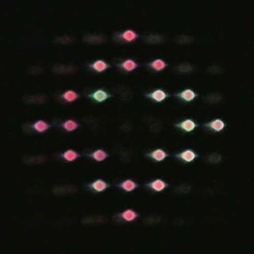
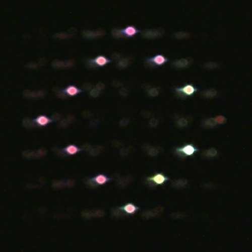
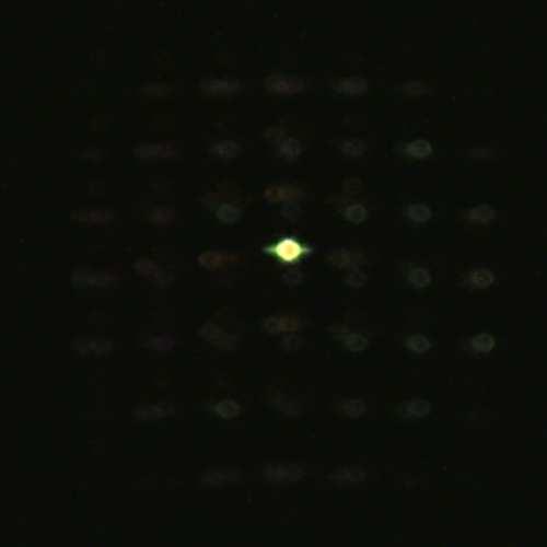

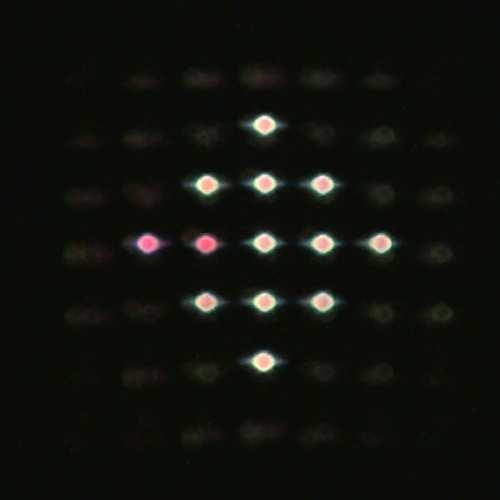


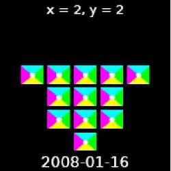
6 To appear in the ACM SIGGRAPH conference proceedings Figure 12: Design III as seen from top with top lid removed. left view center view right view light source moves outwards light source moves from bottom to top pattern Figure 14: 6D experiment and result (Design IV). Top: fully assembled prototype in mostly diffuse room illumination. The image resembles the pattern from Figure 15. Center row: changing observer direction induces a green to magenta color shift; horizontal light movement empties the patterns inside. Bottom row: vertical light movement induces different patterns. For light movements, we employed focal blur to visualize the effect better. observations Figure 13: Design III display result: a 4D projective display, as depicted in Figure 12, projects out different letters in the pattern to the left dependent on the incident light direction. Illuminating the corresponding directions in sequence projects the letters as spatial light distribution, as we have observed on a white receiver surface in the pictures on the right. the distance between (B) and (D), and choose the distances (B)-(D) and (D)-(E) to be the same. This allows for the use of the same lenslet arrays with focal length 10.5 mm as used in the prototype of Design 2. In plane (D), the arrays are again arranged in a backto-back configuration to double its focal length. The reuse of the same lenslet arrays in all four places lowers manufacturing costs. Choosing the distance between (A) and (B) to be 50 mm, we can use off-the-shelf coated plano-convex lenses from Edmund Optics Inc. with 50 mm focal length, and 25 mm diameter in plane (A) and 30 mm diameter in plane (B), respectively. Figure 15: 6D pattern for Design IV. The display shows simple diamond shapes for varying incident directions (left), and adds an angular color modulation, so that they appear magenta when seen from the right, white when seen from the center, and green when seen from the left. This yields the 6D pattern in the center, with a single pixel zoom-in on the right. In order to demonstrate the 4D design with angular variation, we put a pattern consisting of digits and letters in plane (D) (see Figure 13), and illuminated the prototype with a distant spot light. The output distribution is made visible by projection onto a diffuser screen which is not directly illuminated by the spot light. We translate the light source, that is, we change the angle of incidence, following the sequence indicated by the small arrows in Figure 13. The result is a time sequence of well readable letters projected onto the screen. In the corners ( 3 and 7 ) some vignetting as well as some distortion is noticeable. This could be removed if the field lens would be enlarged to equally cover all meso-pixels in plane (B). sign IV). Every macro-pixel independently produces some output distribution depending on the incident direction. Combined, the display project out different 4D light fields depending on the incident illumination. 5.4 We created a 6D pattern (see Figure 15) of simple illuminationdependent shapes which grow when the illumination is moved downwards, and appear increasingly hollow when illuminated from the sides. In each output pixel, and for each incident direction we further encode some color variation that depends on the viewing angle. For the sake of simplicity we chose the variation in color to be the same for every macro-pixel. The design does allow for a free configuration though. The results in Figure13 share some similarity with the patterns produced by the Design 2 in Figure 10. Design 2 implements an angular-to-spatial reflectance field R(ωin, xout ) where every output pixel individually depends on the incident light direction. Design III, on the other hand implements an angular-to-angular reflectance field R(ωin, ωout ). Each letter is projected out by a different meso-pixel. Therefore, the letters are continuous and not composed of sub-pixels. 5.3 Results for Design IV In order to produce the results in Figure 14 we surrounded the device by dark cloth and then illuminated and observed the display from distance. In the top image of Figure 14 one actually sees the integration of the patterns produced by the diffuse illumination in the room. At this resolution the structure of the meso-pixels is still Design IV Combining 7 7 macro-pixels of Design III we built a prototype for a 6D display implementing R(ωin, xout, ωout ) (Figure 14, De- 6
7 visible. In the two bottom lines, the device is again illuminated with a hand-held light bulb. The camera is slightly out of focus which makes the light transmitted by the individual meso-pixels more visible. As the camera is moved from left to right the color shift in each pixel can be observed. Moving the light source produces the intended shapes. Since the observer is not sufficiently distant to the display, we observe not only the white, but also red and green colored light rays, in the pictures for the center view. 6 Implementation details In the previous sections, we have introduced the optical design for our prototypes. Now, we will discuss how to generate the patterns from a reflectance field structure for the 4D case. For our analysis, as well as for the ray diagrams that we have previously shown, we will apply the assumption of paraxial optics, i.e. we assume that the angles of all light rays in our optical system to the optical axes of the lenses within are sufficiently small. In paraxial optics the change of direction and position of each ray due to a lens can be easily modeled with matrix methods [Gerrard and Burch 1975]. The encoding procedure for the pattern is as follows: for each pixel position (p x, p y) in the pattern determine the index (l x, l y) of the lenslet above the pixel determine the pixel position (s x, s y) relative to the optical axis of the lenslet simulate refraction at the lenslet in this pixel for a ray perpendicular to the pattern plane through (s x, s y), obtaining a ray in direction (θ, φ) color the pixel at (p x, p y) proportional to R(lx,ly,θ,φ), where cos κ κ is the angle of the refracted ray to the glass surface normal. This factor compensates for less light falling into the lenslet under flat angles. Finally, we tonemap the pattern by scaling its intensity linearly to a comfortable brightness and performing a gamma and blacklevel correction for the output device. We have tested printers based on laser, ink jet and solid ink technology, and achieved best results with an ink jet printer, putting two sheets back to back for increased contrast. The pattern used in the demonstrator of Design I in Figure 1 has been computed from a captured reflectance field. It has been recorded with indirect, extended illumination from the entire hemisphere around the object using a setup inspired by [Fuchs et al. 2007]. The display however can only render a smaller range of incident angles. In order to produce a more interesting experience of moving highlights at the top, we have virtually rotated the incident light by 45 degrees during the calculation of the patterns. In principle, one can also re-parameterize the reflectance field along the angular dimension in order to emphasize or suppress the angular dependence. 6.1 Pattern/Lens Registration The pattern and the lenses in our prototype have to be precisely aligned in order to modulate the correct light paths. For Design I, we have first measured the exact lens distance in the lenslet arrays to a higher precision than given by the manufacturer: we have printed patterns for a set of hypotheses and then chosen the distance which minimized the Moiré effects that occur when rotating the lens array on top of the pattern. For precise alignment of the final pattern, we have drilled holes into four lenses at the corners of the lenslet arrays under a microscope, and augmented the pattern by markers which show up below the holes. The patterns for the 6 5 lenslet arrays used in Design III and Design IV are manually cut and aligned. 7 Discussion 7.1 Limitations Our display designs come with some inherent limitations: For one, we only modulate the light that comes in from the back and project light out to the front side. Light integration is only performed and controlled from one hemisphere. Any light incident from the front hemisphere will limit the contrast to some extend. This is especially true for Designs I and II, which make use of a diffuser which inherently integrates the light from both sides. Another limitation is given by field of view of the front lenslet array or main lens. The displays currently use much less than the potential 180 degrees of illumination and observation. The same holds for the projection lenses in plane (E) of Design III which produce a rather narrow projection cone. As we use lenslet arrays without further angular blocking technology, wrapping can occur for rather shallow incident angles. In this case the light beam might cross over to the light path of a neighboring macro-pixel resulting in incorrect and distorted patterns. Since our display is passive, we can not emit more light from a single macro-pixel than the flux that hits the primary lens. Thus, we cannot display reflectance fields of complicated optical components that focus light from afar on a single pixel with full intensity. 7.2 Future Challenges There is a set of interesting extensions to the presented display prototypes. Most fundamental would likely be an extension to full 8D rendering, with arbitrary incident, non-distant 4D light fields. The design however is not obvious. As long as the light can be assumed distant and 2D parameterizable, we know that each macro lens is hit by the same incident light distribution, and therefore each pattern below the macro lens encodes arbitrarily distant global illumination effects (such as caustics or shadows). For a full 8D display that responds to a 4D incident light field, though, one would need to implement a coupling in the spatial domain. Some means of exchanging energy between different macro-pixels is required in order to faithfully reproduce global illumination effects such as caustics or subsurface scattering. This intrinsically requires a different design. Another interesting direction of future research might implement the controlled integration of the front hemisphere. The incident light could be reflected back, by a mirror for example. Separate modulation of viewing and illumination rays remains a challenge. In all the designs we presented, we manually cut out the patterns and aligned them with the optical components. This restricts the precision which we can build the prototypes with and keeps us from shrinking the single pixels, which would be required for higher resolutions. For industrial production, this should be less of an issue. A principle limit on the resolution of Design III and IV is given by the diffraction limit. Too small features in the modulation plane will widen the transmitted rays resulting in a blurred angular distribution. The diffraction limit is however less a problem for Design I as the resulting image is observed right after the modulation plane. The presented designs are all based around using lens systems in order to embed high dimensional information in planar surfaces. Holograms exploit variations in the phase of wave fronts; it 7
8 should be interesting to research possible extensions which incorporate holographic techniques for higher data densities and resolutions. Another technology that might influence this area of multidimensional displays is nanotechnology which can already produce surfaces with particularly designed reflection functions [Sun and Kim 2004; Min et al. 2007]. 7.3 Applications There is a large set of applications which the presented display designs might enable: Using Design I we can produce a relightable flattened copy of any 3D object which will automatically adapt to the incident illumination, providing a relightable object virtualization. This could be useful to present novel products, valuable artefacts, or for instruction manuals in a rather novel way. Manufacturing Design I at a larger scale one might cover a full window which automatically block or dims the direct sun light according to the time of day, as expressed by the sun position as it follows its arc on the sky. Since the modulation can be both in color and intensity one could also create mood lights. Inserting a high resolution LCD panel instead of the printed transparencies one can implement even a dynamic reflectance field display. In particular, one could control the transport of individual light rays and dispatch them into different directions. 7.4 Conclusions In this paper, we have presented design and prototypes for a set of different reflectance field displays. They are built using passive devices only, combining lenses and transparencies so as to modulate the outgoing light field depending on the incident light direction. Once built, the displays do not require sophisticated electronics, expensive computations or even electric current. The proposed designs make use of lenses to guide incident light beams to a particular location in the modulation plane. This design makes use of most of the light that hits the main lens or lens array. Compared to a possible design based on blockers it is inherently more light efficient. While the optical quality of some of the prototypes is currently limited, it can be expected to improve with industrial manufacture. With the presented designs we hope to inspire further exploration and developments of higher dimensional display technology. Acknowledgements We would like to thank our reviewers for all their suggestions and comments, John Barnwell, Douglas Lanman, and Boris Ajdin for help with building the actual prototypes, Conny Liegl and Boris Ajdin for help with the supplemental video, Ankit Mohan for fruitful discussions, and Jay Thornton and Joseph Katz for their support. This work has been partially funded by the DFG Emmy Noether fellowship (Le 1341/1-1), by the Max Planck Center for Visual Computing and Communication (BMBF-FKZ01IMC01), and by Mitsubishi Electric Research Labs. References DEBEVEC, P., HAWKINS, T., TCHOU, C., DUIKER, H.-P., SAROKIN, W., AND SAGAR, M Acquiring the reflectance field of a human face. In Proceedings of ACM SIG- GRAPH 2000, Computer Graphics Proceedings, Annual Conference Series, FUCHS, M., BLANZ, V., LENSCH, H. P. A., AND SEIDEL, H.-P Adaptive sampling of reflectance fields. ACM Transactions on Graphics (TOG) 26, 2 (June). GEORGIEV, T., ZHENG, K. C., CURLESS, B., SALESIN, D., NA- YAR, S., AND INTWALA, C Spatio-angular resolution trade-offs in integral photography. In Rendering Techniques 2006: Eurographics Symposium on Rendering, GERRARD, A., AND BURCH, J. M Introduction to Matrix Methods in Optics. John Wiley & Sons, New York - Chichester - Brisbane. ISAKSEN, A., MCMILLAN, L., AND GORTLER, S. J Dynamically reparameterized light fields. In Proceedings of ACM SIGGRAPH 2000, Computer Graphics Proceedings, Annual Conference Series, JAVIDI, B., AND OKANO, F. (ED.) Three-dimensional video and display: devices and systems. SPIE, Washington, USA. KOIKE, T., AND NAEMURA, T BRDF display. SIGGRAPH 2007 poster presentation. LEVOY, M., NG, R., ADAMS, A., FOOTER, M., AND HOROWITZ, M Light field microscopy. ACM Trans. Graph. (Proc. SIGGRAPH) 25, 3, LIPPMANN, G Epreuves reversibles donnant la sensation du relief. Journal of Physics 7, MATUSIK, W., AND PFISTER, H D TV: a scalable system for real-time acquisition, transmission, and autostereoscopic display of dynamic scenes. ACM Trans. Graph. (Proc. SIGGRAPH) 23, 3, MIN, C., WANG, P., JIAO, X., DENG, Y., AND MING, H Beam manipulating by metallic nano-optic lens containing nonlinear media. Opt. Express 15, 15, NAKAJIMA, S., NAKAMURA, K., MASAMUNE, K., SAKUMA, I., AND T., T. D Three-dimensional medical imaging display with computer-generated integral photography. Computerized Medical Imaging and Graphics 25, NAYAR, S. K., BELHUMEUR, P. N., AND BOULT, T. E Lighting sensitive display. ACM Trans. Graph. 23, 4, NG, R., LEVOY, M., BRÉDIF, M., DUVAL, G., HOROWITZ, M., AND HANRAHAN, P Light field photography with a handheld plenoptic camera. Stanford University Computer Scienece Tech Report. SCHARSTEIN, H., KROTZ-VOGEL, W., AND SCHARSTEIN, D Digital sundial. In US patent , German patent SUN, Z., AND KIM, H. K Refractive transmission of light and beam shaping with metallic nano-optic lenses. Appl. Phys. Lett. 85, 652. VEERARAGHAVAN, A., RASKAR, R., AGRAWAL, A., MOHAN, A., AND TUMBLIN, J Dappled photography: mask enhanced cameras for heterodyned light fields and coded aperture refocusing. ACM Trans. Graph. (Proc. SIGGRAPH) 26, 3, 69. ZIEGLER, R., BUCHELI, S., AHRENBERG, L., MAGNOR, M., AND GROSS, M A bidirectional light field - hologram transform. In Computer Graphics Forum (Proc. Eurographics), D. Cohen Or and P. Slavik, Eds., vol. 26,
Computational Cameras: Exploiting Spatial- Angular Temporal Tradeoffs in Photography
 Mitsubishi Electric Research Labs (MERL) Computational Cameras Computational Cameras: Exploiting Spatial- Angular Temporal Tradeoffs in Photography Amit Agrawal Mitsubishi Electric Research Labs (MERL)
Introduction to 3D Concepts
 PART I Introduction to 3D Concepts Chapter 1 Scene... 3 Chapter 2 Rendering: OpenGL (OGL) and Adobe Ray Tracer (ART)...19 1 CHAPTER 1 Scene s0010 1.1. The 3D Scene p0010 A typical 3D scene has several
Traditional Image Generation. Reflectance Fields. The Light Field. The Light Field. The Light Field. The Light Field
 Traditional Image Generation Course 10 Realistic Materials in Computer Graphics Surfaces + BRDFs Reflectance Fields USC Institute for Creative Technologies Volumetric scattering, density fields, phase
4. A bulb has a luminous flux of 2400 lm. What is the luminous intensity of the bulb?
 1. Match the physical quantities (first column) with the units (second column). 4. A bulb has a luminous flux of 2400 lm. What is the luminous intensity of the bulb? (π=3.) Luminous flux A. candela Radiant
Physical Optics. You can observe a lot just by watching. Yogi Berra ( )
") Physical Optics You can observe a lot just by watching. Yogi Berra (1925-2015) OBJECTIVES To observe some interference and diffraction phenomena with visible light. THEORY In a previous experiment you
Physical Optics You can observe a lot just by watching. Yogi Berra (1925-2015) OBJECTIVES To observe some interference and diffraction phenomena with visible light. THEORY In a previous experiment you
Today. Global illumination. Shading. Interactive applications. Rendering pipeline. Computergrafik. Shading Introduction Local shading models
 Computergrafik Matthias Zwicker Universität Bern Herbst 2009 Today Introduction Local shading models Light sources strategies Compute interaction of light with surfaces Requires simulation of physics Global
Natural Viewing 3D Display
 We will introduce a new category of Collaboration Projects, which will highlight DoCoMo s joint research activities with universities and other companies. DoCoMo carries out R&D to build up mobile communication,
Shading of a computer-generated hologram by zone plate modulation
 Shading of a computer-generated hologram by zone plate modulation Takayuki Kurihara * and Yasuhiro Takaki Institute of Engineering, Tokyo University of Agriculture and Technology, 2-24-16 Naka-cho, Koganei,Tokyo
specular diffuse reflection.
 Lesson 8 Light and Optics The Nature of Light Properties of Light: Reflection Refraction Interference Diffraction Polarization Dispersion and Prisms Total Internal Reflection Huygens s Principle The Nature
Integrated three-dimensional reconstruction using reflectance fields
 www.ijcsi.org 32 Integrated three-dimensional reconstruction using reflectance fields Maria-Luisa Rosas 1 and Miguel-Octavio Arias 2 1,2 Computer Science Department, National Institute of Astrophysics,
CSE 167: Introduction to Computer Graphics Lecture #6: Lights. Jürgen P. Schulze, Ph.D. University of California, San Diego Fall Quarter 2016
 CSE 167: Introduction to Computer Graphics Lecture #6: Lights Jürgen P. Schulze, Ph.D. University of California, San Diego Fall Quarter 2016 Announcements Thursday in class: midterm #1 Closed book Material
Coding and Modulation in Cameras
 Mitsubishi Electric Research Laboratories Raskar 2007 Coding and Modulation in Cameras Ramesh Raskar with Ashok Veeraraghavan, Amit Agrawal, Jack Tumblin, Ankit Mohan Mitsubishi Electric Research Labs
Title: The Future of Photography is Computational Photography. Subtitle: 100 years after invention, Integral Photography becomes feasible
 Title: The Future of Photography is Computational Photography Subtitle: 100 years after invention, Integral Photography becomes feasible Adobe customers are creative and demanding. They expect to use our
Michelson Interferometer
 Michelson Interferometer The Michelson interferometer uses the interference of two reflected waves The third, beamsplitting, mirror is partially reflecting ( half silvered, except it s a thin Aluminum
Overview of Active Vision Techniques
 SIGGRAPH 99 Course on 3D Photography Overview of Active Vision Techniques Brian Curless University of Washington Overview Introduction Active vision techniques Imaging radar Triangulation Moire Active
Computational Photography
 Computational Photography Matthias Zwicker University of Bern Fall 2010 Today Light fields Introduction Light fields Signal processing analysis Light field cameras Application Introduction Pinhole camera
2/26/2016. Chapter 23 Ray Optics. Chapter 23 Preview. Chapter 23 Preview
 Chapter 23 Ray Optics Chapter Goal: To understand and apply the ray model of light. Slide 23-2 Chapter 23 Preview Slide 23-3 Chapter 23 Preview Slide 23-4 1 Chapter 23 Preview Slide 23-5 Chapter 23 Preview
ENGR142 PHYS 115 Geometrical Optics and Lenses
 ENGR142 PHYS 115 Geometrical Optics and Lenses Part A: Rays of Light Part B: Lenses: Objects, Images, Aberration References Pre-lab reading Serway and Jewett, Chapters 35 and 36. Introduction Optics play
4. Refraction. glass, air, Perspex and water.
 Mr. C. Grima 11 1. Rays and Beams A ray of light is a narrow beam of parallel light, which can be represented by a line with an arrow on it, in diagrams. A group of rays makes up a beam of light. In laboratory
CMSC427 Shading Intro. Credit: slides from Dr. Zwicker
 CMSC427 Shading Intro Credit: slides from Dr. Zwicker 2 Today Shading Introduction Radiometry & BRDFs Local shading models Light sources Shading strategies Shading Compute interaction of light with surfaces
All forms of EM waves travel at the speed of light in a vacuum = 3.00 x 10 8 m/s This speed is constant in air as well
 Pre AP Physics Light & Optics Chapters 14-16 Light is an electromagnetic wave Electromagnetic waves: Oscillating electric and magnetic fields that are perpendicular to the direction the wave moves Difference
Understanding Variability
 Understanding Variability Why so different? Light and Optics Pinhole camera model Perspective projection Thin lens model Fundamental equation Distortion: spherical & chromatic aberration, radial distortion
Chapter 38. Diffraction Patterns and Polarization
 Chapter 38 Diffraction Patterns and Polarization Diffraction Light of wavelength comparable to or larger than the width of a slit spreads out in all forward directions upon passing through the slit This
Multi-projector-type immersive light field display
 Multi-projector-type immersive light field display Qing Zhong ( é) 1, Beishi Chen (í ì) 1, Haifeng Li (Ó ô) 1, Xu Liu ( Ê) 1, Jun Xia ( ) 2, Baoping Wang ( ) 2, and Haisong Xu (Å Ø) 1 1 State Key Laboratory
Extended Fractional View Integral Photography Using Slanted Orthogonal Lenticular Lenses
 Proceedings of the 2 nd World Congress on Electrical Engineering and Computer Systems and Science (EECSS'16) Budapest, Hungary August 16 17, 2016 Paper No. MHCI 112 DOI: 10.11159/mhci16.112 Extended Fractional
Announcements. Light. Properties of light. Light. Project status reports on Wednesday. Readings. Today. Readings Szeliski, 2.2, 2.3.
 Announcements Project status reports on Wednesday prepare 5 minute ppt presentation should contain: problem statement (1 slide) description of approach (1 slide) some images (1 slide) current status +
Chapter 26 Geometrical Optics
 Chapter 26 Geometrical Optics 26.1 The Reflection of Light 26.2 Forming Images With a Plane Mirror 26.3 Spherical Mirrors 26.4 Ray Tracing and the Mirror Equation 26.5 The Refraction of Light 26.6 Ray
AP* Optics Free Response Questions
 AP* Optics Free Response Questions 1978 Q5 MIRRORS An object 6 centimeters high is placed 30 centimeters from a concave mirror of focal length 10 centimeters as shown above. (a) On the diagram above, locate
Chapter 24. Wave Optics
 Chapter 24 Wave Optics Wave Optics The wave nature of light is needed to explain various phenomena Interference Diffraction Polarization The particle nature of light was the basis for ray (geometric) optics
Chapter 32 Light: Reflection and Refraction. Copyright 2009 Pearson Education, Inc.
 Chapter 32 Light: Reflection and Refraction Units of Chapter 32 The Ray Model of Light Reflection; Image Formation by a Plane Mirror Formation of Images by Spherical Mirrors Index of Refraction Refraction:
CSE 167: Lecture #7: Color and Shading. Jürgen P. Schulze, Ph.D. University of California, San Diego Fall Quarter 2011
 CSE 167: Introduction to Computer Graphics Lecture #7: Color and Shading Jürgen P. Schulze, Ph.D. University of California, San Diego Fall Quarter 2011 Announcements Homework project #3 due this Friday,
Conceptual Physics 11 th Edition
 Conceptual Physics 11 th Edition Chapter 28: REFLECTION & REFRACTION This lecture will help you understand: Reflection Principle of Least Time Law of Reflection Refraction Cause of Refraction Dispersion
PHYSICS. Chapter 34 Lecture FOR SCIENTISTS AND ENGINEERS A STRATEGIC APPROACH 4/E RANDALL D. KNIGHT
 PHYSICS FOR SCIENTISTS AND ENGINEERS A STRATEGIC APPROACH 4/E Chapter 34 Lecture RANDALL D. KNIGHT Chapter 34 Ray Optics IN THIS CHAPTER, you will learn about and apply the ray model of light Slide 34-2
Midterm Exam CS 184: Foundations of Computer Graphics page 1 of 11
 Midterm Exam CS 184: Foundations of Computer Graphics page 1 of 11 Student Name: Class Account Username: Instructions: Read them carefully! The exam begins at 2:40pm and ends at 4:00pm. You must turn your
An Intuitive Explanation of Fourier Theory
 An Intuitive Explanation of Fourier Theory Steven Lehar slehar@cns.bu.edu Fourier theory is pretty complicated mathematically. But there are some beautifully simple holistic concepts behind Fourier theory
Acquiring 4D Light Fields of Self-Luminous Light Sources Using Programmable Filter
 Acquiring 4D Light Fields of Self-Luminous Light Sources Using Programmable Filter Motohiro Nakamura 1, Takahiro Okabe 1, and Hendrik P. A. Lensch 2 1 Kyushu Institute of Technology 2 Tübingen University
Radiance Photography. Todor Georgiev Adobe Systems. Andrew Lumsdaine Indiana University
 Radiance Photography Todor Georgiev Adobe Systems Andrew Lumsdaine Indiana University Course Goals Overview of radiance (aka lightfield) photography Mathematical treatment of theory and computation Hands
25 The vibration spiral
 25 The vibration spiral Contents 25.1 The vibration spiral 25.1.1 Zone Plates............................... 10 25.1.2 Circular obstacle and Poisson spot.................. 13 Keywords: Fresnel Diffraction,
PHYSICS. Chapter 33 Lecture FOR SCIENTISTS AND ENGINEERS A STRATEGIC APPROACH 4/E RANDALL D. KNIGHT
 PHYSICS FOR SCIENTISTS AND ENGINEERS A STRATEGIC APPROACH 4/E Chapter 33 Lecture RANDALL D. KNIGHT Chapter 33 Wave Optics IN THIS CHAPTER, you will learn about and apply the wave model of light. Slide
Chapter 15. Light Waves
 Chapter 15 Light Waves Chapter 15 is finished, but is not in camera-ready format. All diagrams are missing, but here are some excerpts from the text with omissions indicated by... After 15.1, read 15.2
Color and Shading. Color. Shapiro and Stockman, Chapter 6. Color and Machine Vision. Color and Perception
 Color and Shading Color Shapiro and Stockman, Chapter 6 Color is an important factor for for human perception for object and material identification, even time of day. Color perception depends upon both
Chapter 12 Notes: Optics
 Chapter 12 Notes: Optics How can the paths traveled by light rays be rearranged in order to form images? In this chapter we will consider just one form of electromagnetic wave: visible light. We will be
Wave Optics. April 11, 2014 Chapter 34 1
 Wave Optics April 11, 2014 Chapter 34 1 Announcements! Exam tomorrow! We/Thu: Relativity! Last week: Review of entire course, no exam! Final exam Wednesday, April 30, 8-10 PM Location: WH B115 (Wells Hall)
dq dt I = Irradiance or Light Intensity is Flux Φ per area A (W/m 2 ) Φ =
 Φ =") Radiometry (From Intro to Optics, Pedrotti -4) Radiometry is measurement of Emag radiation (light) Consider a small spherical source Total energy radiating from the body over some time is Q total Radiant
Radiometry (From Intro to Optics, Pedrotti -4) Radiometry is measurement of Emag radiation (light) Consider a small spherical source Total energy radiating from the body over some time is Q total Radiant
Devices displaying 3D image. RNDr. Róbert Bohdal, PhD.
 Devices displaying 3D image RNDr. Róbert Bohdal, PhD. 1 Types of devices displaying 3D image Stereoscopic Re-imaging Volumetric Autostereoscopic Holograms mounted displays, optical head-worn displays Pseudo
Today. Global illumination. Shading. Interactive applications. Rendering pipeline. Computergrafik. Shading Introduction Local shading models
 Computergrafik Thomas Buchberger, Matthias Zwicker Universität Bern Herbst 2008 Today Introduction Local shading models Light sources strategies Compute interaction of light with surfaces Requires simulation
Image-based BRDF Representation
 JAMSI, 11 (2015), No. 2 47 Image-based BRDF Representation A. MIHÁLIK AND R. ĎURIKOVIČ Abstract: To acquire a certain level of photorealism in computer graphics, it is necessary to analyze, how the materials
CSE 167: Introduction to Computer Graphics Lecture #6: Colors. Jürgen P. Schulze, Ph.D. University of California, San Diego Fall Quarter 2013
 CSE 167: Introduction to Computer Graphics Lecture #6: Colors Jürgen P. Schulze, Ph.D. University of California, San Diego Fall Quarter 2013 Announcements Homework project #3 due this Friday, October 18
Physics 1C, Summer 2011 (Session 1) Practice Midterm 2 (50+4 points) Solutions
 Practice Midterm 2 (50+4 points) Solutions") Physics 1C, Summer 2011 (Session 1) Practice Midterm 2 (50+4 points) s Problem 1 (5x2 = 10 points) Label the following statements as True or False, with a one- or two-sentence explanation for why you chose
Physics 1C, Summer 2011 (Session 1) Practice Midterm 2 (50+4 points) s Problem 1 (5x2 = 10 points) Label the following statements as True or False, with a one- or two-sentence explanation for why you chose
AP Physics Problems -- Waves and Light
 AP Physics Problems -- Waves and Light 1. 1975-4 (Physical Optics) a. Light of a single wavelength is incident on a single slit of width w. (w is a few wavelengths.) Sketch a graph of the intensity as
Intermediate Physics PHYS102
 Intermediate Physics PHYS102 Dr Richard H. Cyburt Assistant Professor of Physics My office: 402c in the Science Building My phone: (304) 384-6006 My email: rcyburt@concord.edu My webpage: www.concord.edu/rcyburt
Light. Properties of light. What is light? Today What is light? How do we measure it? How does light propagate? How does light interact with matter?
 Light Properties of light Today What is light? How do we measure it? How does light propagate? How does light interact with matter? by Ted Adelson Readings Andrew Glassner, Principles of Digital Image
Engineered Diffusers Intensity vs Irradiance
 Engineered Diffusers Intensity vs Irradiance Engineered Diffusers are specified by their divergence angle and intensity profile. The divergence angle usually is given as the width of the intensity distribution
Diffraction. Single-slit diffraction. Diffraction by a circular aperture. Chapter 38. In the forward direction, the intensity is maximal.
 Diffraction Chapter 38 Huygens construction may be used to find the wave observed on the downstream side of an aperture of any shape. Diffraction The interference pattern encodes the shape as a Fourier
Computer Vision. The image formation process
 Computer Vision The image formation process Filippo Bergamasco (filippo.bergamasco@unive.it) http://www.dais.unive.it/~bergamasco DAIS, Ca Foscari University of Venice Academic year 2016/2017 The image
Textbook Reference: Physics (Wilson, Buffa, Lou): Chapter 24
: Chapter 24") AP Physics-B Physical Optics Introduction: We have seen that the reflection and refraction of light can be understood in terms of both rays and wave fronts of light. Light rays are quite compatible with
AP Physics-B Physical Optics Introduction: We have seen that the reflection and refraction of light can be understood in terms of both rays and wave fronts of light. Light rays are quite compatible with
Next Generation CAT System
 Next Generation CAT System Jaewon Kim MIT Media Lab Advisor: Ramesh Raskar Associate Professor of Media Arts & Sciences MIT Media Lab Reader: V. Michael Bove Principal Research Scientist of Media Arts
Lighting & 3D Graphics. Images from 3D Creative Magazine
 Lighting & 3D Graphics Images from 3D Creative Magazine Contents Introduction Definitions 3D Lighting Basics 3D Light Sources Lighting Controls & Effects Brightness & Colour Shadows Hotspot And Falloff
Focal stacks and lightfields
 Focal stacks and lightfields http://graphics.cs.cmu.edu/courses/15-463 15-463, 15-663, 15-862 Computational Photography Fall 2018, Lecture 11 Course announcements Homework 3 is out. - Due October 12 th.
Augmenting Reality with Projected Interactive Displays
 Augmenting Reality with Projected Interactive Displays Claudio Pinhanez IBM T.J. Watson Research Center, P.O. Box 218 Yorktown Heights, N.Y. 10598, USA Abstract. This paper examines a steerable projection
(Refer Slide Time 00:17) Welcome to the course on Digital Image Processing. (Refer Slide Time 00:22)
 Welcome to the course on Digital Image Processing. (Refer Slide Time 00:22)") Digital Image Processing Prof. P. K. Biswas Department of Electronics and Electrical Communications Engineering Indian Institute of Technology, Kharagpur Module Number 01 Lecture Number 02 Application
Digital Image Processing Prof. P. K. Biswas Department of Electronics and Electrical Communications Engineering Indian Institute of Technology, Kharagpur Module Number 01 Lecture Number 02 Application
Computer Graphics. Illumination and Shading
 () Illumination and Shading Dr. Ayman Eldeib Lighting So given a 3-D triangle and a 3-D viewpoint, we can set the right pixels But what color should those pixels be? If we re attempting to create a realistic
OPTICS MIRRORS AND LENSES
 Downloaded from OPTICS MIRRORS AND LENSES 1. An object AB is kept in front of a concave mirror as shown in the figure. (i)complete the ray diagram showing the image formation of the object. (ii) How will
CS6670: Computer Vision
 CS6670: Computer Vision Noah Snavely Lecture 21: Light, reflectance and photometric stereo Announcements Final projects Midterm reports due November 24 (next Tuesday) by 11:59pm (upload to CMS) State the
10.5 Polarization of Light
 10.5 Polarization of Light Electromagnetic waves have electric and magnetic fields that are perpendicular to each other and to the direction of propagation. These fields can take many different directions
Application note Fast focusing for machine vision applications With Optotune s focus tunable lenses EL C and EL-6-18
 Application note Fast focusing for machine vision applications With Optotune s focus tunable lenses EL-10-30-C and EL-6-18 Page 1 of 11 Introduction Flexible and fast focusing solutions with electrically
Draw Guide. Chapter 7 Working with 3D Objects
 Draw Guide Chapter 7 Working with 3D Objects Copyright This document is Copyright 2011 2014 by the LibreOffice Documentation Team. Contributors are listed below. You may distribute or modify it under the
4) Finish the spline here. To complete the spline, double click the last point or select the spline tool again.
 Finish the spline here. To complete the spline, double click the last point or select the spline tool again.") 1) Select the line tool 3) Move the cursor along the X direction (be careful to stay on the X axis alignment so that the line is perpendicular) and click for the second point of the line. Type 0.5 for
1) Select the line tool 3) Move the cursor along the X direction (be careful to stay on the X axis alignment so that the line is perpendicular) and click for the second point of the line. Type 0.5 for
Available online at ScienceDirect. Energy Procedia 69 (2015 )
") Available online at www.sciencedirect.com ScienceDirect Energy Procedia 69 (2015 ) 1885 1894 International Conference on Concentrating Solar Power and Chemical Energy Systems, SolarPACES 2014 Heliostat
Available online at www.sciencedirect.com ScienceDirect Energy Procedia 69 (2015 ) 1885 1894 International Conference on Concentrating Solar Power and Chemical Energy Systems, SolarPACES 2014 Heliostat
Topic 9: Lighting & Reflection models. Lighting & reflection The Phong reflection model diffuse component ambient component specular component
 Topic 9: Lighting & Reflection models Lighting & reflection The Phong reflection model diffuse component ambient component specular component Spot the differences Terminology Illumination The transport
Reflections. I feel pretty, oh so pretty
 Reflections I feel pretty, oh so pretty Objectives By the end of the lesson, you should be able to: Draw an accurate reflective angle Determine the focal length of a spherical mirror Light Review Light
Real-time Integral Photography Holographic Pyramid using a Game Engine
 Real-time Integral Photography Holographic Pyramid using a Game Engine Shohei Anraku, Toshiaki Yamanouchi and Kazuhisa Yanaka Kanagawa Institute of Technology, 1030 Shimo-ogino, Atsugi-shi, Kanagawa-ken,
A Frequency Analysis of Light Transport
 A Frequency Analysis of Light Transport Frédo Durand MIT CSAIL With Nicolas Holzschuch, Cyril Soler, Eric Chan & Francois Sillion Artis Gravir/Imag-Inria & MIT CSAIL Our research 3D rendering Light transport
Simulating Gloss of Curved Paper by Using the Point Spread Function of Specular Reflection
 Simulating Gloss of Curved Paper by Using the Point Spread Function of Specular Reflection Norimichi Tsumura*, Kaori Baba*, and Shinichi Inoue** *Department of Information and Image Sciences, Chiba University,
Global Illumination. CSCI 420 Computer Graphics Lecture 18. BRDFs Raytracing and Radiosity Subsurface Scattering Photon Mapping [Ch
 CSCI 420 Computer Graphics Lecture 18 Global Illumination Jernej Barbic University of Southern California BRDFs Raytracing and Radiosity Subsurface Scattering Photon Mapping [Ch. 13.4-13.5] 1 Global Illumination
PHYS:1200 LECTURE 32 LIGHT AND OPTICS (4)
") 1 PHYS:1200 LECTURE 32 LIGHT AND OPTICS (4) The first three lectures in this unit dealt with what is for called geometric optics. Geometric optics, treats light as a collection of rays that travel in straight
1 PHYS:1200 LECTURE 32 LIGHT AND OPTICS (4) The first three lectures in this unit dealt with what is for called geometric optics. Geometric optics, treats light as a collection of rays that travel in straight
Soft shadows. Steve Marschner Cornell University CS 569 Spring 2008, 21 February
 Soft shadows Steve Marschner Cornell University CS 569 Spring 2008, 21 February Soft shadows are what we normally see in the real world. If you are near a bare halogen bulb, a stage spotlight, or other
Global Illumination CS334. Daniel G. Aliaga Department of Computer Science Purdue University
 Global Illumination CS334 Daniel G. Aliaga Department of Computer Science Purdue University Recall: Lighting and Shading Light sources Point light Models an omnidirectional light source (e.g., a bulb)
Chapter 36. Diffraction. Dr. Armen Kocharian
 Chapter 36 Diffraction Dr. Armen Kocharian Diffraction Light of wavelength comparable to or larger than the width of a slit spreads out in all forward directions upon passing through the slit This phenomena
The branch of physics which studies light
 Mr.V The branch of physics which studies light Geometric model XVI century by W Snell Wave Model XIX century by JC Maxwell Photon Model XX century by Planck, Einstein Models of Light Basic Concept Laws
Chapter 37. Interference of Light Waves
 Chapter 37 Interference of Light Waves Wave Optics Wave optics is a study concerned with phenomena that cannot be adequately explained by geometric (ray) optics These phenomena include: Interference Diffraction
Ray Optics I. Last time, finished EM theory Looked at complex boundary problems TIR: Snell s law complex Metal mirrors: index complex
 Phys 531 Lecture 8 20 September 2005 Ray Optics I Last time, finished EM theory Looked at complex boundary problems TIR: Snell s law complex Metal mirrors: index complex Today shift gears, start applying
S U N G - E U I YO O N, K A I S T R E N D E R I N G F R E E LY A VA I L A B L E O N T H E I N T E R N E T
 S U N G - E U I YO O N, K A I S T R E N D E R I N G F R E E LY A VA I L A B L E O N T H E I N T E R N E T Copyright 2018 Sung-eui Yoon, KAIST freely available on the internet http://sglab.kaist.ac.kr/~sungeui/render
Rodenstock Products Photo Optics / Digital Imaging
 Go to Rogonar Rogonar-S Rodagon Apo-Rodagon-N Rodagon-WA Apo-Rodagon-D Accessories: Modular-Focus Lenses for Enlarging, CCD Photos and Video To reproduce a photograph as a picture on paper requires two
Spectrographs. C. A. Griffith, Class Notes, PTYS 521, 2016 Not for distribution.
 Spectrographs C A Griffith, Class Notes, PTYS 521, 2016 Not for distribution 1 Spectrographs and their characteristics A spectrograph is an instrument that disperses light into a frequency spectrum, which
Optics Test Science What are some devices that you use in everyday life that require optics?
 Optics Test Science 8 Introduction to Optics 1. What are some devices that you use in everyday life that require optics? Light Energy and Its Sources 308-8 identify and describe properties of visible light
Chapter 36. Image Formation
 Chapter 36 Image Formation Apr 22, 2012 Light from distant things We learn about a distant thing from the light it generates or redirects. The lenses in our eyes create images of objects our brains can
SAMPLING AND NOISE. Increasing the number of samples per pixel gives an anti-aliased image which better represents the actual scene.
 SAMPLING AND NOISE When generating an image, Mantra must determine a color value for each pixel by examining the scene behind the image plane. Mantra achieves this by sending out a number of rays from
Global Illumination. Global Illumination. Direct Illumination vs. Global Illumination. Indirect Illumination. Soft Shadows.
 CSCI 420 Computer Graphics Lecture 18 Global Illumination Jernej Barbic University of Southern California BRDFs Raytracing and Radiosity Subsurface Scattering Photon Mapping [Angel Ch. 11] 1 Global Illumination
x ~ Hemispheric Lighting
 Irradiance and Incoming Radiance Imagine a sensor which is a small, flat plane centered at a point ~ x in space and oriented so that its normal points in the direction n. This sensor can compute the total
Light Field Occlusion Removal
 Light Field Occlusion Removal Shannon Kao Stanford University kaos@stanford.edu Figure 1: Occlusion removal pipeline. The input image (left) is part of a focal stack representing a light field. Each image
Chapter 37. Wave Optics
 Chapter 37 Wave Optics Wave Optics Wave optics is a study concerned with phenomena that cannot be adequately explained by geometric (ray) optics. Sometimes called physical optics These phenomena include:
Chapter 24. Wave Optics. Wave Optics. The wave nature of light is needed to explain various phenomena
 Chapter 24 Wave Optics Wave Optics The wave nature of light is needed to explain various phenomena Interference Diffraction Polarization The particle nature of light was the basis for ray (geometric) optics
Introduction to Computer Vision. Introduction CMPSCI 591A/691A CMPSCI 570/670. Image Formation
 Introduction CMPSCI 591A/691A CMPSCI 570/670 Image Formation Lecture Outline Light and Optics Pinhole camera model Perspective projection Thin lens model Fundamental equation Distortion: spherical & chromatic
OPSE FINAL EXAM Fall CLOSED BOOK. Two pages (front/back of both pages) of equations are allowed.
 of equations are allowed.") CLOSED BOOK. Two pages (front/back of both pages) of equations are allowed. YOU MUST SHOW YOUR WORK. ANSWERS THAT ARE NOT JUSTIFIED WILL BE GIVEN ZERO CREDIT. ALL NUMERICAL ANSERS MUST HAVE UNITS INDICATED.
CLOSED BOOK. Two pages (front/back of both pages) of equations are allowed. YOU MUST SHOW YOUR WORK. ANSWERS THAT ARE NOT JUSTIFIED WILL BE GIVEN ZERO CREDIT. ALL NUMERICAL ANSERS MUST HAVE UNITS INDICATED.
3B SCIENTIFIC PHYSICS
 3B SCIENTIFIC PHYSICS Instruction sheet 06/18 ALF Laser Optics Demonstration Set Laser Optics Supplement Set Page 1 2 3 3 3 4 4 4 5 5 5 6 6 6 7 7 7 8 8 8 9 9 9 10 10 10 11 11 11 12 12 12 13 13 13 14 14
Lecture 7 Notes: 07 / 11. Reflection and refraction
 Lecture 7 Notes: 07 / 11 Reflection and refraction When an electromagnetic wave, such as light, encounters the surface of a medium, some of it is reflected off the surface, while some crosses the boundary
What is it? How does it work? How do we use it?
 What is it? How does it work? How do we use it? Dual Nature http://www.youtube.com/watch?v=dfpeprq7ogc o Electromagnetic Waves display wave behavior o Created by oscillating electric and magnetic fields
25-1 Interference from Two Sources
 25-1 Interference from Two Sources In this chapter, our focus will be on the wave behavior of light, and on how two or more light waves interfere. However, the same concepts apply to sound waves, and other
Lecture 17: Recursive Ray Tracing. Where is the way where light dwelleth? Job 38:19
 Lecture 17: Recursive Ray Tracing Where is the way where light dwelleth? Job 38:19 1. Raster Graphics Typical graphics terminals today are raster displays. A raster display renders a picture scan line