VERO UK TRAINING MATERIAL
|
|
|
- Gilbert Horton
- 5 years ago
- Views:
Transcription


1 VERO UK TRAINING MATERIAL Draft Analysis
2 VISI Modelling Draft Analysis INTRODUCTION Pre-requisite It is important that before you attempt this VISI-Analysis training example; you must have completed and fully understood the previous VISI-Design and VISI-Modelling and VISI- Surface Modelling examples. During this exercise, it is assumed that the user has a basic knowledge of the VISI-Series software. Object The following example will highlight some of the required techniques to fully utilise the dedicated analysis functions within VISI-Modelling. Vcamtech Co., Ltd 1

3 VISI Modelling Draft Analysis Start by opening the workfile: - File > Open Select the file named Front Cover.wkf The model should look as below: - The GREEN model will reside on the Part 1 layer. Part 1 is to be used as the first revision of a plastic component. There will be a second ORANGE model that resides on the Part 2 layer. The second model represents a second revision of the same component. We will use the VISI-Comparison module to check for the model differences between Part 1 and Part 2. Switch ON both the Part 1 and Part 2 layer to show both models together. Analysis > Compare Select the first body - Select PART 1 ( the original GREEN solid model ) Select the body to compare - Select PART 2 (the second ORANGE solid model ) NOTE : The comparison tolerance value can be changed from inside the compare control panel. Vcamtech Co., Ltd 2


4 VISI Modelling Draft Analysis A new interface will be displayed (shown below) There are two methods of display for the new comparison module. The Fast method allows the user to show all of the faces that are different between the two models to within a single tolerance. The Accurate method allows the user to identify all of the faces that are different between the two models and colour them with up to 5 different bands of colour. When the Fast method is selected, 4 modes of operation are possible: - Comparison detection method None The two models are shaded using the two colours. No differences are detected. The user can move the transparency percentage slider to observe the differences. Vcamtech Co., Ltd 3

.")
5 VISI Modelling Draft Analysis Only common faces Faces that are identical (to within the set tolerance) will be coloured in the common colour. Other faces will be coloured first or second colour as appropriate. Partially common faces The models are coloured the same as Only common faces above except, faces that have both identical and different areas will be split coloured (i.e. Common colour and first or second colour as appropriate). External Internal zones This mode will activate the internal and external colour selection icons (and disable the basic first and second colour icons). The models will be coloured with the common colour and the areas that are different will be coloured using the Internal or External colour depending upon whether the situation is metal on or metal missing Apply Update the display Set the detection method here The colours for the first and second models can be set here The comparison tolerance is set here. Differences less than this will be shown as common Select the Transparency option to activate a slider bar. Moving the slider bar will dynamically show both models If Show common zones is set, the complete model will be displayed. If this option is switched off, only the different faces will be displayed Moving the transparency slider bar will display both sets of faces on either model Vcamtech Co., Ltd 4

6 VISI Modelling Draft Analysis If you switch OFF the show tick box in Common zones and update the graphics, it is very quick and easy to see the design changes for the new revision of the solid model. The design changes displayed without the common zones visible Now we know what the design changes are, CANCEL out of the comparison module by pressing the X. We will continue to use the rest of the Analysis tools and work on Part 2 (ORANGE model). Switch ON only the Part 2 layer and also make it the current working layer (green arrow). Analysis > Draft Analysis Select the model to analyse Select the ORANGE solid Select the plane normal Select the Z axis (confirm using RHM) After selecting the plane normal a display panel will be presented to the left hand side. Using this control panel it is possible to manipulate the draft angle values Vcamtech Co., Ltd 5

7 VISI Modelling Draft Analysis Load default Parameters This will allow you to load the default angle range values previously defined 2. Save Default Parameters After setting the default angle range values, it is possible to save the values and recall them for another model. 3. Allows the user to re-select the direction for draft analysis. 4. Update graphics Selecting this icon will update the display to represent any angle change. 5. Imprint Isocline curves Selecting this icon will imprint the edges where each colour band changes onto the model. 6. Imprint Isocline curves and colour face sets Selecting this icon will imprint the edges where each colour band changes and also maintain the face colours defined by the draft analysis control panel 7. Draw Isocline curves Selecting this icon will create wireframe geometry where each colour band changes onto the model. 8. WPL by Direction. Will automatically create a new workplane based on the current draft analysis direction. 9. Angles evenly spaced This option will automatically space the angle ranges evenly. For example, if you choose 8 divisions then the computed angle ranges will be 180 /8 (i.e each) Vcamtech Co., Ltd 6


8 VISI Modelling Draft Analysis IMPORTANT : For this example, it is necessary to switch off the Angles evenly spaced option so that we can manually define our own angle ranges. Set the angle values to match the dialogue box displayed. Switch off this After defining the angle values select the Update Graphics icon. If we look at the angle ranges defined inside the VISI-Analysis control panel we can see that any faces that are defined using a dark red colour fall between 0 and -1 degree draft. Any faces that are defined using a pink colour fall between -1 degree and -5 degrees of draft. Using this graphical representation, we can see that the 4 inner bosses are displayed dark red. This indicates that we will need to increase the draft angle for these features. Click on the X to close Draft Analysis Vcamtech Co., Ltd 7


 (confirm using RHM) F1")
9 VISI Modelling Draft Analysis Modelling > Draft Faces Select reference edges - Select all 4 outer edges of the 4 inner bosses (E1) (confirm using RHM) E1 Select Draft Faces - Select all 4 cylindrical faces of the 4 inner bosses (F1) (confirm using RHM) F1 Vcamtech Co., Ltd 8
 NOTE!")

10 VISI Modelling Draft Analysis Select the Draft Direction Select the Z-axis (confirm using RHM) Enter the Draft angle: -2 (minus) NOTE! You will notice if you select the Preview button that the draft is added to the cylindrical face and the fillet radius at the base of the boss is also adjusted so it s tangency condition is maintained. There are other drafting options available, as your tutor for an example. Vcamtech Co., Ltd 9


11 VISI Modelling Draft Analysis Analysis > Draft Analysis Select the model to analyse Select the ORANGE solid Select the plane normal Select the Z axis (confirm using RHM) Using the same values as for the first analysis after we select the Update Graphics icon. You will now note, that the boss faces are coloured Pink which now indicates that the draft angle falls between -1 and -5 degrees of draft. When using the Draft Analysis tool there are more options available. These can be activated by selecting the options from the top tab bar. Isocline The concept of the Isocline rendering allows you to shade the component using strips of colour that will follow the isocline curves of each surface. Using the control panel it is possible to customise the representation of the isocline strips to produce a better representation of the flow of the surfaces. After selecting the Isocline tab, the left hand dialogue box will change to display the parameters for Isocline shading. The draft analysis dialogue box updates to show the following interface Vcamtech Co., Ltd 10


12 VISI Modelling Draft Analysis Zone colour boxes. These depict the colour of the curves that will sweep the body. Mode. Here you can decide if you want to generate curves by entering a number or a step angle. The Different colours checkbox allows the user to use the additional colours above specifying the frequency of these colours in relation to the leading colour. The thickness box becomes active when the zebra strip check box is unchecked. Specify the inclusive angle where you require the curves to be shown. 90 to -90 will cover the whole component. This value sets the thickness of each curve. The step angle is activated when the step button is selected. The Step angle is the increment for creating a new curve along the selected component. Blend shade the Curves The N.Curves is activated when the number button is selected. The N.Curves is the number of curves to be produced on the component. The zebra strip option generates curves of the same thickness. Limit at bottom specifies if the curve starts at the top or bottom of the curve subdivision. The values represented within your dialogue box, may vary from the ones displayed above. Please change your settings to match the values defined. After defining the angle values select the Update Graphics icon. If you zoom into the highlighted area you will note that using the isocline rendering it is possible to see a non flowing surface. Using the tools available, we will remove this face and re-build a better surface. Vcamtech Co., Ltd 11


13 VISI Modelling Draft Analysis NOTE! To modify the non flowing surface, it is necessary to exit out of the draft analysis option. Before we remove the problem face, there are other tools we can use to highlight this problem area. In this example we can use the smooth edge option to check the tangency of the connect edges to the problem face. Click on the X to exit the Analyser panel Analysis > Smooth Edge The Check Edges Smoothness: panel shown on the next page will appear. Use the Select icon to start the process of selecting the edges Select the edges to check for smoothness Select all 4 edges of the problem face Using the face icon will automatically select all 4 edges The dialogue box shows you the number of smooth and non-smooth edges. You can also change the parameters that control how the arrows are displayed. Select edges to check for smoothness Shows the maximum deviation (in degrees) from smooth i.e. zero degrees Angle threshold is used to define what is acceptable as smooth The number of edge arrows displayed along each edge can be set here Arrow colours used to identify the smooth and non-smooth edge normals. Vcamtech Co., Ltd 12


14 VISI Modelling Draft Analysis In this example the system will highlight yellow and blue arrows on 3 of the 4 edges. This indicates that along three of the edges, there are conditions that exceed the accptable smooth condition. Non-Smooth edge Non-Smooth edge Smooth edge Non-Smooth edge We will now re-build the problem face, check the smoothness of the new face and validate the flow using the Iscoline rendering. Exit the Check Edges panel. Modelling > Delete \ Detach faces Select the face to delete Select face 1 (F1) Ensure that the Delete option is set F1 Vcamtech Co., Ltd 13
. It is then a simple case of creating the replacement surface and re-uniting it to the master model to recreate the solid body.")
 Select the first edge Select Edge 3 (E3) Select the first edge Select Edge 4 (E4) E2 E4 E3 E1 Result of")

15 VISI Modelling Draft Analysis Using this function, we will remove the single face from the solid model (automatically converting it to a knitted surface body). It is then a simple case of creating the replacement surface and re-uniting it to the master model to recreate the solid body. Solid > Other Surfaces > Patch Surfaces Select the edges to create the patch surface (i) (ii) (iii) (iv) Select the first edge Select Edge 1 (E1) Select the first edge Select Edge 2 (E2) Select the first edge Select Edge 3 (E3) Select the first edge Select Edge 4 (E4) E2 E4 E3 E1 Result of the patch Operation > Unite To re-create our solid body it is necessary to unite our new patch surface to the existing knitted body. Select the target body Select the ORANGE knitted surface body Select sheet body Select the new patch surface body (Accept the default knitting parameters) Vcamtech Co., Ltd 14

16 VISI Modelling Draft Analysis With the solid model complete, we can now check the smoothness of the edges and re-run the Isocline rendering to see if we have improved the flow of the fillet radii Analysis > Smooth Edge Select the edges to check for smoothness Select all 4 edges of the new patch face Using the face icon will automatically select all 4 edges With the new face in place, the dialogue box will display that all 4 edges are now within our smoothness tolerance. All edges are now considered smooth We can now check the flow of the new surface using the Isocline rendering Vcamtech Co., Ltd 15

17 VISI Modelling Draft Analysis Analysis > Draft Analysis Select the model to analyse Select the ORANGE solid Select the plane normal Select the Z axis (confirm using RHM) Switch to the Isocline rendering Using the same values as before, select the Update Graphics icon. Smooth flowing condition. Finally, with our model fixed, we will use the splitting tools to create core and cavity. Analysis > Split Line Selecting the Split Line option will display the following control panel to the right of the main screen. A description of all the functions available within the Split Line Manager can be found on the following pages. Every option is activated using the icons at the top of control panel. Each function is modal, which means that after selecting them, they remain active until the ESC key is pressed Vcamtech Co., Ltd 16

18 VISI Modelling Draft Analysis SPLIT LINE This function allows you to produce the split curve passing through the points having a normal vector of zero degrees to the work plane. The curve is produced and imprinted to produce an edge(s) on the solid. This function will also produce the split line on the edges of the solid. 2. ISOCLINE CURVE This function produces the isocline curves to an angle and a tolerance set by the user. An isocline curve produced at zero degrees will produce a result similar to that of the Split Line function. 3. IMPRINT ELEMENTS ONTO BODY This function imprints wireframe geometry on to the selected solid. The imprinted edges are then treated as Split Line edges. This command is very useful when you need to add some curves manually, to achieve the desired split line. 4. SPLIT LINE ONTO FACES This function will imprint a split line only onto the selected face(s) of a body. The resulting edges are managed as Split Line edges, and therefore visible in the split line tree. This command allows the user to create a split line on specific faces of a solid, avoiding the calculation on the complete body. Vcamtech Co., Ltd 17
19 VISI Modelling Draft Analysis 5. ISOCLINE CURVES ONTO FACES This function will imprint isocline curves only onto the selected face(s) of a body using a user definable angle. The edges produced are managed as Split Line edges, and therefore visible in the split line tree. 6. IMPRINT ELEMENTS ONTO FACES This function will imprint wireframe elements only onto the selected face(s) of a body. The edges produced are managed as Split Line edges, and therefore visible in the split line tree. 7. IMPRINT SHADOW This function will produce the silhouette edges on the body calculated from a selected direction (e.g.x,y,z, or by element). The silhouette produced corresponds to the outer visible boundary of the body from the defined viewpoint (similar to the result produced by a plan view of the solid in the Plot View). The imprinted edges are managed as Split Line edges, and therefore visible in the split line tree. This function is very powerful because if the solid does not contain undercuts, the resultant silhouette curve will produce the ideal curve for the splitting of the component. Note that this function may generate some unnecessary edges, especially in cases where a part has some undercuts. For this reason it is possible to refine the results generated by the Imprint shadows with the Search Silhouette function. 8. SEARCH SILHOUETTE This command can be used to calculate the split line as a first operation, but it requires that the solid already has edges corresponding to the required split line. In this case the edges are identified and managed as split line edges. Therefore if the split line edges do not lie exactly on the edge of a face it is not recognised as a split line edge. This function is generally used to refine the results obtained from the other split line functions. When analysing all the edges of a solid, this function keeps only the edges that belong to the silhouette curve and will delete all the others. This is often very useful as the Imprint Shadow function may create some unnecessary or redundant edges. By using the Search Silhouette all the edges that do not belong to the silhouette curve are deleted from the body. 9. EDIT Using the edit function it is possible to add or remove edges from the split line tree. Any new edge selected will be treated as a split line edge and any existing split line edge selected will be removed them from the tree list. Using this function it is possible to manually remove any redundant edges. Vcamtech Co., Ltd 18
20 VISI Modelling Draft Analysis 10. IMPRINT SEGMENT This function allows a segment to be imprinted between two chosen points on any selected face(s). It is necessary to specify the direction in which the segment will be imprinted. The imprinted edges are managed as Split Line edges, and therefore visible in the split line tree 11. UNMARK BODIES This function will delete all edges belonging to the Split Line list. 12. UNMARK FACES This function will remove the Split Line edges belonging to the selected face(s). 13. ANALYSE EDGES This function will display the edges of the Split Line result in the tree-view 14. ANALYSE FACES This function will display the resultant faces split with the user defined split line in the treeview. If only two face sets are present, the splitting simulation can be run using the slider bar. To activate the graphical simulation it is necessary to view the face sets in shaded mode. It is possible to shade the face sets by clicking them with the right hand mouse button and selecting the shading option from the menu. Moving the slider bar will perform the simulation of the component splitting. 15. APPLY and COLOUR This function exits from the Split Line manager and confirms the result of the analysis. Any face sets will be coloured accordingly. Re running the Split Line function will read all the edges that were previously created and show them in the tree. 16. DRAW SPLIT LINE This function will exit from the Split Line manager and produce the split line as wireframe geometry. 17. SPLIT This function will exit from the Split Line manager and physically split and colour the solid body using the user defined split line Vcamtech Co., Ltd 19
 The result of the analysis should now be visible within the split line tree.")

21 VISI Modelling Draft Analysis From within the split line manager select the Imprint Shadow option Select the body to analyse Select the solid model Select this body to analyse Select the direction Select the Z axis (confirm using RHM) The result of the analysis should now be visible within the split line tree. To activate the tree it is necessary to press the ESC key. Selecting any edge set inside the tree will highlight the edge set within the CAD screen. Selecting any edge using the right hand mouse button will display the following menu : Using these options it is possible to remove a set from the list, remove all other sets from the list and also to zoom directly on the highlighted set. Vcamtech Co., Ltd 20


22 VISI Modelling Draft Analysis With only closed sets inside the tree, we can select the Analyse Face Sets icon to see the results of our split line. After selecting the Analyse Face Sets icon the display inside the tree will now display only two face sets With the shading mode activate, it is possible to use the slider bar to simulate the component splitting. Select the Face Sets using the right hand mouse button and select the Goureaud shading with outline from the context sensitive Menu : To complete the component splitting, select the Split icon to accept the result. Congratulations. This completes an introduction to the tools available within the VISI- Analysis module. Vcamtech Co., Ltd 21
23 VERO UK TRAINING MATERIAL Splitting a Component
24 VISI Modelling Splitting INTRODUCTION Pre-requisite It is important that before you attempt this training example; you must have completed and fully understood the previous VISI-Design and VISI-Modelling and VISI-Surface Modelling and VISI-Analysis examples. During this exercise, it is assumed that the user has a basic knowledge of the VISI-Series software. Object The following example has been produced to explain how the Split Line manager can be used and manipulated to produce the ideal component split line. As with many models, there is often more than one way to split a component, so in many cases, different toolmakers will produce a different result. The follwing example is only intended to explain the functionality of the Split Line Manager. Vcamtech Co., Ltd 1


25 VISI Modelling Splitting Start by opening the relevant workfile: - File > Open Select the file named split manager.wkf Analysis > Split Line Selecting the Split Line option will display the following control panel to the right of the main screen. A description of all the functions available within the Split Line Manager can be found below. Every option is activated using the icons at the top of control panel. Each function is modal, that is after selecting them, they remain active until the ESC key is pressed SPLIT LINE This function allows you to produce the split curve passing through the points having a normal vector of zero degrees to the work plane. The curve is produced and imprinted to produce an edge(s) on the solid. This function will also produce the split line on the edges of the solid. Vcamtech Co., Ltd 2
26 VISI Modelling Splitting 2. ISOCLINE CURVE This function produces the isocline curves to an angle and a tolerance set by the user. An isocline curve produced at zero degrees will produce a result similar to that of the Split Line function. 3. IMPRINT ELEMENTS ONTO BODY This function imprints wireframe geometry on to the selected solid. The imprinted edges are then treated as Split Line edges. This command is very useful for when you need to add some curves manually, to achieve the desired split line. 4. SPLIT LINE ONTO FACES This function will imprint a split line only onto the selected face(s) of a body. The resulting edges are managed as Split Line edges, and therefore visible in the split line tree. This command allows the user to create a split line on specific faces of a solid, avoiding the calculation on the complete body. 5. ISOCLINE CURVES ONTO FACES This function will imprint isocline curves only onto the selected face(s) of a body using a user definable angle. The edges produced are managed as Split Line edges, and therefore visible in the split line tree. 6. IMPRINT ELEMENTS ONTO FACES This function will imprint wireframe elements only onto the selected face(s) of a body. The edges produced are managed as Split Line edges, and therefore visible in the split line tree. 7. IMPRINT SHADOW This function will produce the silhouette edges on the body calculated from a selected direction (e.g.x,y,z, or by element). The silhouette produced corresponds to the outer visible boundary of the body from the defined viewpoint (similar to the result produced by a plan view of the solid in the Plot View). The imprinted edges are managed as Split Line edges, and therefore visible in the split line tree. This function is very powerful because if the solid does not contain undercuts, the resultant silhouette curve will produce the ideal curve for the splitting of the component. Note that this function may generate some unnecessary edges, especially in cases where a part has some undercuts. For this reason it is possible to refine the results generated by the Imprint shadows with the Search Silhouette function. Vcamtech Co., Ltd 3
27 VISI Modelling Splitting 8. SEARCH SILHOUETTE This command can be used to calculate the split line as a first operation, but it requires that the solid already have edges corresponding to the required split line. In this case the edges are identified and managed as split line edges. Therefore if the split line edges do not lie exactly on the edge of a face it is not recognised as a split line edge. This function is generally used to refine the results obtained from the other split line functions. When analysing all the edges of a solid, this function keeps only the edges that belong to the silhouette curve and will delete all the others. This is often very useful as the Imprint Shadow function may create some unnecessary or redundant edges. By using the Search Silhouette all the edges that do not belong to the silhouette curve are deleted from the body. 9. EDIT Using the edit function it is possible to add or remove edges from the split line tree. Any new edge selected will be treated as a split line edge and any existing split line edge selected will be removed from the tree list. Using this function it is possible to manually remove any redundant edges. 10. IMPRINT SEGMENT This function allows a segment to be imprinted between two chosen points on any selected face(s). It is necessary to specify the direction in which the segment will be imprinted. The imprinted edges are managed as Split Line edges, and therefore visible in the split line tree 11. UNMARK BODIES This function will delete all edges belonging to the Split Line list. 12. UNMARK FACES This function will remove the Split Line edges belonging to the selected face(s). 13. ANALYZE EDGES This function will display the edges of the Split Line result in the tree-view 14. ANALYZE FACES This function will display the resultant faces split with the user defined split line in the treeview. If only two face sets are present, the splitting simulation can be run using the slider bar. Vcamtech Co., Ltd 4
28 VISI Modelling Splitting To activate the graphical simulation it is necessary to view the face sets in shaded mode. It is possible to shade the face sets by clicking them with the right hand mouse button and selecting the shading option from the menu. Moving the slider bar will perform the simulation of the component splitting. 15. APPLY and COLOUR This function exits from the Split Line manager and confirm the rusult of the analysis. Re running the Split Line function will read all the edges that were previously created and show them in the tree. The face sets are also coloured accordingly. 16. DRAW SPLIT LINE This function will exit from the Split Line manager and produce the split line as wireframe geometry. The face sets are also coloured accordingly. 17. SPLIT This function will exit from the Split Line manager and physically split the solid body using the user defined split line. The face sets are also coloured accordingly. From within the split line manager select the Imprint Shadow option Select the body to analyse Select the solid model Select this body to analyse Vcamtech Co., Ltd 5

29 VISI Modelling Splitting Select the direction Select the Z axis (confirm using RHM) The result of the analysis should now be visible within the split line tree. To activate the tree it is necessary to press the ESC key. Selecting any edge set inside the tree will highlight the edge set within the CAD screen. Selecting any edge using the right hand mouse button will display the following menu : Using these options it is possible to remove a set from the list, remove all other sets from the list and also to zoom directly on the highlighted set. As explained in the initial description of all the split line manager options, in some cases, redundant split line edges are produced. In this instance it is recommended to use the Search Silhouette option to refine the results obtained from the other split line functions. From within the split line manager select the Search SIlhouette option Select the body to analyse Select the solid model Select this body to analyse Vcamtech Co., Ltd 6

30 VISI Modelling Splitting Select the direction Select the Z axis (confirm using RHM) Select the option to Delete Redundant edges The result of the analysis should now be visible within the split line tree. To activate the tree it is necessary to press the ESC key. You will now see that the result has changed. The 6 closed sets are the bottom edges of the windows on the 6 outer bosses. The 8 open sets are a mixture of edges around the outer and inner split line. Selecting each edge within the tree will highlight the relevant edge on the CAD screen. Within this example there are some edge sets that are not required. These can be removed from the list by selecting inside the tree. Select Open Edge Set 7 & 8 using the right hand mouse button. Using the context sensitive menu, select the Unmark Set option. This will remove this edge set from the tree Select the Unmark Set option Vcamtech Co., Ltd 7
 before removing from the set.")

31 VISI Modelling Splitting Note! If Set 1 was Unmarked the other open edge sets move up one place, i.e. set 2 becomes set 1 etc. i.e. You need to keep sets listed as 1 and 2 only set 7 & 8 needs to be unmarked. Note that some edges are very small. It may be necessary to use the Zoom In option to display the edge(s) before removing from the set. The result of unmarking the redundant sets should leave six open sets: Selecting each open set individually will highlight that together they almost complete the split line around the outer edge of the component. The requirement for a split line is to produce a closed set around the complete part. On this model the result cannot be achived automatically as a closed set because there is a very slight undercut (where the two sets appear to meet). Slight undercut situation For the purpose of this training example we are going to ignore this small area and use the Split Line Manager tools to join the two open sets together. From within the tree, highlight Open Set 1 and select the Edit icon. Vcamtech Co., Ltd 8


32 VISI Modelling Splitting Selecting this option will activate the edge selection. To join the two open sets together it is necessary to select the edges that will connect the two sets together. During the selection process, it is also possible to select existing edges (redundant) and these will be removed from the tree. Redundant edges New connecting edge NOTE: After performing this process on both sides of the component, four open set still remain. Selecting Set 1 in the split line tree will highlight that the split line has an extra edge selected that is not required to create a closed loop around the component. Zoom into the area shown below to unmark the selected edge. Open Edges that need to be Unmarked to create closed loop Vcamtech Co., Ltd 9


33 VISI Modelling Splitting Double click on Set 1 to expand the tree Selecting Open Edges using the right hand mouse button will display the following menu : Using the Unmark option it is possible to remove the final two Open Edges. At this point you will still have four open sets. Using the skills you have been shown up to this point investigate the open sets you have left and select the missing edges to create a single closed loop around the component. If succesful, joining the four open sets will produce a closed set and the split line tree will only display closed sets. With only closed sets inside the tree, we can select the Analyse Face Sets icon to see the result of out split line. After selecting the Analyse Face Sets icon the display inside the tree will now display only two face sets Select the Face Sets using the right hand mouse button and select the Goureaud shading with outline from the context sensitive Menu : Vcamtech Co., Ltd 10

34 VISI Modelling Splitting With the shading mode activate, it is possible to use the slider bar to simulate the component splitting. To complete the component splitting, select the Split icon to accept the result. Congratulations! This completes the Split Line Manager tutorial Vcamtech Co., Ltd 11
35 VERO UK TRAINING MATERIAL Game Controller Core Modification
36 INTRODUCTION VISI Modelling Core Modification Pre-requisite It is important that before you attempt this Core Modification training example; you must have completed and fully understood the previous VISI-Design and VISI-Modelling and VISI-Surface Modelling and VISI-Analysis examples. During this exercise, it is assumed that the user has a basic knowledge of the VISI-Series software. Object With the following example we will try to simulate a real scenario where a core and cavity model has already been created from an imported model when a design change appears. Within this example we will use the VISI-Analysis tools to highlight the design changes and then to apply the modification to the existing core model. Vcamtech Co., Ltd 1

.")
37 VISI Modelling Core Modification Start by opening the workfile: - File > Open Select the file named Core Modification.wkf The model should look as below: - Within this example each model has been located on a separate layer. You will find that there are 4 layers. At the beginning of this tutorial we are only interested in the original component and the imported part revision. These two models can be found on the original component and the component revision layer. NOTE! To run the model comparison it is necessary to select both bodies (solids or surfaces). In many cases the models look identical as the changes are slight and often not easily recognisable. For this reason it is recommended to have a different colour for each model; it is then possible to select each body using the colour filters. Vcamtech Co., Ltd 2
 Select the body to compare - Select PART2 (the revision solid model pale yellow) NOTE!")

38 VISI Modelling Core Modification Analysis > Compare Select the first body - Select PART1 (the original solid model light green) Select the body to compare - Select PART2 (the revision solid model pale yellow) NOTE! The comparison tolerance value can be changed from inside the compare control panel. The following interface will be displayed : Select the Update Graphics icon. to quickly identify the part modification Vcamtech Co., Ltd 3


39 VISI Modelling Core Modification The slider bar can be used to modify the transparency of the first and second component. If you switch OFF the show common faces option only the faces that have changed will be displayed. Using the slider bar we can see that on the new part revision, the diameter of the internal diameter has been modified. Select the Apply icon Selecting the Apply icon will retain the colours of the comparison faces. In this case blue faces will be created on the original model and yellow faces will be created on the revision model. With the comparison faces a different colour from the rest of the model, we can use the Analyse Face Colour option to automatically separate the modified faces. Vcamtech Co., Ltd 4


40 VISI Modelling Core Modification Window > View > Set Drawing Filters To make the model selection easier we can use the layers to only show the revision component layer. Make the component revision layer the active layer It is possible to switch on/off multiple layers using the Windows standard CTRL and SHIFT key selection. Analysis > Analyse Face colour This option will analyse a model and automatically detect all face colours present on the model. Using the interface available, it is then possible to assign any face colour to any layer. Select the solid to analyse Select the revision solid Select this model The following dialogue box will be displayed Double click the yellow core layer name and the following dialogue box will appear : Create new layer Vcamtech Co., Ltd 5


41 VISI Modelling Core Modification Select the Create a new layer icon and create a new layer called modified surfaces Select the new layer in the dialogue box and select OK Select this layer De-select the tick for the pink surfaces. This will prevent this set of surfaces from being extracted. We are only interested in the yellow modified surfaces. Destination layer Selecting OK will now create a new set of yellow surfaces on the modified surfaces layer. Window > View > Set Drawing Filters With the modified surfaces extracted we can now use the layers to show only the modified surfaces and also the core layer. Part modification Vcamtech Co., Ltd 6


42 VISI Modelling Core Modification Wireframe > Draw Edges Using this operation we will create the peripheral edges of the modified surfaces as wireframe geometry. We will then use these new curves to cut the core model. It is then possible to remove the faces no longer required on the core model and replace them with the yellow modified surfaces. Ensure that the Select all peripheral edges of a sheet body icon is selected Select all peripheral edges of a sheet body Select the body to create the curves Select the yellow modified surfaces Select the yellow modified surfaces All peripheral edges are created Analysis > Split Body Select the body to split Select the core model Select the splitting elements Select All geometry Accept the splitting tolerance Vcamtech Co., Ltd 7


 Operation > Unite Select the first target body")
 Accept the default knitting tolerance")

43 VISI Modelling Core Modification 6 sheet bodies will be created With the core model now split, it is possible to remove the faces that will be replaced using the yellow modified surfaces Delete these faces (Blue) from the core model. Result of the deleted surfaces To rebuild the core solid model with the new surfaces it is only a case of uniting all remaining core surfaces (pink) with the modified surfaces (yellow) Operation > Unite Select the first target body Select any pink core surface Select the tool (sheet) bodies Select all elements (only surfaces can be selected) Accept the default knitting tolerance Congratulations, a new core SOLID model will be generated and the colour of the modified faces will be maintained. This completes the Core Modification tutorial. Vcamtech Co., Ltd 8

44 VISI-Mould Mould Tool Build V16
45 Objectives VISI Mould - Tool Build Tutorial The object of this exercise is to use the VISI Mould module to create an injection mould tool in 3D as a solid model assembly. The tutorial will introduce the basics of Mould plate configuration, inserting standard components, cooling channels and basic mould manipulation. Further exercises in conjunction with this tutorial will show you how to create and insert User Elements, create Plot view detailed drawings and add a parts list table using Assembly Manager. The tool you will build in this tutorial will be in no way fully complete, but will give you a good understanding of how the Mould functions work. The inserts used in this example are shown below for illustration purposes: - Loading the File Lets begin by opening the file required for this tutorial. Select the File Open command and select start-inserts.wkf. Vcamtech Co., Ltd 1


46 VISI Mould - Tool Build Tutorial Configuring the Mould Base First we need to select the Mould Tool command and select the two plates: - Select Mould Mould Tool Pick the fixed half insert to begin the mould configuration. A rapid building of plates will now occur and the side docked Tool Assembly dialog box will appear. Note that by default the system uses the Hasco database. We will be using this database for our mould tool design. The tool has been created only in Preview Mode meaning we have not committed to this layout at this point in time. Vcamtech Co., Ltd 2

47 VISI Mould - Tool Build Tutorial Setting the Tool Options The first thing that we will do is set up the specific parameters that relate to our tool design, such as insert width, gap between plates etc. Select the options button as shown. Select the Options button. The following dialogue box will appear, set the parameters as shown below. Option, Allows you to select the current catalog and template to be used. Tool Origin, Allows you to change the relative position of the tool to the currently selected workplane. A clearance gap of 5mm and 15mm above and below the origin is required. A total gap of 20mm is applied between the two Z20 plates. We require at least 30mm and 10mm clearance in X and Y from the edge of the insert to the centre of the column. A suitable plate size is then selected from the Hasco database based on these values. Once finished setting the parameters, select OK. Vcamtech Co., Ltd 3


48 VISI Mould - Tool Build Tutorial Notice how the system automatically picks the most suitable plate size in the range (246_346) and the gap between the cavity and core plate is created in preview mode. Plate key size based on the clearance values 10mm and 30mm. 20mm gap now applied between core and cavity plates. Configuring the plate layout Now that we have the correct mould base key size, the next task is to configure the mould plates to the correct size and type. Delete the Insulation Plate from the configuration, Injection side. Select the Z121BLSD from the tree and click with the Right Mouse Button to see the pop up options. Pick the option Delete Plate from the list. Click Yes to confirm removal of the plate. Insulation Plate will be removed Vcamtech Co., Ltd 4


49 Delete the Insulation Plate from the configuration, Ejection side. VISI Mould - Tool Build Tutorial Select the Z121BLSD from the tree and click with the Right Mouse Button to see the pop up options. Pick the option Delete Plate from the list. Click Yes to confirm removal of the plate. Now that we have the desired plate layout it is time to set the thickness for the plates on both Injection and Ejection sides of the tool. Set the plate sizes for the Injection side of the tool Select the K20 plate in the treeview Click Here The bottom window updates to show the following. We will now change the Z dimension to update the plate thickness. 246 Double Click Here In the Z Dimension box Vcamtech Co., Ltd 5


50 VISI Mould - Tool Build Tutorial The z dimension combo box opens to reveal the available plate thicknesses for this plate from Hasco. Select 56 from the drop down 246 Choose 56 from the drop down You will notice the preview of the Cavity plate updates on the screen. Any values for any of the plates can be changed in the tree to update the tool on the fly. Changing K10 Plate thickness We will now select a different plate thickness for K10. Click the box containing 36 for Z dimension. The list of available thicknesses for the plates in the catalogue is displayed. Select 27. Select the K10 plate. Click in the Z dimension drop down and select 27 You will now notice the Top plate thickness updates automatically. Vcamtech Co., Ltd 6


51 VISI Mould - Tool Build Tutorial Adjust the Ejection side plate dimensions In a similar way to the previous example let s adjust the plate thickness for all the remaining plates to suit our design intent. For the injection side here are the required dimensions: - If you have not followed the previous steps please adjust these now. Now configure the Ejection side: - Now adjust the plate sizes to those shown below for the ejection side. If you are unsure take a look through the previous steps to refresh your memory. Select the Ejection side node from the tool tree. Now adjust each individual plate Z depth to the values shown below by clicking in the Z dimension box. K20 K40 K11 K60 Vcamtech Co., Ltd 7 K70

52 VISI Mould - Tool Build Tutorial Apply the Changes made. We have now completed editing the plates. Before we can move on to the automatic creation of standard elements we must accept the plate configuration so that they are no longer just in preview mode but added to the CAD database. Click the Apply button to add the plate layout to the database. Automatic Configuration Of Standard Elements Now that we have defined our plate layout it is possible to insert the Base standard elements that belong to our bolster kit. This is done in a semi automatic fashion and will be demonstrated in this section of the tutorial. Switch to Standard Element Mode At the top of the Tool Tree interface, click the standard elements tab. The Standard Elements window will now appear as shown opposite. The next task is to configure the Standard Elements to suit our tool design. See overleaf. Vcamtech Co., Ltd 8


53 VISI Mould - Tool Build Tutorial Location Ring In this example we will be inserting a custom location ring and not one from the standard library. With this in mind it will be required to disable the location ring from its respective dialogue window as shown below. Please note there are 2 location rings that need to be disabled. Uncheck the Insert Element checkbox to ensure that the location ring will not be included in the tool assembly. Screws Now configure the Z31 cap head screws for the Top Clamping Plate and Riser. Guide Pillars For this tool we will be using a Hasco standard shouldered pillar Z00, configured as shown below. Set your tool parameters to match. Vcamtech Co., Ltd 9


54 VISI Mould - Tool Build Tutorial Bushing For Guide Pillars For the guide bush we will use the Hasco Z10 Guide Bush with Spigot, configured as shown below Guide Bush / Tube Dowels For the guide bush / tube dowels we will use the Hasco Z20 tube dowel configured as shown below. Make sure that the Alignment is set to a bottom position. This checkbox will align the tube dowel to the bottom of the K11 plate Stop Buttons In this particular tool we will not be using Stop Buttons. Remove the Tick from the checkbox so that this component is not inserted. Vcamtech Co., Ltd 10


55 VISI Mould - Tool Build Tutorial Cap Head screws For fixing together the ejector plates we will use a Hasco Z31 screw as configured below. Return Pins / Push Backs For the return pins we will be using Hasco Z41 type, this requires you to pick from the drop down list as shown below. Select the Drop Down arrow to pick from the available list. Select Z41 from the list. When you have chosen the Z41 from the drop down list select the diameter 12. Shown below is the final configuration for the Z41 return pins. Cap Head Screw Not Required The final cap head screw in the list is not required for this design. This is an optional screw only required is 2 sets of ejector plates are being used in the design. Remove the Tick from the checkbox so that this component is not inserted. Vcamtech Co., Ltd 11

56 VISI Mould - Tool Build Tutorial Countersunk Ejector Pin Not Required The countersunk ejector pin in the list is not required for this design. This is an optional item only required if 2 sets of ejector plates are being used in the design. Remove the Tick from the checkbox so that this component is not inserted. Preview the Standard Elements It is now possible to preview our Standard Elements configuration by using the preview facility. Click on the Preview All Elements icon to show the components within the mould. Note :- Now that we have previewed the components, it is possible to adjust some of the sizes that were not available before the preview had taken place. Vcamtech Co., Ltd 12

57 Adjust Guide Pillar Lengths, Guiding length 75, Shoulder Length 56. VISI Mould - Tool Build Tutorial Adjust the Guiding Length and Shouldered as shown opposite. It is not necessary to change any of the other Standard Element default sizes, as they will be suitable for this tool design. Confirm the Standard Element configuration. To store the changes made to the Standard Element layout and take them out of preview mode we need to confirm the changes using the Apply button. Click the Apply button to store the Standard Element configuration. Opening the Tool As a final operation we can open the tool by rotating around a specific axis. For this task we will need to switch back to the Tool interface. The first thing we need to do is to set our Cavity Insert to the Injection Side so that it will open onto the correct side. Setting the Injection side Click the Injection node in the tool tree and then Right Mouse Button to reveal the pop up options. Click the Set Injection side option from the pop up. Vcamtech Co., Ltd 13


58 VISI Mould - Tool Build Tutorial Now select the Cavity insert from the screen to set this on the injection side. Now we can open the tool knowing that our Cavity Insert will on the correct side of the tool when it is rotated round the selected axis. Open the Tool around the X axis Right Mouse Click on the root of the tool tree. Select Open X Axis The options here allow us to open the tool about certain axes separated by a gap defined by the user Select the Open X axis option and use a gap value of 200. The tool updates to the following view Tool shown in Open position around X Vcamtech Co., Ltd 14

59 VISI Mould - Tool Build Tutorial To close the view RHM click the parent node again and choose the close tool option. Right Mouse Click again at the root of the tool tree. Select Close Tool Tool shown back in the default closed position. You have now successfully completed the Tool Build tutorial. The next section will cover insertion of Standard Elements into the mould tool. Vcamtech Co., Ltd 15

60 VISI-Mould Inserting Standard Elements
61 Objectives VISI Mould - Tool Build Tutorial Now that we have created the mould bolster configuration and the default standard elements, it is time to start inserting Standard Element components from the supplier catalogues. For this task we will begin from the last completed stage of the training and it is required to load the starter file as detailed below. Do not worry if you have not managed to complete the previous training exercises as the starter file will bring you right up to the correct point for this section. Loading the File Lets begin by opening the file required for this tutorial. Select the File Open command and select plates&stdelem.wkf Vcamtech Co., Ltd 1


62 VISI Mould - Tool Build Tutorial Creating the Pockets For The Inserts Before we add any more components to the mould we need to create pockets in both the K20 plates, to house the inserts. To do this, follow the next sequence: - Use the layer manager to display the layer list and activate only the layers shown below. CAV POCKET-SOLID CORE NOTE: - Pocket solid is a pre-made solid that is saved with the tutorial eliminating the need to create a solid at this stage. Firstly, lets cavity the pocket-solid away from the CAV plate, by doing this we will retain a copy of the pocket solid, but create the pocket hollow in CAV. Select the Cavity function from the pullout tool bar or Operation > Cavity 1.Select Target Body(CAV) 2.Select Cavity Body Leave Offset for cavity at 0 and select OK Vcamtech Co., Ltd 2


63 VISI Mould - Tool Build Tutorial Now we need to Subtract the pocket solid from plate CORE. This operation will delete the pocket solid and leave the resultant pocket in CORE. Select the Subtract function from the pullout tool bar or Operation > Subtract 2.Select Tool Body 1.Select Target Body The Result - Sectioned view for illustration purposes shows both pockets for the inserts. Now turn on all the layers with the SET/RESET icon in the layer manager as shown below. Vcamtech Co., Ltd 3


64 VISI Mould - Tool Build Tutorial Screwing the Inserts to the K20 plates Our next task is to screw the Fixed Half Insert and the Moving Half Insert into their respective K20 bolster plates Set the Layer list to display only the 4 layers shown Follow the next sequence to add the screws: - Make sure the CAV layer is the current layer. Select Standard Element from the Mould drop down You will now be presented with the lower docked dialog screen for catalogue / component choice. Pick on the Suppliers icon and select Hasco from the available pop-up list. Now select the Fixing tab to display the list of fixing components, as shown below. Vcamtech Co., Ltd 4

65 VISI Mould - Tool Build Tutorial Select the Z30 screw from the Fixing menu. You will now be presented with the Element Data dialogue box. This is the area where the parameters can be set for each component in the library. It will appear in active until you pick a start and end plate for component insertion. You must select a Start Plate and End Plate as shown below. Now select the Start Plate and End Plate as shown below 1.Select Start Plate K20 fixed half. 2.Select End Plate Fixed Half Insert Vcamtech Co., Ltd 5


66 VISI Mould - Tool Build Tutorial Next select the Application Point 3. Application Point can be any one of the Fixed Half insert s corner rads. Use the centre snap icon to snap to the radius corner. Note: - It is possible that you may not see a preview of the screw because it has been inserted on the Standard layer which is not currently visible.in the next step we will fix this situation. Now adjust the parameters for the Z30 element as shown below. Preview of Screw Change the Layer drop down menu to CAV, to apply the components to this layer. Change the Diameter parameter to 6mm Once you have set the parameters click the Add Instance button to insert the element into the model (it is no longer a preview). Select the Add Instance button. Vcamtech Co., Ltd 6

67 VISI Mould - Tool Build Tutorial You now have a chance to insert extra instances of the same component because the Apply checkbox is flagged in the Element Data window. The Apply button is checked, meaning extra instances can be inserted after the first instance is added. Please press the ESC key to cancel the insertion of extra instances as we will insert these in a different way. Now insert 3 more screws to the remaining corner positions. This can be done using the main Edit menu in the CAD or from the Edit Elements area. Pick the Mirror option from the Edit drop down menu. From the Left Hand side Menu select the 2 Direction icon to mirror the screws to the other 3 corner positions. Select the Z30 screw. Select the coordinate position that represents the tool centre. Pick the No option because the start / end plate thickness are the same. Rebuild: - Because we are transforming the standard elements to different positions the system will ask if we need to rebuild the Elements to suit the new locations. Screw is Mirrored to the 3 new positions to secure the insert. Vcamtech Co., Ltd 7
68 VISI Mould - Tool Build Tutorial Vcamtech Co., Ltd 8


69 VISI Mould - Tool Build Tutorial Now your turn Quick Exercise Insert Core Screws Now that you have performed this task on the Fixed Half Insert use the same method as shown in the previous example and insert 4 x Z30 screws into the moving half. Use the parameters and positions indicated. Remember to use the Edit function for the screw copies. Make sure the CORE layer is the current layer before starting this process. All the screw cavities will be placed on this layer. Check Layer Insert at positions shown (Centre of Rads.) From the Left Hand side Menu select the 2 Direction icon to mirror the screws to the other 3 corner positions. Result. Vcamtech Co., Ltd 9


70 Inserting a Sprue Bush (Hasco Z511) VISI Mould - Tool Build Tutorial We will now insert a Hasco Z511 Sprue bush into the mould assembly, please follow the next set of instructions to perform this task: - Activate the layers shown in the layer manager. This should resemble the display below. Make sure CAV is current layer. Select Standard Element from the Mould drop down Pick the Z511R component from the Sprue Bushing tab menu of the HASCO library. Now pick the start and end plates to insert the Sprue Bushing. The start plate will be the K20 plate and the end plate will be the Fixed Half Insert as shown below. 1.Start Plate K20 2. End Plate FH insert. Vcamtech Co., Ltd 10


71 VISI Mould - Tool Build Tutorial Now insert the co-ordinate position. The injection point for this tool is right on the centre 0,0 origin point. 3.The application point should be set to absolute 0,0,0. Use the parameters shown opposite, making sure the CAV layer is selected. Insert the parameters as shown opposite making sure the Guiding length is set to 18. Select the Add Instance icon to insert the sprue bush into the database. Sprue bush shown in position. Vcamtech Co., Ltd 11


72 VISI Mould - Tool Build Tutorial 7.0 Adding a Custom Register Ring User Element The register ring has been pre-modelled and is not part of the Standard Elements catalogue. It has been custom modelled to suit the tool design and will be inserted as a User Element. Follow the next sequence to insert this component. Mould > User Elements > Load User Element The path for the Register Ring group should be: - C:\V15 Training Material\Mould\ Full Training Course\2.standard-elements\user The user element will now appear attached to the cursor and can be dragged around the screen to position. Now choose the insertion point for the user element using the snap icons on left side of the screen. Pick the Centre of the Sprue Bush for location Select the centre snap icon. Pick this edge on the top face of the sprue to locate the centre. Vcamtech Co., Ltd 12


73 VISI Mould - Tool Build Tutorial The Result Shows the Register Ring in position. The register ring is part of a solid group and therefore cannot interact with any standard components. To make the group behave like a regular solid we need to dissolve the group. Modelling > Solid Groups From the solids group manager, select the register ring group and click the Right Mouse Button. Select the Dissolve solid group option from the pop out menu. Select Yes from the following dialogue box to proceed with the dissolve process. The solid group will now be dissolved and therefore the solids group manager should be should be empty. Close down the empty solid groups manager by clicking the cross as shown. It is now possible to use standard elements with the Register Ring solid. Vcamtech Co., Ltd 13


74 Quick Exercise Screw In the Register Ring VISI Mould - Tool Build Tutorial Now we have located the Register Ring onto the top plate of the Mould Tool, it needs to fixed into position with 2 x M5 Socket Head Cap Screws. This is your task; remember to refer to the previous exercises if you are unsure of how to do this. Use a Z30 screw from the tab menu of the HASCO library. be Pick the Register Ring as the start plate. Pick the K11 Top Plate as the End plate. Application Points (Absolute) X0, Y40, Z0 Here are the Z30 screw parameters. For this task we are using a 5 x 16 screw and due to the depth of the screw and the plate thickness we will create the screw with a through hole Screw Parameters X0, Y-40, Z0 Check Layer is set to TOP Change the diameter to 5 and body length to 16. Check Through Hole. The Result Side View Vcamtech Co., Ltd 14


75 VISI Mould - Tool Build Tutorial Inserting Ejector Pins (Hasco Z41 ) At this stage of the design we will be inserting several different size ejector pins into the tool assembly. The following examples will show you how: - To make the task of inserting the ejector pins into the assembly easier we will again filter the layers selecting only the ones relevant for the task. Activate only the 3 layers shown opposite. Make sure that UPP is the current layer. The display should like the one shown Now call up the standard element toolbar from the Mould menu. Select Standard Element from the Mould drop down Select the Ejector Pins tab and choose the Z41 pin from the menu as shown. Vcamtech Co., Ltd 15


76 VISI Mould - Tool Build Tutorial Pick the Start Plate and End plate for the Ejector Pin and then the application point. End Plate MH-SUB1 Start Plate EJE5 Now insert the Ejector Pin parameters as shown Use the application coordinate shown above Change the destination layer to UPP. Select an Ejector Diameter of 4mm. Ejector Pin Parameters. Make sure the Guiding Length parameter is 29. Ejector Pin Shown in Position Vcamtech Co., Ltd 16


77 VISI Mould - Tool Build Tutorial Now make 3 extra copies of the Ejector Pin using a symmetrical mirror. To perform this task we can use the functionality in the Edit Elements manager window. Pick the Edit Elements option from the Mould drop down menu. Select the Z41 ejector pin from the element list. You can now see one instance of the Z41 ejector in the lower split pane window. Click the Right Mouse Button to reveal the pop up menu. From the pop up menu choose the Mirror Instances around a Point option. Use the Insert co-ordinates icon. The application point should be set to absolute 0,0,0. We do not need to rebuild standard elements as the start and end plate thickness will be the same for the transformed components. The Result. The ejector pins have been copied to the other 3 positions, around the datum. Vcamtech Co., Ltd 17


78 VISI Mould - Tool Build Tutorial Now your turn Quick Exercise Insert 2 Ejector Pins Now that you have performed this task with the 4mm Diameter Ejector Pins use the same method as shown in the previous example and insert 2 more ejector pins. Use the parameters and positions indicated below. Note: - Start and End Plates for these components are the same as the previous example Inserting Sprue Ejector 1 Select the Ejector Pins tab and choose the Z41 pin from the menu as shown. Parameters Application Point Make sure the UPP layer is selected. Select a 6mm Ejector diameter. Use a 15mm guiding length. The Result: -New Ejector pin shown in position. Vcamtech Co., Ltd 18


79 VISI Mould - Tool Build Tutorial Inserting Sub Gate Ejector 2 Select the Ejector Pins tab and choose the Z41 pin from the menu as shown. Note: - Start and End Plates for these components are the same as the previous example Application Point Parameters Make sure the UPP layer is selected. Select a 8mm Ejector diameter. Use a 15mm guiding length. Ejector Pin shown in position. Congratulations, if you have inserted all the ejector pins correctly you should have a result similar to the one shown above. In the next section we will be inserting Lifters. Vcamtech Co., Ltd 19


80 VISI-Mould Inserting Lifters
81 Objectives VISI Mould - Inserting Lifters Having now inserted some basic standard components we will move onto the automatic creation of Lifters. The lifters are required to help mould the undercut features on the product such as clips and slots that may be difficult to form with any other method. For this task we will begin from the last completed stage of the training and it is required to load the starter file as detailed below. Do not worry if you have not managed to complete the previous training exercises as the starter file will bring you right up to the correct point for this section. Loading the File Lets begin by opening the file required for this tutorial. Select the File Open command and select lifter-start.wkf Vcamtech Co., Ltd 1

 have already been modelled (U+A1, U+A2).")

82 VISI Mould - Inserting Lifters Adding Lifters to the Design Looking at the part closely you can see that there are 4 clip features that cause under cut conditions in the moulding this will require the use of lifters to mould these features without trapping the mould. The circles show 2 of the 4 clips that will require lifters. Enable the Layers shown above, you can see that the lifter heads (x4) have already been modelled (U+A1, U+A2). Lets begin to build the first lifter by following the next exercise: - To make the task of inserting the Lifters into the assembly easier, we will again filter the layers selecting only the ones relevant for the task. Select the Layer Group Lifter Insertion to activate the relevant layers. Make sure UPP is the Current Layer. Vcamtech Co., Ltd 2


83 VISI Mould - Inserting Lifters The display should look like the one below. Begin by selecting the Standard Element menu. Select the General catalogue and Lifters Pick A_LIFTER4_FREE Vcamtech Co., Ltd 3


84 VISI Mould - Inserting Lifters Select the Start face for the lifter. 2.Use the SPACE BAR to toggle the fixing face, select the face shown opposite. Now select the End Face for the lifter 3.Select the lower ejector plate bottom face for lifter insertion. Next pick the insertion point for the lifter on the start face of the lifter head. Pick the predefined point using the point filter icon. Vcamtech Co., Ltd 4


85 VISI Mould - Inserting Lifters Next select the stroke direction for the lifter. Select the Y axis direction. Reverse axis direction to match that shown opposite. Use RMB to confirm. Finally select the Cavity plate that will house the clearance cavity for the lifter. Pick the K20 core plate as the cavity slot insertion plate. Now enter the lifter parameters as shown opposite. Vcamtech Co., Ltd 5


86 The lifter preview will appear once all the parameters have been set. VISI Mould - Inserting Lifters The lifter should look like the one shown opposite. Blended cavity shown. Lifter foot and li Now your turn Exercise Other Lifters Now you have completed the exercise for the first lifter, it is now your turn to insert the lifter for the opposite side. The lifter parameters will be identical to the one we have just created. The stroke direction will be +Y this time. Opposite Lifter Head. Stroke direction along +Y All other plate selections and lifter parameters will remain the same. Vcamtech Co., Ltd 6


87 VISI Mould - Inserting Lifters The Result If you have been successful you should have created another identical lifter with a stroke in the opposite direction. Your lifters should look like those shown below: - Now we can concentrate on inserting the lifters on the other side of the tool for the 2 clip features. As we have already inserted 2 lifters there will not be any step by step instructions for these 2 lifters. Only the necessary parameter details will be supplied. Please refer to previous exercise for detailed instruction of lifter insertion. ***Use the same End Face for plate insertion as shown below. Use this face for the start face on the lifter head and the point shown, Stroke direction in the X direction to match the arrow on the diagram opposite. Vcamtech Co., Ltd 7


88 VISI Mould - Inserting Lifters Here are the parameters for these 2 lifters, use the values shown in the diagrams below. Parameters for the lifter The Result - The lifter and cavity shown here. Vcamtech Co., Ltd 8

89 VISI Mould - Inserting Lifters Now repeat the task for the 1 remaining lifter to achieve a result similar to that shown below. Final Result Please note no cavities are shown on this image. Congratulations you have successfully inserted the 4 lifters required for this mould tool design. In the next section we will focus on inserting Slides / Side Cores. Vcamtech Co., Ltd 9

90 VISI Mould Moving Side Core Design
91 Objectives VISI Mould - Slide Assembly Creation Having now inserted the lifters we will move onto the creation of Slides. The Slides are required to help mould the undercut features on the product and in this particular case we have for slots in the side of the component that will be formed by the moving side cores. For this task we will begin from the last completed stage of the training and it is required to load the starter file as detailed below. Do not worry if you have not managed to complete the previous training exercises as the starter file will bring you right up to the correct point for this section. NOTE :- You will require an updated GENERAL.MDB catalogue which is supplied with this training example. It needs to be copied to the path :- C:\VISI131\LIBRARY\COMMON\PARAM-NG\COMMON MOULD\DB\GENERAL Loading the File Lets begin by opening the file required for this tutorial. Select the File Open command and select slide-start.wkf Vcamtech Co., Ltd 1

92 VISI Mould - Slide Assembly Creation Adding Simple Slides to the Design The next step will involve creating a simple slide to locate within some pre-modelled slide components such as the slide heal, core pins and face plate. We will create the slide using the automatic slide builder. To make the task of inserting the Slide into the assembly easier, we will again filter the layers selecting only the ones relevant for the task. Use the Slide Insertion group to activate the relevant layers. Create the pocket to house the slide assembly Make A Pocket For The Slide Assembly using the Subtract command. 2. Pick the Tool Body as shown here. Pre- Modelled Pocket Solid 1. Pick the Target Body as shown here. Vcamtech Co., Ltd 2

 2.Select the bottom face of the Pocket.(Support Face in selection tree) Pick the Mid Point of the edge shown here as a reference point for the slide positioning in X and Y.")
93 VISI Mould - Slide Assembly Creation Create the Slide body Lets begin to create the slide body. Choose the standard elements option from the Mould drop down menu. Select Standard Element from the Mould drop down Make sure the General catalogue is selected Select the SliderCore tab from the General catalogue Now pick the Slide icon from the available list of components. You will now need to pick a Face, Support Face and a location point for the slide. Select the Slide icon from the General catalogue components. 1.Select the back face of the Face Plate. (Face in selection tree.) 2.Select the bottom face of the Pocket.(Support Face in selection tree) Pick the Mid Point of the edge shown here as a reference point for the slide positioning in X and Y.(Point in selection tree.) Vcamtech Co., Ltd 3


94 VISI Mould - Slide Assembly Creation Configure the Slide with the parameters shown below. Initially all the values will be set to zero. Required Settings Initial Settings Core Layer Set Here is a summary of the parameters involved in creating the slide, they can be obtained by clicking the Display Builder Bit Map icon. Display Builder Bit Map icon will reveal the description of the parameter and their meanings. Vcamtech Co., Ltd 4
95 VISI Mould - Slide Assembly Creation The Result Here is what you should expect to see with the Slide in position behind the facing plate. Slide shown in position Adding a Slide Wear Plate beneath the slide body. Make sure the General catalogue is selected Select the SliderCore tab from the General catalogue Select the SLDPLATE from the General catalogue You will now need to pick the Slide where you want to insert the slide plate. Pick the Slide anywhere on its body. Vcamtech Co., Ltd 5


96 Now enter the parameters as shown below for the Slide Plate. VISI Mould - Slide Assembly Creation Make sure the Core layer is selected. Enter the Width, Height and Length as shown opposite. The Result Here is what you should expect to see with the Slide Plate situated below the Slide body. Slide Plate shown underneath the slide body. Adding Guide Rails to the Slide Assembly Select the General Catalogue > Slider Core Select the A_SLGUI_SCREW.This is a Slide Rail assembly with automatic insertion of fixing screws. Vcamtech Co., Ltd 6

97 VISI Mould - Slide Assembly Creation We will need to select the appropriate Slide Body again to begin the insertion process for the Guide Rails. Pick the Slide anywhere on its body. Insert the parameters as shown below for the Left and Right Side guide rails. (Note:- We will leave the Screw parameters as default but they can be accessed and modified by scrolling down on this dialogue box.) Make sure Core layer is the target layer. These should be the default parameters when you first pick the Slide Body. If not please change them to match those opposite. Reminder: - When you have configured the parameters select the apply button to insert the component. Vcamtech Co., Ltd 7


98 VISI Mould - Slide Assembly Creation The Result The picture below shows the left and right guide rails inserted into the slide assembly. This is shown using Transparent Shading. Slide Rails shown in position. Transparent shading used for this display. Insert Locking Heel into slide Assembly Select the General Catalogue > Slider Core Use the scroll bar and drag to the right to locate the Locking Heel icon. Select the A_SLDLOCKHEEL1.This is a Locking Heel assembly with automatic insertion of wear plate and fixing screws. We will need to select the appropriate Slide Body again to begin the insertion process for the Locking Heel. Pick the Slide anywhere on its body. Vcamtech Co., Ltd 8


99 VISI Mould - Slide Assembly Creation Insert the parameters as shown below for the Locking Heel. (Note:- We will leave the Screw parameters as default but they can be accessed and modified by scrolling down on this dialogue box.) Make sure Core layer is the target layer. Insert the parameters for the Locking Heel as shown opposite. The Result The resulting Locking Heel is shown below. Locking Heel shown in position with transparent shading used to illustrate this. Vcamtech Co., Ltd 9


100 VISI Mould - Slide Assembly Creation Inserting the Angle Pin The final part of the Slider Assembly will be the insertion of the Angle Pin used for actuating the slide. Firstly, activate the layers shown opposite. Activate the Layers as shown here. You should only need to append the CAV layer to the visible list. Select the Hasco Catalogue and the Slider Core menu tab and pick the Z01_L angle pin from the item list. Pick the Z01_L angle pin from the item list. Select the Slider Core tab from the Hasco Catalogue menu. It is now necessary to select a Start plate, the Slide, a Point and the Slide Direction. Pick the Start Plate as shown, this is the Fixed Half Cav plate. Pick the Slide body as shown, this is the slide that the pin will pass through. Vcamtech Co., Ltd 10


101 VISI Mould - Slide Assembly Creation Now input the Angle Pin insertion co-ordinates. The pin point is actually 10mm from the centre of the front edge of the slide. This actually translates to a tool co-ordinate position as shown below :- Insertion point 10mm from centre of front edge of Slide. Absolute ref 0,- 105,90 Now select the Stroke Direction for the slide. This should be a Y direction, representing the retraction direction of the slide as the tool opens. Shown Below:- Arrow represents the Y direction and should point the same way as shown opposite. This is the Initial Preview after you have confirmed the stroke direction. Vcamtech Co., Ltd 11


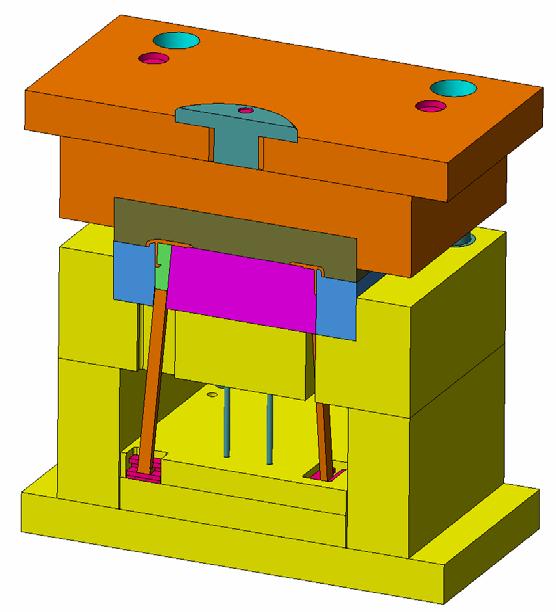
102 VISI Mould - Slide Assembly Creation Insert the correct parameters for the Angle Pin suitable for our requirements. Configure the parameters to match those shown below: - Make sure Core is the selected layer. Choose a 12mm diameter pin. Select an 100mm pin length. The incline angle of the Pin is 8 degrees. We require a minimum stroke of 1.4mm for the core pin to retract from the part. By typing in a minimum stroke the system calculates the achievable stroke based on the pin dimensions and angle. Components removed for illustration purposes. Slot Cavity The slot cavity is a pocket that can be configured when the angle pin is long enough to pass through the slide and needs relief in the core plate. Vcamtech Co., Ltd 12


103 VISI Mould - Slide Assembly Creation Exercise Create the same Slide Assembly in the other side of the mould tool. Following the previous example, now make an identical slide in the pocket on the opposite side of the tool. Here is what you should expect with both Slide Assemblies in position. This completes the section on Inserting Standard Elements into the Mould Assembly. In the next stages we will add some cooling channels to the Fixed Half of the tool. To make this process easier and more realistic we will open a more complete version of the Mould Tool that we have already worked on. This tool is almost identical to the one you have produced so far but contains slightly more standard elements. Vcamtech Co., Ltd 13


104 VISI Mould Cooling Channel Layout

105 Objectives VISI Mould - Cooling Channel Layout At this stage of the mould development it is time to design the cooling channel layout. For this task we will use a pre designed configuration that we can apply using the Simple Cooling concept which will turn a layout of simple segments into a solidified cooling circuit with hose connectors and o-rings. For this task we will begin with a much more complete tool design which contains the majority of the components and it is required to load the starter file as detailed below. Do not worry if you have not managed to complete the previous training exercises as the starter file will bring you right up to the correct point for this section. Loading the File Lets begin by opening the file required for this tutorial. Select the File Open command and select cooling-start.wkf Vcamtech Co., Ltd 1


106 VISI Mould - Cooling Channel Layout Cooling Channels Make sure that you have opened the starter file, this is a more complete version of the tool you have been working on in the previous exercises. It is important that you open this file in order to complete the cooling exercise. The first task we need to perform is to subtract all the cavity / clearance solids from the model to create actual holes. To do this, follow the next steps: - Select All. This will detect all the cavities to be removed. Apply the subtraction on all the solids in the model. Holes removed from solid Before we begin to insert cooling channels it is necessary to activate the relevant layers to make the task easier: - Activate only the Layers shown below. Make sure fh-cooling is the current layer Resulting display the black lines represent the proposed cooling channel layout. Vcamtech Co., Ltd 2


107 VISI Mould - Cooling Channel Layout Now let s begin to create the cooling channels. For this circuit we will use the Cooling Simple from the mould drop down menu. The default Cooling Simple interface will now appear. Click the Add Group icon, this will create a new cooling group. A New cooling group should be added to the cooling tree. Next modify the name of the group. Click into the Name box and rename the group as shown. Vcamtech Co., Ltd 3


108 VISI Mould - Cooling Channel Layout Before we add any cooling channels into the group, lets adjust one of the tolerances in the cooling configuration setup: - Click on the CFG icon from the tool bar to access the settings Adjust the range Tolerance to 5. Note: - The integrity tolerance represents the minimum distance the endpoint of a cooling channel can be from the face of a solid. The Range Tolerance is the maximum distance the endpoint of the cooling channel can be from the face of a solid. In this example all our channels are defined exactly in position, so adjusting this parameter eliminates unnecessary checking and warning messages. Click OK to continue. Adding the Channels to the Group Cooling Simple uses segments drawn in the normal CAD environment as the layout for the cooling design. The next step is to pick the cooling layout :- Note: - In our example the cooling layout has already been pre-drawn (shown on previous page) on the layer fh-cooling for convenience. Click on to the Add/ Select Channel Icon Click on to the Select All Icon. This will pick all the visible cooling elements, then click Yes at the next prompt to add the channels. Vcamtech Co., Ltd 4


109 VISI Mould - Cooling Channel Layout There should now be 14 channels in the list. Note: - When you use the Select All method of picking the channels, the channels may not be ordered logically in the tree. Also the green channels in the tree (7,8,12 and13) represent the vertical channels. Take note that the after selection of the channels the system will automatically split them where they pass through the faces of other plates. Vertical channel split into 2 pieces where it passes into the fixed half insert. Now that we have a list of channels in the Cooling Tree it is important for the system to recognise which channels are associated with which faces in the model. To do this we need to Split and Adapt the channels. This can be done as follows: - Click on to the Fixed Half Cooling Group icon at the top of the tree. Now select the Split /Adapt icon. Vcamtech Co., Ltd 5
 after you have performed this task :- This refers to Channel 11 and 14.")

110 VISI Mould - Cooling Channel Layout This will split and adapt all of the channels in the group that we have selected. You will receive the next message(s) after you have performed this task :- This refers to Channel 11 and 14. The system Checks channel 11 and 14 by theoretically extending the channels through the plate. In this case the channel passes through the sprue bush and reports a clash. Select Yes to continue. Dotted line shows the theoretical extension of the cooling channel that causes the collision check. Click on Yes to split the channel NOTE: - You will have to repeat the previous steps for channel 14 that has the same conditions as channel 11. Click on Yes to confirm that all the channels in the group have been split and adapted. Vcamtech Co., Ltd 6


111 Check the diameter of the cooling channels. The cooling tree should now look like the one shown below: - VISI Mould - Cooling Channel Layout Click on any node in the tree and look at the properties box. Check that the Diameter = 6 Solidify the cooling channels Now we are sure that the cooling channel diameters are 6mm, we can convert them into solid form. Follow the next steps: - Click on the Solidify icon from the toolbar and make sure you have selected the Fixed Half Cooling Node. You will now see the icon next to the channel change to indicate it has been solidified and the cooling channels appear on the model. Vcamtech Co., Ltd 7


112 VISI Mould - Cooling Channel Layout Adding Water Connectors to Channel 11 and 14 At this stage we will be adding water connectors to channels 11 and 14 Select Channel 11 from the tree. In the properties panel for Channel 11 click on the Browse icon in the Element 1 parameter box. Select the Z81 connector and adjust he parameters as shown below. Adjust the parameters shown in the highlighted boxes. The diagram below shows the hose connector and clearance holes in position on the channel. NOTE: - REPEAT THIS TASK FOR CHANNEL 14 NOTE: - Switch on the STANDARD layer is you cannot see the element. Vcamtech Co., Ltd 8


113 VISI Mould - Cooling Channel Layout At this stage you should have 2 connectors applied to channel 11 and 14 as shown below. Adding O rings HASCO Z98 to the vertical channels. The next task is to add some O ring seals to the vertical channels 12 and 13. Adjust the parameters shown in the highlighted boxes. Remember this has to be done for channels 12 and 13. O rings shown in position on vertical channels 12 and 13. Vcamtech Co., Ltd 9


114 VISI Mould - Cooling Channel Layout Adding Plugs to all other channels x 8 Now we have added the O rings to the vertical channels we will finish this circuit by adding some sealing plugs to the open ends of the remaining channels, denoted by the circles. The Channels required for this operation are shown below: In the properties panel for each channel click on the Browse icon in the Element 1 parameter box. Make sure that parameters match the ones shown opposite in highlight. Remember this must be done for each of the remaining 8 channels. The plug should look like the one shown below when applied. Vcamtech Co., Ltd 10


115 VISI Mould - Cooling Channel Layout The Result FH Cooling Channel Completed If you have followed the exercises correctly you should have a result similar to the one shown below. Exercise Add the cooling circuit for the Moving Half of the tool Now that you have performed this task for the fixed half of the tool why not try it on the Moving Half. The principle is exactly the same as the fixed half but this time there will be no step by step instructions. All cooling diameters and components will be specified for the channels. To start, activate the following 3 layers: - Make EJE1 the current layer Result of activating the 3 layers specified Vcamtech Co., Ltd 11

116 Next adjust the tolerances in the configuration files as shown below. VISI Mould - Cooling Channel Layout Click on the CFG icon from the tool bar to access the settings Now import the cooling layout This function allows the user to import cooling schematics into a file. The layout for the moving half has been pre-designed for your convenience and now we can import it. 0 Click on the Import icon from the tool bar to import the file. Browse for the file MH-Cooling.nct If you are unsure ask the tutor where this can be found..nct is the default file extension for cooling channels The application point for the cooling layout is shown below. The cooling channel history is now loaded into the tree. Remember to split and adapt the cooling channels. Vcamtech Co., Ltd 12


117 VISI Mould - Cooling Channel Layout Now use your knowledge and refer to the Fixed Half Cooling example to produce the following details on the moving half: - Cooling Diameter = 6mm Add the Z81 hose connectors as shown. Vcamtech Co., Ltd 13


118 Add 4 x O rings to the vertical channels as shown below: - VISI Mould - Cooling Channel Layout Note: - Apply the O rings to the lower vertical channels. Finally add the Plugs to the open ends of the remaining Channels. Vcamtech Co., Ltd 14

119 VISI Mould - Cooling Channel Layout Now activate all the layers on the model Click twice on this icon to Reset the layer list, making all layers active. Subtracting the Channels The last task we need to perform is to subtract all the cooling channels from the model to create actual holes. To do this, follow the next steps: - Select All. This will detect all the cavities to be removed. Apply the subtraction on all the solids in the model. Cooling holes removed from solid. With the cooling circuits completed the next stage is to make some 2D drawings and details of the tool. Vcamtech Co., Ltd 15
120 VISI Mould Creating Mould Tool Documentation
121 Objectives VISI Mould - Creating Mould Tool Documentation In this, the last section of the VISI-Mould training series, we will be creating some sample drawing sheets, including GA, sections and various views required for documenting the mould. Also included is a comprehensive overview of one particular strategy in creating a bill of materials / part ordering documentation. For this task we will begin from the last completed stage of the training and it is required to load the starter file as detailed below. Do not worry if you have not managed to complete the previous training exercises as the starter file will bring you right up to the correct point for this section. Loading the File Lets begin by opening the file required for this tutorial. Select the File Open command and select tool-drawings-start.wkf Vcamtech Co., Ltd 1
122 Creating GA and Detailed Views using Plotview. VISI Mould - Creating Mould Tool Documentation The following exercise will only give some ideas and pointers on what type of views to create and is not intended as a step by step guide to using the plot view, as this should have been covered comprehensively during the standard training course. Exercises Generate the Views Now generate the views shown in the following chapter. Remember this is not a step by step tutorial, you may need to refer to the Plot View training guide to refresh your memory on how to make the views, hints and tips will be given when needed. Please don t hesitate to ask if you are unsure: - These views to appear on Page 1 Fixed Section along the X axis Resulting Section Placed Below Plan View Vcamtech Co., Ltd 2

123 VISI Mould - Creating Mould Tool Documentation Make a variable section through the slide and lifters as shown below. These views to appear on Page 1 Hidden detail switched on to assist in section line creation. Result of the variable section. Now create a profile section through a pillar. The section line is simply a straight segment drawn in position and turned into an open profile. Vcamtech Co., Ltd 3

124 VISI Mould - Creating Mould Tool Documentation This is what Page 1 might look like after creating the views on an A0 page format. Now create a plan view of the Moving Half of the tool assembly on Page 2 Activate Page 2 from the plot view manager. Make sure the moving half group is activated. The moving half group contains all the layers relevant for the moving half. Access this from the Options tab. Vcamtech Co., Ltd 4
125 VISI Mould - Creating Mould Tool Documentation Now make the top view in the normal way and place the section as shown below. Plan View Of Moving Half and Required Section Try and make a section similar to that shown on the left. This section passes through a core pin and lifter. Suggested parameters for the section Vcamtech Co., Ltd 5

126 VISI Mould - Creating Mould Tool Documentation Now create a plan view of the Fixed Half of the tool assembly on Page 2 Again this view will be generated on page 2 placed to the right of the moving half Activate Page 2 from the plot view manager. Activate the fixed half group from the options menu The view below has been rotated around 180 degrees whilst placing the view. Hidden lines have been displayed on this view. Vcamtech Co., Ltd 6
127 VISI Mould - Creating Mould Tool Documentation Create a scrap section through the cooling channel showing hose connectors and o ring. Section is created from straight segment converted to an open profile. Result of the profile section. This is what Page 2 might look like after creating the views on an A0 page format. Vcamtech Co., Ltd 7

128 Adding A Bill of Materials Using Assembly Manager Loading the File Lets begin by opening the starter file required for this tutorial. VISI Mould - Creating Mould Tool Documentation Select the File Open command and select tool-complete-plots.wkf Now that we have created some 2D drawings form the 3D mould tool assembly, the final task is to generate the Bill Of Materials using Assembly Manager. The following exercises will show us how: - For this task we will plan in advance how we want to organise our bill of materials. For this particular mould tool we will divide the components in to logical families / groups of parts. The following example shows the families we require and the order they should appear in the list: - Mould Base - Bolster Plates, Bushes, Pillars Inserts - Any non-standard machined inserts Lifters - Lifter Heads and Ancillaries Sliders - Slides, Heals, Wear Plates, Rails etc. Injection / Ejection - Ejection Pins, Ejector guides, Sprue Bush etc Cooling - Hose connectors, Plugs, O Rings etc Screws - Screw Fixings Now we have decided how to break down the B.O.M lets begin the process in VISI using the assembly manager. This can be started from the Annotation Menu clicking on the Assembly Manager Item. The Assembly Manager Panel will appear on the right hand side, containing the list of parts and properties. If you expand one of the Cap Head Screw Sums you can see the items beneath just show a list of Cap Head Screws. Vcamtech Co., Ltd 8


129 VISI Mould - Creating Mould Tool Documentation Info: - If you click on to one of the items in the sum, you can reveal the properties for each part. Creating the Families for the relevant component groups. The first real task we need to complete is to make the families for the components we discussed at the start of this section. The next steps will show you how: - Right Mouse Click in the white area of the screen Select the Families > Create Family option from the menu. Now create the Mould Base family and select OK. The family will appear at the top of the tree as shown below. Now repeat the task for the other remaining families so the tree looks like the one below. This is how the tree should appear after the remaining families have been added. Vcamtech Co., Ltd 9


130 VISI Mould - Creating Mould Tool Documentation Adding Components to the appropriate Family Now that we have created all of the relevant families, it is time to add the correct components to each family. The example will show you how to perform the procedure for one family and its associated components. The Mould Base family will be used as the example: - Drag and Drop all the items shown below into the Mould Base family. Use the left mouse button to perform the drag and drop. When using Drag and Drop on Sum items, you are required to select the items in the sum using multi select. You cannot drag a Sum. You can Multi Select items to drag and drop using the Select Elements option. You should now have20 items in the Mould Base family, the display should look like the one below. Having dragged and dropped all the items into the Mould Base family you should now have a total of 20 items in the family as shown. Vcamtech Co., Ltd 10


131 VISI Mould - Creating Mould Tool Documentation Exercise Organise the remaining Families Having now successfully organised the Mould Base family please arrange the remaining families to look like those shown below using the drag and drop method. As you can see once we have consolidated all the families, the parts list becomes much easier to manage, your assembly manager window should be similar to the one shown below: - Seven Families should be present. These items are part of the plot view. (Masks and Profiles) This is the actual moulding, not required for the parts list. Vcamtech Co., Ltd 11


132 VISI Mould - Creating Mould Tool Documentation Configuring the parts list Now we have arranged the parts into logical families it is now time to start configuring how we want the parts list to appear, that is what fields we want displayed in the parts table. To do this, follow the next example: - Click on the Settings icon. Click on the Parts List position tab at the top of the interface. Now from the parts list position panel uncheck the fields as shown below. Here we are basically determining which fields will be present in B.O.M table. Once you have set the field types accept the changes as shown. We are now at a stage where we can begin to number the items and place them in a table. Vcamtech Co., Ltd 12


133 VISI Mould - Creating Mould Tool Documentation Numbering the Items using table mode Now from the main Assembly Manager toolbar switch to table mode to begin organising the B.O.M layout. Click on the Table icon. You will now be presented with the table mode interface Note the names of the column headers. Position, Quantity etc The components are ordered in the list according to the family name and position. The example below shows the cooling family and its relationship to the table. Scroll to the bottom of the list using the scroll bar arrow button. At the bottom of the list take note of items These are not required in the parts list as they represent the actual moulding and some 2D plot view information. Vcamtech Co., Ltd 13


134 Lets remove items from the parts list as follows. VISI Mould - Creating Mould Tool Documentation From the Assembly Manager tree, uncheck the items as shown opposite. They will subsequently be removed from the parts list. We will begin numbering the parts list focusing on one family at a time. Lets begin with the Mould Base family. Follow the next example to see how this is done. From the Assembly Manager tree, make sure that the Mould Base family is the only one checked in the list. Take a look at the parts list, items 1 12 represent the Mould Base family and are the only ones displayed. Lets assign position numbers and then re-arrange the order of the Mould Base family. LMB Click into Item 1 then click RMB and select the option Assign position. Assign a Position No.1 to the Bottom Clamping plate. You should have a result similar to that shown below for the clamping plate. Vcamtech Co., Ltd 14


 is shown below and")
135 VISI Mould - Creating Mould Tool Documentation Now repeat the task for all the items in the Mould Base family. Please make sure the numbers are assigned as follows: - Click on the Position column header as highlighted below to order the list in numerical order. The next family that we will number is the Insert family. Using the same method as previously described, number the family as follows: - Make sure Inserts is the only family checked. The numbering sequence (13-16) is shown below and follows on from the Mould Base family no s The next family that we will number is the Lifters family, please number the family as follows: - The numbering sequence (17-23) is shown below and follows on from the Insert family no s Vcamtech Co., Ltd 15
 is shown")

136 VISI Mould - Creating Mould Tool Documentation The next family that we will number is the Sliders family, please number the family as follows: - The numbering sequence (24-31) is shown below and follows on from the Insert family no s Now number the Injection / Ejection family to match the one shown below: - The numbering sequence (32-44) is shown below and follows on from the Sliders family no s Number the Cooling family as shown below: - The numbering sequence (45-47) is shown below and follows on from the Injection / Ejection family no s Finally, lets number the Screws family to complete the numbering sequence. Please see overleaf. Number the Screws family as shown below: - Vcamtech Co., Ltd 16


137 VISI Mould - Creating Mould Tool Documentation Click x 2 with the LMB on the Dimensions column header to group screw sizes together as shown. Now click on the set reset table selection icon to select the whole family. Click with the RMB anywhere on the table and select the Assign position option as shown. Assign the position as 48 and the system will increment the numbering sequence forwards through the empty positions. Vcamtech Co., Ltd 17


138 The Screws family is now complete with numbering from VISI Mould - Creating Mould Tool Documentation With all the numbering now completed for each family, it is time to view the full parts list and put it in Position Number order. Switch on all the families from the Assembly Manager tree. You can now see all of the parts displayed in the list. Click with the LMB on the Position header to order them as shown below. Vcamtech Co., Ltd 18


139 VISI Mould - Creating Mould Tool Documentation Add the B.O.M into the Plot View 2D drawing Switch to the Plot View mode as shown below and click onto Page 1 from the plot view pages list. Now restart the Assembly Manager with table mode active so that the screen looks like the one shown below. Please see overleaf for details of how to put the B.O.M onto the plot view page. Vcamtech Co., Ltd 19


140 VISI Mould - Creating Mould Tool Documentation From the right hand side of the parts list interface please make sure the parameters are set as shown below. Set the Text Height parameter to 4 Set the Row Sort to Bottom > Top so that the list is ordered with Position 1 at the bottom of the list. Click on the Plot Table icon From the Part list options dialogue make sure All rows is checked. This ensures the complete table will be created. Selecting OK will attach the parts list to your cursor at the bottom right hand corner of the table. Vcamtech Co., Ltd 20
VISI-Progress Step-by-Step Unfolding
 VISI-Progress Step-by-Step Unfolding VISI Progress - Unfolding Part Management This document has been provided to describe in detail the new unfolding routines and interfaces for VISI-Progress that have
Preface. Version 5 Release 5. Mold Tooling Design
 Version 5 Release 5 Mold Tooling Design Preface Getting Started Basic Tasks Advanced Tasks Customization Workbench Description Glossary Index Preface The CATIA Version 5 Mold Tooling Design application
VERO UK TRAINING MATERIAL. 2D CAM Training
 VERO UK TRAINING MATERIAL 2D CAM Training Vcamtech Co., Ltd 1 INTRODUCTION During this exercise, it is assumed that the user has a basic knowledge of the VISI-Series software. OBJECTIVE This tutorial has
VERO UK TRAINING MATERIAL
 VERO UK TRAINING MATERIAL VISI Basic 2-D Modelling course (V-16) VISI Modelling 2D Design Introduction Many component designs follow a similar route, beginning with a 2D design, part modelled using solids
Constructing treatment features
 Constructing treatment features Publication Number spse01530 Constructing treatment features Publication Number spse01530 Proprietary and restricted rights notice This software and related documentation
Introduction to SolidWorks for Technology. No1: Childs Toy
 Introduction to SolidWorks for Technology No1: Childs Toy Table of Contents Table of Contents... 1 Introduction... 2 Part Modelling: Cab... 3 Part Modelling: Base... 6 Part Modelling: Wheel... 12 Assembly:
Introduction to SolidWorks Basics Materials Tech. Wood
 Introduction to SolidWorks Basics Materials Tech. Wood Table of Contents Table of Contents... 1 Book End... 2 Introduction... 2 Learning Intentions... 2 Modelling the Base... 3 Modelling the Front... 10
3 AXIS STANDARD CAD. BobCAD-CAM Version 28 Training Workbook 3 Axis Standard CAD
 3 AXIS STANDARD CAD This tutorial explains how to create the CAD model for the Mill 3 Axis Standard demonstration file. The design process includes using the Shape Library and other wireframe functions
Chapter 4 Feature Design Tree
 4-1 Chapter 4 Feature Design Tree Understand Feature Interactions Use the FeatureManager Design Tree Modify and Update Feature Dimensions Perform History-Based Part Modifications Change the Names of Created
Solidworks 2006 Surface-modeling
 Solidworks 2006 Surface-modeling (Tutorial 2-Mouse) Surface-modeling Solid-modeling A- 1 Assembly Design Design with a Master Model Surface-modeling Tutorial 2A Import 2D outline drawing into Solidworks2006
Lesson 4: Surface Re-limitation and Connection
 Lesson 4: Surface Re-limitation and Connection In this lesson you will learn how to limit the surfaces and form connection between the surfaces. Lesson contents: Case Study: Surface Re-limitation and Connection
1 - Introduction Training Guide Objectives WorkXplore Environment Importing and Opening CAD Files 5
 Table Of Contents 1.1 - Training Guide Objectives Table Of Contents 1 - Introduction 3 1.1 - Training Guide Objectives... 3 1.2 - WorkXplore Environment... 3 2 - Importing and Opening CAD Files 5 2.1 -
CATIA Surface Design
 CATIA V5 Training Exercises CATIA Surface Design Version 5 Release 19 September 2008 EDU_CAT_EN_GS1_FX_V5R19 Table of Contents (1/2) Creating Wireframe Geometry: Recap Exercises 4 Creating Wireframe Geometry:
Lesson 1 Parametric Modeling Fundamentals
 1-1 Lesson 1 Parametric Modeling Fundamentals Create Simple Parametric Models. Understand the Basic Parametric Modeling Process. Create and Profile Rough Sketches. Understand the "Shape before size" approach.
Solid Bodies and Disjointed bodies
 Solid Bodies and Disjointed bodies Generally speaking when modelling in Solid Works each Part file will contain single solid object. As you are modelling, each feature is merged or joined to the previous
Piping Design. Site Map Preface Getting Started Basic Tasks Advanced Tasks Customizing Workbench Description Index
 Piping Design Site Map Preface Getting Started Basic Tasks Advanced Tasks Customizing Workbench Description Index Dassault Systèmes 1994-2001. All rights reserved. Site Map Piping Design member member
Mechanical Design V5R19 Update
 CATIA V5 Training Foils Mechanical Design V5R19 Update Version 5 Release 19 August 2008 EDU_CAT_EN_MD2_UF_V5R19 1 About this course Objectives of the course Upon completion of this course you will be able
Maya Lesson 3 Temple Base & Columns
 Maya Lesson 3 Temple Base & Columns Make a new Folder inside your Computer Animation Folder and name it: Temple Save using Save As, and select Incremental Save, with 5 Saves. Name: Lesson3Temple YourName.ma
Solid Bodies and Disjointed Bodies
 Solid Bodies and Disjointed Bodies Generally speaking when modelling in Solid Works each Part file will contain single solid object. As you are modelling, each feature is merged or joined to the previous
Exercise Guide. Published: August MecSoft Corpotation
 VisualCAD Exercise Guide Published: August 2018 MecSoft Corpotation Copyright 1998-2018 VisualCAD 2018 Exercise Guide by Mecsoft Corporation User Notes: Contents 2 Table of Contents About this Guide 4
Quick Start Tutorial
 Tutorial Tutorial: Build an Apple Welcome to Design 3D CX 7. This is a quick tutorial to get you started. In this tutorial you ll learn how to import an Adobe Illustrator file, Lathe it into a 3D object,
MOLD DESIGN. Presented by: Nakul Singh, Tim Ralph, Jamie Curtis and Tim Winsor
 MOLD DESIGN Presented by: Nakul Singh, Tim Ralph, Jamie Curtis and Tim Winsor Mold Design Three main components: (a) Core This duplicates the inner surface of the model. It is larger than the finished
Feature-based CAM software for mills, multi-tasking lathes and wire EDM. Getting Started
 Feature-based CAM software for mills, multi-tasking lathes and wire EDM www.featurecam.com Getting Started FeatureCAM 2015 R3 Getting Started FeatureCAM Copyright 1995-2015 Delcam Ltd. All rights reserved.
Chapter 2 Parametric Modeling Fundamentals
 2-1 Chapter 2 Parametric Modeling Fundamentals Create Simple Extruded Solid Models Understand the Basic Parametric Modeling Procedure Create 2-D Sketches Understand the Shape before Size Approach Use the
Create Complex Surfaces
 Create Complex Surfaces In this lesson, you will be introduced to the functionalities available in the Generative Surface Design workbench. Lesson content: Case Study: Surface Design Design Intent Stages
Autodesk Fusion 360 Training: The Future of Making Things Attendee Guide
 Autodesk Fusion 360 Training: The Future of Making Things Attendee Guide Abstract After completing this workshop, you will have a basic understanding of editing 3D models using Autodesk Fusion 360 TM to
Additional Exercises. You will perform the following exercises to practice the concepts learnt in this course:
 Additional Exercises You will perform the following exercises to practice the concepts learnt in this course: Master Exercise : Mobile Phone Plastic Bottle Exercise 1 Master Exercise : Mobile Phone In
Focus On Your Strengths. Stand Out From The Crowd. Reach Your Goals. Cultivate Productivity. Our Commitment
 Focus On Your Strengths You know what differentiates your company from your competitors. We can help you build on those core strengths to reach your potential and maximize your benefits to your customers.
4) Finish the spline here. To complete the spline, double click the last point or select the spline tool again.
 Finish the spline here. To complete the spline, double click the last point or select the spline tool again.") 1) Select the line tool 3) Move the cursor along the X direction (be careful to stay on the X axis alignment so that the line is perpendicular) and click for the second point of the line. Type 0.5 for
1) Select the line tool 3) Move the cursor along the X direction (be careful to stay on the X axis alignment so that the line is perpendicular) and click for the second point of the line. Type 0.5 for
Tutorial VCarving Christmas Decorations
 Getting Started With Tutorial VCarving Christmas Decorations VCarve Pro Disclaimer All CNC machines (routing, engraving, and milling) are potentially dangerous and because Vectric Ltd has no control over
Design a Simple Fan in 123D Design
 Design a Simple Fan in 123D Design Learn to use 123D Design to make and print this simple fan. 123D Design is a free, powerful, yet simple 3D creation and editing tool. It allows you to design and build
Autodesk Inventor Design Exercise 2: F1 Team Challenge Car Developed by Tim Varner Synergis Technologies
 Autodesk Inventor Design Exercise 2: F1 Team Challenge Car Developed by Tim Varner Synergis Technologies Tim Varner - 2004 The Inventor User Interface Command Panel Lists the commands that are currently
SolidWorks Intro Part 1b
 SolidWorks Intro Part 1b Dave Touretzky and Susan Finger 1. Create a new part We ll create a CAD model of the 2 ½ D key fob below to make on the laser cutter. Select File New Templates IPSpart If the SolidWorks
Skateboard. Hanger. in the Feature Manager and click Sketch on the Context toolbar, Fig. 1. Fig. 2
 Chapter 3 Skateboard Hanger A. Sketch1 Lines. Step 1. Click File Menu > New, click Part Metric and OK. Step 2. Click Right Plane in the Feature Manager and click Sketch on the Context toolbar, Fig. 1.
Autodesk Fusion 360: Model. Overview. Modeling techniques in Fusion 360
 Overview Modeling techniques in Fusion 360 Modeling in Fusion 360 is quite a different experience from how you would model in conventional history-based CAD software. Some users have expressed that it
This lab exercise has two parts: (a) scan a part using a laser scanner, (b) construct a surface model from the scanned data points.
 scan a part using a laser scanner, (b) construct a surface model from the scanned data points.") 1 IIEM 215: Manufacturing Processes I Lab 4. Reverse Engineering: Laser Scanning and CAD Model construction This lab exercise has two parts: (a) scan a part using a laser scanner, (b) construct a surface
1 IIEM 215: Manufacturing Processes I Lab 4. Reverse Engineering: Laser Scanning and CAD Model construction This lab exercise has two parts: (a) scan a part using a laser scanner, (b) construct a surface
CHAPTER 1. EZ-MILL PRO / 3D MACHINING WIZARD TUTORIAL 1-2
 1. TABLE OF CONTENTS 1. TABLE OF CONTENTS 1 CHAPTER 1. EZ-MILL PRO / 3D MACHINING WIZARD TUTORIAL 1-2 Overview... 1-2 Cavity Machining... 1-2 Basic Programming Steps... 1-3 The Part... 1-4 Setting the
AutoCAD 2009 Tutorial
 AutoCAD 2009 Tutorial Second Level: 3D Modeling Randy H. Shih Oregon Institute of Technology SDC PUBLICATIONS Schroff Development Corporation www.schroff.com Better Textbooks. Lower Prices. AutoCAD 2009
Autodesk Inventor 2016
 Parametric Modeling with Autodesk Inventor 2016 Randy H. Shih SDC PUBLICATIONS Better Textbooks. Lower Prices. www.sdcpublications.com Powered by TCPDF (www.tcpdf.org) Visit the following websites to learn
Obtaining Meshable Surfaces
 Chapter 2 Obtaining Meshable Surfaces Exercise 2a: Importing and Repairing CAD Geometry Overview of Exercise Strategy: Import CAD geometry and organize your model using the Assembly Hierarchy. Evaluate
Licom Systems Ltd., Training Course Notes. 3D Surface Creation
 , Training Course Notes Work Volume and Work Planes...........................1 Overview..........................................1 Work Volume....................................1 Work Plane......................................1
Tutorial 1 Engraved Brass Plate R
 Getting Started With Tutorial 1 Engraved Brass Plate R4-090123 Table of Contents What is V-Carving?... 2 What the software allows you to do... 3 What file formats can be used?... 3 Getting Help... 3 Overview
CATIA V5 Parametric Surface Modeling
 CATIA V5 Parametric Surface Modeling Version 5 Release 16 A- 1 Toolbars in A B A. Wireframe: Create 3D curves / lines/ points/ plane B. Surfaces: Create surfaces C. Operations: Join surfaces, Split & Trim
Training Guide Getting Started with WorkXplore 3D
 Training Guide Getting Started with WorkXplore 3D Table of Contents Table of Contents 1 Training Guide Objectives 1-1 2 WorkXplore 3D Environment 2-1 3 Importing and Opening CAD Files 3-1 3.1 Importing
NC Manufacturing Verification
 NC Manufacturing Verification Overview Conventions What's New? User Tasks Accessing NC Manufacturing Verification Comparing the Machined Stock Part and the Design Part Pick Point Analysis in Video Mode
FreeStyle Shaper & Optimizer
 FreeStyle Shaper & Optimizer Preface What's New Getting Started Basic Tasks Advanced Tasks Workbench Description Customizing Glossary Index Dassault Systèmes 1994-99. All rights reserved. Preface CATIA
SolidWorks Implementation Guides. User Interface
 SolidWorks Implementation Guides User Interface Since most 2D CAD and SolidWorks are applications in the Microsoft Windows environment, tool buttons, toolbars, and the general appearance of the windows
NC Manufacturing Verification
 NC Manufacturing Verification Page 1 Preface Using This Guide Where to Find More Information Conventions What's New? User Tasks Accessing NC Manufacturing Verification Comparing the Machined Stock Part
Adding Fillet, Shell, and Draft Features
 Learn how to: Adding Fillet, Shell, and Draft Features I-DEAS Tutorials: Fundamental Skills add draft features add fillet features use the Ball Corner Fillet option add shell features Before you begin...
SolidCAM Training Course: Turning & Mill-Turn
 SolidCAM Training Course: Turning & Mill-Turn imachining 2D & 3D 2.5D Milling HSS HSM Indexial Multi-Sided Simultaneous 5-Axis Turning & Mill-Turn Solid Probe SolidCAM + SolidWorks The Complete Integrated
SolidWorks 2½D Parts
 SolidWorks 2½D Parts IDeATe Laser Micro Part 1b Dave Touretzky and Susan Finger 1. Create a new part In this lab, you ll create a CAD model of the 2 ½ D key fob below to make on the laser cutter. Select
SolidWorks 2015 User Interface
 SolidWorks 2015 User Interface SolidWorks a Dassault Systèmes Product Starting SolidWorks 1) On the desktop, double-click or from the start menu select: All Programs SOLIDWORKS 2015 SOLIDWORKS 2015. 2)
SolidWorks 2009 & DCG Student Assignment
 SolidWorks 2009 & DCG Student Assignment RD10 DCG Design & Communication Graphics 1 SolidWorks 2009 & DCG Student Assignment Table of Contents Focus of the lesson. 3 Getting Started Modelling the TV Plate
3D Modeler Creating Custom myhouse Symbols
 3D Modeler Creating Custom myhouse Symbols myhouse includes a large number of predrawn symbols. For most designs and floorplans, these should be sufficient. For plans that require that special table, bed,
Modeling a Gear Standard Tools, Surface Tools Solid Tool View, Trackball, Show-Hide Snaps Window 1-1
 Modeling a Gear This tutorial describes how to create a toothed gear. It combines using wireframe, solid, and surface modeling together to create a part. The model was created in standard units. To begin,
Electrical 3D Design & Documentation
 Electrical 3D Design & Documentation Page 1 Overview Conventions User Tasks Using Electrical 3D Design & Documentation Entering the Electrical Assembly Design Workbench Entering the Electrical Part Design
e b f SOLIDWORKS ESSENTIALS 1) SOLIDWORKS USER INTERFACE SUBJECT: USER INTERFACE KEYWORDS: ESSENTIALS/ FUNDAMENTALS a) The Graphics Area
 SOLIDWORKS USER INTERFACE SUBJECT: USER INTERFACE KEYWORDS: ESSENTIALS/ FUNDAMENTALS a) The Graphics Area") SUBJECT: USER INTERFACE KEYWORDS: ESSENTIALS/ FUNDAMENTALS SOLIDWORKS ESSENTIALS The aim of this document is to provide additional reference material to allow new users of SolidWorks to navigate through
SUBJECT: USER INTERFACE KEYWORDS: ESSENTIALS/ FUNDAMENTALS SOLIDWORKS ESSENTIALS The aim of this document is to provide additional reference material to allow new users of SolidWorks to navigate through
QuickTutor. An Introductory SilverScreen Modeling Tutorial. Solid Modeler
 QuickTutor An Introductory SilverScreen Modeling Tutorial Solid Modeler TM Copyright Copyright 2005 by Schroff Development Corporation, Shawnee-Mission, Kansas, United States of America. All rights reserved.
QDA Miner. Addendum v2.0
 QDA Miner Addendum v2.0 QDA Miner is an easy-to-use qualitative analysis software for coding, annotating, retrieving and reviewing coded data and documents such as open-ended responses, customer comments,
Introduction And Overview ANSYS, Inc. All rights reserved. 1 ANSYS, Inc. Proprietary
 Introduction And Overview 2006 ANSYS, Inc. All rights reserved. 1 ANSYS, Inc. Proprietary The ANSYS Workbench represents more than a general purpose engineering tool. It provides a highly integrated engineering
USING THE TRIBALL FOR POSITIONING
 USING THE TRIBALL FOR POSITIONING Although many important positioning tools are available, none are as versatile as the TriBall tool. This TriBall tool offers complete repositioning of many items: Shapes
1 In the Mini Window Editor, double-click phase 1 (GF-Wall-External) to make it current:
 to make it current:") 1 This Quick Start tutorial introduces you to the basics of creating an intelligent drawing using the BIM components supplied with MicroGDS 2010. Here we demonstrate how to construct the external walls
1 This Quick Start tutorial introduces you to the basics of creating an intelligent drawing using the BIM components supplied with MicroGDS 2010. Here we demonstrate how to construct the external walls
Multiframe Windows Version 16. User Manual
 Multiframe Windows Version 16 User Manual Bentley Systems, Incorporated 2013 License & Copyright Multiframe Program & User Manual 2013 Bentley Systems, Incorporated iii Table of Contents License & Copyright...
2 Solutions Chapter 3. Chapter 3: Practice Example 1
 1 Solutions This section includes the step by step solutions for the practice exercise for the following chapters and sections: Chapter 3 Chapter 4 Chapter 5 Chapter 11: Rainbow Springs sample test Final
Parametric Modeling with. Autodesk Fusion 360. First Edition. Randy H. Shih SDC. Better Textbooks. Lower Prices.
 Parametric Modeling with Autodesk Fusion 360 First Edition Randy H. Shih SDC PUBLICATIONS Better Textbooks. Lower Prices. www.sdcpublications.com Powered by TCPDF (www.tcpdf.org) Visit the following websites
Inventor 201. Work Planes, Features & Constraints: Advanced part features and constraints
 Work Planes, Features & Constraints: 1. Select the Work Plane feature tool, move the cursor to the rim of the base so that inside and outside edges are highlighted and click once on the bottom rim of the
1 - Introduction Training Guide Objectives WorkXplore Environment Importing and Opening CAD Files 5
 Table Of Contents 1.1 - Training Guide Objectives Table Of Contents 1 - Introduction 3 1.1 - Training Guide Objectives... 3 1.2 - WorkXplore Environment... 3 2 - Importing and Opening CAD Files 5 2.1 -
Electrical Harness Flattening
 Electrical Harness Flattening Overview Conventions What's New? Getting Started Accessing the Electrical Harness Flattening Workbench Defining the Harness Flattening Parameters Extracting Data Flattening
Selective Space Structures Manual
 Selective Space Structures Manual February 2017 CONTENTS 1 Contents 1 Overview and Concept 4 1.1 General Concept........................... 4 1.2 Modules................................ 6 2 The 3S Generator
Parametric Modeling. With. Autodesk Inventor. Randy H. Shih. Oregon Institute of Technology SDC PUBLICATIONS
 Parametric Modeling With Autodesk Inventor R10 Randy H. Shih Oregon Institute of Technology SDC PUBLICATIONS Schroff Development Corporation www.schroff.com www.schroff-europe.com 2-1 Chapter 2 Parametric
Publication Number spse01695
 XpresRoute (tubing) Publication Number spse01695 XpresRoute (tubing) Publication Number spse01695 Proprietary and restricted rights notice This software and related documentation are proprietary to Siemens
Module 4B: Creating Sheet Metal Parts Enclosing The 3D Space of Right and Oblique Pyramids With The Work Surface of Derived Parts
 Inventor (5) Module 4B: 4B- 1 Module 4B: Creating Sheet Metal Parts Enclosing The 3D Space of Right and Oblique Pyramids With The Work Surface of Derived Parts In Module 4B, we will learn how to create
SOLIDWORKS 2016 and Engineering Graphics
 SOLIDWORKS 2016 and Engineering Graphics An Integrated Approach Randy H. Shih SDC PUBLICATIONS Better Textbooks. Lower Prices. www.sdcpublications.com Powered by TCPDF (www.tcpdf.org) Visit the following
Introduction to ANSYS DesignModeler
 Lecture 9 Beams and Shells 14. 5 Release Introduction to ANSYS DesignModeler 2012 ANSYS, Inc. November 20, 2012 1 Release 14.5 Beams & Shells The features in the Concept menu are used to create and modify
Creo MOLDESIGN. Prerequisites. Stats
 Creo MOLDESIGN Creo MOLDESIGN tutorials have been developed with great emphasis on the practical application of the software to solve real world problems. The self-study course starts from the very basic
Unit 21 - Creating a Navigation Bar in Macromedia Fireworks
 Unit 21 - Creating a Navigation Bar in Macromedia Fireworks Items needed to complete the Navigation Bar: Unit 21 - House Style Unit 21 - Graphics Sketch Diagrams Document ------------------------------------------------------------------------------------------------
Publication Number spse01695
 XpresRoute (tubing) Publication Number spse01695 XpresRoute (tubing) Publication Number spse01695 Proprietary and restricted rights notice This software and related documentation are proprietary to Siemens
Equipment Support Structures
 Equipment Support Structures Overview Conventions What's New? Getting Started Setting Up Your Session Creating a Simple Structural Frame Creating Non-uniform Columns Creating Plates with Openings Bracing
Podium Plus Data Analysis Software. User Manual. SWIS10 Version
 SWIS10 Version Issue 1.10 February 2005 Contents 1 Introduction 6 1.1 What is Podium Plus? 6 1.2 About This Manual 6 1.3 Typographical Conventions 7 1.4 Getting Technical Support 7 2 Getting Started 8
Section 3 Formatting
 Section 3 Formatting ECDL 5.0 Section 3 Formatting By the end of this Section you should be able to: Apply Formatting, Text Effects and Bullets Use Undo and Redo Change Alignment and Spacing Use Cut, Copy
Getting Started with Alibre CAM. Tutorial 12: Engraving on a Cylinder
 Getting Started with Alibre CAM Tutorial 12: Engraving on a Cylinder 344 Introduction This tutorial will illustrate engraving text on a cylinder using a 4 Axis Engraving operation. The stepped instructions
Introduction To Finite Element Analysis
 Creating a Part In this part of the tutorial we will introduce you to some basic modelling concepts. If you are already familiar with modelling in Pro Engineer you will find this section very easy. Before
Advance Design. Tutorial
 TUTORIAL 2018 Advance Design Tutorial Table of Contents About this tutorial... 1 How to use this guide... 3 Lesson 1: Preparing and organizing your model... 4 Step 1: Start Advance Design... 5 Step 2:
BoA Tools Page 1 / 31
 BoA Tools Page 1 / 31 Standard tools Overview 2 Work pane 3 3D-2D file Main palette 6 Layout Main Palette 9 Navigation tools 11 Workplane Palette 14 Cursor Palette 21 Numeric control 24 Selection by Criteria
SOLIDWORKS: Lesson III Patterns & Mirrors. UCF Engineering
 SOLIDWORKS: Lesson III Patterns & Mirrors UCF Engineering Solidworks Review Last lesson we discussed several more features that can be added to models in order to increase their complexity. We are now
CPM-200 User Guide For Lighthouse for MAX
 CPM-200 User Guide For Lighthouse for MAX Contents Page Number Opening the software 2 Altering the page size & Orientation 3-4 Inserting Text 5 Editing Text 6 Inserting Graphics 7-8 Changing the Colour
A Step-by-step guide to creating a Professional PowerPoint Presentation
 Quick introduction to Microsoft PowerPoint A Step-by-step guide to creating a Professional PowerPoint Presentation Created by Cruse Control creative services Tel +44 (0) 1923 842 295 training@crusecontrol.com
VisualMILL Getting Started Guide
 VisualMILL Getting Started Guide Welcome to VisualMILL Getting Started Guide... 4 About this Guide... 4 Where to go for more help... 4 Tutorial 1: Machining a Gasket... 5 Introduction... 6 Preparing the
[Type text] [Type text] [Type text] GearPro Procedure
![[Type text] [Type text] [Type text] GearPro Procedure](/thumbs/77/76062303.jpg "[Type text] [Type text] [Type text] GearPro Procedure") GearPro Procedure Pictured below is the GearPro main screen. In this manual the icons on the top right corner (Chapter 1), far left side (Chapters 2-5), and far right side (Chapters 6&7) will be discussed.
GearPro Procedure Pictured below is the GearPro main screen. In this manual the icons on the top right corner (Chapter 1), far left side (Chapters 2-5), and far right side (Chapters 6&7) will be discussed.
Alibre Design Tutorial - Simple Revolve Translucent Glass Lamp Globe
 Alibre Design Tutorial - Simple Revolve Translucent Glass Lamp Globe Part Tutorial Exercise 2: Globe-1 In this Exercise, We will set System Parameters first. Then, in sketch mode, we will first Outline
Create a Rubber Duck. This tutorial shows you how to. Create simple surfaces. Rebuild a surface. Edit surface control points. Draw and project curves
 Page 1 of 24 Create a Rubber Duck This exercise focuses on the free form, squishy aspect. Unlike the flashlight model, the exact size and placement of the objects is not critical. The overall form is the
LAB # 2 3D Modeling, Properties Commands & Attributes
 COMSATS Institute of Information Technology Electrical Engineering Department (Islamabad Campus) LAB # 2 3D Modeling, Properties Commands & Attributes Designed by Syed Muzahir Abbas 1 1. Overview of the
Module 5: Creating Sheet Metal Transition Piece Between a Square Tube and a Rectangular Tube with Triangulation
 1 Module 5: Creating Sheet Metal Transition Piece Between a Square Tube and a Rectangular Tube with Triangulation In Module 5, we will learn how to create a 3D folded model of a sheet metal transition
Dolphin PartMaster Wire EDM
 Dolphin PartMaster Wire EDM Copyright 2000-2017 Dolphin CADCAM Systems Ltd. This document is copyrighted and all rights are reserved. This document may not, in whole or in part, be copied or reproduced
Using Tables, Sparklines and Conditional Formatting. Module 5. Adobe Captivate Wednesday, May 11, 2016
 Slide 1 - Using Tables, Sparklines and Conditional Formatting Using Tables, Sparklines and Conditional Formatting Module 5 Page 1 of 27 Slide 2 - Lesson Objectives Lesson Objectives Explore the find and
GETTING STARTED WITH MASTERCAM SOLIDS
 GETTING STARTED WITH MASTERCAM SOLIDS June 2017 GETTING STARTED WITH MASTERCAM SOLIDS June 2017 2017 CNC Software, Inc. All rights reserved. Software: Mastercam 2018 Terms of Use Use of this document is
Tutorial Second Level
 AutoCAD 2018 Tutorial Second Level 3D Modeling Randy H. Shih SDC PUBLICATIONS Better Textbooks. Lower Prices. www.sdcpublications.com Powered by TCPDF (www.tcpdf.org) Visit the following websites to learn
Module 2 Review. Assemblies and Rendering. Why Use Assemblies. Assemblies - Key Concepts. Sketch Planes Sketched Features.
 Module 2 Review Assemblies and Rendering EF 101 Modules 3.1, 3.2 Sketch Planes Sketched Features Extrude, Revolve Placed Features Hole, Fillet, Chamfer, Shell, Rect. Pattern Drawing Views Base, Ortho,
Introduction to AutoCAD 2012
 Introduction to AutoCAD 2012 Alf Yarwood Chapter 13 Exercise 1 1. Open AutoCAD 2012 with a double-click on its shortcut icon in the Windows desktop. 2. Open the template acadiso3d.dwt. 3. Make two new
TRAINING SESSION Q3 2016
 There are 6 main topics in this training session which is focusing on 3D Import and 2D Drawing Tips and Tricks in IRONCAD. Content 3D modeling kernels... 2 3D Import... 3 Direct Face Modeling... 5 Unfold