Introduction to AutoCAD 2012
|
|
|
- Norah Adams
- 6 years ago
- Views:
Transcription


1 Introduction to AutoCAD 2012 Alf Yarwood Chapter 13 Exercise 1 1. Open AutoCAD 2012 with a double-click on its shortcut icon in the Windows desktop. 2. Open the template acadiso3d.dwt. 3. Make two new layer one of colour Yellow, the second of colour Cyan. Make layer Yellow current. 4. Left-click Named in View/Viewports panel. Page 1 5. The Viewports dialog appears. In the Standard viewports list pick Three: Right. Make sure that in the Setup popup list 3D is selected. 6. Left-click the OK button of the dialog. The dialog disappears from screen and the AutoCAD window shows a Three: Right viewports setup. 7. Left-click in the Top (bottom left) viewport to make it active.

![radius for base of cylinder or [Diameter]: enter 60 rightclick Specify height of cylinder or [Center of other end]: enter 150 rightclick Command: 9.](/docs-images/71/65973691/images/2-1.jpg "Left-click the Sphere tool icon in the Home panel.")
![The command line shows: Command: _sphere Current wire frame density: ISOLINES=4 Specify center of sphere <0,0,0>: pick centre of cylinder Specify radius of sphere or [Diameter]:](/docs-images/71/65973691/images/2-2.jpg "enter 60 right-click Command: 10. Left-click in the Front (top left) viewport to make it active. 11.")
2 Page 2 8. Left-click the Cylinder tool icon in the Home panel. The command line shows: Command: _cylinder Current wire frame density: ISOLINES=4 Specify center point for base of cylinder or [Elliptical] <0,0,0>: pick a central point Specify radius for base of cylinder or [Diameter]: enter 60 rightclick Specify height of cylinder or [Center of other end]: enter 150 rightclick Command: 9. Left-click the Sphere tool icon in the Home panel. The command line shows: Command: _sphere Current wire frame density: ISOLINES=4 Specify center of sphere <0,0,0>: pick centre of cylinder Specify radius of sphere or [Diameter]: enter 60 right-click Command: 10. Left-click in the Front (top left) viewport to make it active. 11. With the Move tool, move the sphere vertically into its correct position relative to the cylinder. 12. With the Union tool from the Home/Solid Editing panel form a union of the two solids. 13. Call the Box tool with a left-click on its tool icon in the Home panel. Material accompanying Introduction to AutoCAD 2012, ISBN Copyright 2011, Alf Yarwood.


3 Page In the Plan view construct a box as follows: Command: _box Specify corner of box or [CEnter] <0,0,0>: pick Specify corner or [Cube/Length]: pick Specify height: enter 15 right-click Command: 15. In the Front viewport, with the Move tool, move the box vertically to a good position. 16. Call Subtract with a left-click on its tool icon in the Home/Solid Editing panel and subtract the mouth from the head. 17. Make the Cyan layer current. In the Top viewport, construct two spheres of radius 5 for the eyes and with Move, move them into position in the head. 18. Make the Isometric viewport current, call the Fillet tool and fillet the base of the cylinder of the head to a radius of Add another cylinder for the neck and join with Union join it to he head. 20. Using the Wedge tool from the Home panel construct a wedge for the nose in the Top viewport, fillet its edges, then rotate and move to a good position. Then join to the head using Union. 21. In the isometric viewport select Conceptual from Visual Styles. 22. Save the model drawing to a memory stick with the file name 13_Exercise01.dwg. 23. Close the drawing window.

4 Page 4 Chapter 13 Exercise 2 1. Open AutoCAD 2012 with a double-click on its shortcut icon in the Windows desktop. 2. Open the template acadiso3d.dwt. Make a new layer colour Blue and make the layer current. 3. Select New from the View/Viewports panel and from the Viewports dialog select Four: Equal with Setup set to 3D. 4. Set ISOLINES to In the Front (top right) viewport, with the Sphere tool from the Home panel, construct a sphere of radius Construct boxes using the Box tool from the Home panel on each side of the sphere in the Right (top left) viewport, with one side 35 units from the centre of the sphere and subtract the boxes from the sphere using the Subtract tool from the Home/Solid Editing panel. 7. In the Plan (bottom right) viewport, construct three cylinders to sizes as given in Fig In suitable viewports and with the Move tool, move the cylinders to their correct places relative to each other and to the main model. 8. Form a union of the diameter 50 and 40 cylinders and subtract the smallest of the three cylinders from the union. 9. Call the Array tool from the Home/Modify panel and polar array the cylinder four times around the centre of the truncated sphere. 10. With the Union tool from the Home/Solid Editing panel form a union of the five objects. 11. In the Right viewport, construct a sphere of radius 25 and subtract it from the union. 12. In other viewports with the Move tool, move the sphere to its correct position in relation to the union. 13. Subtract the sphere from the union. 14. Save the model drawing to a memory stick with the file name 13_Exercise02.dwg. 15. Close the drawing window.


5 Page 5 Material accompanying Introduction to AutoCAD 2011, ISBN Copyright 2010, Alf Yarwood. Published by Elsevier Ltd. All rights reserved
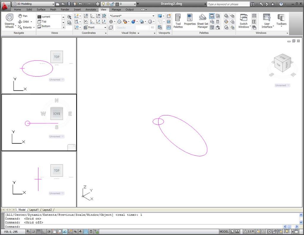
 viewport, construct the circle. 6. In the Front (top left) viewport, construct the ellipse. 7.")
6 Page 6 Chapter 13 Exercise 3 1. Open AutoCAD 2012 with a double-click on its shortcut icon in the Windows desktop. 2. Open the template acadiso3d.dwt. 3. Make a new layer Outlines of colour magenta and make it the current layer. 4. Place the AutoCAD window in Four: Left viewports, with a setup of 3D. 5. In the Top (centre left) viewport, construct the circle. 6. In the Front (top left) viewport, construct the ellipse. 7. Move the ellipse into its correct position with one axis end central to the circle. 8. Set ISOLINES to Make layer 0 current and the Isometric viewport current. 10. Call the Extrude tool from the Home panel. The command line shows: Command: _extrude Current wire frame density: ISOLINES=8 Select objects: pick the circle 1 found Select objects: right-click Specify height of extrusion or [Path]: enter p right-click Select extrusion path or [Taper angle]: pick the ellipse Command: 11. Working between the viewports and using the Copy tool, copy the link and rotate the link through Again working between the viewports and using Zoom where necessary, move the copied, rotated link in line with the first link. 13. With Copy tool copy the two links to make six in all. 14. In the Isometric viewport select Conceptual from Visual Styles. 15. Save your model drawing to the file name 13_Exercise03.dwg in a memory stick. 16. Close the drawing window.
7 Page 7
8 Page 8 Chapter 13 Exercise 4 1. Open AutoCAD 2012 with a double-click on its shortcut icon in the Windows desktop. 2. Open the template acadiso3d.dwt. Make a new layer Outlines of colour magenta. 3. Place the AutoCAD window in a Four: Equal viewport setup. 4. On the layer Outlines and in the Front (top right) viewport, construct a front view closed polyline outline of the body of the lever and extrude to a height of In the Front viewport, make the layer Construction current. Construct a polyline outline for the slot in the lever and extrude to a height of 20. In the Top (bottom right) viewport move the slot to position in the lever. 6. Make layer 0 current and subtract the slot from the lever. 7. Make the layer Dimensions and the Front viewport current and construct three cylinders - two of radii 40 and height 10 and one of radius 30 and height Make the Top viewport current and move the cylinders into their correct positions in relation to each other. Then with the Union tool create a single entity from the three cylinders. 9. Make the Isometric viewport current, call the Fillet tool and fillet the edges to a radius of In the Top viewport construct a cylinder of radius 10 and height 95. In another viewport move the cylinder to its correct position and with Union join it to the union of three cylinders. 11. At the command line: Command: enter change right-click Select objects: pick the lever 1 found Select objects: right-click Specify change point or [Properties]: enter p right-click Enter property to change [Color/Elev/LAyer/LType/ltScale/LWeight/Thickness]: enter c right-click New color [Truecolor/COlorbook] <BYLAYER>: enter blue right-click Enter property to change [Color/Elev/LAyer/LType/ltScale/LWeight/Thickness]: rightclick Command:


9 Page In the isometric viewport select Shaded with edges from the Visual Styles. 13. Save to a memory stick with the file name 13_Exercise04.dwg. 14. Close the drawing window.
 viewport, construct a front view of the faceplate. 5. Extrude all parts to a height of 11. 6.")
10 Page 10 Chapter 13 Exercise 5 1. Open AutoCAD 2012 with a double-click on its shortcut icon in the Windows desktop. 2. Open the template acadiso3d.dwt. 3. Place the AutoCAD window in a Three: Left viewport setup. 4. In the Front (top right) viewport, construct a front view of the faceplate. 5. Extrude all parts to a height of Subtract the inner parts from the circular extrusion. 7. In the Front viewport construct the boss at the rear of the faceplate, extrude to a height of 23 and subtract the inner part from the outer extrusions. 8. In the Top (bottom right) viewport move the boss to its correct position relative to the faceplate. 9. Form a union of the two parts. 10. Change the colour of the model to Cyan. 11. Shade each viewport in the Conceptual Visual Style. 12. Save the model drawing to a file name 13_Exercise05.dwg in a memory stick. 13. Close the drawing window. Material accompanying Introduction to AutoCAD 2012, ISBN Copyright 2011, Alf Yarwood.

11 Page 11 Additional exercises 1. The illustration shows a Conceptual shaded 3D model of a food whisk which has been constructed on layers of different colours. In a Three: Right viewport setup and working to dimensions of your own choice construct a 3D model of a similar food whisk. The curved metallic parts of the whisk are constructed from a union of extrusions along a path. 2. The illustration on the next page shows a Conceptual shaded scene of five 3D models in a scene which includes four copies of a chair placed around a table. The models have been constructed on layers of different colours. Construct a 3D model drawing of a table such as that shown. Construct a 3D model of a chair similar to those shown and copy the chair three times and place the copies around the table. Finally shade the drawing in a SE Isometric viewport.


12 Page A Shaded 3D model of a toy is shown to the right and a three-view projection of the toy is shown on the next page. In a Three: Left viewport setting, construct a 3D model of the toy, including coloured 3D model drawings of the shaped lengths of material for placing in the shaped holes of the stand. Published by Elsevier Ltd. All rights reserved
13 Page Working to the dimensions given in the drawing below, construct the views of the Piston crank in a Four: Equal viewports setup. Shade each viewport when completed.
14 Page 14 Multiple choice questions 1. When constructing 3D model drawings in multiple viewports: (a) The set variable UCSFOLLOW must be set to on (b) The set variable UCSFOLLOW must be set to off (c) It does not matter whether the set variable UCSFOLLOW is set on or off (d) The set variable UCSFOLLOW must be set to When constructing 3D model drawings in multiple viewports (a) The UCS icons must not be showing in each viewport (b) It does not matter whether the UCS icons are showing in viewports or not (c) The UCS icon must be showing in the isometric view viewport (d) The UCS icon must be showing in the Front and Plan viewports. 3. When constructing 3D model drawings in multiple viewports: (a) Each viewport must be set independently to different viewpoints from the Visual Styles menu (b) Only when working in a particular viewport will its viewpoint need to be set (c) Each viewport is set to different viewpoints when a multiple viewport is chosen from the Viewports dialog (d) Each viewport is set to different viewpoints when a multiple viewport is chosen from the Viewports dialog only if the Setup popup list is set to 3D.
Introduction to AutoCAD 2010
 Page 1 Introduction to AutoCAD 2010 Alf Yarwood Chapter 18 Exercise 1 1. Open AutoCAD 2010 with a double-click on its shortcut icon in the Windows desktop. 2. Open the template acadiso3d.dwt. 3. Make new
Introduction to AutoCAD Chapter 15 Exercise 1
 Page 1 Introduction to AutoCAD 2010 Alf Yarwood Chapter 15 Exercise 1 1. Open AutoCAD 2010 with a double-click on its shortcut icon in the Windows desktop. 2. Open the template acadiso3d.dwt. 3. Open the
Solid Modeling: Part 1
 Solid Modeling: Part 1 Basics of Revolving, Extruding, and Boolean Operations Revolving Exercise: Stepped Shaft Start AutoCAD and use the solid.dwt template file to create a new drawing. Create the top
FOLLOWING ALONG THE PATH
 FOLLOWING ALONG THE PATH 3D MODULE 18 OBJECTIVES At the completion of the Module you should be able to: Create a solid model by extruding a profile along a predefined pathway. Use the Press/Pull command
Introduction to AutoCAD 2012
 Page 1 Introduction to AutoCAD 2012 Alf Yarwood Chapter 6 Exercise 1 1. Open AutoCAD 2012 with a double-click on its shortcut icon in the Windows desktop. 2. Open the template acadiso.dwt. 3. Make sure
LESSON 14 LEARNING OBJECTIVES. After completing this lesson, you will be able to:
 LEARNING OBJECTIVES After completing this lesson, you will be able to: 1. Construct 6 Solid model Primitives: Box, Sphere, Cylinder, Cone, Wedge and Torus LESSON 14 CONSTRUCTING SOLID PRIMITIVES AutoCAD
Lesson 5 Solid Modeling - Constructive Solid Geometry
 AutoCAD 2000i Tutorial 5-1 Lesson 5 Solid Modeling - Constructive Solid Geometry Understand the Constructive Solid Geometry Concept. Create a Binary Tree. Understand the basic Boolean Operations. Create
December 3, :30 to 5:30 pm. Speaker Name: Tom Short, P.E. Course Title: Taking A Step Into The World Of 3D
 Las Vegas, Nevada December 3, 2002 1:30 to 5:30 pm Speaker Name: Tom Short, P.E. Course Title: Taking A Step Into The World Of 3D Course ID: GD122 Course Outline: Are you an experienced AutoCAD 2D user
Exercise Guide. Published: August MecSoft Corpotation
 VisualCAD Exercise Guide Published: August 2018 MecSoft Corpotation Copyright 1998-2018 VisualCAD 2018 Exercise Guide by Mecsoft Corporation User Notes: Contents 2 Table of Contents About this Guide 4
COMPUTER AIDED ARCHITECTURAL GRAPHICS FFD 201/Fall 2013 HAND OUT 1 : INTRODUCTION TO 3D
 COMPUTER AIDED ARCHITECTURAL GRAPHICS FFD 201/Fall 2013 INSTRUCTORS E-MAIL ADDRESS OFFICE HOURS Özgür Genca ozgurgenca@gmail.com part time Tuba Doğu tubadogu@gmail.com part time Şebnem Yanç Demirkan sebnem.demirkan@gmail.com
Solid Problem Ten. In this chapter, you will learn the following to World Class standards:
 C h a p t e r 11 Solid Problem Ten In this chapter, you will learn the following to World Class standards: 1. Sketch of Solid Problem Ten 2. Starting a 3D Part Drawing 3. Modifying How the UCS Icon is
Chapter 12: Pull Toy - Solids and Transforms
 This tutorial demonstrates using solid primitives and simple transforms. You will learn how to: Enter coordinates to place points exactly. Draw a free-form curve and polygon. Create a pipe along a curve.
3D Design with 123D Design
 3D Design with 123D Design Introduction: 3D Design involves thinking and creating in 3 dimensions. x, y and z axis Working with 123D Design 123D Design is a 3D design software package from Autodesk. A
Inventor 201. Work Planes, Features & Constraints: Advanced part features and constraints
 Work Planes, Features & Constraints: 1. Select the Work Plane feature tool, move the cursor to the rim of the base so that inside and outside edges are highlighted and click once on the bottom rim of the
Autodesk Inventor - Basics Tutorial Exercise 1
 Autodesk Inventor - Basics Tutorial Exercise 1 Launch Inventor Professional 2015 1. Start a New part. Depending on how Inventor was installed, using this icon may get you an Inch or Metric file. To be
Autodesk Inventor 2019 and Engineering Graphics
 Autodesk Inventor 2019 and Engineering Graphics An Integrated Approach Randy H. Shih SDC PUBLICATIONS Better Textbooks. Lower Prices. www.sdcpublications.com Powered by TCPDF (www.tcpdf.org) Visit the
Tutorial Second Level
 AutoCAD 2018 Tutorial Second Level 3D Modeling Randy H. Shih SDC PUBLICATIONS Better Textbooks. Lower Prices. www.sdcpublications.com Powered by TCPDF (www.tcpdf.org) Visit the following websites to learn
3 AXIS STANDARD CAD. BobCAD-CAM Version 28 Training Workbook 3 Axis Standard CAD
 3 AXIS STANDARD CAD This tutorial explains how to create the CAD model for the Mill 3 Axis Standard demonstration file. The design process includes using the Shape Library and other wireframe functions
3D ModelingChapter1: Chapter. Objectives
 Chapter 1 3D ModelingChapter1: The lessons covered in this chapter familiarize you with 3D modeling and how you view your designs as you create them. You also learn the coordinate system and how you can
Introduction to AutoCAD 2010
 Introduction to AutoCAD 2010 Alf Yarwood Chapter 3 Exercise 1 1. Open AutoCAD 2010 with a double-click on its shortcut icon in the Windows desktop. 2. Call the Line tool with a left-click on its tool icon
Modeling a Gear Standard Tools, Surface Tools Solid Tool View, Trackball, Show-Hide Snaps Window 1-1
 Modeling a Gear This tutorial describes how to create a toothed gear. It combines using wireframe, solid, and surface modeling together to create a part. The model was created in standard units. To begin,
SOLIDWORKS 2016 and Engineering Graphics
 SOLIDWORKS 2016 and Engineering Graphics An Integrated Approach Randy H. Shih SDC PUBLICATIONS Better Textbooks. Lower Prices. www.sdcpublications.com Powered by TCPDF (www.tcpdf.org) Visit the following
QUICK-START TUTORIALS
 PUERMC02_0132276593.QXD 08/09/2006 06:05 PM Page 83 QUICK-START TUTORIALS Chapter Objectives Create two real 3D modeling projects, starting them from scratch. Know the difference between representing 3D
Autodesk Inventor Design Exercise 2: F1 Team Challenge Car Developed by Tim Varner Synergis Technologies
 Autodesk Inventor Design Exercise 2: F1 Team Challenge Car Developed by Tim Varner Synergis Technologies Tim Varner - 2004 The Inventor User Interface Command Panel Lists the commands that are currently
3D AUTOCAD. The view we ve been working in is a top or plan view. From this view even a 3D drawing will appear 2D.
 3D AUTOCAD Thus far, we ve looked at tools and operations in 2D with work completed on only the X- and Y- axes. The axes symbol has been present on our screen but we haven t had much use for it. The view
Acknowledgement INTRODUCTION
 Submitted by: 1 Acknowledgement INTRODUCTION Computers are increasingly being used for doing engineering drawings and graphics work because computers allow the graphics designer or the draughtsman to change
CATIA V5 Parametric Surface Modeling
 CATIA V5 Parametric Surface Modeling Version 5 Release 16 A- 1 Toolbars in A B A. Wireframe: Create 3D curves / lines/ points/ plane B. Surfaces: Create surfaces C. Operations: Join surfaces, Split & Trim
TUTORIAL 2. OBJECTIVE: Use SolidWorks/COSMOS to model and analyze a cattle gate bracket that is subjected to a force of 100,000 lbs.
 TUTORIAL 2 OBJECTIVE: Use SolidWorks/COSMOS to model and analyze a cattle gate bracket that is subjected to a force of 100,000 lbs. GETTING STARTED: 1. Open the SolidWorks program. 2. Open a new part file.
Introduction to AutoCAD 2010
 Page 1 Introduction to AutoCAD 2010 Alf Yarwood Chapter 2 Exercise 1 1. Open AutoCAD 2010 - either with a double-click on its start-up icon in the Windows desktop, or by using the method on the computer
TRAINING GUIDE SOLIDS-LESSON-3
 TRAINING GUIDE SOLIDS-LESSON-3 Mastercam Training Guide Objectives You will generate the solid model from the existing 2-dimensional geometry. This Lesson covers the following topics: Open an existing
SolidWorks 2013 and Engineering Graphics
 SolidWorks 2013 and Engineering Graphics An Integrated Approach Randy H. Shih SDC PUBLICATIONS Schroff Development Corporation Better Textbooks. Lower Prices. www.sdcpublications.com Visit the following
Spring 2011 Workshop ESSENTIALS OF 3D MODELING IN RHINOCEROS February 10 th 2011 S.R. Crown Hall Lower Core Computer Lab
 [1] Open Rhinoceros. PART 1 INTRODUCTION [4] Click and hold on the Boundary Lines in where they form a crossing and Drag from TOP RIGHT to BOTTOM LEFT to enable only the PERSPECTIVE VIEW. [2] When the
3D Visualization and Solid Primitive Conceptual Design in AutoCAD
 3D Visualization and Solid Primitive Conceptual Design in AutoCAD Craig P. Black - Fox Valley Technical College GD111-3P This class will help you understand the viewing techniques in 3D AutoCAD and how
ME009 Engineering Graphics and Design CAD 1. 1 Create a new part. Click. New Bar. 2 Click the Tutorial tab. 3 Select the Part icon. 4 Click OK.
 PART A Reference: SolidWorks CAD Student Guide 2014 2 Lesson 2: Basic Functionality Active Learning Exercises Creating a Basic Part Use SolidWorks to create the box shown at the right. The step-by-step
COMPUTER AIDED DESIGN CURRICULLOM RHINO BASED 3D DESIGN
 COMPUTER AIDED DESIGN CURRICULLOM RHINO BASED 3D DESIGN S.no. CONTENTS Page no S. no. CONTENTS PAGE no. 1. Introduction 1 2. Necessary of Rhino in Designing 2 3. Working with 3D Models 3 4. Object Types
Introduction to SolidWorks Basics Materials Tech. Wood
 Introduction to SolidWorks Basics Materials Tech. Wood Table of Contents Table of Contents... 1 Book End... 2 Introduction... 2 Learning Intentions... 2 Modelling the Base... 3 Modelling the Front... 10
Memo Block. This lesson includes the commands Sketch, Extruded Boss/Base, Extruded Cut, Shell, Polygon and Fillet.
 Commands Used New Part This lesson includes the commands Sketch, Extruded Boss/Base, Extruded Cut, Shell, Polygon and Fillet. Click File, New on the standard toolbar. Select Part from the New SolidWorks
Create a Rubber Duck. This tutorial shows you how to. Create simple surfaces. Rebuild a surface. Edit surface control points. Draw and project curves
 Page 1 of 24 Create a Rubber Duck This exercise focuses on the free form, squishy aspect. Unlike the flashlight model, the exact size and placement of the objects is not critical. The overall form is the
Autodesk User Group International AUGI Training Program (ATP)
") Autodesk User Group International AUGI Training Program (ATP) This course (and every course you are registered for) will only continue if you re-register for it after completing every segment. To do this
Autodesk User Group International AUGI Training Program (ATP) This course (and every course you are registered for) will only continue if you re-register for it after completing every segment. To do this
Autodesk Fusion 360: Model. Overview. Modeling techniques in Fusion 360
 Overview Modeling techniques in Fusion 360 Modeling in Fusion 360 is quite a different experience from how you would model in conventional history-based CAD software. Some users have expressed that it
In this tutorial, you will create the model of a chair, as shown in the image below, using the extended primitives and modifiers.
 Office Chair In this tutorial, you will create the model of a chair, as shown in the image below, using the extended primitives and modifiers. Creating the Project Folder Create a new project folder with
Autodesk AutoCAD In Mechanical Engineering Design Edward Locke
 Autodesk AutoCAD In Mechanical Engineering Design Edward Locke Engineering Department Santa Ana College Mechanical Engineering Drafting Essentials Working Drawings: Orthographic Projection Views (multi-view,
Design and Communication Graphics
 An approach to teaching and learning Design and Communication Graphics Solids in Contact Syllabus Learning Outcomes: Construct views of up to three solids having curved surfaces and/or plane surfaces in
Solid Bodies and Disjointed Bodies
 Solid Bodies and Disjointed Bodies Generally speaking when modelling in Solid Works each Part file will contain single solid object. As you are modelling, each feature is merged or joined to the previous
AutoCAD 2009 Tutorial
 AutoCAD 2009 Tutorial Second Level: 3D Modeling Randy H. Shih Oregon Institute of Technology SDC PUBLICATIONS Schroff Development Corporation www.schroff.com Better Textbooks. Lower Prices. AutoCAD 2009
Generating Vectors Overview
 Generating Vectors Overview Vectors are mathematically defined shapes consisting of a series of points (nodes), which are connected by lines, arcs or curves (spans) to form the overall shape. Vectors can
Solid Bodies and Disjointed bodies
 Solid Bodies and Disjointed bodies Generally speaking when modelling in Solid Works each Part file will contain single solid object. As you are modelling, each feature is merged or joined to the previous
Lesson 1 Parametric Modeling Fundamentals
 1-1 Lesson 1 Parametric Modeling Fundamentals Create Simple Parametric Models. Understand the Basic Parametric Modeling Process. Create and Profile Rough Sketches. Understand the "Shape before size" approach.
How to Create a Fountain Pen
 How to Create a Fountain Pen Lesson 4 How to Create a Fountain Pen This lesson will guide you in building a fountain pen. You will use the following tools: NURBS curves. Extrusion. Mirror. Trim. Blend
Creating and Working with Solid Model Features
 This sample chapter is for review purposes only. Copyright The Goodheart-Willcox Co., Inc. ll rights reserved. Chapter Creating and Working with Solid Model Features Learning Objectives fter completing
Solid surface modeling in AutoCAD
 Solid surface modeling in AutoCAD Introduction into 3D modeling Managing views of 3D model Coordinate Systems 1 3D model advantages ability to view the whole model looking inside the model collision checking
3D printing Workshop Breakdown
 3D printing Workshop Breakdown Opening Lecture/Remarks (20-30 Minutes) -Introduction to 3D modeling software Overview of what 3D modeling software is Introduction to 123D Design Introduction to 123D Design
Parametric Modeling. With. Autodesk Inventor. Randy H. Shih. Oregon Institute of Technology SDC PUBLICATIONS
 Parametric Modeling With Autodesk Inventor R10 Randy H. Shih Oregon Institute of Technology SDC PUBLICATIONS Schroff Development Corporation www.schroff.com www.schroff-europe.com 2-1 Chapter 2 Parametric
Chapter 2 Parametric Modeling Fundamentals
 2-1 Chapter 2 Parametric Modeling Fundamentals Create Simple Extruded Solid Models Understand the Basic Parametric Modeling Procedure Create 2-D Sketches Understand the Shape before Size Approach Use the
Module 4A: Creating the 3D Model of Right and Oblique Pyramids
 Inventor (5) Module 4A: 4A- 1 Module 4A: Creating the 3D Model of Right and Oblique Pyramids In Module 4A, we will learn how to create 3D solid models of right-axis and oblique-axis pyramid (regular or
VERO UK TRAINING MATERIAL
 VERO UK TRAINING MATERIAL VISI Basic 2-D Modelling course (V-16) VISI Modelling 2D Design Introduction Many component designs follow a similar route, beginning with a 2D design, part modelled using solids
F-1 Car. Blank. in the Feature Manager and click Sketch from the Content toolbar, Fig. 3. Origin. on the Features toolbar.
 Chapter 1 A. New Metric Part. Step 1. Click File Menu > New. F-1 Car Blank Step 2. Click Part Metric from the list of templates and click OK, Fig. 1. If you are not using SOLIDWORKS templates (you should
1st Point. 2nd Point. hold shift & drag along Y. Splines
 Splines STEP 1: open 3DS Max _ from the Command Panel under the Create tab click on Shapes (note: shapes are really Splines) _ under Object Type click on Ellipse STEP 2: Expand the Keyboard Entry tab type
Designing Simple Buildings
 Designing Simple Buildings Contents Introduction 2 1. Pitched-roof Buildings 5 2. Flat-roof Buildings 25 3. Adding Doors and Windows 27 9. Windmill Sequence 45 10. Drawing Round Towers 49 11. Drawing Polygonal
Parametric Modeling Design and Modeling 2011 Project Lead The Way, Inc.
 Parametric Modeling Design and Modeling 2011 Project Lead The Way, Inc. 3D Modeling Steps - Sketch Step 1 Sketch Geometry Sketch Geometry Line Sketch Tool 3D Modeling Steps - Constrain Step 1 Sketch Geometry
QuickTutor. An Introductory SilverScreen Modeling Tutorial. Solid Modeler
 QuickTutor An Introductory SilverScreen Modeling Tutorial Solid Modeler TM Copyright Copyright 2005 by Schroff Development Corporation, Shawnee-Mission, Kansas, United States of America. All rights reserved.
Donald B. Cheke. TurboCAD Pro V16.2 Railroad Handcar
 TurboCAD Pro V16.2 Railroad Handcar Donald B. Cheke 1 Copyright 2010 Donald B. Cheke TurboCAD is a registered trademark of IMSI/Design. Published by: Donald B. Cheke Saskatoon, SK Canada Visit: All rights
SOLIDWORKS: Lesson III Patterns & Mirrors. UCF Engineering
 SOLIDWORKS: Lesson III Patterns & Mirrors UCF Engineering Solidworks Review Last lesson we discussed several more features that can be added to models in order to increase their complexity. We are now
AutoCAD 3D I. Module 9. Viewing 3D Models - Part 2. Curriculum Development Unit PREPARED BY. August 2013
 AutoCAD 3D I Module 9 Viewing 3D Models - Part 2 PREPARED BY Curriculum Development Unit August 2013 Applied Technology High Schools, 2013 Module 9 Viewing 3D Models - Part 2 Module Objectives 1. Differentiate
Introduction to AutoCAD 2008
 Introduction to AutoCAD 2008 This page intentionally left blank Introduction to AutoCAD 2008 2D and 3D Design Alf Yarwood AMSTERDAM BOSTON HEIDELBERG LONDON NEW YORK OXFORD PARIS SAN DIEGO SAN FRANCISCO
THE BELTBLOCK MAGIC OR SCIENCE?
 Mark S. Schwendau www.cadproblems.us Draftsight s Unspoken 3-D Features - Lesson 11 A Short 3-D Tutorial of Draftsight THE BELTBLOCK MAGIC OR SCIENCE? DIRECTIONS: The following pages contain a Draftsight
Creating a 2D Geometry Model
 Creating a 2D Geometry Model This section describes how to build a 2D cross section of a heat sink and introduces 2D geometry operations in COMSOL. At this time, you do not model the physics that describe
CADian Training Manual Step III. 3D Modeling
 CADian Training Manual Step III 3D Modeling Index Page No. Introduction 3 Viewing 3D objects 4 Vpoint 4 DDvpoint 5 Surface Modeling 7 3Dface 7 Pface 8 Mesh 9 Pedit 11 Rule Surf 13 Tab Surf 14 Revsurf 15
Lesson 2 Constructive Solid Geometry Concept. Parametric Modeling with I-DEAS 2-1
 Lesson 2 Constructive Solid Geometry Concept Parametric Modeling with I-DEAS 2-1 2-2 Parametric Modeling with I-DEAS Introduction In the 1980s, one of the main advancements in Solid Modeling was the development
NURBS modeling for Windows. Training Manual Level 1
 NURBS modeling for Windows Training Manual Level 1 Rhino Level 1 Training 2nd Ed.doc Robert McNeel & Associates 1997-2000 All Rights Reserved. Printed in U.S.A. Copyright by Robert McNeel & Associates.
Tutorial 3: Constructive Editing (2D-CAD)
") (2D-CAD) The editing done up to now is not much different from the normal drawing board techniques. This section deals with commands to copy items we have already drawn, to move them and to make multiple
(2D-CAD) The editing done up to now is not much different from the normal drawing board techniques. This section deals with commands to copy items we have already drawn, to move them and to make multiple
Introduction to SolidWorks for Technology. No1: Childs Toy
 Introduction to SolidWorks for Technology No1: Childs Toy Table of Contents Table of Contents... 1 Introduction... 2 Part Modelling: Cab... 3 Part Modelling: Base... 6 Part Modelling: Wheel... 12 Assembly:
Jewelry Box Lid. A. Sketch Lid Circle. Step 1. If necessary start a new Mastercam file, click FILE Menu > New. Fig. 3
 Mastercam X9 Chapter 39 Jewelry Box Lid A. Sketch Lid Circle. Step 1. If necessary start a new Mastercam file, click FILE Menu > New. Step 2. Click CREATE Menu > Arc > Circle Center Point. Step 3. Key-in
Nose Cone. Chapter 4. Rocket 3D Print. A. Revolve. Step 1. Click File Menu > New, click Part and OK. SOLIDWORKS 16 Nose Cone ROCKET 3D PRINT Page 4-1
 Chapter 4 Rocket 3D Print Nose Cone A. Revolve. Step 1. Click File Menu > New, click Part and OK. Step 2. Click Front Plane in the Feature Manager and click Sketch on the content toolbar, Fig. 1. Step
An Introduction to Autodesk Inventor 2010 and AutoCAD Randy H. Shih SDC PUBLICATIONS. Schroff Development Corporation
 An Introduction to Autodesk Inventor 2010 and AutoCAD 2010 Randy H. Shih SDC PUBLICATIONS Schroff Development Corporation www.schroff.com 2-1 Chapter 2 Parametric Modeling Fundamentals Create Simple Extruded
Parametric Modeling with. Autodesk Fusion 360. First Edition. Randy H. Shih SDC. Better Textbooks. Lower Prices.
 Parametric Modeling with Autodesk Fusion 360 First Edition Randy H. Shih SDC PUBLICATIONS Better Textbooks. Lower Prices. www.sdcpublications.com Powered by TCPDF (www.tcpdf.org) Visit the following websites
User Guide. for. JewelCAD Professional Version 2.0
 User Guide Page 1 of 121 User Guide for JewelCAD Professional Version 2.0-1 - User Guide Page 2 of 121 Table of Content 1. Introduction... 7 1.1. Purpose of this document... 7 2. Launch JewelCAD Professional
Chapter 1. SolidWorks Overview
 Chapter 1 SolidWorks Overview Objectives: When you complete this chapter you will: Have a good background knowledge of SolidWorks Have learnt how to start a SolidWorks session Understand the SolidWorks
Design a Simple Fan in 123D Design
 Design a Simple Fan in 123D Design Learn to use 123D Design to make and print this simple fan. 123D Design is a free, powerful, yet simple 3D creation and editing tool. It allows you to design and build
Engineering Drawing II
 Instructional Unit Basic Shading and Rendering -Basic Shading -Students will be able -Demonstrate the ability Class Discussions 3.1.12.B, -Basic Rendering to shade a 3D model to apply shading to a 3D 3.2.12.C,
Chapter 2 Parametric Modeling Fundamentals
 2-1 Chapter 2 Parametric Modeling Fundamentals Create Simple Extruded Solid Models Understand the Basic Parametric Modeling Procedure Create 2-D Sketches Understand the "Shape before Size" Approach Use
Propeller. Chapter 13. Airplane. A. Base for Blade. Step 1. Click File Menu > New, click Part and OK.
 Chapter 13 Airplane Propeller A. Base for Blade. Step 1. Click File Menu > New, click Part and OK. Step 2. Click Top Plane in the Feature Manager and click Sketch toolbar, Fig. 1. from the Content Step
An Introduction to Autodesk Inventor 2012 and AutoCAD Randy H. Shih SDC PUBLICATIONS. Schroff Development Corporation
 An Introduction to Autodesk Inventor 2012 and AutoCAD 2012 Randy H. Shih SDC PUBLICATIONS www.sdcpublications.com Schroff Development Corporation Visit the following websites to learn more about this book:
Case Study 2: Piezoelectric Circular Plate
 Case Study 2: Piezoelectric Circular Plate PROBLEM - 3D Circular Plate, kp Mode, PZT4, D=50mm x h=1mm GOAL Evaluate the operation of a piezoelectric circular plate having electrodes in the top and bottom
Tutorial Second Level
 AutoCAD 2018 Tutorial Second Level 3D Modeling Randy H. Shih SDC PUBLICATIONS Better Textbooks. Lower Prices. www.sdcpublications.com Powered by TCPDF (www.tcpdf.org) Visit the following websites to learn
An Introduction to Autodesk Inventor 2013 and AutoCAD
 An Introduction to Autodesk Inventor 2013 and AutoCAD 2013 Randy H. Shih SDC PUBLICATIONS Schroff Development Corporation Better Textbooks. Lower Prices. www.sdcpublications.com Visit the following websites
SolidWorks 2½D Parts
 SolidWorks 2½D Parts IDeATe Laser Micro Part 1b Dave Touretzky and Susan Finger 1. Create a new part In this lab, you ll create a CAD model of the 2 ½ D key fob below to make on the laser cutter. Select
Parametric Modeling with UGS NX 4
 Parametric Modeling with UGS NX 4 Randy H. Shih Oregon Institute of Technology SDC PUBLICATIONS Schroff Development Corporation www.schroff.com www.schroff-europe.com 2-1 Chapter 2 Parametric Modeling
3D Slider Crank Tutorial (Professional)
") 3D Slider Crank Tutorial (Professional) Copyright 2018 FunctionBay, Inc. All rights reserved. User and training documentation from FunctionBay, Inc. is subjected to the copyright laws of the Republic of
3D Slider Crank Tutorial (Professional) Copyright 2018 FunctionBay, Inc. All rights reserved. User and training documentation from FunctionBay, Inc. is subjected to the copyright laws of the Republic of
SolidWorks Intro Part 1b
 SolidWorks Intro Part 1b Dave Touretzky and Susan Finger 1. Create a new part We ll create a CAD model of the 2 ½ D key fob below to make on the laser cutter. Select File New Templates IPSpart If the SolidWorks
Rhinoceros NURBS modeling for Windows. Version 1.0 Training Manual Level 1
 Rhinoceros NURBS modeling for Windows Version 1.0 Training Manual Level 1 rhinolevel 1.doc Robert McNeel & Associates 1997. All Rights Reserved. Printed in U.S.A. Copyright by Robert McNeel & Associates.
Strategy. Using Strategy 1
 Strategy Using Strategy 1 Scan Path / Strategy It is important to visualize the scan path you want for a feature before you begin taking points on your part. You want to try to place your points in a way
Google SketchUp. and SketchUp Pro 7. The book you need to succeed! CD-ROM Included! Kelly L. Murdock. Master SketchUp Pro 7 s tools and features
 CD-ROM Included! Free version of Google SketchUp 7 Trial version of Google SketchUp Pro 7 Chapter example files from the book Kelly L. Murdock Google SketchUp and SketchUp Pro 7 Master SketchUp Pro 7 s
Structural & Thermal Analysis Using the ANSYS Workbench Release 12.1 Environment
 ANSYS Workbench Tutorial Structural & Thermal Analysis Using the ANSYS Workbench Release 12.1 Environment Kent L. Lawrence Mechanical and Aerospace Engineering University of Texas at Arlington SDC PUBLICATIONS
Section 7.2 Volume: The Disk Method
 Section 7. Volume: The Disk Method White Board Challenge Find the volume of the following cylinder: No Calculator 6 ft 1 ft V 3 1 108 339.9 ft 3 White Board Challenge Calculate the volume V of the solid
Plate 'n' Sheet Development Version 4 Professional Edition. Module 1
 Module 1 1. Introduction and Overview 2. Create a Shape 3. Develop a Pattern 4. Use the Viewing Controls 5. Getting Help Richard Stewart 2007 R & L CAD Services Pty Ltd Mackay QLD AUSTRALIA Page 1 Table
AutoCAD for Engineers and Designers, 21st Edition. (3D and Advanced)
") AutoCAD 2015 for Engineers and Designers, 21st Edition (3D and Advanced) CADCIM Technologies 525 St. Andrews Drive Schererville, IN 46375, USA (www.cadcim.com) Contributing Author Sham Tickoo Professor
AutoCAD 2015 for Engineers and Designers, 21st Edition (3D and Advanced) CADCIM Technologies 525 St. Andrews Drive Schererville, IN 46375, USA (www.cadcim.com) Contributing Author Sham Tickoo Professor
S206E Lecture 3, 5/15/2017, Rhino 2D drawing an overview
 Copyright 2017, Chiu-Shui Chan. All Rights Reserved. S206E057 Spring 2017 Rhino 2D drawing is very much the same as it is developed in AutoCAD. There are a lot of similarities in interface and in executing
AutoCAD 2013 Tutorial - Second Level: 3D Modeling
 AutoCAD 2013 Tutorial - Second Level: 3D Modeling Randy H. Shih SDC PUBLICATIONS Schroff Development Corporation Better Textbooks. Lower Prices. www.sdcpublications.com Visit the following websites to
GETTING STARTED WITH MASTERCAM SOLIDS
 GETTING STARTED WITH MASTERCAM SOLIDS June 2017 GETTING STARTED WITH MASTERCAM SOLIDS June 2017 2017 CNC Software, Inc. All rights reserved. Software: Mastercam 2018 Terms of Use Use of this document is