Contents EPB Tooling Systems
|
|
|
- Primrose Henderson
- 5 years ago
- Views:
Transcription
1 Contents EPB Tooling Systems Catalogue presentation Product overview Monobloc and Graflex holders Combimaster holders Graflex modular system Additional equipment Shrinkfit devices Additional Guide equipment Alphanumeric index Technical guide Quality Balancing Code key Taper norms Front end types Combimaster holders Graflex modular system Additional equipment Shrinkfit devices Product pages Monobloc holders HSK-A holders HSK-E holders DIN holders BT JIS holders Combimaster holders Arbors Intermediates Adapters Graflex/Combimaster Adapters Combimaster/Shrinkfit Graflex modular system Arbors Intermediates Tool holders Boring heads Inserts for boring heads Insert locking keys and spare screws Connection locking keys and spare parts Additional equipment HSK-A coolant tubes, tube spanners and sealing plugs Pull studs Spare sealing plugs for ADB tapers Shrinkfit extensions D type collets D type sealing rings Reduction sleeves, control gauges for hydraulic chucks ER collet chucks with cylindrical shank ER collets standard and high precision ER sealing rings OZ collets Morse Taper reducers Quick change tapping chucks with combined Weldon and Whistle Notch shank Quick change tap adapters Cleaning equipment Assembly supports, Tool Boy HSK locking units and locking flange mounts, TF Shrinkfit devices EasyShrink 20 devices HSK-A & E DIN BT Combimaster Graflex Additional equipment Shrinkfit devices 1

2 Catalogue presentation EPB tooling systems are part of the Seco 'Machining Navigator' collection. Here you will find the most recent spindle tooling products and application techniques to successfully equip your machine tools. The 'Product pages' are divided into five 'product families': MONOBLOC - COMBIMASTER - GRAFLEX - ADDITIONAL EQUIPMENT- SHRINKFIT DEVICES. Other technical information (e.g. key codes, norms, balancing, tolerances, setting recommendations) is shown in the 'Technical Guide pages', at the beginning of the catalogue. MONOBLOC MONOBLOC - solid holders with HSK 'hollow shank taper' (HSK-A, HSK-E) and SA 'steep angle' (DIN 69871, BT). 'Front end' types to hold all milling, drilling, tapping and reaming tools. Recently introduced shell mill holders Accu-Fit, have an hydraulic expandable spigot to minimize cutter run-out. Shrinkfit holders, type D collet chucks and hydraulic chucks form the HSM 'High Speed Machining' programme of products within the MONOBLOC ranges. COMBIMASTER A modern milling solution used as an alternative to side lock holders and 'classic' collet chucks. The cylinder-flange interface with central thread provides slimmer, easy access tooling, by improving rigidity, precision and balance. Combimaster holders (arbors, intermediates and adapters) are shown in this catalogue; Combimaster cutting heads are shown in the Seco Milling catalogues. The new Graflex Combimaster adapters allow integration of both systems. In addition Shrinkfit front ends are also now available. 2
3 Catalogue presentation GRAFLEX The Graflex Modular System has a leading reputation for 'flexibility' without 'weakness'. Customised tooling dimensions closest to the required machining operation can rapidly be built together from standard modules. Graflex boring heads, for diameters 0.3 to 2155 mm, guarantee 'class' leading productivity and precision. The rough boring heads have a coupling mechanism for a simultaneous adjustment of the insert holders. NanoBore is the smallest fine boring head, achieving bores down to 0.3 mm at speeds up to rpm. Libraflex balanceable fine boring heads are equipped with a balancing mechanism, to achieve quality bores at high speeds, up to rpm. The largest bores up to 2155 mm are produced using 'Bridge bar boring heads'. ADDITIONAL EQUIPMENT This shows the items to be used in conjunction with the Monobloc, Combimaster and Graflex tooling (e.g. pull studs, collets, tap adapters, Shrinkfit - collet chuck - tapping extensions, plus e.g. Tool Boy assembly supports, HSK locking units). Note: 'Accessories' shown in the sub-tables of the Monobloc, Combimaster, Graflex, Additional equipment and Shrinkfit devices pages, are items for handling or adapting the main products shown on the page (e.g. spanners, stop end screws, sealing nuts). SHRINKFIT DEVICES Here you can select dedicated tool shrinking equipment to meet your requirements. The EasyShrink 20 modular devices achieve fast and reliable 'shrink grip' and 'shrink release' operations of all tool shank types (carbide - heavy metal - steel - HSS). 3
4 Product overview Monobloc and Graflex holders (overview page 1/3) Shell mill holders, Accu-Fit Shell mill holders (through coolant channels, classic and small face diameter) Combi shell mill holders Milling cutter holders, flange mounting Guide pages: page 27 page 28 page 28 page 28 Product pages: HSK-A HSK-E DIN JIS (BT) Graflex page 83 page 127 page 159 page page page page 229 page 88 page 131 page 163 page 230 page 89 page 132 page 164 page 231 Disc mill holders Side lock holders, Weldon Side lock holders, Whistle Notch Shrinkfit holders, DIN type Guide pages: page 29 page 29 page 30 page Product pages: HSK-A HSK-E DIN JIS (BT) Graflex page 232 page page page page page page 137 page 170 page 235 page page page page page 236 4
5 Product overview Monobloc and Graflex holders (overview page 2/3) Shrinkfit holders, Mould and Die type Shrinkfit holders, cylindrical type D type precision collet chucks (incl. Libraflex balanceable type) Hydraulic chucks Guide pages: page page page 31, page 31, Product pages: HSK-A HSK-E DIN JIS (BT) Graflex page page 120 page 140 page page 102 page 141 page 177 page page 121 page page page 237 page page 122 page 144 page 180 page 238 ER collet chucks OZ collet chucks Universal drill chucks and Jacobs chuck holders Holders for Morse Taper (with tang/ with thread types) Guide pages: page 38 page 39 page 39 page 39 Product pages: HSK-A HSK-E DIN JIS (BT) Graflex page 108 page 123 page 145 page page 239 page 146 page page 240 page 109 page 147 page 185 page 241 page page page page
6 Product overview Monobloc and Graflex holders (overview page 3/3) Quick change tapping chucks (with/ without compensation) ER tapping chucks (without compensation) Taper adapters (SA/ HSK) Greenstock blanks Guide pages: page 40 page 40 page 42 Product pages: HSK-A HSK-E DIN JIS (BT) Graflex page page page page page 114 page 153 page 191 page 248 page page page 115 page 124 page 156 page 194 page 249 Test/ Control bars Adjustable drill holders Rotary coolant inducers Guide pages: page 42 page 41 page 43 Product pages: HSK-A HSK-E DIN JIS (BT) Graflex page 116 page 125 page 157 page 195 page 250 page
7 Product overview Combimaster holders (overview page 1/1) Combimaster arbors Combimaster intermediates, extensions and reducers Combimaster intermediates, cylindrical, Weldon and Morse Taper Graflex Combimaster adapters Guide pages: page 45 page 45 page 45 page 45 Product pages: HSK-A HSK-E DIN JIS (BT) Cylindrical Weldon Morse taper Extensions Reducers Graflex page page 199 page 200 page 201 page 202 page 203 page 204 page 205 page 206 page 207 Combimaster Shrinkfit adapters Combimaster heads Guide pages: page 45 See Milling catalogues Product pages: page 208 See Milling catalogues Note: Combimaster holders (arbors, intermediates and adapters) are also shown in the Milling 2 catalogue. Combimaster heads are shown 'all grouped' in the Milling 2 catalogue and also shown 'in each cutter family' in Milling 1 and Milling 2 catalogues. 7
8 Product overview Graflex modular system (overview page 1/2) Arbors (HSK-A, HSK-E, DIN 69871, JIS BT, DIN 2080, Flange mounts, Adjustable and VDI) Intermediates (Extensions, Reducers, Enlargers, Cyl. extensions) Tool holders (for details, see Monobloc and Graflex holders overview pages) Rough boring heads (type A750..) Guide pages: page 50 page page 52 page 53-54, 66 Product pages: page page page page 261 Insert holders for rough boring heads Chamfering rings (incl. tools) NanoBore fine boring head, axial type (A76001, tools and kits) Fine boring heads, axial types (A72002 and A78000) Guide pages: page page 55 page 56-57, 66 page 58-59, 66 Product pages: page page page page Libraflex balanceable fine boring head, axial type (A79000 and Kits) Boring tools for axial type fine boring heads (for A72002, A78000 and A79000 heads) Fine boring heads, radial type (type A780..) Libraflex balanceable fine boring heads, radial type (type A790..) Guide pages: page 60, 66 page page 62, 66 page 61, 66 Product pages: page 271 page 272 page 273 page 274 8
9 Product overview Graflex modular system (overview page 2/2) Insert holders for radial type fine boring heads (incl. chamfering and back-boring) Bridge bar boring heads (incl. Jumbo) Inserts for boring heads Accessories and spare parts (for insert locking and Graflex connection) Guide pages: page 62 page page page Product pages: page page page page
10 Product overview Additional equipment (overview page 1/2) HSK-A coolant tubes and sealing plugs (incl. tube fitting keys) Pull studs Sealing plugs for ADB tapers (spare parts) Shrinkfit extensions (with cylindrical and with Morse Taper shank) Guide pages: page 70 page 70 page 70 page 71 Product pages: page 291 page page 297 page D type collets D type sealing rings Reduction sleeves, control gauges for hydraulic chucks ER collet chucks with cylindrical shank Guide pages: page 72 page 73 page 71 page 74 Product pages: page page 302 page page 305 ER collets (standard and high precision types) ER sealing rings OZ collets Morse Taper reducers Guide pages: page 74, 76 page 75 page 76 page 76 Product pages: page page 310 page page
11 Product overview Additional equipment (overview page 2/2) Quick change tapping chucks with combined Weldon and Whistle Notch shank (with compensation) Quick change tap adapters (with and without torque limiter) Cleaning equipment Assembly supports, Tool Boy Guide pages: page 77 page 77 page 78 page 77 Product pages: page 315 page page 318 page 319 HSK locking units, TF HSK locking flange mounts, TF Guide pages: page 78 page 79 Product pages: page 320, 324 page ,
12 Product overview Shrinkfit devices (overview page 1/1) EasyShrink 20 heating modules (and accessories) EasyShrink 20 support modules (and accessories) Refrigerated water cooling bells unit (and accessories) Shrinkfit height setting accessories Guide pages: page 81 page 81 page 81 page 81 Product pages: page 329 page page page
13 Alphanumeric index Part No. Page Part No. Page Part No. Page 01B B E E H F R RS E H , A B F M N ND NH A A A A A A A A A A A , 280, 281 A A , 262, 263 A , 268 A A A , 273 A A789X A , 274 A A B B06A B08B BC BC BC BD BD BD BM BR BR BR BS BSM BW , , , , , , , , , C CA CCGT , 285 CCGT , 285 CCGT CCMT , 285 CCMT , 285 CCMT CCMT CCMW CCMW CPGT E E E , E , E E , E , E E E E E , E E E ,
14 Alphanumeric index Part No. Page Part No. Page Part No. Page E , E E E E , , E E , E E E E E E , 293, 294, 295, 296 EM. 210, 211, 212, 213, 214, 215, 216, 217 EQ EQ EQ ER ET ET ET ET ET ET ET ET ET ET ET M M M M , 228 M , 222 M , 224, 225, 226 M M M M M , 246 M M , 243 M M M M M M M , 234 M M M M M S S08B-SV S10D-SV S12E-SV S16J-SV SCGCL16CA SCGX SCGX SCMT SCMT SCMT SCMT SSRCL16CA STGCL16CA STSCL16CA STTCL16CA T T T T TCGT TCGT TCMT TCMW V VBMX VBMX VDI W WBGT Z ZFAD
15 Alphanumeric index Part No. Page Part No. Page Part No. Page ZFAG ZFAP ZFAR , 332 ZFAR , 332 ZFAR ZFAT ZFCM , 332 ZFM07F ZFM07MA ZFM07MN ZFM07MU ZFM07RE ZFS
16 Guide 16


17 Guide - Quality Tooling systems Quality The philosophy behind Seco EPB products is based on total quality and is applied to each and every tool holder in the Seco EPB range. Controls are carried out at all stages of the manufacturing process in accordance with ISO Material characteristics - classic SA and HSK tool holders = case hardened steels, surface hardness 58 ± 2 HRc - Accu-Fit, Shrinkfit and hydraulic holders = through hardened steels chosen for their superior performances, hardness 56 ± 2 HRc. Taper precision - SA tapers according to ISO 1947, tolerance class AT3 - HSK according to ISO Geometrical tolerances - direct run-out measured on the holder and/or run-out measured on a test gauge are in the catalogue. Run-out controls are made by simulating a spindle fitting. Overall finish - deburred, black oxide or special surface treatment and laser marking. Traceability - individual product marking relates to the quality information that is available. Fine balancing or pre-balancing information is listed in this catalogue for each holder. Residual unbalance controls are made by simulating a spindle fitting. 17
18 Guide - Balancing The ISO 1940 NORM: ISO 1940 has established G as the unit of measurement for the balance quality of rotating parts. G = e 1000 G = U 2 n 1000 M 60 G = balance quality in mm/s e = specific unbalance in g.mm/kg or µm = speed in rad/s U = residual unbalance, (U = e x M) in g.mm M = mass of toolholder in kg n = rpm m = unbalance mass in g r = distance between the unbalance mass and rotational axis in mm G is the tangential speed of the centre of gravity in reference to the rotational axis. G is depending on n, M, U. It is not possible to define G without referring to the rotational speed. Residual unbalance U: U = m r U [g.mm] is the product of the unbalance mass m [g] and its distance to the rotational axis r [mm]. Value and direction of the residual unbalance U are measured using a balancing machine. Residual unbalance U causes a centrifugal force F to act on the rotating parts. This force will have, for example, a negative effect on the useful life of the spindle bearings. F = 10-6 U 2 Balancing is the process which improves the distribution of the mass of a solid piece, in order to reduce the unbalance effects U and F to an acceptable level. Balancing can be achieved by different methods: by adding weights (e.g. when balancing car wheels), removing material (EPB holders), or utilising settable compensations (e.g. EPB Libraflex). Specific unbalance e: e = U/M U = e M e is also called unbalance eccentricity: e [g.mm]/[kg] [g.mm]/1000 [g] [mm]/1000 [µm] is the distance to which the centre of gravity is offset in regard to the holder s rotational axis. Balancing reduces e, in other words, brings back the centre of gravity as near as possible to the axis of rotation. EPB uses the specific unbalance e to define the holder s balancing quality: e can be generalised for all holders, while G has to be expressed against a specifi c n. e can easily be calculated from U, given by a balancing machine, divided by the mass M of the holder. 18
19 Guide - Balancing The balancing quality of each holder is shown in the Product pages: 1 = Fine-balanced, 2 = Pre-balanced. 1 = Fine balancing quality: All EPB holders suitable for HSM applications are balanced to e = 3 g.mm/kg maximum for holders with mass M 1 kg or U = 3 g.mm maximum for holders < 1 kg. Fine balanced HSK holders HSK50 are balanced to e = 1 g.mm/kg maximum for holders with mass M 1 kg or U = 1 g.mm maximum for holders < 1 kg. 2 = Pre-balancing quality: The majority of EPB holders are pre-balanced to e = 30 g.mm/kg maximum for holders with mass M 1 kg or U = 30 g.mm maximum for holders < 1 kg. Most of the pre-balanced holders can be fine-balanced on request, please enquire. e.g. Balancing = Fine balancing, individual operation 2 = Pre-balancing, standard operation E.g.: Fine balancing a 2 kg holder to e = 3 g.mm/kg max means that the permitted residual unbalance U can be 6 g.mm max. Fine balancing a holder weighing 0,7 kg, means that U can be 3 g.mm max. The relation between G and n in regard to e is shown on the chart taken from the norm ISO ISO 1940 e in g.mm/kg or µm n in rpm 19
20 Guide - Code key E = Monobloc holder or Combimaster arbor (EM = Grafl ex arbor) Back end taper type Front end type Tool fitting size Gauge length E Code separation spaces are only there to facilitate easy reading of the part numbers. They do not form part of the ordering code Back end taper types HSK-A, ISO Form A EPB s holders HSK-A have a radial hole through the taper for manual clamping, compatible with HSK-C HSK-A HSK-A HSK-A HSK-A HSK-A HSK-A100 Availability Monobloc Combimaster Grafl ex [ [ [ [ [ [ [ [ [ [ [ [ [ [ [ HSK-E, DIN Form E 9340 HSK-E HSK-E HSK-E HSK-E50 Other HSK sizes and Forms (B,C,D,F) on request Availability Monobloc Combimaster Grafl ex [ [ [ [ [ [ [ [ [ [ DIN 69871, including DIN/ CAT Metric Compatible 4464 DIN taper size 30, Form AD or A. Availability Monobloc Combimaster Grafl ex [ 4469 DIN taper size 40, Form AD or A DIN taper size 40, Form AD or A with CAT compatible front end flange neck DIN taper size 40, Form ADB DIN taper size 40, Form ADB with CAT compatible front end flange neck. [ [ [ [ [ [ 4470 DIN taper size 45, Form AD or A. [ 4471 DIN taper size 50, Form AD or A. [ DIN taper size 50, Form AD or A with CAT compatible front end flange neck. [ 3471 DIN taper size 50, Form ADB. [ [ 3478 DIN taper size 50, Form ADB with CAT compatible front end flange neck. [ Note: Form A = no through coolant. Form AD = coolant through the centre. Form ADB = coolant through the centre and the flange (with two removable sealing plugs in the flange). 20
21 Guide - Code key BT JIS B BT taper size 30, Form AD or A. Availability Monobloc Combimaster Grafl ex [ [ 4041 BT taper size 40, Form AD or A BT taper size 40, Form ADB. [ [ [ [ BT taper size 50, Form AD or A. BT taper size 50, Form ADB. [ [ [ [ [ Note: Form A = no through coolant. Form AD = coolant through the centre. Form ADB = coolant through the centre and the flange (with two removable sealing plugs in the flange). DIN DIN 2080 taper size DIN 2080 taper size 50. Availability Monobloc Combimaster Grafl ex [ [ ANSI CAT Imperial* 2502 ANSI CAT taper size 40, Form ADB ANSI CAT taper size 45, Form ADB ANSI CAT taper size 50, Form ADB. *ANSI CAT Imperial arbors and holders are shown in a separate catalogue, please enquire. Note: Form ADB = coolant through the centre and the flange (with two removable sealing plugs in the flange). Availability* Monobloc Combimaster Grafl ex [ [ [ [ [ [ [ 21
22 Guide - Code key Front end tool holding types / / Q /6101 BSM 5820/5821/5822 Shell mill holders, Accu-Fit Shell mill holders with through coolant channels (5524 = small face). Shell mill holders, classic (552 = small face). Combi shell mill holders. Milling cutter holders, flange mounting. Disc mill holders. Side lock holders, Weldon. Side lock holders, Weldon short. Side lock holders, Whistle Notch. Shrinkfit holders, DIN type. Shrinkfit holders, Mould and Die type. Shrinkfit holders, cylindrical type. D type precision collet chucks. D type precision collet chucks, Libraflex balanceable. Hydraulic chucks. ER collet chucks. ER collet chucks, with cylindrical shank. OZ collet chucks. Universal drill chucks. Jacobs chuck holders. Holders for Morse Taper with tang. Holders for Morse Taper with thread. Quick change tapping chucks with axial compensation. Quick change tapping chucks for synchronised tapping. ER tapping chucks for synchronised tapping. Taper adapters SA. Taper adapters HSK. Greenstock blanks. Test/Control bars. Adjustable drill holders. Rotary coolant inducers. Combimaster holders. Note: DIN defines the overall dimensions of some HSK-A holder sizes for types 5525, 5521, 553, 584, 5843, 5803, 5834 and EPB holders that conform to DIN are marked in the Product pages with an asterisk. Delivery contents Each item is delivered with all components included, also shown in the Product pages as Spare parts (e.g. Weldon locking screw). Accessories (e.g. ER sealing nut) and Additional equipment (e.g. ER collet) are not included in the delivery content, please order separately. Identification microchips Identification microchips can be fitted to the holders, please enquire. 22
23 Guide - Taper norms HSK-A norm, dimensions ISO Form A/ DIN Form A compatible HSK Part No. prefix d 10 d 1 d 2 max d 4 d 5 d 9 f 1 f 2 f 3 l 1 l 2 l 4 l 5 b 1 b 2 b 3 h 1 h 2 HSK-A32 HSK-A40 HSK-A50 HSK-A63 HSK-A80 HSK-A100 E9301 E9302 E9303 E9304 E9305 E * ,5 34, , , , , ,5 4, ,05 8,05 10,54 12,54 16,04 20, , , , ,5 EPB s holders HSK-A have a radial hole through the taper for manual clamping, compatible with HSK-C. *Note: HSK-A100 has d10 max 88 mm according to ISO Was max 85 mm when previously produced according to DIN The norm dimensions are applied to all the holders shown in the Product pages. For HSK-A sealing plugs, coolant tubes and tube spanners, see Additional equipment. HSK-E norm, dimensions DIN Form E HSK Part No. prefix d 1 d 2 d 4 d 5 d 9 d 10 max f 1 f 2 f 3 l 1 l 2 HSK-E25 HSK-E32 HSK-E40 HSK-E50 E9340 E9341 E9342 E ,5 34, , , , ,5 3,2 4 5 The norm dimensions are applied to all the holders shown in the Product pages. 23
24 Guide - Taper norms DIN A/AD/B/ADB norm, dimensions DIN Form A, AD, B and ADB/ NF-E / ISO 7388 Taper Through coolant form Part No. prefi x D 1 D 3 D 4 D 5 l 1-0,2/0 M d H7 1 d 9 e 1 e 2 max t t 1 b j DIN30 A/D E ,75 45 max 44,30 50,00 47,80 M ,4 19,0 16,1 15,0 DIN40 DIN40 AD/CAT40 DIN40 ADB DIN40ADB/CAT40 A/AD A/AD A/AD/B A/AD/B E4469 E4466 E3469 E ,45 44,45 44,45 44,45 50 max 44,45 50 max 44,45 56,25 56,25 56,25 56,25 63,55 63,55 63,55 63,55 68,40 68,40 68,40 68,40 M16 M16 M16 M ,8 22,8 22,8 22,8 25,0 25,0 25,0 25,0 16,1 16,1 16,1 16,1 18,5 18,5 18,5 18,5 DIN45 A/AD E ,15 63 max 75,00 82,55 82,70 M ,1 31,3 19,3 24,0 DIN50 DIN50 AD/CAT50 DIN50 ADB DIN50ADB/CAT50 A/AD A/AD A/AD/B A/AD/B E4471 E4468 E3471 E ,85 69,85 69,85 69,85 80 max 44,45 80 max 69,85 91,25 91,25 91,25 91,25 97,50 97,50 97,50 97,50 101,75 101,75 101,75 101,75 M24 M24 M24 M ,5 35,5 35,5 35,5 37,7 37,7 37,7 37,7 25,7 25,7 25,7 25,7 30,0 30,0 30,0 30,0 The norm dimensions are applied to all the holders shown in the Product pages. ADB type holders have two removable sealing plugs in the fl ange, in order to realise all through coolant types A, AD, or B. For spare plugs and pull studs, see catalogue chapter Additional equipment. DIN/ CAT indicate these holders of the DIN range feature the controlled diameter D3 of the CAT norm (CATERPILLAR ANSI B5 50 compatible only. Full ANSI-CAT conformity restricted by timing notch inclusion and metric pull-stud thread). Note: Holders conforming to ANSI CAT (with imperial pull-stud threads) are shown in a separate catalogue, please enquire. 24
25 Guide - Taper norms BT JIS-A/AD/B/ADB norm, dimensions JIS B 6339/ BT with coolant through A/AD/B/ADB Taper Through coolant form Part No. prefi x D 1 D 3 D 5* l 1 M d 9 e 1 e 2 max e e 1 t b y BT30 A/D E , ,4 M ,5 16,3 16,1 2 BT40 BT40 ADB A/AD A/AD/B E4041 E ,45 44, ,4 65,4 M16 M ,0 17,0 22,5 22,5 16,1 16,1 2 2 BT50 BT50 ADB A/AD A/AD/B E5766 E ,85 69, ,8 101,8 M24 M ,0 25,0 35,4 35,4 25,7 25,7 3 3 The norm dimensions are applied to all the holders shown in the Product pages. The B through coolant design of ADB holders is made according to DIN Form B. ADB type holders have two removable sealing plugs in the fl ange, in order to realise all through coolant types A, AD or B. For spare plugs and pull studs, see catalogue chapter Additional equipment. * EPB BT holders with a front end diameter in excess of diameter D5, are produced with the following clearance diameters: BT30 = Ø45 mm max x 3 mm; BT40 = Ø62 mm max x 8 mm; BT50 = Ø98 mm max x 12 mm. This is compatible with the BT JIS norm which permits free dimensions in front of the taper. 25
26 Guide - Taper norms DIN 2080 norm, dimensions DIN 2080/ NF-E / ISO 297 Taper Part No. prefi x Design (D) D 1 D 5 l 1 M e d 1 t b a DIN(2080) 40 DIN(2080) 50 E0040 E ,45 69,85 63,0 97,5 93,4 126,8 M16 M ,5 35,3 16,1 25,7 1,6 3,2 The norm dimensions are applied to all the holders shown in the Product pages. Note: For pull studs to convert DIN and BT holders to DIN 2080 holders, see Additional equipment. 26

27 Guide - Front end types Shell mill holders, Accu-Fit, available in Monobloc Accu-Fit, Type 5545 Increase tool life and minimize run-out with Seco-EPB s new Accu-Fit the hydraulic shell mill holder that provides the best connection between milling cutter and machine tool. Take precision manufacturing to an all-new level. Fine balanced to 3 g.mm/kg, Accu-Fit is the best choice for highspeed applications and diffi cult materials. As the mechanism is self-centering, balance of the assembled cutter and holder is maintained during operation. Accu-Fit holder s TruCentre Our patent-pending TruCentre design features an expandable hydraulic spigot to precisely hold the shell mill, eliminate play and minimize run out. The clamping force between the cutter and the holder is further secured by the central bolt. Spigot Milling cutter bore Expanding spigot Piston Expanding chamber Sealing Hydraulic fluid Spigot Standard competitor holder Accu-Fit hydraulic TruCentre holder Other features Large bearing face OD, same as Types 5525/5521. Directional through coolant channels in the spigot, same as Types 5525/5524. Direct run-out of the spigot with fi tted control ring in relation to the external taper is 5 µm maximum. Accessories: When the cutter has no through coolant channels, it is possible to replace the standard cross head centre bolt by a cross head centre bolt with through coolant channels shown in Accessories. This will direct the coolant towards the cutter s front end. 27
28 Guide - Front end types Shell mill holders, available in Monobloc and Graflex Types: 5525, 5524, 5521 and 552 Holders for tenon drive milling cutters. Types 5525 and 5524 are with directional coolant channels through the spigot. Norms: Types 5525 and 5521 : No norm, large bearing face OD suitable for most cutters and optimized rigidity. Types 5524 and 552, ISO 3937 : small bearing face OD suitable for e.g. disc mill cutters Type B. Types 5525 and 5521 with Ø 40 have 4 threaded holes according to DIN 6357 in addition to the central locking bolt. Run-out: Direct run-out of the spigot in relation to the external taper is 5 µm maximum. Balancing: See Product pages. Accessories: When the cutter has no through coolant channels, it is possible to replace the standard cross head centre bolt by a cross head centre bolt with through coolant channels shown in Accessories. This will direct the coolant towards cutter s front end. 5524/ 5525 Combi shell mill holders, available in Monobloc and Graflex Type: 553 For tenon drive cutters or key drive cutters by removing the driving ring. Norm: DIN 6358 Run-out: Direct run-out of the spigot in relation to the external taper is 5 µm maximum. Balancing: Not suitable for balancing due to the removable driving ring. Milling cutter holders, flange mounting, available in Monobloc and Graflex Type: 569 For large diameter face mill cutters. Offering a large bearing face and secure locking using 4 screws according to DIN2079. High torque transmission thanks to large driving keys. Norm: DIN 6357/DIN 2079 Run-out: Direct run-out of the spigot in relation to the external taper is 5 µm maximum. Balancing: See Product pages. 28
29 Guide - Front end types Disc mill holders, available in Graflex Type: M5656 The disc mill is held by an adjustable sliding shaft arbor equipped with a driving key. The arbor and disc mill are locked using a pulling screw. Disc mill holders are only available with Graflex back end. Norm: Suitable for e.g. Seco disc mill cutters Type A. Balancing: See Product pages. Side lock holders, Weldon, available in Monobloc and Graflex Type: 584 The tool position is fi xed as a result of the tool shank fl at(s) and cannot be adjusted. The locking method offers high torque transmission. Bore sizes Ø 16, 20, 25, 32 and 40 mm have the front face ground (Seco Weldon shanks compatible). Norm: DIN Form B/ISO Tool shanks: Weldon DIN Form B/ DIN 6535 Form HB Run-out: Direct run-out of the bore to the external taper is 3 µm. Reduced bore tolerances on Ø 6 to 18 mm is +1 to +5 µm and Ø 20 and > is +1 to +7 µm. Balancing: See Product pages. Side lock holders, Weldon short, available in Monobloc Type: Norm: Tool shanks: Run-out: Balancing: 5842 Short, giving maximum rigidity. Bore sizes Ø 16, 20, 25 and 32 mm have the front face ground (Seco Weldon shanks compatible). Compatible to DIN Form B/ISO but not conformed. Weldon DIN Form B/ DIN 6535 Form HB Direct run-out of the bore to the external taper is 5 µm. Reduced bore tolerances on Ø 6 to 18 mm are +1 to +5 µm and on Ø 20 and > are +1 to +7 µm. See Product pages. 29
30 Guide - Front end types Side lock holders, Whistle Notch, available in Monobloc and Graflex Type: 5843 Similar to Weldon, but with screw(s) angled 2 to lock the tool against an adjustable stop screw. Ø 16, 20, 25 and 32 mm have the front face ground. A securing screw is provided for the stop screw. Norm: DIN Form E Tool shanks: Whistle Notch DIN Form E/DIN 6535 Form HE Run-out: Direct run-out of the bore to the external taper is 3 µm. Reduced bore tolerances on Ø 6 to 18 mm is +1 to +5 µm and Ø 20 and > is +1 to +7 µm. Balancing: See Product pages (balancing with median clamping position of the screws). 30
31 Guide - Front end types Holders, designed for HSM HSM (High Speed Machining) technology gives significant productivity and quality improvements. Three EPB holder types meet all the requirements of HSM: Shrinkfit holders D type collet chucks Hydraulic chucks Balance : HSM holders are all fine balanced as standard. Precision: Maximum run-out at 3 x d is 3 to 5 µm. See below. Rigidity. High transmittable torque. Shrinkfit holders D type collet chucks Hydraulic chucks Main features Shrinkfi t holders D Type collet chucks Hydraulic chucks Run-out precision (3 µm) + + (5 µm) (3 µm) Balance quality as standard (fi ne balanced) (fi ne balanced) (fi ne balanced) Transmittable torque RPM max. front end up to * up to * up to * Rigidity (avoid radial forces) Accessibility Additional equipment Shrinkfi t device required Collets and compression tool required Clamping test gauges recommended Flexibility + (extensions) (collets) + + (sleeves) Shank diameter and relevant tolerances - max. 3, 4, & 5 mm: h5-6, 8, 10, 12, 14, 16, 18, 20, 25, 32mm: h6 (h5 recommended) Collets 1 to 20 mm by steps 0,5 mm: h8 3, 4 and 5 mm: with sleeves - 6, 8, 10, 12, 14, 16, 18, 20, 25 and 32 mm: h6 Available types Types 5803, 5801 and 5800 Types 5872 and LIBRAFLEX 5872 Type = Good, ++ = Very good, +++ = Excellent * For details see following pages. Other holders suitable for HSM: D type collet chucks are also available in balanceable Libraflex type, in order to balance an assembled tool and holder. Selected shell-mill holders (including all Accu-Fit), Weldon and ER collet chucks are fine balanced as standard, see Product pages. All Combimaster arbors are fine balanced as standard. Balanceable Graflex boring heads (Libraflex) are available for fine boring at high rpm, and most Graflex arbors are fine balanced as standard. 31
32 Guide - Front end types Shrinkfit holders A Shrinkfit tool holder works in conjunction with a specialised heater e.g. EasyShrink. The bore in which the tool locates is slightly undersized compared to the tool shank. Heating the holder opens up this bore, allowing the tool to be inserted. As the holder cools, the bore shrinks around the tool to create a concentric and rigid clamping. Bore size Ø 3 mm to 32 mm. Thermal expansion: e.g.: Ø20, heating from 20 C to 270 C, increase of 250 C. Approx. 11 µm/m/ for steel and HSS Steel: 0,020 x 11 x 250 = + 55 µm Approx. 6 µm/m/ for carbide and heavy metal Carbide: 0,020 x 6 x 250 = + 30 µm Shrinkfit holders type 5803, available in Monobloc, Combimaster and Graflex Type 5803 has a 4,5 nose angle and a thread for a stop screw according to draft E DIN E DIN defines the overall dimensions of some HSK holder sizes, refer to the product page. For the other holder types this norm only applies to the front end. Bore size Ø 6 mm to Ø 32 mm. Stop screws must be ordered separately, see Accessories. Stop screw setting adapter with hexagonal back-end - shown in Shrinkfit devices pages: Required to set the stop screw position taking into account the actual tool to be shrink gripped. For application details see the information in the Guide to - Shrinkfit devices. Shrinkfit holder type 5803 Stop screw and setting adapter for holders type 5803 L Shrinkfit holders type 5801 and 5800, available in Monobloc Type 5801 long and slim 5 /3 nose angle design, with coated external surfaces. Designed to be suitable for Mould & Die application. Type 5800 cylindrical strong external shape, with coated external surfaces. Shrinkfit extensions, see Additional equipment Together with the Shrinkfit holders, comes a complete range of Type 5801 slim Shrinkfit extensions with cylindrical shank, tolerance h5, or Morse Taper for pull-back screw. Extensions can be used for extending the overall length of holders, or holding small diameter tools from Ø 3 mm. Holders Cylindrical Extensions MT
33 Guide - Front end types Tool shank types and tolerances for Shrinkfi t holders. Tool shanks: Cylindrical DIN Form A/DIN 6535 Form HA. Shank tolerance, Ø 3 to 5 mm maximum h5, tool shank must be carbide or heavy metal (e.g. Densimet). Ø 6 to 32 mm maximum h6, tool shank can be steel, HSS, carbide or heavy metal. Using h5 for Ø 6 to 32 mm provides a safer minimum clamping torque. Run-out: Maximum run-out when measured at a gauge projection of 3 x d (d = bore dia.) in relation to the external taper or shank is 3 µm. Direct run-out of the holder bore in relation to the taper or the shank is 3 µm maximum. Balancing, all Shrinkfi t holders are fi ne-balanced as standard. Heat resistance: Epb Shrinkfi t holders are made from heat resistant steel guaranteeing structure, geometry and dimensional stability after many Shrinkfi t heating cycles. The maximum acceptable temperature is 400 C. Transmittable torque to the tool shank (Nm), Shrinkfit holders Type 5803 Clamp Ø (mm) Minimum static transmittable torque (Nm) Shrinkfi t clamping system Max RPM* * The maximum RPM for holders equipped with this clamping system is often restricted by the holder s back-end taper type and size. 33
34 Guide - Front end types High precision D type collet chucks, available in Monobloc and Graflex Type 5872 Alternative solution to hydraulic chucks and Shrinkfit suitable for HSM. Good flexibility is a result of the interchangeability of the collets (D type collets available from Ø 1 to 20 mm). Norm: No norm. Tool shanks: Cylindrical DIN Form A/DIN 6535 Form HA, tolerance h8. Dedicated clamping size on the nominal diameter. Collets available in steps of 0,5 mm. Run-out: Maximum run-out when measured at a gauge projection of 3 x d in relation to the external taper is 5 µm. Balancing: Fine balanced is standard. Through coolant supply: To direct the coolant through the tool shank, two solutions are available: sealing obtained by using a concave tapered stop end screw available as Accessories (for tool shanks without groove), sealing obtained by using a sealing nut (available as Accessories) and a sealing ring (available as Additional equipment). Sealing nuts are slightly longer than standard nuts, see lengths listed in Product pages. Note: D type chucks are delivered as standard without stop end screws. Stop end screws are not recommended for high spindle speeds, e.g. over rpm. Stop end screws have to be ordered separately, see Accessories. Recommended tightening torque for the locking nut Collet chuck size Capacity d mm D L 1 M S Max. tightening torque D type clamping system Max RPM* D ,7 14 M12 x 0, Nm D M20 x Nm D M28 x Nm D M34 x Nm * The maximum RPM for holders equipped with this clamping system is often restricted by the holder s back-end taper type and size. Note: Suitable torque control keys are not available from Seco/EPB. On request we can advise on possible suppliers. 34
35 Guide - Front end types Transmittable static torque to the tool shank (Nm) Dia. (mm) Libraflex high precision D type collet chucks, available in Monobloc Type Q 5872 (Libraflex) has the same features as D type collet chuck. The Libraflex type has two settable rings graduated in g. mm, and has graduation from 0 to 360 around the body. This offers the possibility to have a balanced holder and cutting tool assembly. Up to 120 g.mm unbalance can be compensated. Max rpm for Libraflex chucks, see Product pages. Note! A balancing machine is necessary to indicate the rings settings. Balancing: Fine balanced with rings in the 0 zero positions. 35
36 Guide - Front end types Hydraulic chucks, available in Monobloc and Graflex Type 5834: A good choice for HSM and high precision. It is not recommended where high radial forces are involved. An internal piston pressurises hydraulic fluid into a chamber surrounding the holder bore. The high pressure is uniformly applied to grip 360 around the tool shank. Cutting tools are held with excellent precision. The bore has a helical groove where dirt, oil or grease can collect when it has inadvertently been left on the tool shank. The pressurising screw must be completely tightened. PLEASE NOTE: NEVER LOCK THE CHUCK WITHOUT A TOOL IN PLACE. DIN defines the overall dimensions of some HSK holder sizes, refer to the product pages. For the other holder types this norm only applies to the front end. Tool shanks: Cylindrical DIN Form A/DIN 6535 Form HA, Ø 6 to 32 mm and Weldon DIN Form B/ DIN 6535 Form HB, Ø 6 to 20 mm. Cylindrical Weldon Weldon Whistle Notch OK OK NO NO Ø 6 mm Ø 20 mm Ø 25 mm Ø 32 mm Shank tolerance: h6 maximum. Run-out: Maximum run-out when measured at a gauge projection of 3 x d in relation to the external taper is 3 µm. Balancing: Fine-balanced is standard. Clamp Ø (mm) Minimum static transmittable torque (Nm) Operating temperature Maxi coolant pressure Hydraulic system Max RPM* C 50 bar *The maximum RPM for holders equipped with this clamping system is often restricted by the holder s back-end taper type and size. To reach maximum transmittable torque, the tool shank and bore must be clean and dry. Suitable cleaning brushes are shown in Additional equipment page Cleaning equipment. 36
37 Guide - Front end types Control gauges, see Additional equipment: To check that the pressure remains sufficient it is recommended to regularly test the chucks with suitable gauges. For application details see the information in the Guide - Additional equipment, control gauges or refer to the instruction sheet supplied with the chuck. Reduction sleeves for hydraulic chucks, see Additional equipment The reduction sleeves for hydraulic chucks act like a split collet, more shank types and sizes can be gripped: cylindrical, Weldon, Whistle Notch Ø < 25 mm. The run-out with the sleeve is maximum 5 µm at 3 x d. Cylindrical Weldon Weldon Whistle Notch Ø 6 mm Ø 20 mm Ø 25 mm Ø 6 mm Ø 25 mm 37
38 Guide - Front end types ER collet chucks, available in Monobloc and Graflex Type 5875 offers good flexibility thanks to the interchangeability of the collets. The clamping range of an ER collet is up to 1 mm. Norm: DIN 6499 Tool shanks: Cylindrical DIN Form A/DIN 6535 Form HA. Run-out: Direct run-out of the ER taper in relation to the external taper is 5 µm maximum. Run-out at the tool is related to the collet used: ER standard collets and ER high precision collets, see Guide and Product pages - Additional equipment. Balancing: See Product pages. Recommended tightening torque for the locking nut Collet chuck size D L 1 ER M22 x 1,5 48 Nm ER M32 x 1,5 57 Nm ER M40 x 1,5 72 Nm ER M50 x 1,5 83 Nm M Max. tightening torque Through coolant supply: There are two possibilities to direct the coolant through the tool shank coolant channel(s) when fitted into a ER collet chuck: by applying the concave front face of the stop end screw equipping the ER collet chucks onto the tool shank (for tool shanks without groove) by using a sealing nut, available as Accessories, and a sealing ring, available as Additional equipment. Sealing nuts are slightly longer than standard nuts, see lengths listed in Product pages. ER collet chuck extensions, with cylindrical shank, Additional equipment Type 5450 these collet chuck extensions have a cylindrical shank, tolerance h6. They can be used where there is restricted access, when a long reach is required or to hold small tools. Extensions in sizes ER08R, ER11R, ER16R and ER25R are equipped with reduced diameter locking nuts. Direct run-out of the ER taper is 5 µm. Balancing: See Product pages. Norm: DIN Tool shanks: Cylindrical DIN Form A/DIN 6535 Form HA. Recommended tightening torque for the locking nut Collet chuck size D L ER08R M10 x 0,75 10 Nm ER11R M13 x 0,75 20 Nm ER16R M19 x 1 30 Nm ER25R M30 x 1 38 Nm ER M40 x 1,5 72 Nm M Max. tightening torque 38
39 Guide - Front end types OZ collet chucks, available in Monobloc and Graflex Type: 5873 Flexibility thanks to the interchangeability of collets. Ball bearing type locking nut. Norm: DIN 6388 Tool shanks: Cylindrical DIN Form A/DIN 6535 Form HA (with collet type A and B), or cylindrical with thread DIN Form D (with collet type C). Run-out: Direct run-out of the OZ taper in relation to the external taper is 5 µm maximum. Run-out at the tool is related to the collet used: OZ collets, see Additional equipment. Balancing: See product pages. Recommended tightening torque for the locking nut Collet chuck size D L 1 M Max. tightening torque OZ M48 x 2 90 Nm OZ ,5 M60 x Nm Universal drill chucks, available in Monobloc and Graflex Type: 5085 Compact one piece design, allowing both CW or CCW spindle rotation. Clamping is made through a hexagonal screw and gear mechanism. Norm: No norm. Tool shanks: Cylindrical DIN Form A/DIN 6535 Form HA. Run-out: Maximum run-out when measured at a gauge projection of 2,5 x d in relation to the external taper is 40 µm for diameters from 2 mm. No run-out precision guarantee for diameters lower than 2 mm. Balancing: See Product pages. Holders for Morse Taper, available in Monobloc and Graflex Type: 533 Holder for Morse Taper with thread, and equipped with a pull screw. Norm: DIN Form C. Type: 536 Holder for Morse Taper with tang. Some sizes can be equipped with a pull-back screw to hold Morse Tapers with thread, (fi g. 1); some Grafl ex adapters require a pull-back screw and a pull-back sleeve (fi g. 2). Morse Taper reducers suitable for type 536 holders, see Additional equipment. Norm: DIN Form D. Run-out: Direct run-out of the Morse Taper in relation to the external taper is 5 µm. Balancing: See Product pages. Fig. (1) Fig. (2) 39
40 Guide - Front end types Quick change Tapping chucks, available in Monobloc and Graflex Type: 5283 Offers an axial feed compensation in extension and compression which protects the tap against breakage. Shown here. Note: Type 5283 chucks are also available with Weldon/Whistle Notch combined back end shank, see Additional equipment. Type: 5260 No axial compensation. Most machines on the market today are available with a standard option of rigid synchronized tapping. Norm: No norm. Adapters: Tap adapters, with or without torque limiter, see Additional equipment. Tool shanks: DIN 374/376, DIN 371, ISO R529, PIPE. Balancing: Pre balanced, cannot be fi ne balanced. Assembly advice for the tap adapters: Push the tap adapter into the chuck until it is locked automatically. To dismantle, push the front sleeve of the chuck to unlock and remove the tap adapter. In size 4, pulling the sleeve also unlocks the tap adapter. ER tapping chucks, available in Monobloc and Graflex Type: 5865 For rigid synchronized tapping, with ER collets, offering fl exibility, and precise tap holding. The square clamping system is based on two driving jaws, the tap square is clamped between the jaws, while the cylindrical shank is clamped into the ER collet. Norm: No norm. Tool shanks: Only the cylindrical part should be located in the collet. Balancing: See Product pages. Through coolant supply: By using a sealing nut, available as Accessories, and a sealing ring, available as Additional equipment. Sealing nuts are slightly longer than standard nuts, see lengths listed in Product pages. 40
41 Guide - Front end types Adjustable drill holders, available in Graflex Type: Norm: Runout: Balancing: BM/ These holders allow SECO Perfomax drills to be radially offset from centre. Available for R7 drill shanks, ISO 9766, Ø 25, 32 and 40. Reduction sleeves are available as Accessories. No norm. Offset is adjusted by rotating the holder s internal sleeve and then locking. Adjustable +0,8 to - 0,3 mm on diameter. Internal sleeve graduated in increments of 0,05 mm on diameter. Maximum radial adjustment for the drills is shown in the Drilling catalogue. Not suitable for balancing due to the sleeve. 41
42 Guide - Front end types Greenstock blanks, available in Monobloc and Graflex Type: Norm: Balancing: 5023 The taper/fl ange and Grafl ex connection are case hardened and ground. The cylindrical front part 120 to 130 dan/mm² tensile strength it is not hardened and can be machined by the customer. Subsequent heat treatment is not possible. No norm. Used for special (custom-made) tooling. Not suitable for balancing. Test/Control bars, available in Monobloc Type: 586 Test bars are used primarily for checking the accuracy and to set the axes of the machine tool and tool presetter. Norm: No norm. Accuracy: Direct run-out between front part and taper 5 µm maximum. Measurement values are tabulated on the accompanying datasheet and certificate of accuracy. Diameter and length measurement values are laser engraved on each test bar. Measurement positions are laser engraved. Delivered in a protective case. The front leading edge can be used for optical presetting. 42
43 Guide - Front end types Rotary coolant inducers for drills, available in Graflex For machines not equipped with through the spindle coolant, these inducers provide a way of delivering coolant through the drill. Inducers are available with Graflex back end size 5 or 6. Inducers are available in five types of front ends: Type BSM/ : for Type 5 drill shanks, e.g. brazed drills (Whistle Notch with shoulder compatible). Type BSM/ : for Type 7 drill shanks, ISO 9766 (Weldon compatible). Reduction sleeves are available, see Accessories. Type BSM/5872: for D type precision collets for Type 1 cylindrical drill shanks (sealing rings must be used and are available in Additional equipment). Type BSM/ : for Perfomax drills with Type 7 shanks, adjustable + 0,8 to - 0,3 mm on Ø. Type BSM/401: for Graflex modular system modules. Manual inducers: Connection to the coolant feed pipe has to be made manually after every holder change. Inducers for automatic tool change: The inducer has an indexable and compressible connecting pipe. The pipe connects to a coolant supply socket mounted on the machine tool spindle housing during the automatic tool change procedure. Before use, the connecting pipe has to be shortened to the required length. Pipe orientation has to be set in line with the socket position. For application details, e.g. pipe shortening procedure, refer to the instruction sheet supplied with the inducers. Spare connecting pipes are available, the same pipe is suitable for all inducers shown in the catalogue : Part No: EU If not already fitted to the machine, the coolant supply socket has to be ordered and fitted. The socket is available as Accessories: Part No. E Application note: (also marked on the inducer body): Max. coolant supply pressure: 20 bar (240 psi). Never run the inducer without coolant. Max. speed: 4000 or 6000 rpm, depending on the inducer s size (shown on Product pages). Coolant to be filtered to 40 µm maximum. Balancing: Not suitable for balancing. 43

44 Guide - Combimaster holders 44
45 Guide - Combimaster holders The modular milling solution for medium size cutters Combimaster tools achieve maximum access and shortest overhang. Stability, precision and balance are improved vs. classic assemblies, e.g. Weldon or collet chucks. Modular: Extensions and reducers. Graflex and Shrinkfit adapters. Combimaster holders, code key Back end type Combimaster front end type Connecting thread size Gauge length XXXXX Code separation spaces are only there to facilitate easy reading of the part numbers. They do not form part of the ordering code. Front end types Entirely tapered Cylindrical and front tapered Entirely cylindrical Balancing quality Most holders are fine balanced. See Product pages. Combimaster heads Note: Combimaster heads are shown all grouped in the Milling 2 catalogue and also shown in each cutter family in Milling 1 and Milling 2 catalogues. Recommended Combimaster connection tightening torques Connecting thread size M08 M10 M12 M16 Tightening torque 25 Nm 40 Nm 60 Nm 80 Nm Mounting key size (mm)

46 Guide Graflex modular system 46

47 Guide Graflex modular system A complete range of modules, suitable for all machines and all machining operations Milling Drilling Tapping Special Boring A modular system for flexibility and performance Flexibility: Tooling of variable lengths and diameters can rapidly be built together, when they are needed. Grafl ex modules e.g. toolholders and boring heads, as well as cutting tools can be fi tted on all types of machines, by the substitution of only the basic Grafl ex arbor. The Grafl ex modules are suitable for milling, drilling, tapping, reaming and boring. Performance: The connection rigidity and precision, enables Grafl ex assemblies to be used in similar machining conditions as the same sized Monobloc holders. The wide range of modules permits tooling dimensions closest to the required machining operation, for optimised cutting conditions. All basic arbors, extensions and reducers, main toolholders and all boring heads have through coolant possibilities. Power milling with Grafl ex Modular System: metal removal rate 432 cm 3 /min 47
48 Guide Graflex modular system The Graflex connection (patented) The long spigot and face connection, combined with EPB s production quality, masters all machining requirements, e.g. strength and precision in milling as well as in boring. Radial access to the locking screws = easy handling High face contact pressure which can be enhanced by self-locking of the connection during machining = improved rigidity Grafl ex is a registered trademark of Seco/EPB. Long spigot / Face connection Two ball nose locking screws Intermediate (optional) Graflex arbor Tenon slot Tenon Blocking screw * Drawings 1, 2, 3 and 4 are viewed from the front as when normally assembled e.g. when using the Tool Boy assembly support. Graflex assembly procedure 1. Assemble the Grafl ex arbor and module(s) using the tenon(s) for easy orientation. Tighten the ball nose locking screws ensuring that the left face of the tenon contacts the left face of the tenon slot (Drawings 1 & 2). 2. Strong machining torque e.g. during boring may create micro rotational movement of the spigot in relation to the bore, causing micro displacement of the ball nose screw s contact surfaces. This results in complementary self-locking of the connection, enhancing the system s rigidity (Drawing 3). 3. For operations involving intermittent cutting e.g. heavy milling, the blocking screw provided in the tenon can be tightened so as to avoid micro rotational movement and prevent self locking (Drawing 4). Note: For optimised assembly procedure, see next page. left face * Unclamped * Self-locking left face * Normal clamping * Clamping for intermittent cut 48
49 Guide Graflex modular system Optimised assembly procedure left face left face 1. Clean the parts to be assembled*. 2. Assemble the parts ensuring that the left face of the tenon contacts the left face of the tenon slot. 3. Lightly tighten screw A 4. Lightly tighten screw B Normal clamping for continuous cut, e.g. boring, light duty milling 5. Torque screw A (low values). 6. Torque screw B (low values). *Apply thin fi lm lubrication. Clamping for intermittent cut, e.g. interrupted boring, heavy duty milling 5. Torque the blocking screw C. 6. Torque screw A (high values). 7. Torque screw B (high values). 8. Double check the blocking screw tightening. Graflex, sizes and recommended locking torques The Grafl ex connection is self locking, therefore it has a low requirement for checking that the locking torques have been applied. There is usually no requirement for torque control. The table shows the recommended torque ranges, as a guide for optimised assembly precision (low values) and rigidity/heavy duty (high values). Recommended Graflex connection locking torques Graflex Ball nose screws size d mm D mm l mm Low values High values Tenon blocking screw ,5 2 Nm ,5 2 Nm ,5 4 Nm Nm 0,4 Nm Nm 0,7 Nm Nm 2 Nm Nm 4 Nm Nm 8 Nm Balancing of the Graflex modules All basic arbors except size 7 are fi ne balanced as standard for optimised compatibility with the NanoBore and Librafl ex boring heads used at high speeds. Grafl ex intermediates and tool holders are pre-balanced. In the Product pages, each Grafl ex module balancing quality is indicated in the balancing column. See also the Maximum speeds for Grafl ex boring heads Guide page. Main Grafl ex intermediates and adapters can be fine balanced on request, please enquire. Graflex connection, Accessories and Spare Parts Accessories (locking keys) and spare parts (two ball nose screws kits or tenon kits - a tenon kit comprises the tenon with its locking screw and the integrated blocking screw) are grouped in a Grafl ex Product page. 49
50 Guide Graflex modular system Graflex arbors - Type EM..., ER..., M409..., VDI... Graflex basic arbors are available for all machine spindles type HSK and SA - Type EM... Arbors are mainly available in 3 different lengths (short, medium and long). All HSK and SA arbors except size 7 are fi ne balanced as standard, see Product pages. Graflex adjustable arbors - Type ER 401 Radial and angular adjustment enable the elimination of run-out of the cutting tool edge (e.g. reamer) in any Grafl ex adapter e.g. hydraulic chuck, Weldon, collet chuck. Setting: In order to adjust the cutting tool centre line, 4 screws (1) perform the angular adjustment and 4 screws (2) the radial adjustment. The assembly is locked by 4 screws (3). Graflex flange mounts - Type M409 Grafl ex modules can be securely locked onto the machine spindle, without being infl uenced by the taper precision and the locking performance of the spindle. Designed to suit to DIN2079 spindle front ends. Arbors Type VDI With VDI (DIN 69880) back-end shank in order to use Grafl ex modules on lathes. 50
51 Guide Graflex modular system Graflex extensions - Type M Extensions have the same Graflex size at the front (Graflex bore) and at the back (Graflex shank). They are mainly available in different lengths: short, medium and long. Graflex extensions with reduced outer diameter type M R: With an outer diameter reduced to 78 mm instead of 90 mm, these extensions are suitable for deep wall milling and plunging. These extensions with reduced outer diameter are best used with Graflex reduced shell mill adapters, e.g. M R (with reduced OD of connection 78 mm, holding milling cutters with OD 80 mm). Graflex reducers - Type M Reducers have a smaller Graflex size at the front (Graflex bore) in relation to the back (Graflex shank). Long Graflex reducers When used with a Graflex boring head, long Graflex reducers give boring length to diameter ratio of approx. 4xD. Extra long Graflex reducers, carbide type Type M C... The extension section is manufactured from carbide. The extra long reducers to be used with fine boring heads for boring length to diameter ratio of approx. 7xD. Maximum boring lengths are listed in the Product pages (lu). Other lengths can be supplied on request, please enquire. Graflex enlargers - Part No. M40356 and M40367 The enlargers enable the mounting of modules with large Graflex connection size 6 or 7 on arbors with maximum connection size 5 or 6. 51
52 Guide Graflex modular system Graflex cylindrical extensions Type M401 Cylindrical Graflex extensions, steel type The cylindrical shank, with tolerance h6, with flat, can be held in Weldon holders, or any other suitable holding system. Suitable for long rough or fine boring. Maximum boring depths are listed in the Product pages (lu). These extensions have a through coolant channel. Cylindrical Graflex extensions, carbide type M401 C Graflex extensions with cylindrical shank in carbide are suitable for fine boring length to diameter ratios of up to approx. 9xD The cylindrical shank with tolerance h5 can be held in shrinkfit holders, or any other suitable holding system. Maximum boring depths are listed in the Product pages (lu). These extensions have a through coolant channel. Graflex tool holders Type M5525, M584, etc Graflex holders are available with main front end types similar to Monobloc holders. Disc mill holders, adjustable drill holders and rotary coolant inducers only available with a Graflex connection. Note: Graflex adapters with Combimaster front end, see Combimaster holders. 52
53 Guide Graflex modular system Graflex rough boring heads Type A750 8 boring heads for rough boring ø 18 to 205 mm. Symmetrical or staggered positioning of the insert holders is possible. See setting procedures in the following Guide page. Simultaneous or independent adjustment of the insert holders is possible: Simultaneous adjustment by the built-in coupling mechanism (no coupling mechanism in the smallest head ø 18 to 24 mm). Simultaneous adjustment is accessible from both sides of the boring head, using either of two graduated adjusting screws (1 increment = 0,1 mm on the diameter). The insert holders are axially and radially locked in the body by the central clamping screw. Easy assembly and interchange of the insert holders. Through coolant is directed towards the inserts. Angular orientation of the cutting edges according to DIN Simultaneous adjustment Minimised unbalance thanks to a symmetrical design. Independent adjustment Rough boring insert holders (have to be ordered separately) standard A types and extended B types Insert holders A75...CC...have a 90 lead angle for rhombic and A75...SC... have a 80 lead angle for square. Insert holders CC Insert holders SC 53
54 Guide Graflex modular system Setting procedure for Graflex rough boring heads type A Symmetrical boring (fig. 1): Symetrical boring requires two identical type A standard insert holders (with identical lead angle). Symmetrical positioning of the insert holders is achieved by using the integrated coupling mechanism of the head for simultaneous movement. The feed per rev. equals the recommended feed per tooth, times the number of teeth. A caliper gauge can be used to measure the diameter adjustment. The graduated adjusting screws allow additional diameter adjustment directly on the machine tool. Note: A750 boring heads are delivered with the coupling mechanism engaged ready for symmetrical boring. Fig. 1 Symmetrical boring Staggered boring (fig. 2): When the symmetrical positioning does not allow the required radial depth of cut, staggered positioning is possible. It permits e.g. completion of machining in one operation instead of two, saving tooling as well as tool changing time. Inserts have to be set so that each one cuts half (ae/2) of the total radial depth of cut (ae). The required (Z) axial leading offset on the minor diameter is obtained by substitution of one Type A insert holder by an extended Type B (with a distinguishing mark on the front end, see fig. (3)) of identical lead angle. Independent adjustment is obtained by disengaging the coupling mechanism of the head, and by independent use of each adjusting screw. Fig. 2 Staggered boring Maximum feed per rev. when staggered boring (f Max.) is dictated by type B insert holder and is shown in the table below. The feed per rev. equals the recommended feed for one tooth. Fig. 3 Insert holder size (type B) f Max. (mm/rev) ,25 0,3 0,4 0,5 0,6 0,6 0,6 0,6 0,6 0,6 To return from staggered into symmetrical positioning by re-engaging the coupling mechanism there is the choice between two methods: use a pre-setter and two identical insert holders with inserts fitted. use the setting gauge to index the coupling mechanism, without insert holders. Setting gauges Type CAA are available for each head size with coupling mechanism (dia 23 and more). Shown as Accessories on A heads Product page. For further application details refer to the instruction sheet supplied with the boring head. 54
55 Guide Graflex modular system Chamfering rings - Type A5162 Chamfering rings allow the combination of one or two chamfering operations together with a boring operation. The rings fit onto the external diameter of the Graflex arbors and intermediates. Each ring covers the full range of the corresponding boring head. On each of both sliding blocks, a square shank tool can be fitted, allowing the machining of chamfers or other specific machining operations. Square shank tools with a 15, 30 or 45 lead angle have to be ordered separately, see Product pages. 55
56 Guide Graflex modular system NanoBore fine boring head, axial type Part No. A76001 Ultra small head for fi ne boring ø 0,3 to 8 mm, using axially fi tted boring tools Small, compact head with Grafl ex connection size 2 (Grafl ex shank 14 mm), external diameter 25 mm, length 25 mm. Made from stainless steel. Boring tool setting mechanism with a micrometric adjusting screw (1 increment = 0,01 mm on the diameter) and a vernier scale (resolution of 2,5 µm on the diameter). The setting system is dust proof and lubricated for life. The precision of the mechanism guarantees repeatable accuracy. Coolant is directed towards the cutting edge: through the head and the boring tools (insert types); through the head and along the boring tools (solid carbide types). The NanoBore maximum operating speed is rpm or m/min whichever is reached fi rst without exceeding either of them. Balanced head: residual unbalance less than 15 g.mm, even while using the largest tools. Best performance is obtained with fi ne balanced Grafl ex arbors and intermediates. For application details refer to the instruction sheet supplied with the boring head. Boring tools have to be ordered separately: Available for Ø 0,3 to 6,2 mm in solid carbide with lead angle 98, shank diameter 4 mm. A tapered fl at on the back end matches with the orienting pin in the reduction bushing to achieve the angular orientation of the single cutting edge according to DIN 69871/ISO 7388 for SA and ISO for HSK. Recommended cutting speeds for NanoBore solid carbide tools: see following page. Available for Ø 6 to 8 mm as indexable insert boring tools with lead angle 90 for triangular inserts (WB ). Shank diameter 6 mm, made from steel with L= 16 mm or from carbide (extended section) with L = 26 mm. A fl at on the tool shank achieves the angular orientation of the single cutting edge according to DIN 69871/ISO 7388 for SA and ISO for HSK. The reduction bushing (6-4 mm) with orienting fl at and pin for fi tting the solid boring tools is part of the head delivery content. The head is available separately (Part No. A76001), or delivered in kits (Part No. A76001A and A76001B). A head is delivered in a standard cardboard box with reduction bushing, setting keys and instruction sheet. The kits are delivered in a protective case. Kit A includes the head A76001, the reduction bushing, setting keys and instruction sheet as well as a magnifying glass. Kit B includes the content of kit A and a complete set of tools, see Product page. 56
57 EPB - Graflex modular system Recommended cutting speeds for NanoBore solid carbide tools Steel Seco material group Stainless steel Easy austenitic stainless steels. 8 Free-cutting stainless steels. Calcium-treated stainless steels. Moderately difficult stainless steels. 9 Austenitic and duplex stainless steels. Difficult stainless steels. 10 Austenitic and duplex stainless steels. Very difficult stainless steels. 11 Austenitic and duplex stainless steels. Cast iron Workpiece material Very soft low-carbon steels. Purely ferritic steels. Free-cutting steels. Other than stainless free cutting steels. Structural steels. Ordinary carbon steels with low to medium carbon content (<0,5%C). Medium to high carbon steels, ordinary low-alloy steels. Medium hard steels for toughening. Medium/high carbon steels. Ferritic and martensitic stainless steels. Normal tool steels. Harder steels for toughening. Martensitic stainless steels. Difficult tool steels. High-alloy steels with high hardness. Martensitic stainless steels. Difficult high-strength steels. Hardened steels from material group 3 6. Martensitic stainless steels. Un-alloy cast iron with medium hardness. Grey iron. Low-alloy cast iron with low hardness. Malleable iron castings. Nodular cast iron. Medium hard alloy cast iron. Moderately difficult malleable castings. Nodular cast iron. High-alloy cast iron difficult to machine. Difficult malleable iron castings. Nodular cast iron. Rm (N/mm 2 ) < < < < < <1200 >1200 vc (m/min)* Other materials Free-cutting non-ferrous materials. Aluminium with <16% Si. Brass, Zinc, Magnesium. Non-ferrous materials. Aluminium with >16% Si. Bronze, Cupro-nickel. Nickel-, Cobalt- and Iron-based superalloys with hardness <30 HRc. Incoloy 800, Inconel 601, 617, 625. Monel 400. Nickel-, Cobalt- and Iron-based superalloys with hardness >30 HRc. Incoloy 925, Inconel 718, 750-X, Monel K-500. Titanium based alloys, Ti-6Al-4V. Bear in mind that the Rm-value is only an aid in the selection of the material group when the material has been worked by rolling, drawing, heat treatment or other methods that increase the strength of the material. * For recommended depth of cut and feed, see NanoBore tools Product page
58 Guide Graflex modular system Graflex fine boring head, axial type - Part N A72002 Head for fine boring ø 2 to 24 mm, using axially fitted boring tools A72002 has a slim body with external diameter 36 mm, useful for difficult to access bores. Boring tool setting mechanism with a micrometric adjusting screw (1 increment = 0,01 mm on the diameter) and a vernier scale (resolution of 2,5 µm on the diameter). The precision of the mechanism guarantees repeatable accuracy. Dust proof micrometric system. Coolant through the head, with an adjustable nozzle on the head front. Two-part design, allowing the indexing of the cutting edge orientation in relation to the spindle stop, every 30. See also Max. speeds for boring heads Guide page. For application details refer to the instruction sheet supplied with the boring head. Boring tools have to be ordered separately: available for ø 2 to 6 mm in solid carbide, ø 6 to 24 mm as indexable insert boring tools, ø 6 to 18 mm as heavy metal indexable insert boring tools in longer lengths. The reduction bushing (14-6 mm) for fitting small boring tools is delivered with the boring head. 58
59 Guide Graflex modular system Graflex fine boring head, axial type - Part N A78000 Head for fine boring ø 2 to 32 mm, using axially fitted boring tools A78000 is the classic type, similar to Libraflex type A79000 (see below) but without the balancing possibility. See also Max. speeds for boring heads Guide page. Boring tool setting mechanism with a micrometric adjusting screw (1 increment = 0,01 mm on the diameter) and a vernier scale (resolution of 2,5 µm on the diameter). The setting system is dust proof and lubricated for life. The precision of the mechanism guarantees repeatable accuracy. Angular orientation of the cutting edge according to DIN 69871/ISO 7388 for SA and ISO for HSK. Rigid body with external diameter 54 mm, designed for reliable setting and holding of a large range of boring tools (bore length up to 112 mm is standard). Coolant is directed towards the cutting edge: through the head and the boring tools (insert types), through the head and along the boring tools (solid carbide types). Boring tools have to be ordered separately: available for Ø 2 to 6 mm in solid carbide, Ø 6 to 32 mm as indexable insert boring tools, Ø 6 to 16 mm as heavy metal indexable insert boring tools in longer lengths, and Ø 6 to 18 mm as carbide (extended section) indexable insert boring tools for extra long lengths. The reduction bushing (16-6 mm) for fitting small boring tools must be ordered separately, see Accessories in Head s Product page. 59
60 Guide Graflex modular system Libraflex balanceable fine boring head, axial type - Part N A79000 Libraflex is a system of holders and boring heads equipped with a balancing mechanism. Head for fine boring ø 2 to 32 mm, at high speeds, using axially fitted boring tools Boring speeds up to 20,000 rpm meet the latest machining requirements. Balancing reduces spindle stress, cutting parameters can be optimised, better machining qualities are achieved even at conventional speeds. Best performance of this head is obtained with fine balanced Graflex arbors and modules. See also Max. speeds for boring heads Guide page. For application details refer to the instruction sheet supplied with the boring head. Balancing procedure for Libraflex head, axial type Balancing is performed easily by two alphanumerical graduated rings, adjusted according to the values given in a chart (the chart is part of the instruction sheet supplied with the boring head), in relation to the tool used and the diameter to be bored. Example: with boring tool A795003, and required bore diameter of 12,10 mm, set the rings graduation (39 and W) in line with the mark on the head s body. Libraflex axial type boring kits - Part N A79001; A79002 and A79003 The kits include the head A79000, the reduction bushing, setting keys and a set of tools. Kits are delivered in a protective case. See boring head A79000 Product page. Other features are similar to the A78000 head. 60
61 Guide Graflex modular system Libraflex balanceable fine boring heads, radial type - Type A boring heads for fine boring ø 30 to 115 mm, at high speeds, using radially fitted insert holders Libraflex radial boring heads accept cutting speeds up to 1500 m/min. The built-in balancing system is based on two precision balancing rings. 6 Balancing reduces spindle stress, cutting parameters can be optimised, better machining qualities are achieved even at conventional speeds. The best performances of these heads are obtained with fine balanced Graflex arbors and modules. Insert holder setting mechanism with a micrometric adjusting screw (1 increment = 0,01 mm on the diameter) and a vernier scale (resolution of 2,5 µm on the diameter). The setting system is dust proof and lubricated for life. The precision of the mechanism guarantees repeatable accuracy. Angular orientation of the cutting edge according to DIN 69871/ISO 7388 for SA and ISO for HSK. Coolant through the head directed towards the cutting edge. See also Maximum speeds for boring heads guide page. For application details refer to the instruction sheet supplied with the boring head. Balancing procedure for the Libraflex heads, radial type Balancing is performed by setting both graduated rings in accordance with the diameter to be bored (pitch on rings is 1 mm; set to the nearest value). The residual unbalance once adjusted is 10 or 20 g.mm maximum (see values in product page). 6 Example: with boring head A79030, and required bore diameter of 45 mm, set the graduation (45) of both rings in line with the mark on the head s body. For balancing details refer to the instruction sheet supplied with the boring head. Fine boring insert holders have to be ordered separately - Type A724, A725 and A726 They are suitable for both A and A fine boring heads, radial types. Available with a 90 lead angle for both rhombic and triangular and a 95 lead angle for rhombic. 61
62 Guide Graflex modular system Graflex fine boring heads, radial type Type A boring heads for fine boring ø 15 to 205 mm, using radially fitted insert holders A are the classic type, similar to Libraflex type A but without the balancing possibility. The five smallest heads covering ø 15 to 51 mm, when mounted onto carbide extensions, enable high performance fine boring, also in extremely long reach applications. Fine boring insert holders - Type A724, A725 and A726 See details in A guide. Chamfering insert holders for radial type fine boring heads Type A Chamfering Insert holders are suitable for fine boring heads, type A and A790..., radial types. Available with a 15, 30 or 45 lead angle for rhombic inserts. Libraflex balancing can also be achieved when using chamfering insert holders. Fine back-boring insert holders for radial type fine boring heads Type A Fine back boring insert holders are suitable for fi ne boring heads type A and A790..., radial type. When using these insert holders, please note the minimum access diameter (D1 min)* and the left hand cutting action required. Librafl ex precision balancing is not possible when using back-boring insert holders. In this case, the highest unbalance reduction is obtained when both balancing rings are set on their largest graduation. The back boring insert holders are delivered with a screw to fi x them on the head, this has to replace the standard screw already fi tted on the head (excluding the smallest item A789X08WB0390, for which the standard screw is suitable). *For head sizes 08, 09 and 10: D1 mini = D2 + D 0,5 2 *For head sizes 20 to 70: D1 mini = D2 + D
63 Guide Graflex modular system Graflex Bridge bar boring heads - Holders and adapters Dedicated holders permit shortest possible bridge bar holding. The Graflex size 7 adapter permits flexibility in length as well as flange mounting, with the use of a Graflex flange mount. One holder or adapter size to hold all bridge bars. Indexable fixing onto bridge bars every 30 to facilitate tool storage in the machine magazine. Graflex Bridge bar boring heads - Bridge bars 6 Bridge bars for boring ø 204 to 655 mm Bridge bars can hold rough, fine or counter weight boring blocks. Easy assembly and setting of the blocks using a cam driving mechanism and 3 clamping screws. Bridge bars are delivered with plugged through coolant channels, they can be equipped with two indexable coolant pipes available in Accessories to direct coolant towards the cutting edges, please order separately. 3 Jumbo Bridge bars for boring ø 654 to 2155 mm: Jumbo Bridge bars made of high tensile aluminium with steel interfaces, are designed to hold two normal Bridge bars in several positions. Delivered with 4 locking screws to be fitted onto a milling cutter holder, flange mounting Type 569, diameter 60 mm - or to be fitted directly onto the machine spindle (DIN 2079 front end) equipped with a centering spigot diameter 60 mm. 63
64 Guide Graflex modular system Graflex Bridge bar boring heads - Sliding blocks Boring sliding blocks are adjusted on the bridge bars by an integrated adjusting mechanism (38 mm stroke on radius). Rough boring sliding block A large twin rough boring head is assembled using two rough boring blocks. Blocks equipped with a cartridge can be set on the same diameter or in a staggered position. For staggered boring, the cutting edge operating on the minor diameter must be advanced to a leading position. This can be achieved by using the height adjustment screw of the cartridge or by using shims under the cartridge. The minimum advanced value is equal to half the feed per revolution. Suitable cartridges have to be ordered separately, see product pages Fine boring sliding block and Counter weight sliding block A large fi ne boring head is assembled from one fi ne boring block and one counter weight block. Insert holder setting mechanism of the fi ne boring block with a micrometric setting screw (1 increment = 5 m on the diameter). The setting system is dust proof and lubricated for life. The precision of the mechanism guarantees repeatable accuracy. The adjusting screw is located on the side of the block to offer an easy access. Suitable fi ne boring insert holders A72460, A72560 or A72660 have to be ordered separately, see product pages Fine boring insert holders. 64

65 Guide Graflex modular system Graflex Bridge bar boring heads - Sliding blocks with Graflex connection This block has a female Graflex connection size 5. Any Graflex special tool or standard Graflex module size 5 can be mounted onto the bridge bars, e.g. for external boss machining. The drawing shows a typical set-up for external boss machining. Two positions of the Graflex module are possible on the block, as there are two times two ball nose screw positions, and two tenon notches placed at 180. It also has the integrated adjusting mechanism (38 mm stroke on radius). Seco-EPB Engineering, customised tool holders and multi-step boring bars 3D CAD-CAM system, dedicated quotation, order and production flow complete the engineering know-how for customised Seco-EPB solutions. Note: Multi-step boring bars mainly use the Graflex connection, so as to permit flexibility in use (same boring bar suitable for any machine, by replacing the Graflex arbor only). Please enquire. 65
66 Guide Graflex modular system Maximum speeds for Graflex boring heads Head Capacity Ø Max. Rpm Max. cutting speed vc at min. Cap. Max. cutting speed vc at max. Cap. (mm) (Rpm) (m / min) (m / min) Rough boring heads (with two identical insert holders set symmetrically) A A A A A A A A Bridge bar boring heads (with the two sliding blocks set symmetrically) A A A A A A Librafl ex balanceable fi ne boring heads A A A A A A Fine boring heads A , A A A , A , A A A A A A A Note: The maximum speeds are related to the boring head s mechanical design and balancing quality. Speeds inside these limits have to be chosen in regard to the other machining conditions, e.g. workpiece material, cutting edge (insert), tooling length, machine spindle. At speeds from approx rpm and above, the basic holders and the extensions/reducers should be fine balanced. Using Libraflex balanceable heads, fine balanced arbors and modules improves the tool life and the boring performances even at lower speeds. 66
67 Guide Graflex modular system Inserts for boring This Seco/EPB range of inserts has been selected to provide the best possible characteristics for a full range of boring applications. The insert sizes are all suitable for the Graflex range of boring heads. The inserts are listed in the tables shown in the last few Graflex modular system Product pages, (inserts for chamfering tools are in the rough boring inserts table). Code key, examples CCMT F2 CCGT09T TP3000 size (ISO designation) Seco geometry Seco grade G3 size (ISO designation) EPB grade EPB geometry Inserts for rough boring have high toughness and mainly positive geometries to guarantee high chip removal and minimised spindle torque requirement. Inserts for fine boring have mainly positive geometries and small radii for accurate control of the bore tolerance, geometry and surface finish. 67
68 Guide Graflex modular system Recommended insert grades - Boring applications (Seco material groups) Grade Application (Seco material groups) KX 03 (EPB) Grades for light rough boring, semi-fine boring and fine boring in aluminium, Al-alloys, copper, brass, bronze and synthetic materials (Groups 16-17), superalloys and Ti-alloys (Groups 20-22). TP40 T300D TP400 CVD coated grades, for rough boring in carbon steel, alloyed steel, cast steel (Groups 1-6) and stainless steel (Groups 8-11). Very tough grades suitable in the most difficult conditions. TP3000 T2000D TP (EPB) CVD coated grades, for rough boring in carbon steel, alloyed steel, cast steel (Groups 1-6), in stainless steel (Groups 8-11) and cast iron (Groups 12-15). Universal grades, combines good wear resistance with high toughness. TK 2000 CVD coated grade, for rough boring in cast iron (Groups 12-15). Universal grade, combines good wear resistance with high toughness. CP (EPB) PVD coated grades, for fine boring in steel (Groups 1-11), cast iron (Groups 12-15) and non ferrous metals (Groups 16-17), superalloys and Ti-alloys (Groups 20-22). CMP 51 (EPB) Cermet for fine boring in steel (Groups 1-11). The grades have high strength and a high wear resistance. CBN10 81 (EPB) CBN, Cubic boron nitride grades, for fine boring in hardened steel (Group 7) with continuous to moderate interrupted cuts. 82 (EPB) CBN, Cubic boron nitride, for fine boring in grey cast iron (Group 12). This grade has high strength and high wear resistance. PCD20 91 (EPB) PCD, polycrystalline diamond, for fine boring in aluminium and Al-alloys, copper, brass, bronze, and synthetic materials (Groups 16-17). 68
69 Guide Graflex modular system Insert grades - ISO classification PCD PCBN Cermet Uncoated PVD CVD Insert grades Recommended cutting speeds for boring Workpiece material (Seco material groups) Hardness HB TP40 KX T300D 03 TP400 TP3000 T2000D TP Grades/Cutting speeds vc (m/min)* Uncoated Coated carbide Cermet PCBN PCD TK2000 CP CMP 51 CBN PCD20 91 Carbon steel C<0,5% (Groups 1-3) < Carbon steel C>0,5% (Group 4) > Alloy steel (Group 4) < Alloy steel treated (Group 5) Alloy steel treated (Group 6) > Stainless steel (Groups 8-11) Hardened steel (Group 7) Grey cast-iron (Group 12) Spheroidal and malleable cast-iron (Group 15) Aluminium and Al-alloys Si<16% (Group 16) Al-alloys Si>16% (Group 17) Copper, brass and bronze (Groups 16-17) Superalloys and Ti-alloys (Groups 20-22) * For recommended depth of cut and feed, see Inserts Product pages. Recommended cutting speeds for NanoBore solid carbide tools are shown on the NanoBore guide pages. 69
70 Guide - Additional equipment HSK coolant tubes and sealing plugs Depending on the machine requirements, HSK form A, -B or -D holders must be equipped with a coolant tube or a sealing plug. WARNING : Using holders without a coolant tube or a plug fitted, when required, could cause unseen machine spindle damage. EPB holders HSK-A (standard range), and HSK-B and -D (special), are delivered without coolant tube (2) or sealing plug (1). Coolant tube (2), tube spanner (3) and sealing plug (1) are shown as Additional equipment: please order separately. Features: Coolant tubes, made of two parts and including two identical seals, allow a slight angular movement of ±1 (standard requirement). They require a specific design of mounting spanner (there is no standardised design) shown in Additional equipment. Plugs (delivered with a seal) use standard hexagonal keys, not available in the catalogue. Note: DIN Form C, -E and -F do not require a coolant tube or plug. Through coolant and sealing functions are provided by the locking unit. Pull studs Pull studs (also called retention knobs) are the link between the drawbar of the machine and the holder. The superior material and hardening quality of EPB pull studs is important, as the pulling forces exerted on them can be up to 3000 dan on SA 50 spindles. Precision machining of the pull studs guarantees precise positioning and safe locking of the holder in the spindle. Most machines require a standard pull stud design (DIN, ISO, BT, CAT), but some require a specific design. Standard pull studs are in the Product pages. Pull studs to convert DIN 69871, BT and CAT holders to DIN 2080 are also shown in the product pages. Specific pull studs are available on request, please enquire: a sketch or drawing should accompany the enquiry. Spare sealing plugs for ADB holders A number of holders are of the ADB through coolant design. For B through coolant (flange through coolant), the two originally fitted sealing plugs in the holder s flange have to be removed, and a non through coolant pull stud has to be used so as to seal the back of the holder. For AD through coolant (central draw bar through coolant), the two plugs in the holder s flange have to be in place, and a through coolant pull stud has to be used. Spare sealing plugs are shown as Additional equipment. 70
71 Guide - Additional equipment Shrinkfit extensions See information in Guide pages Front end types, Shrinkfi t holders. Reduction sleeves and control gauges for hydraulic chucks The reduction sleeves for hydraulic chucks act like split collets, more shank types and sizes can be gripped: cylindrical, Weldon, Whistle Notch Ø 25 mm. The run-out with the sleeve is maximum 5 µm at 3 x d (d being the internal diameter of the sleeve). Transmittable torque with a reduction sleeve is at least equivalent to chucks without a sleeve. Control gauges: To check the clamping capability of the hydraulic chuck: Insert the control gauge into the chuck. Tighten the clamping screw until you cannot turn the control gauge. Then it should be possible to complete a minimum of three full turns of the pressurising screw, before completely tightening (2,5 turns for Ø 6 mm and Ø 8 mm). This will confirm that the clamping capability is adequate. 71
72 Guide - Additional equipment D type collets (high precision, suitable for high speed applications) Norm: No norm Collet taper angle: 10 The locking face of the collet is fl at so as to avoid radial infl uence during locking. This type of locking does not infl uence run-out. Run-out: Maximum run-out when measured at a gauge projection of 3 x d in relation to the external taper of the chuck is 5 µm. Suitable for HSM. Dedicated clamping size on the nominal diameter. Tool shanks: Cylindrical DIN Form A/DIN 6535 Form HA, tolerance h8. Assembly advice: D type collets require a compression ring for their assembly to and removal from the nut, see below. Range: A selection of D type collets in most current diameters are available as standard, as listed in the Product pages. As shown below, further diameters are available on request, please enquire. Collet size From Ø (mm) To Ø (mm) Ø steps (mm) Clamping range (mm) D10 0,5 6 0,5 0 D16 0,5 10 0,5 0 D , D , Assembly advice for D type collets, compression ring (1) Remove the nut from the chuck. (2) Insert and squeeze the collet into the compression ring.* (3) Insert the unit collet & ring into the nut until stop end. (4) Push the back end of the collet to remove the unit collet & nut from the ring. To dismantle, push unit collet & nut into the compression ring in order to squeeze the collet. Remove the nut. Finally, push the back end of the collet to remove it from the compression ring. The collet must always be inserted into the nut, and the nut screwed onto the chuck before introducing the tool into the collet. Never lock the nut without a tool shank located in the full length of the collet. * A D type compression ring is available for each collet size D10, D16, D24 and D29: to be ordered separately. See Accessories on D type collet chucks Product pages. 72
73 Guide - Additional equipment Sealing rings for D type sealing nuts In order to seal tool shanks, sealing rings are used in conjunction with sealing nuts. Coolant pressure maximum 100 bar. Range: A selection of D type sealing rings in most current diameters are available as standard, as listed in the Product pages. As shown below, further diameters are available on request, please enquire. Sealing ring size From Ø (mm) To Ø (mm) Ø steps (mm) Sealing range (mm) D10* 3 6 0,5-0,5 D ,5-0,5; (0 Ø = 10) D ,5; (0 Ø = 16) D ,5-0,5; (0 Ø = 20) *Sealing rings in size D 10 are only available on request, please enquire. 73
74 Guide - Additional equipment ER collet chuck extensions, with cylindrical shanks See information in Guide pages Front end types, ER collet chucks. ER collets Norm: DIN 6499 Collet taper angle: 16. High fl exibility: The clamping range of an ER collet is nominal to 1 mm ( 0,5 mm for ER 08 and ER 11). ER collets are available in two versions: - ER collets, standard Run-out: Maximum run-out when measured at a gauge projection of approx. 3 x d in relation to the external taper of the collet is 35 µm. - ER collets, HP (High Precision) ER-HP are polished and precision deburred. Run-out: Maximum run-out when measured at a gauge projection of approx. 3 x d in relation to the external taper of the collet is 15 µm. Range: A selection of ER and ER-HP collets in most current diameters are available as standard, as listed in the product pages. As shown below, further diameters are available on request, please enquire. Collet size From Ø (mm) To Ø (mm) Ø steps (mm) Clamping range (mm) ER ,5-0,5 ER ,5-0,5 ER ,5-1; (-0,5 Ø = 1) ER ,5-1 ER ,5-1 ER ,5-1 ER-HP 08* 1 5 0,5-0,5 ER-HP 11* 1 7 0,5-0,5 ER-HP ,5-1; (-0,5 Ø = 1) ER-HP ,5-1 ER-HP ,5-1 ER-HP ,5-1 *Collets in sizes ER-HP 08 and ER-HP 11 are only available on request, please enquire. 74
75 Guide - Additional equipment Sealing rings for ER sealing nuts ER chucks are delivered as standard with stop screws for plain ended tool shanks. In order to seal other types of shanks, sealing rings are used in conjunction with sealing nuts, see Accessories in ER collet chucks Product pages. Sealing range of a ring is nominal to 0,5 mm. Coolant pressure maximum 100 bar. Sealing ring assembling advice: Insert sealing ring into the nut from the back, until it clicks into the nut s front face. The sealing ring s marked face should be oriented inside the nut to avoid erosion of the diameter information marking. Release by pressure onto the sealing ring s front face. Range: A selection of ER sealing rings in most current diameters are available as standard, as listed in the product pages. As shown below, further diameters are available on request, please enquire. Sealing ring size From Ø (mm) To Ø (mm) Ø steps (mm) Sealing range (mm) ER ,5-0,5 ER ,5-0,5 ER ,5-0,5 ER 40* ,5-0,5 * Sealing rings in size ER 40 are only available on request, please enquire. Note: Rings and sealing nuts in sizes ER 08 and ER 11 are not available. 75
76 Guide - Additional equipment OZ collets Norm: DIN 6388 Collet taper angle 1/10 (approx ). Run-out: Maximum run-out when measured at a gauge projection of approx. 3 x d in relation to the external taper of the collet is 35 µm. OZ collets are available in two types: Type A: Dedicated clamping size on the nominal diameter. Type B: More slots than on type A. The clamping range of a type B collet is nominal to 0,5 mm. Range: A selection of OZ type A and type B collets in most current diameters are available as standard, as listed in the Product pages. As shown below, further diameters are available on request, please enquire. Collet size From Ø (mm) To Ø (mm) Ø steps (mm) Clamping range (mm) OZ-A 16* ,5 0 OZ-A ,5 0 OZ-A ,5 0 OZ-A 40* ,5 0 OZ-B 16* ,5-0,5 OZ-B ,5-0,5 OZ-B ,5-0,5 OZ-B 40* ,5-0,5 *Collets in sizes OZ 16 and OZ 40 are only available on request, please enquire. Assembly advice for ER and OZ collets The collet must always be inserted into the nut, and the nut screwed onto the chuck before introducing the tool into the collet. The collet is fi tted inside the nut by applying slight pressure A, and released by a radial pressure B. Never lock the nut without a tool in place. Morse taper reducers Reducers are an economical solution to hold smaller tool shanks in existing type 536 holders. 76
77 Guide - Additional equipment Quick change tapping chucks, with Weldon/Whistle Notch combined back end shank These quick change tapping chucks with axial compensation have economic advantages as they are not dependent on a specifi c spindle size. See more information in Guide page Front end types, Quick change tapping chucks, Type Quick change tap adapters Permit quick changing of the tap and adapter. Adapters without torque limiter Type T5241 Adapters with torque limiter Type T5285 The adapter has to be chosen according to the tap shank diameter and its square size. Both dimensions are in relation to norms DIN, ISO, PIPE, which also cover the thread size. Suitable for taps with or without through coolant channel. The torque of an adapter with a torque limiter, is set according to the thread size, when delivered. Therefore a tap with the same shank diameter and same square size, but with a different pitch (e.g. Ø 6 x 4,9, comes in M5 and M6) cannot be substituted. For adapters without torque limiter this can be done, as only tap shank diameter and square are critical. T Type of adapter Adapter connection size Tap shank diameter in mm x 10 (e.g. 6,0 mm) Tap shank square size in mm x 10 (e.g. 4,9 mm) 049 M5 Type and size of thread Assembly supports, Tool Boy This indexable toolholder assembly support provides a safe and efficient tool preparation facility. Easily fixed to a workbench. Modular concept: The common base unit accommodates all head types and sizes. Available as complete kits or as individual modules, see product page. Horizontal orientation to right or left, e.g. for tool and insert assembly. Vertical orientation up or downwards, e.g. for boring head setting or pull stud mounting. 77
78 Guide - Additional equipment Cleaning equipment Wipers for spindles and brushes for holder bores. Clean conditions guarantee precise and reliable tool fi ttings, as well as long holder life. HSK locking units, TF TF units enable spindles with HSK interface to be adapted to take HSK-C and HSK-A holders. For access to the locking mechanism, HSK-A holders must have the radial access hole in the taper. Units also enable the release of the holder from the spindle (HSK is selflocking). Operating principle Locking: the side access locking screw activates two gripping jaws, which exert axial and radial locking forces on to the holder s internal pulling taper. This locks the holder into the spindle and pushes the coolant seal on to the internal face. (fig. 1 and 2). Releasing: by turning the screw in the opposite direction the jaws are removed from the pulling taper and the ejector pushes on the holder s internal face to release it from the spindle (fig. 3). Main features: The two locking jaws are self orientating in order to achieve four point locking. The locking principle guarantees the required HSK locking pressures. Sealing is designed to withstand high pressure coolant flow. Symmetrical acting ejector, no risk of holder sticking. Unit fitting: Simple and inexpensive spindle machining operations for fitting the unit, based on a thread and a centering bore. See machining advice in Product pages. The unit is fitted by screwing down to a dead stop. A slip clutch allows alignment of the unit clamping screw with the access holes in the spindle. After alignment, secure the slip clutch by tightening the screw located at the bottom of the two coolant holes. For installing and removing the units use the dedicated spanners available in Accessories. Indexing pins are also available, they are not included in the delivery content, please order separately. For application details, refer to the instruction sheet supplied with the unit. Fig. 1 Fig. 1 Fig. 2 Fig. 3 78
79 Guide - Additional equipment HSK locking flange mounts, TF TF flange mounts allow spindle front faces to be easily equipped with a complete HSK connection (HSK interface and locking). The flange mounts have a precise HSK taper/face, drivers for HSK-A and HSK-C holders, and include a TF locking unit, already fitted. Three flange types are available: Type BR1: with radial and angular adjustment. Type BR2: short,with radial adjustment. Type BR3: short and slim, with radial adjustment. Features: Protecting ring to seal the mount s radial holes for TF unit access. Simple and inexpensive spindle machining operations for fitting the flange mount. See machining advice in Product pages. Flanges are delivered with all components included, also shown as spare parts. Spanners to release the TF units, and indexing pins are not included in the delivery content, please order separately: they are listed on the TF unit product page. BR1 BR2 BR3 79

80 Guide - EasyShrink 20 80
 contact your local Seco representative Modular design A wide range of modules permits the build-up of a Shrinkfit device meeting the customer s specific requirements.")
81 Guide - EasyShrink 20 For in-depth and complete technical description, possibilities and features, please go to and (or) contact your local Seco representative Modular design A wide range of modules permits the build-up of a Shrinkfit device meeting the customer s specific requirements. Automatic heating cycles The required heating cycles are automatically calculated by a holder recognition system. Height setting using stop rods Using stop rods instead of stop screws eliminates the risk of tool inaccuracies as well as vibrations and unbalance caused by a loose screw. The heating module with height measuring, used in combination with stop rods, achieves precise cutting edge length setting from the gauge line. Rotary plate The multi-station support box with a rotary plate avoids any contact with hot holders. Air and water cooling Forced air cooling is achieved by ventilator fans fitted to all support boxes as standard. Refrigerated water cooling bells give the fastest cooling time. 81

82 EPB - Monobloc holders HSK-A 82
83 EPB - Monobloc holders HSK-A Type Shell mill holders, Accu-Fit HSK-A/ ISO A With expandable hydraulic spigot. Run-out 5 µm maximum. With coolant supply channels through the spigot. Taper d 1 Part No. HSK-A63 HSK-A100 A D 1 D 2 L l 1 l 3 Balancing 22 E ,10 27 E ,45 32 E ,75 22 E * ,40 27 E ,60 32 E ,10 40 E ,70 * Length A (55) on type 5545 is longer than on type 5525 (50). Accessories Key for pressurizing (5) Spanner for bolt Bolt, through coolant type (4) Spare parts Bolt (1) Tenon/ Screw for tenon (2) For d 1 S 22 H L C D H L C D H L C D H L C D0516 For HSK-A sealing plugs, coolant tubes and tube spanners, see chapter Additional equipment. 83
84 EPB - Monobloc holders HSK-A Type 5525/ Shell mill holders, with through coolant channels HSK-A/ ISO A Direct run-out 5 µm maximum. With coolant supply channels through the spigot. Page 1 of 2 Taper HSK-A63 d 1 mm Part No. A D 1 D 2 L l 1 l 3 * Balancing 16 E ,90 16 E ,35 16 E ,75 22 E * 1 1,10 22 E ,80 22 E ,65 27 E ** * 1 1,45 27 E ,30 27 E ,65 32 E * 1 1,75 32 E ,25 40 E * 1 2,10 27 E ** ,25 d 1 40, includes 4 threaded holes on the bearing face according to DIN * Conform to DIN ** Diameter D 1 on type 5524 is smaller than on type Accessories Spanner for bolt Bolt, through coolant type (4) Spare parts Bolt (1) Tenon/ Screw for tenon (2) For d L C D L C D / L C D / L C D L C D L C D0616 For HSK-A sealing plugs, coolant tubes and tube spanners, see chapter Additional equipment. 84
85 EPB - Monobloc holders HSK-A Type 5525/ Shell mill holders, with through coolant channels HSK-A/ ISO A Direct run-out 5 µm maximum. With coolant supply channels through the spigot. Page 2 of 2 Taper HSK-A100 d 1 mm Part No. A D 1 D 2 L l 1 l 3 * Balancing 16 E ,74 22 E * 1 2,50 22 E ,24 22 E ,10 27 E ** * 1 2,64 27 E ,72 27 E ,10 32 E * 1 3,08 32 E ,92 32 E ,20 40 E * 1 3,70 40 E ,68 40 E ,54 27 E ** ,60 d 1 40, includes 4 threaded holes on the bearing face according to DIN * Conform to DIN ** Diameter D 1 on type 5524 is smaller than on type Accessories Spanner for bolt Bolt, through coolant type (4) Spare parts Bolt (1) Tenon/ Screw for tenon (2) For d L C D L C D / L C D / L C127 51D L C D L C D0616 For HSK-A sealing plugs, coolant tubes and tube spanners, see chapter Additional equipment. 85
86 EPB - Monobloc holders HSK-A Type Shell mill holders, classic HSK-A/ ISO A Direct run-out 5 µm maximum. Taper HSK-A100 d 1 mm Part No. A D 1 D 2 L l 1 l 3 * Balancing 22 E * 1 3,25 27 E * 1 3,50 32 E * 1 3,70 40 E * 1 3,95 d 1 40, includes 4 threaded holes on the bearing face according to DIN * Conform to DIN Accessories Spanner Bolt, through coolant type (4) Spare parts Bolt (1) Tenon/ Screw (2) For d L C D L C D L C D L C D0616 For HSK-A sealing plugs, coolant tubes and tube spanners, see chapter Additional equipment. 86
87 EPB - Monobloc holders HSK-A Type Shell mill holders, small face - ISO 3937 HSK-A/ ISO A Direct run-out 5 µm maximum. Small front face diameter D 1 according to ISO Taper HSK-A32 HSK-A40 HSK-A63 d 1 mm Part No. A D 1 D 2 L l 1 l 3 Balancing 13 E ,27 16 E ,30 16 E ,45 22 E ,55 16 E ,85 22 E ,95 27 E ,25 32 E ,45 40 E ,10 Accessories Spanner Bolt, through coolant type (4) Spare parts Bolt (1) Tenon/ Screw (2) For d L C D L C D L C D L C D L C E L C D0616 For HSK-A sealing plugs, coolant tubes and tube spanners, see chapter Additional equipment. 87
88 EPB - Monobloc holders HSK-A Type Combi shell mill holders - DIN 6358 HSK-A/ ISO A Direct run-out 5 µm maximum. With removable driving ring, Taper HSK-A63 HSK-A100 d 1 mm Part No. A A 1 D 1 L l 1 l 3 l 4 * Balancing 16 E * 0,90 22 E * 1,05 27 E * 1,25 32 E * 1,60 16 E * 2,40 22 E * 2,60 27 E * 2,80 32 E * 3,00 40 E * 3,40 50 E * 3,80 * Conform to DIN Accessories Spanner Bolt, through coolant type (4) Spare parts Bolt (1) Driving ring (2) Flat key (3) For d L C L C L C L C L C L C250 For HSK-A sealing plugs, coolant tubes and tube spanners, see chapter Additional equipment. 88
 For d 1 60 16C35060 951D1225 For HSK-A sealing plugs, coolant tubes and tube")
89 EPB - Monobloc holders HSK-A Type Milling cutter holders, flange mounting - DIN 6357/ DIN 2079 HSK-A/ ISO A Direct run-out 5 µm maximum. Taper HSK-A100 d 1 mm Part No. A D 1 D 2 L l 3 f M mm Balancing 60 E ,6 M16 2 6,85 Spare parts Tenon/ Screw (2) For d C D1225 For HSK-A sealing plugs, coolant tubes and tube spanners, see chapter Additional equipment. 89
90 EPB - Monobloc holders HSK-A Type Side lock holders, Weldon - DIN 1835 Form B/ DIN 6535 Form HB HSK-A/ ISO A Design 1 Design 2 Direct run-out 3 µm maximum. Weldon d 16, 20, 25, 32 and 40 with ground face (Seco-Weldon compatible). Page 1 of 3 Taper HSK-A63 d mm Part No. A D L l 3 A 1 * Design Balancing 6 E ,5 * 1 1 0,85 6 E , ,05 6 E , ,20 8 E ,5 * 1 1 0,90 8 E , ,15 8 E , ,35 10 E ,5 * 1 1 1,00 10 E , ,40 10 E , ,70 12 E * 1 1 1,25 12 E ,70 12 E ,10 14 E * 1 1 1,30 14 E ,25 16 E ,5 * 1 1 1,30 16 E , ,85 16 E , ,40 18 E ,5 * 1 1 1,35 18 E , ,55 Balancing 1, with steel shank. * Conform to DIN Spare parts Locking screw (1) For d Qty S 6 951C C C C C For HSK-A sealing plugs, coolant tubes and tube spanners, see chapter Additional equipment. 90
91 EPB - Monobloc holders HSK-A Type Side lock holders, Weldon - DIN 1835 Form B/ DIN 6535 Form HB HSK-A/ ISO A Design 1 Design 2 Direct run-out 3 µm maximum. Weldon d 16, 20, 25, 32 and 40 with ground face (Seco-Weldon compatible). Page 2 of 3 Taper HSK-A63 d mm Part No. A D L l 3 A 1 * Design Balancing 20 E ,5 * 1 1 1,45 20 E , ,10 20 E , ,75 25 E ,5 * 2 1 2,25 25 E , ,45 32 E ,5 * 2 1 2,55 Balancing 1, with steel shank. * Conform to DIN Spare parts Locking screw (1) For d Qty S C C C For HSK-A sealing plugs, coolant tubes and tube spanners, see chapter Additional equipment. 91
92 EPB - Monobloc holders HSK-A Type Side lock holders, Weldon - DIN 1835 Form B/ DIN 6535 Form HB HSK-A/ ISO A Design 1 Design 2 Direct run-out 3 µm maximum. Weldon d 16, 20, 25, 32 and 40 with ground face (Seco-Weldon compatible). Page 3 of 3 Taper HSK-A100 d mm Part No. A D L l 3 A 1 * Design Balancing 6 E ,5 * 1 1 2,35 6 E , ,60 8 E ,5 * 1 1 2,40 8 E , ,70 10 E ,5 * 1 1 2,50 10 E , ,00 12 E * 1 1 2,60 12 E ,40 14 E * 1 1 2,65 14 E ,55 16 E ,5 * 1 1 3,00 16 E , ,80 18 E ,5 * 1 1 3,10 20 E ,5 * 1 1 3,10 20 E , ,05 25 E ,5 * 2 1 3,60 25 E , ,10 32 E ,5 * 2 1 3,85 32 E , ,70 40 E , ,50 Balancing 1, with steel shank. * Conform to DIN Spare parts Locking screw (1) For d Qty S 6 951C C C C C C C C C For HSK-A sealing plugs, coolant tubes and tube spanners, see chapter Additional equipment. 92
93 EPB - Monobloc holders HSK-A Type Side lock holders, Whistle Notch - DIN 1835 Form E/ DIN 6535 Form HE HSK-A/ ISO A Design 1 Design 2 Direct run-out 3 µm maximum. Whistle Notch d 16, 20, 25 and 32 with ground face. Page 1 of 2 Taper HSK-A63 d mm Part No. A D L l 3 min-max A 1 * Design Balancing 6 E * 1 2 0,90 8 E * 1 2 0,95 10 E * 1 2 1,05 12 E * 1 2 1,35 14 E * 1 2 1,40 16 E * 1 2 1,60 18 E * 1 2 1,65 20 E * 1 2 1,75 25 E * 2 2 2,25 32 E * 2 2 2,55 * Conform to DIN Spare parts Locking screw (1) Stop end screw (5) For d Qty S S 6 951C L C L C L C TLR C L C L C L C L For HSK-A sealing plugs, coolant tubes and tube spanners, see chapter Additional equipment. 93
94 EPB - Monobloc holders HSK-A Type Side lock holders, Whistle Notch - DIN 1835 Form E/ DIN 6535 Form HE HSK-A/ ISO A Design 1 Design 2 Direct run-out 3 µm maximum. Whistle Notch d 16, 20, 25 and 32 with ground face. Page 2 of 2 Taper HSK-A100 d mm Part No. A D L l 3 min-max A 1 * Design Balancing 6 E * 1 2 2,40 8 E * 1 2 2,45 10 E * 1 2 2,60 12 E * 1 2 2,80 14 E * 1 2 2,85 16 E * 1 2 3,00 18 E * 1 2 3,10 20 E * 1 2 3,10 25 E * 2 2 4,10 32 E * 2 2 4,55 * Conform to DIN Spare parts Locking screw (1) Stop end screw (5) For d Qty S S 6 951C TLR C TLR C TLR C TLR C L C TLR C L C TLR C TLR For HSK-A sealing plugs, coolant tubes and tube spanners, see chapter Additional equipment. 94
95 EPB - Monobloc holders HSK-A Type Shrinkfit holders, DIN type HSK-A/ ISO A Direct run-out 3 µm (3 µm at 3xd) maximum. Page 1 of 5 Taper HSK-A32 HSK-A40 d mm Part No. A D D 3 L l 1 l 3 l 4 min-max A 1 M mm * Balancing 6 E M5 * 1 0,29 8 E M5 * 1 0,28 10 E M5 * 1 0,40 12 E M10 * 1 0,45 6 E M5 * 1 0,41 8 E M6 * 1 0,41 10 E M6 * 1 0,48 12 E M10 * 1 0,50 14 E M10 * 1 0,56 16 E M10 * 1 0,54 For Shrinkfit extensions, see chapter Additional equipment. * Conform to DIN E Accessories Stop end screw For Taper/d S 1 HSK-A32/ LS0520A 3 3 HSK-A32/12 19LS1016A 5 5 HSK-A40/ LS0620A 3 3 HSK-A40/ LS1016A 5 5 For stop screw setting adapters, see chapter Shrinkfit devices. For HSK-A sealing plugs, coolant tubes and tube spanners, see chapter Additional equipment. 95
96 EPB - Monobloc holders HSK-A Type Shrinkfit holders, DIN type HSK-A/ ISO A Direct run-out 3 µm (3 µm at 3xd) maximum. Page 2 of 5 Taper HSK-A63 d mm Part No. A D D 3 L l 1 l 3 l 4 min-max A 1 M mm * Balancing 6 E M8 * 1 0,83 6 E M8 1 0,99 6 E M8 1 1,15 8 E M8 * 1 0,83 8 E M8 1 0,99 8 E M8 1 1,15 10 E M8 * 1 0,90 10 E M8 1 1,10 10 E M8 1 1,35 For Shrinkfit extensions, see chapter Additional equipment. * Conform to DIN E Accessories Stop end screw For d S LS0820T 3 3 For stop screw setting adapters, see chapter Shrinkfit devices. For HSK-A sealing plugs, coolant tubes and tube spanners, see chapter Additional equipment. 96
97 EPB - Monobloc holders HSK-A Type Shrinkfit holders, DIN type HSK-A/ ISO A Direct run-out 3 µm (3 µm at 3xd) maximum. Page 3 of 5 Taper d Part No. HSK-A63 A D D 3 L l 1 l 3 l 4 min-max A 1 M mm * Balancing 12 E M10 * 1 0,91 12 E M10 1 1,10 12 E M10 1 1,35 14 E M10 * 1 0,96 14 E M10 1 1,20 14 E M10 1 1,43 16 E M10 * 1 0,98 16 E M10 1 1,20 16 E M10 1 1,43 18 E M10 * 1 1,15 18 E M10 1 1,43 18 E M10 1 1,83 20 E M10 * 1 1,18 20 E M10 1 1,45 20 E M10 1 1,80 25 E M10 1 1,78 25 E M10 1 2,54 32 E M10 * 1 1,72 For Shrinkfit extensions, see chapter Additional equipment. * Conform to DIN E Accessories Stop end screw For d S LS1020A 5 5 For stop screw setting adapters, see chapter Shrinkfit devices. For HSK-A sealing plugs, coolant tubes and tube spanners, see chapter Additional equipment. 97
98 EPB - Monobloc holders HSK-A Type Shrinkfit holders, DIN type HSK-A/ ISO A Direct run-out 3 µm (3 µm at 3xd) maximum. Page 4 of 5 Taper HSK-A100 d mm Part No. A D D 3 L l 1 l 3 l 4 min-max A 1 M mm * Balancing 6 E M8 * 1 2,19 6 E M8 1 2,32 6 E M8 1 2,47 8 E M8 * 1 2,19 8 E M8 1 2,32 8 E M8 1 2,46 10 E M8 * 1 2,27 10 E M8 1 2,44 10 E M8 1 2,66 For Shrinkfit extensions, see chapter Additional equipment. * Conform to DIN E Accessories Stop end screw For d S LS0820T 3 3 For stop screw setting adapters, see chapter Shrinkfit devices. For HSK-A sealing plugs, coolant tubes and tube spanners, see chapter Additional equipment. 98
99 EPB - Monobloc holders HSK-A Type Shrinkfit holders, DIN type HSK-A/ ISO A Direct run-out 3 µm (3 µm at 3xd) maximum. Page 5 of 5 Taper d Part No. HSK-A100 A D D 3 L l 1 l 3 l 4 min-max A 1 M mm * Balancing 12 E M10 * 1 2,28 12 E M10 1 2,42 12 E M10 1 2,64 14 E M10 * 1 2,34 16 E M10 * 1 2,35 16 E M10 1 2,54 16 E M10 1 2,72 18 E M10 * 1 2,53 20 E M10 * 1 2,56 20 E M10 1 2,8 20 E M10 1 3,11 25 E M10 * 1 3,09 25 E M10 1 3,83 32 E M10 * 1 3,01 For Shrinkfit extensions, see chapter Additional equipment. * Conform to DIN E Accessories Stop end screw For d S LS1020A 5 5 For stop screw setting adapters, see chapter Shrinkfit devices. For HSK-A sealing plugs, coolant tubes and tube spanners, see chapter Additional equipment. 99
100 EPB - Monobloc holders HSK-A Type Shrinkfit holders, Mould and Die type HSK-A/ ISO A Direct run-out 3 µm (3 µm at 3xd) maximum. Page 1 of 2 Taper HSK-A32 HSK-A40 d mm Part No. A D D 3 L l 1 l 3 l 4 l 5 Balancing 3 E ,19 3 E ,25 4 E ,19 4 E ,25 5 E ,19 5 E ,25 6 E , ,19 6 E ,25 8 E ,24 8 E ,30 3 E , ,24 3 E ,30 4 E , ,29 4 E ,35 5 E , ,29 5 E ,35 6 E , ,29 6 E ,35 8 E , ,34 8 E ,40 10 E , ,51 10 E ,55 12 E , ,61 12 E ,65 For Shrinkfit extensions, see chapter Additional equipment. For HSK-A sealing plugs, coolant tubes and tube spanners, see chapter Additional equipment. 100
101 EPB - Monobloc holders HSK-A Type Shrinkfit holders, Mould and Die type HSK-A/ ISO A Direct run-out 3 µm (3 µm at 3xd) maximum. Page 2 of 2 Taper HSK-A63 HSK-A100 d mm Part No. A D D 3 L l 1 l 3 l 4 l 5 Balancing 3 E ,80 3 E ,90 4 E ,80 4 E ,95 5 E ,80 5 E ,95 6 E ,80 6 E ,00 8 E ,85 8 E ,10 10 E ,00 10 E ,30 12 E ,10 12 E ,45 14 E ,25 14 E ,70 16 E ,40 16 E ,95 6 E ,40 8 E ,50 10 E ,80 12 E ,90 14 E ,00 16 E ,35 For Shrinkfit extensions, see chapter Additional equipment. For HSK-A sealing plugs, coolant tubes and tube spanners, see chapter Additional equipment. 101
102 EPB - Monobloc holders HSK-A Type Shrinkfit holders, cylindrical type HSK-A/ ISO A Direct run-out 3 µm (3 µm at 3xd) maximum. Taper HSK-A63 d mm Part No. A D D 3 L l 1 l 3 l 4 Balancing 6 E ,80 8 E ,85 10 E ,90 12 E ,00 14 E ,00 16 E ,05 18 E ,15 20 E ,20 25 E ,45 32 E ,05 For Shrinkfit extensions, see chapter Additional equipment. For HSK-A sealing plugs, coolant tubes and tube spanners, see chapter Additional equipment. 102
103 EPB - Monobloc holders HSK-A Type D type precision collet chucks Design 1 Design 2 HSK-A/ ISO A Direct run-out 3 µm (5 µm with collet at 3xd) maximum. Page 1 of 2 Taper HSK-A32 HSK-A40 Capacity d mm Part No. D type size A D D 1 L l 1 l 2 M mm Design α Balancing 1-6 E D , M , E D , M , E D ,3 M , E D ,3 M , E D , M , E D , M , E D ,3 M ,35 For D type collets (10 taper), see pages Accessories Compression ring Spare parts Stop end screw Sealing nut (4) Sealing ring (3) Nut (1) For D type size S L 1 S L 1 S D 10 03D587210A 19B B587210BE B * 08B D 16 03D587216A 19B B587216BE B * 08B * For D type sealing rings, see page 302. For HSK-A sealing plugs, coolant tubes and tube spanners, see chapter Additional equipment. 103
104 EPB - Monobloc holders HSK-A Type D type precision collet chucks Design 1 Design 2 HSK-A/ ISO A Direct run-out 3 µm (5 µm with collet at 3xd) maximum. Page 2 of 2 Taper HSK-A63 HSK-A100 Capacity d mm Part No. D type size A D D 1 L l 1 l 2 M mm Design α Balancing 1-6 E D , M , E D ,7 25, M , E D ,3 M , E D ,3 M , E D , ,3 M , E D ,3 M18x1, , E D ,3 M18x1, , E D ,3 M18x1, , E D ,7 M22x1, , E D ,7 M22x1, , E D ,7 M22x1, , E D , ,3 M , E D ,3 M , E D ,3 M18x1, , E D ,3 M18x1, , E D ,7 M22x1, , E D ,7 M22x1, ,08 For D type collets (10 taper), see pages Accessories Compression ring Spare parts Stop end screw Sealing nut (4) Sealing ring (3) Nut (1) For D type size S L 1 S L 1 S D 10 03D587210A 19B B587210BE B * 08B D 16 03D587216A 19B B587216BE B * 08B D 24 03D587224A 19B B587224BE B * 08B D 29 03D587229A 19B B587229BE B * 08B * For D type sealing rings, see page 302. For HSK-A sealing plugs, coolant tubes and tube spanners, see chapter Additional equipment. 104
105 EPB - Monobloc holders HSK-A Type Q D type precision collet chucks, Libraflex balanceable HSK-A/ ISO A Direct run-out 3 µm (5 µm with collet at 3xd) maximum. Taper HSK-A63 Capacity d mm Part No. D type size A D D 1 L l 1 l 2 M mm Max. bal. compens. g.mm 2-16 EQ D ,3 M8 50 g.mm , EQ D ,7 M8 75 g.mm ,35 Max rpm For D type collets (10 taper), see pages Accessories Spare parts Ring locking key Nut (1) Balancing ring (6) Balancing ring (7) Ring locking screw (5) For D type size S L 1 S S D 24 H2,5-2D 2,5 08B Q B 00Q A 19A ,5 D 29 H2,5-2D 2,5 08B Q B 00Q A 19A ,5 Accessories and Spare parts of holders type 5872 are also suitable. For D type sealing rings, see page 302. For HSK-A sealing plugs, coolant tubes and tube spanners, see chapter Additional equipment. 105
106 EPB - Monobloc holders HSK-A Type Hydraulic chucks HSK-A/ ISO A Run-out 3 µm maximum at 3xd. Page 1 of 2 Taper HSK-A32 HSK-A40 d mm Part No. A D D 1 L l 2 l 4 min-max A 1 M mm * Balancing 6 E M5 1 0,75 8 E M5 1 0,75 10 E M8 1 0,75 6 E M5 * 1 0,85 8 E M5 * 1 0,85 10 E M8 * 1 0,75 12 E M10 * 1 0,70 For reduction sleeves, see page 303 and control gauges, see page 304. * Conform to DIN Accessories Spare parts Key for pressurizing (3) Stop end screw (1) Pressurizing screw (2) For Taper/d 1 S 2 S 1 S 2 HSK-A32/6-8 H LS0520A AF HSK-A32/10 H LS0820A AF HSK-A40 H LS0516A AF For HSK-A sealing plugs, coolant tubes and tube spanners, see chapter Additional equipment. 106
107 EPB - Monobloc holders HSK-A Type Hydraulic chucks HSK-A/ ISO A Run-out 3 µm maximum at 3xd. Page 2 of 2 Taper HSK-A63 HSK-A100 d mm Part No. A D D 1 L l 2 l 4 min-max A 1 M mm * Balancing 6 E M5 * 1 1,00 8 E M5 * 1 1,00 10 E M8 * 1 1,00 12 E M10 * 1 1,25 14 E M10 * 1 1,25 16 E M10 * 1 1,25 18 E M10 * 1 1,25 20 E M10 * 1 1,45 25 E M10 * 1 1,80 32 E M10 * 1 1,85 12 E M10 * 1 2,10 16 E M10 * 1 2,50 20 E M10 * 1 2,80 25 E M10 * 1 3,50 32 E M10 * 1 3,70 For reduction sleeves, see page 303 and control gauges, see page 304. * Conform to DIN Accessories Spare parts Key for pressurizing (3) Stop end screw (1) Pressurizing screw (2) For Taper/d 1 S 2 S 1 S 2 HSK-A63/6-8 H LS0520A AF HSK-A63/10 H LS0820T AF HSK-A63/12 H LS1016A AF HSK-A63/14-20 H LS1016A AF HSK-A63/25-32 H LS1020A AF HSK-A100/12 H LS1020A AF HSK-A100/16-32 H LS1020A AF For HSK-A sealing plugs, coolant tubes and tube spanners, see chapter Additional equipment. 107
108 EPB - Monobloc holders HSK-A Type ER collet chucks - DIN 6499 HSK-A/ ISO A Direct run-out 5 µm maximum. Taper HSK-A32 HSK-A40 HSK-A63 HSK-A100 Capacity d mm Part No. Size A D D 1 L K min-max * Balancing 0,5-10 E ER ,25 0,5-10 E ER , E ER ,50 0,5-10 E ER ,00 0,5-10 E ER * 1 1, E ER * 1 1, E ER , E ER * 1 1, E ER , E ER * 1 2, E ER , E ER , E ER * 1 3, E ER , E ER * 1 3,15 For ER collets (16 taper, standard and precision types), see pages ER extensions, see page 305. * Conform to DIN Accessories Spare parts Spanner Sealing nut (4) Sealing ring (3) Nut (1) Stop end screw (2) For Taper/Size L 1 L 1 S HSK-A32/ER 16 03B B587516IC 22,5 01B * 08B587516X 18 19B ,5 HSK-A40/ER 16 03B B587516IC 22,5 01B * 08B587516X 18 19B HSK-A63/ER 16 03B B587516IC 22,5 01B * 08B587516X 18 19B58708R10 3/4 ER 25 03B B587525IC 25 01B * 08B587525X 21 19B ER 32 03B B587532IC 27,5 01B * 08B587532X 23 19B ER 40 03B B587540IC 30,5 01B * 08B587540X 26 19B * For ER sealing rings, see page 310. For HSK-A sealing plugs, coolant tubes and tube spanners, see chapter Additional equipment. 108
109 EPB - Monobloc holders HSK-A Type Universal drill chucks HSK-A/ ISO A Run-out 40 µm maximum at 2,5xd. Taper HSK-A63 HSK-A100 Capacity d mm Part No. A D L Balancing 1-13 E ,00 2,5-16 E ,50 Accessories Locking key For Capacity d S 1-13 H ,5-16 H For HSK-A sealing plugs, coolant tubes and tube spanners, see chapter Additional equipment. 109
110 EPB - Monobloc holders HSK-A Type Holders for Morse Taper with tang - DIN Form D HSK-A/ ISO A Direct run-out 5 µm maximum. Taper MT Part No. HSK-A63 HSK-A100 A D L Balancing 1 E ,90 2 E ,15 3 E ,45 4 E ,90 1 E ,50 2 E ,80 3 E ,00 4 E ,60 5 E ,20 For Morse Taper reducers, see chapter Additional equipment. For HSK-A sealing plugs, coolant tubes and tube spanners, see chapter Additional equipment. 110
111 EPB - Monobloc holders HSK-A Type Holders for Morse Taper with thread - DIN 6364 Form B/ DIN Form C HSK-A/ ISO A Direct run-out 5 µm maximum. Taper MT Part No. HSK-A63 HSK-A100 A D L M mm Balancing 2 E M10 2 1,15 3 E M12 2 1,40 2 E M10 2 2,80 3 E M12 2 3,00 4 E M16 2 3,60 Spare parts Screw (1) Ring (2) Ball (3) Screw (4) Screw (5) For Taper/MT S Qty HSK-A63/2 19B B B T0408 HSK-A63/3 19B B B A T0508 HSK-A100/2 19B B B T0408 HSK-A100/3 19B B B A T0508 HSK-A100/4 19B B B A T0508 For HSK-A sealing plugs, coolant tubes and tube spanners, see chapter Additional equipment. 111
112 EPB - Monobloc holders HSK-A Type Quick change tapping chucks with axial compensation HSK-A/ ISO A With extension and compression. Maximum coolant through pressure 15 bar. Taper HSK-A63 HSK-A100 Tapping range Part No. Size For tap adapter d 1 mm Compression Extension A D 1 L Balancing M3-M12 ET L ,5 7, ,60 M8-M20 ET L ,5 12, ,30 M3-M12 ET L ,5 7, ,50 M8-M20 ET L ,5 12, ,50 M14-M33 ET L ,50 For quick change tap adapters, see pages For HSK-A sealing plugs, coolant tubes and tube spanners, see chapter Additional equipment. 112
113 EPB - Monobloc holders HSK-A Type Quick change tapping chucks for synchronized tapping HSK-A/ ISO A No compensation. Maximum coolant through pressure 50 bar. Taper HSK-A63 HSK-A100 Tapping range Part No. Size For tap adapter d 1 mm A D 1 L Balancing M3-M12 ET ,05 M8-M20 ET ,80 M3-M12 ET ,40 M8-M20 ET ,15 M14-M33 ET ,65 For quick change tap adapters, see pages For HSK-A sealing plugs, coolant tubes and fitting keys, see chapter Additional equipment. 113
114 EPB - Monobloc holders HSK-A Type ER tapping chucks for synchronized tapping - DIN 6499 HSK-A/ ISO A Direct run-out 5 µm maximum. No compensation. Taper HSK-A63 HSK-A100 Tapping range Part No. Size A D D 1 L l 2 A 1 Balancing M5-M30 E ER ,5 2 1,70 M12-M33 E ER ,5 2 2,80 For ER collets (16 taper, standard and precision types), see pages Accessories Spare parts Spanner Sealing nut (4) Sealing ring (3) Nut (1) Driving system (5) For Size L 1 L 1 S ER 32 03B B587532IC 27,5 01B * 08B587532X 23 90T ER 40 03B B587540IC 30,5 01B * 08B587540X 26 90T * For ER type sealing rings, see page 310. For HSK-A sealing plugs, coolant tubes and tube spanners, see chapter Additional equipment. 114
115 EPB - Monobloc holders HSK-A Type Greenstock blanks HSK-A/ ISO A Taper HSK-A32 HSK-A40 HSK-A63 HSK-A100 d 1 mm Part No. A L l 1 l 2 Balancing 32 E ,75 40 E ,50 63 E ,50 63 E ,5 2 6,50 95 E ,5 2 12,00 For HSK-A sealing plugs, coolant tubes and tube spanners, see chapter Additional equipment. 115
116 EPB - Monobloc holders HSK-A Type Test/Control bars HSK-A/ ISO A With protective case and measurement report. Taper HSK-A32 HSK-A40 HSK-A63 HSK-A100 d 1 mm Part No. A L l 1 Balancing 25 E ,65 25 E ,70 40 E ,85 50 E ,50 For HSK-A sealing plugs, coolant tubes and tube spanners, see chapter Additional equipment. 116

117 EPB - Monobloc holders HSK-E 117
118 EPB - Monobloc holders HSK-E Type Shrinkfit holders, DIN type HSK-E Direct run-out 3 µm (3 µm at 3xd) maximum. Page 1 of 2 Taper HSK-E32 HSK-E40 d mm Part No. A D D 3 L l 1 l 3 l 4 min-max A 1 M mm Balancing 6 E M5 1 0,35 8 E M5 1 0,35 10 E M5 1 0,45 12 E M5 1 0,50 6 E M5 1 0,38 8 E M6 1 0,38 10 E M8 1 0,45 12 E M10 1 0,48 14 E M10 1 0,50 16 E M10 1 0,50 For Shrinkfit extensions, see chapter Additional equipment. Accessories Stop end screw For Taper/d S 1 HSK-E32/ LS0520A 3 3 HSK-E32/12 19LS1016A 5 5 HSK-E40/6 19LS0520A 3 3 HSK-E40/8 19LS0620A 3 3 HSK-E40/10 19LS0820A 3 3 HSK-E40/ LS1016A 5 5 For stop screw setting adapters, see chapter Shrinkfit devices. 118
119 EPB - Monobloc holders HSK-E Type Shrinkfit holders, DIN type HSK-E Direct run-out 3 µm (3 µm at 3xd) maximum. Page 2 of 2 Taper HSK-E50 d mm Part No. A D D 3 L l 1 l 3 l 4 min-max A 1 M mm Balancing 6 E M8 1 1,06 8 E M8 1 1,06 10 E M8 1 1,13 12 E M8 1 1,14 14 E M8 1 1,19 16 E M8 1 2,30 20 E M8 1 2,40 For Shrinkfit extensions, see chapter Additional equipment. Accessories Stop end screw For Taper/d S 1 HSK-E50/ LS0820T 3 3 HSK-E50/ LS1016A 3 3 For stop screw setting adapters, see chapter Shrinkfit devices. 119
120 EPB - Monobloc holders HSK-E Type Shrinkfit holders, Mould and Die type HSK-E Direct run-out 3 µm (3 µm at 3xd) maximum. Taper HSK-E32 HSK-E40 HSK-E50 d mm Part No. A D D 3 L l 1 l 3 l 4 l 5 Balancing 3 E ,25 4 E ,25 5 E ,25 6 E ,25 8 E ,30 3 E , ,25 3 E ,30 4 E , ,25 4 E ,35 5 E , ,25 5 E ,35 6 E , ,25 6 E ,35 6 E ,55 8 E , ,30 8 E ,40 8 E ,65 10 E , ,35 10 E ,55 12 E ,65 3 E ,50 4 E ,50 5 E ,55 6 E ,55 6 E ,70 8 E ,60 8 E ,80 10 E ,75 10 E ,05 12 E ,85 14 E ,00 16 E ,05 For Shrinkfit extensions, see chapter Additional equipment. 120
121 EPB - Monobloc holders HSK-E Type D type precision collet chucks Design 1 Design 2 HSK-E Direct run-out 3 µm (5 µm with collet at 3xd) maximum. Taper HSK-E25 HSK-E32 HSK-E40 HSK-E50 Capacity d mm Part No. D type size A D D 1 L l 1 l 2 M mm Design α Balancing 1-10 E D , , E D , M , E D , M , E D ,3 M , E D ,3 M , E D , M , E D , M , E D ,3 M , E D ,3 M , E D ,3 M , E D , M , E D ,7 25, M , E D ,3 M , E D , ,3 M , E D ,3 M , E D , ,3 M18x1, ,15 For D type collets (10 taper), see pages Accessories Compression ring Spare parts Stop end screw Sealing nut (4) Sealing ring (3) Nut (1) For D type size S L 1 S L 1 S D 10 03D587210A 19B B587210BE B * 08B D 16 03D587216A 19B B587216BE B * 08B D 24 03D587224A 19B B587224BE B * 08B * For D type sealing rings, see page
122 EPB - Monobloc holders HSK-E Type Hydraulic chucks HSK-E Run-out 3 µm maximum at 3xd. Taper HSK-E40 HSK-E50 d mm Part No. A D D 1 L l 2 l 4 min-max A 1 M mm Balancing 12 E M10 1 0,71 12 E M10 1 0,90 20 E M10 1 1,65 For reduction sleeves, see page 303 and control gauges, see page 304. Accessories Spare parts Key for pressurizing (3) Stop end screw (1) Pressurizing screw (2) For d 1 S 2 S 1 S 2 12 H LS1020A AF H LS1020A AF
123 EPB - Monobloc holders HSK-E Type ER collet chucks - DIN 6499 HSK-E Direct run-out 5 µm maximum. Taper HSK-E32 HSK-E40 HSK-E50 Capacity d mm Part No. Size A D D 1 L K min-max Balancing 0,5-10 E ER ,25 0,5-10 E ER , E ER ,50 0,5-10 E ER , E ER , E ER ,75 For ER collets (16 taper, standard and precision types), see page ER extensions, see page 305. Accessories Spare parts Spanner Sealing nut (4) Sealing ring (3) Nut (1) Stop end screw (2) For Taper/Size L 1 L 1 S HSK-E32/ER 16 03B B587516IC 22,5 01B * 08B587516X 18 19B ,5 HSK-E40/ER 16 03B B587516IC 22,5 01B * 08B587516X 18 19B HSK-E50/ER 16 03B B587516IC 22,5 01B * 08B587516X 18 19B ER 25 03B B587525IC 25 01B * 08B587525X 21 19B ER 32 03B B587532IC 27,5 01B * 08B587532X 23 19B * For ER type sealing rings, see page
124 EPB - Monobloc holders HSK-E Type Greenstock blanks HSK-E Taper HSK-E32 HSK-E40 d 1 mm Part No. A L l 1 Balancing 32 E ,75 40 E ,50 124
125 EPB - Monobloc holders HSK-E Type Test/Control bars HSK-E With protective case and measurement report. Taper HSK-E25 d 1 mm Part No. A L l 1 Balancing 20 E ,40 Note: For larger HSK-E sizes, the HSK-A Test/Control bars are suitable. 125

126 EPB - Monobloc holders DIN
127 EPB - Monobloc holders DIN Type Shell mill holders, Accu-Fit DIN ADB With expandable hydraulic spigot. Run-out 5 µm maximum. With coolant supply channels through the spigot. Taper d 1 Part No. A D 1 D 2 L l 1 l 3 Balancing DIN40 ADB 22 E , ,05 27 E * , ,45 32 E , ,75 DIN50 ADB/ CAT50 22 E ,85 155, ,30 27 E ,85 162, ,50 32 E , ,00 40 E , ,10 * Length A (45) on type 5545 is longer than on type 5525 (35). Accessories Key for pressurizing (5) Spanner for bolt Bolt, through coolant type (4) Spare parts Bolt (1) Tenon/ Screw for tenon (2) For d 1 S 22 H L C D H L C D H L C D H L C D
128 EPB - Monobloc holders DIN Type 5525/ Shell mill holders, with through coolant channels DIN ADB Direct run-out 5 µm maximum. With coolant supply channels through the spigot. Page 1 of 2 Taper DIN40 ADB d 1 mm Part No. A D 1 D 2 L l 1 l 3 Balancing 16 E , ,00 16 E , ,56 22 E , ,05 22 E , ,18 27 E * , ,60 27 E , ,55 32 E , ,75 40 E , ,05 27 E * ,4 15, ,13 d 1 40, includes 4 threaded holes on the bearing face according to DIN * Diameter D 1 on type 5524 is smaller than on type Accessories Spanner for bolt Bolt, through coolant type (4) Spare parts Bolt (1) Tenon/ Screw for tenon (2) For d L C D L C D / L C D / L C D / L C D L C D L C D
129 EPB - Monobloc holders DIN Type 5525/ Shell mill holders, with through coolant channels DIN ADB Direct run-out 5 µm maximum. With coolant supply channels through the spigot. Page 2 of 2 Taper DIN50 ADB d 1 mm Part No. A D 1 D 2 L l 1 l 3 Balancing 16 E , ,80 22 E , ,00 22 E , ,75 22 E , ,15 27 E * , ,20 27 E , ,10 27 E , ,10 32 E , ,00 32 E , ,40 32 E , ,40 40 E , ,10 40 E , ,60 40 E , ,70 27 E * ,7 20, ,08 d 1 40, includes 4 threaded holes on the bearing face according to DIN * Diameter D 1 on type 5524 is smaller than on type Accessories Spanner for bolt Bolt, through coolant type (4) Spare parts Bolt (1) Tenon/ Screw for tenon (2) For d L C D L C D / L C D / L C D L C D L C D
130 EPB - Monobloc holders DIN Type Shell mill holders, small face - ISO 3937 DIN AD Direct run-out 5 µm maximum. Small front face diameter D 1 according to ISO Taper DIN40 AD DIN50 AD d 1 mm Part No. A D 1 D 2 L l 1 l 3 Balancing 16 E , ,05 22 E , ,15 27 E , ,30 32 E , ,80 40 E , ,15 22 E , ,05 27 E , ,15 32 E , ,40 40 E , ,75 50 E * , ,20 * DIN50 AD with d 1 50 is type 5521 (large bearing face) instead type 552 (small bearing face). Accessories Spanner for bolt Bolt, through coolant type (4) Spare parts Bolt (1) Tenon/ Screw (2) For d L C D L C D L C D L C D L C D L C D
131 EPB - Monobloc holders DIN Type Combi shell mill holders - DIN 6358 DIN AD Direct run-out 5 µm maximum. With removable driving ring. Taper DIN40 AD DIN50 AD d 1 mm Part No. A D 1 L l 1 l 3 l 4 A 1 Balancing 16 E , ,10 22 E , ,25 27 E , ,45 32 E , ,75 40 E , ,85 16 E , ,95 22 E , ,10 27 E , ,30 32 E , ,60 40 E , ,05 50 E , ,60 Accessories Spanner for bolt Bolt, through coolant type (4) Spare parts Bolt (1) Driving ring (2) Flat key (3) For d L C L C L C L C L C L C
132 EPB - Monobloc holders DIN Type Milling cutter holders, flange mounting - DIN 6357/ DIN 2079 DIN A Direct run-out 5 µm maximum. Taper DIN50 A d 1 mm Part No. A D 1 L l 3 f M mm Balancing 40 E , ,7 M12 2 5,15 60 E , ,6 M16 2 7,70 Spare parts Tenon/ Screw (2) For d C D C D
133 EPB - Monobloc holders DIN Type Side lock holders, Weldon - DIN 1835 Form B/ DIN 6535 Form HB Design 1 Design 2 DIN ADB Direct run-out 3 µm maximum. Weldon d 16, 20, 25, 32 and 40 with ground face (Seco-Weldon compatible). Page 1 of 3 Taper DIN40 ADB d mm Part No. A D L l 3 A 1 Design Balancing 6 E , , ,90 6 E , , ,20 8 E , , ,95 8 E , , ,30 10 E , , ,00 10 E , , ,55 12 E , ,15 12 E , ,90 14 E , ,15 16 E , , ,30 16 E , , ,10 18 E , , ,30 20 E , , ,35 20 E , , ,30 25 E , , ,25 32 E , , ,60 Spare parts Locking screw (1) For d Qty S 6 951C C C C C C C C
134 EPB - Monobloc holders DIN Type Side lock holders, Weldon - DIN 1835 Form B/ DIN 6535 Form HB Design 1 Design 2 DIN ADB Direct run-out 3 µm maximum. Weldon d 16, 20, 25, 32 and 40 with ground face (Seco-Weldon compatible). Page 2 of 3 Taper DIN50 ADB d mm Part No. A D L l 3 A 1 Design Balancing 6 E , , ,71 6 E , , ,95 6 E , , ,10 8 E , , ,75 8 E , , ,05 8 E , , ,20 10 E , , ,85 10 E , , ,30 10 E , , ,60 12 E , ,95 12 E , ,55 12 E , ,00 14 E , ,95 16 E , , ,00 16 E , , ,80 16 E , , ,40 18 E , , ,00 Spare parts Locking screw (1) For d Qty S 6 951C C C C C
135 EPB - Monobloc holders DIN Type Side lock holders, Weldon - DIN 1835 Form B/ DIN 6535 Form HB Design 1 Design 2 DIN ADB Direct run-out 3 µm maximum. Weldon d 16, 20, 25, 32 and 40 with ground face (Seco-Weldon compatible). Page 3 of 3 Taper DIN50 ADB d mm Part No. A D L l 3 A 1 Design Balancing 20 E , , ,20 20 E , , ,15 25 E , , ,80 25 E , , ,80 32 E , , ,60 40 E , , ,40 50 E , , ,35 Spare parts Locking screw (1) For d Qty S C C C C C
136 EPB - Monobloc holders DIN Type Side lock holders, Weldon short Design 1 Design 2 DIN ADB Direct run-out 5 µm maximum. Weldon d 16, 20, 25, 32 and 40 with ground face (Seco-Weldon compatible). Taper DIN40 ADB d mm Part No. A D L l 1 l 3 A 1 M 1 mm M 2 mm Design Balancing 16 E ,4 15, ,5 M ,95 20 E ,4 15, ,5 M ,00 25 E ,4 40, ,5 M18x ,60 32 E ,4 55, ,5 M20x2 M ,70 DIN50 ADB/ CAT50 32 E ,7 40, , 0 M20x2 M ,50 Spare parts Locking screw (1) Locking screw, reduced (2) For d Qty S Qty S C C C /E C A /E C A
137 EPB - Monobloc holders DIN Type Side lock holders, Whistle Notch - DIN 1835 Form E/ DIN 6535 Form HE Design 1 Design 2 DIN ADB Direct run-out 3 µm maximum. Whistle Notch d 16, 20, 25 and 32 with ground face. Taper DIN40 ADB DIN50 ADB d mm Part No. A D L l 3 min-max A 1 Design Balancing 6 E , ,90 8 E , ,95 10 E , ,00 12 E , ,15 14 E , ,15 16 E , ,30 18 E , ,30 20 E , ,35 25 E , ,25 32 E , ,60 6 E , ,71 8 E , ,75 10 E , ,85 12 E , ,95 14 E , ,95 16 E , ,00 18 E , ,00 20 E , ,20 25 E , ,80 32 E , ,60 Spare parts Locking screw (1) Stop end screw (5) For d Qty S S 6 951C TLR C TLR C TLR C TLR C TLR C TLR C TLR C TLR
138 EPB - Monobloc holders DIN Type Shrinkfit holders, DIN type DIN ADB Direct run-out 3 µm (3 µm at 3xd) maximum. Page 1 of 2 Taper d mm Part No. A D D 3 L l 1 l 3 l 4 min-max A 1 DIN40 ADB 6 E ,4 60, M8 1 1,00 6 E ,4 100, M8 1 1,14 6 E ,4 140, M8 1 1,30 8 E ,4 60, M8 1 0,99 8 E ,4 100, M8 1 1,13 8 E ,4 140, M8 1 1,28 10 E ,4 60, M8 1 1,05 10 E ,4 100, M8 1 1,28 10 E ,4 140, M8 1 1,48 12 E ,4 60, M10 1 1,04 12 E ,4 100, M10 1 1,25 12 E ,4 140, M10 1 1,46 14 E ,4 60, M10 1 1,08 14 E ,4 100, M10 1 1,33 16 E ,4 60, M10 1 1,08 16 E ,4 100, M10 1 1,31 16 E ,4 140, M10 1 1,55 18 E ,4 60, M10 1 1,21 18 E ,4 100, M10 1 1,60 20 E ,4 60, M10 1 1,18 20 E ,4 100, M10 1 1,58 For Shrinkfit extensions, see chapter Additional equipment. M mm Balancing Accessories Stop end screw For d S LS0820T LS1020A 5 5 For stop screws setting adapters, see chapter Shrinkfit devices. 138
139 EPB - Monobloc holders DIN Type Shrinkfit holders, DIN type DIN ADB Direct run-out 3 µm (3 µm at 3xd) maximum. Page 2 of 2 Taper DIN40 ADB DIN50 ADB d mm Part No. A D D 3 L l 1 l 3 l 4 min-max A 1 M mm Balancing 20 E ,4 140, M10 1 1,97 25 E ,4 80, M10 1 1,64 6 E ,8 80, M8 1 2,89 6 E ,8 140, M8 1 3,09 8 E ,8 80, M8 1 2,88 8 E ,8 140, M8 1 3,09 10 E ,8 80, M8 1 2,98 10 E ,8 140, M8 1 3,19 12 E ,8 80, M10 1 2,96 12 E ,8 140, M10 1 3,28 14 E ,8 80, M10 1 3,02 16 E ,8 90, M10 1 3,00 16 E ,8 140, M10 1 3,37 18 E ,8 80, M10 1 3,28 20 E ,8 80, M10 1 3,20 20 E ,8 140, M10 1 3,79 25 E ,8 80, M10 1 3,60 25 E ,8 140, M10 1 4,57 32 E ,8 90, M10 1 3,60 For Shrinkfit extensions, see chapter Additional equipment. Accessories Stop end screw For d S LS0820T LS1020A 5 5 For stop screws setting adapters, see chapter Shrinkfit devices. 139
140 EPB - Monobloc holders DIN Type Shrinkfit holders, Mould and Die type DIN ADB/ CAT Combined Direct run-out 3 µm (3 µm at 3xd) maximum. Taper d mm Part No. A D D 3 L l 1 l 3 l 4 l 5 Balancing DIN40 ADB/ CAT40 3 E ,4 60, ,06 3 E ,4 120, ,20 4 E ,4 60, ,10 4 E ,4 120, ,25 5 E ,4 120, ,25 6 E ,4 60, ,10 6 E ,4 120, ,25 8 E ,4 60, ,20 8 E ,4 120, ,35 10 E ,4 60, ,25 10 E ,4 140, ,55 12 E ,4 60, ,30 12 E ,4 150, ,75 14 E ,45 248,4 160, ,90 16 E ,4 170, ,95 For Shrinkfit extensions, see chapter Additional equipment. 140
141 EPB - Monobloc holders DIN Type Shrinkfit holders, cylindrical type DIN ADB Direct run-out 3 µm (3 µm at 3xd) maximum. Taper d Part No. A D L l 1 l 3 l 4 Balancing DIN40 ADB/ CAT40 6 E ,4 65, ,15 8 E ,4 65, ,20 10 E ,4 65, ,25 12 E ,4 65, ,30 14 E ,4 65, ,35 16 E ,4 70, ,45 18 E ,4 70, ,50 20 E ,4 75, ,55 25 E ,4 80, ,80 For Shrinkfit extensions, see chapter Additional equipment. 141
142 EPB - Monobloc holders DIN Type D type precision collet chucks Design 1 Design 2 DIN ADB Direct run-out 3 µm (5 µm with collet at 3xd) maximum. Taper DIN40 ADB DIN50 ADB Capacity d mm Part No. D type size A D D 1 L l 1 l 2 M mm Design α Balancing 1-6 E D ,7 25,8 163,4 75,9 18 M , E D ,4 25,9 M , E D ,3 198,4 110,9 23,3 M , E D ,4 30,9 26,3 M18x1, , E D ,4 140,9 26,3 M18x1, , E D ,4 40,9 29,7 M22x1, , E D ,4 140,9 29,7 M22x1, , E D ,7 60,9 26,3 M18x1, , E D ,7 60,9 29,7 M22x1, ,95 For D type collets (10 taper), see pages Accessories Compression ring Spare parts Stop end screw Sealing nut (4) Sealing ring (3) Nut (1) For D type size S L 1 S L 1 S D 10 03D587210A 19B B587210BE B * 08B D 16 03D587216A 19B B587216BE B * 08B D 24 03D587224A 19B B587224BE B * 08B D 29 03D587229A 19B B587229BE B * 08B * For D type sealing rings, see page
143 EPB - Monobloc holders DIN Type Q D type precision collet chucks, Libraflex balanceable DIN AD Direct run-out 3 µm (5 µm with collet at 3xd) maximum. Taper DIN40 AD Capacity d mm Part No. D type size A D D 1 L l 1 l 2 M mm Max. bal. compens. g.mm 2-16 EQ D ,4 50,9 26,3 M18x1,5 50 g.mm , EQ D ,4 55,9 29,7 M22x1,5 75 g.mm ,10 Max rpm For D type collets (10 taper), see pages Accessories Spare parts Ring locking key Nut (1) Balancing ring (6) Balancing ring (7) Ring locking screw (5) For D type size S L 1 S S D 24 H2,5-2D 2,5 08B Q B 00Q A 19A ,5 D 29 H2,5-2D 2,5 08B Q B 00Q A 19A ,5 Accessories and Spare parts of holders type 5872 are also suitable. For D type sealing rings, see page
144 EPB - Monobloc holders DIN Type Hydraulic chucks DIN ADB Run-out 3 µm maximum at 3xd. Taper DIN40 ADB DIN50 ADB d mm Part No. A D D 1 L l 2 l 4 min-max A 1 M mm Balancing 6 E , M5 1 1,40 8 E , M5 1 1,40 10 E , M8 1 1,30 12 E , M10 1 1,30 14 E , M10 1 1,30 16 E , M10 1 1,40 18 E , M10 1 1,40 20 E , M10 1 1,40 12 E , M10 1 5,00 20 E , M10 1 5,40 32 E , M10 1 5,70 For reduction sleeves, see page 303 and control gauges, see page 304. Accessories Spare parts Key for pressurizing (3) Stop end screw (1) Pressurizing screw (2) For d 1 S 2 S 1 S H LS0520A AF H LS0820A AF H LS1020A AF H LS1020A AF
145 EPB - Monobloc holders DIN Type ER collet chucks - DIN 6499 DIN ADB Direct run-out 5 µm maximum. Taper DIN40 ADB DIN50 ADB Capacity d mm Part No. Size A D D 1 L K min-max Balancing 0,5-10 E ER , ,00 0,5-10 E ER , , E ER , , E ER , , E ER , , E ER , , E ER 40* , ,25 0,5-10 E ER , ,05 0,5-10 E ER , , E ER , , E ER , , E ER , , E ER , ,55 For ER collets (16 taper, standard and precision types), see pages ER extensions, see page 305. * Chuck ER40/A70 is type AD (E4469) without flange coolant through, instead type ADB (E3469). Accessories Spare parts Spanner Sealing nut (4) Sealing ring (3) Nut (1) Stop end screw (2) For Size L 1 L 1 S ER 16 03B B587516IC 22,5 01B * 08B587516X 18 19B58708R10 3/4 ER 25 03B B587525IC 25 01B * 08B587525X 21 19B ER 32 03B B587532IC 27,5 01B * 08B587532X 23 19B ER 40 03B B587540IC 30,5 01B * 08B587540X 26 19B * For ER type sealing rings, see page
146 EPB - Monobloc holders DIN Type OZ collet chucks - DIN 6388 DIN ADB Direct run-out 5 µm maximum. Taper DIN40 ADB DIN50 ADB Capacity d mm Part No. Size A D D 1 L K min-max Balancing 2-25 E OZ , , E OZ , , E OZ , , E OZ , , E OZ , ,15 For OZ collets (1/10 taper), see pages Accessories Spare parts Spanner Nut (1) Stop end screw (2) For Taper/Capacity L 1 S 40/ B B B / B B ,5 19B / B B B / B B ,5 19B
147 EPB - Monobloc holders DIN Type Universal drill chucks DIN ADB Run-out 40 µm at 2,5xd maximum. Taper DIN40 ADB DIN50 ADB Capacity d mm Part No. A D L Balancing 1-13 E ,4 2 1,35 2,5-16 E ,7 2 4,00 Accessories Locking key For Capacity d S 1-13 H ,5-16 H
148 EPB - Monobloc holders DIN Type Holders for Morse Taper with tang - DIN Form D DIN AD Direct run-out 5 µm maximum. Designed to fit a pull-back screw shown in Accessories. Page 1 of 2 Taper MT Part No. DIN40 AD DIN50 AD A D L Balancing 1 E ,4 2 0,90 2 E ,4 2 0,95 3 E ,4 2 1,05 4 E ,4 2 1,25 1 E ,7 2 2,70 2 E ,7 2 2,85 3 E ,7 2 2,95 4 E ,7 2 3,10 5 E ,7 2 3,30 For Morse Taper reducers, see chapter Additional equipment. Accessories Pull-back screw For Taper/MT S 40/1 950D /2 19B / / /1 950D /2 950D /3 950D /4 19B /
149 EPB - Monobloc holders DIN Type Holders for Morse Taper with tang, long - DIN Form D DIN A Direct run-out 5 µm maximum. Designed to fit a pull-back screw shown in Accessories. Page 2 of 2 Taper MT Part No. DIN50 A A D L Balancing 1 E ,7 2 2,85 2 E ,7 2 3,10 3 E ,7 2 3,55 4 E ,7 2 4,05 5 E ,7 2 5,80 For Morse Taper reducers, see chapter Additional equipment. Accessories Pull-back screw For MT S 1 950D D D B
150 EPB - Monobloc holders DIN Type Holders for Morse Taper with thread - DIN 6364 Form B/ DIN Form C DIN A Direct run-out 5 µm maximum. Taper MT Part No. DIN40 A DIN50 A A D L M mm Balancing 3 E ,4 M12 2 1,00 4 E ,4 M16 2 1,35 4 E ,7 M16 2 2,95 5 E ,7 M20 2 3,30 Spare parts Screw (1) Ring (2) Ball (3) Screw (4) Screw (5) For Taper/MT S Qty 40/3 950D B B T /4 19B B B T /4 19B B B A T /5 19B B B A T
151 EPB - Monobloc holders DIN Type Quick change tapping chucks with axial compensation DIN A With extension and compression. Taper DIN40 A DIN50 A Tapping range Part No. Size For tap adapter d 1 mm Compression Extension A D 1 L Balancing M3-M12 ET ,5 7, ,4 1,15 M8-M20 ET ,5 12, ,4 1,85 M3-M12 ET ,5 7, ,7 2,95 M8-M20 ET ,5 12, ,7 3,80 M14-M33 ET ,7 5,70 For quick change tap adapters, see pages
152 EPB - Monobloc holders DIN Type Quick change tapping chucks for synchronized tapping DIN ADB No compensation. Maximum coolant pressure 50 bar. Taper DIN40 ADB DIN50 ADB Tapping range Part No. Size For tap adapter d 1 mm A D 1 L Balancing M3-M12 ET ,4 2 1,10 M8-M20 ET ,4 2 1,70 M3-M12 ET ,7 2 3,15 M8-M20 ET ,7 2 3,70 M14-M33 ET ,7 2 4,90 For quick change tap adapters, see pages
153 EPB - Monobloc holders DIN Type ER tapping chucks for synchronized tapping - DIN 6499 DIN ADB No compensation. Direct run-out 5 µm maximum. Taper DIN40 ADB DIN50 ADB Tapping range Part No. Size A D D 1 L l 2 A 1 Balancing M5-M20 E ER ,4 39,5 2 1,80 M5-M30 E ER , ,5 2 1,90 M5-M30 E ER , ,5 2 3,25 M12-M33 E ER ,7 47,5 2 3,60 For ER collets (16 taper, standard and precision types), see pages Accessories Spare parts Spanner Sealing nut (4) Sealing ring (3) Nut (1) Driving system (5) For Size L 1 L 1 S ER 25 03B B587525IC 25 01B * 08B587525X 21 90T ER 32 03B B587532IC 27,5 01B * 08B587532X 23 90T ER 40 03B B587540IC 30,5 01B * 08B587540X 26 90T *For ER type sealing rings, see page
154 EPB - Monobloc holders DIN Type Taper adapters SA - DIN 2080-DIN BT-CAT DIN A Direct run-out 5 µm maximum. Taper For taper Part No. DIN50 A A D L M mm Balancing 40 DIN 69871/BT/CAT E T ,7 M16 2 3,60 50 DIN 69871/BT/CAT E T ,2 M24 2 6,10 Spare parts Screw (1) Ring (2) Ball (3) Screw (4) Washer (5) For S Qty..4070T 950E B B A B T 19B B B A
155 EPB - Monobloc holders DIN Type Taper adapters HSK DIN AD Direct run-out 5 µm maximum. Equipped with Taper For HSK-A/C Part No. A D L TF unit ref. Balancing DIN40 AD 63 E ,4 24H ,00 DIN50 AD 63 E ,7 24H , E ,7 24H ,00 Accessories Locking key For HSK S 63 H HL
156 EPB - Monobloc holders DIN Type Greenstock blanks DIN ADB Taper DIN40 ADB DIN50 ADB d 1 mm Part No. A L d 2 l 1 l 2 Balancing 63 E , ,75 63 E , ,5 2 10,50 95 E , ,5 2 19,30 156

157 EPB - Monobloc holders DIN Type Test/Control bars DIN With protective case and measurement report. Taper DIN40 DIN50 d 1 mm Part No. A L Balancing 40 E ,4 3,75 50 E ,7 6,90 157

158 EPB - Monobloc holders BT JIS 158
159 EPB - Monobloc holders BT JIS Type Shell mill holders, Accu-Fit BT JIS B 6339-ADB With expandable hydraulic spigot Run-out 5 µm maximum. With coolant supply channels through the spigot. Taper d 1 Part No. BT40 ADB BT50 ADB A D 1 L l 1 l 3 Balancing 22 E , ,15 27 E , ,35 32 E , ,60 22 E , ,95 27 E , ,15 32 E , ,40 40 E , ,70 Accessories Key for pressurizing (5) Spanner for bolt Bolt, through coolant type (4) Spare parts Bolt (1) Tenon/ Screw for tenon (2) For d 1 S 22 H L C D H L C D H L C D H L C D
160 EPB - Monobloc holders BT JIS Type 5525/ Shell mill holders, with through coolant channels BT JIS B 6339-ADB Direct run-out 5 µm maximum. With coolant supply channels through the spigot. Page 1 of 2 Taper BT40 ADB d 1 mm Part No. A D 1 L l 1 l 3 Balancing 16 E , ,00 16 E , ,50 22 E , ,15 22 E , ,00 27 E * 131, ,35 27 E , ,55 32 E , ,60 40 E , ,10 27 E * 131, ,30 d 1 40, includes 4 threaded holes on the bearing face according to DIN * Diameter D 1 on type 5524 is smaller than on type Accessories Spanner for bolt Bolt, through coolant type (4) Spare parts Bolt (1) Tenon/ Screw for tenon (2) For d L C D L C D / L C D / L C D L C D L C D
161 EPB - Monobloc holders BT JIS Type 5525/ Shell mill holders, with through coolant channels BT JIS B 6339-ADB Direct run-out 5 µm maximum. With coolant supply channels through the spigot. Page 2 of 2 Taper d 1 Part No. BT50 ADB A D 1 L l 1 l 3 Balancing 16 E , ,80 22 E , ,70 22 E , ,10 22 E , ,95 27 E * 177, ,15 27 E , ,30 27 E , ,30 32 E , ,80 32 E , ,80 32 E , ,40 40 E , ,10 40 E , ,10 40 E , ,70 27 E * 131, ,05 d 1 40, includes 4 threaded holes on the bearing face according to DIN * Diameter D 1 on type 5524 is smaller than on type Accessories Spanner for bolt Bolt, through coolant type (4) Spare parts Bolt (1) Tenon/ Screw for tenon (2) For d L C D L C D / L C D / L C D L C D L C D

162 EPB - Monobloc holders BT JIS Type Shell mill holders, small face - ISO 3937 BT JIS B 6339-AD Direct run-out 5 µm maximum. Small front face diameter D 1 according to ISO Taper BT30 AD BT40 AD BT50 AD d 1 mm Part No. A D 1 L l 1 l 3 Balancing 16 E , ,50 22 E , ,60 27 E , ,75 16 E , ,10 22 E , ,20 27 E , ,40 32 E , ,60 40 E , ,20 22 E , ,95 27 E , ,15 32 E , ,40 40 E , ,70 50 E * 191, ,45 * BT50 AD with d 1 50 is type 5521 (large bearing face) instead type 552 (small bearing face). Accessories Spanner for bolt Bolt, through coolant type (4) Spare parts Bolt (1) Tenon/ Screw (2) For d L C D L C D L C D L C D L C D L C D
163 EPB - Monobloc holders BT JIS Type Combi shell mill holders - DIN 6358 BT JIS B 6339-AD Direct run-out 5 µm maximum. With removable driving ring. Taper BT40 AD BT50 AD d 1 mm Part No. A D 1 L l 1 l 3 l 4 A 1 Balancing 16 E , ,10 22 E , ,25 27 E , ,45 32 E , ,75 40 E , ,05 16 E , ,80 22 E , ,00 27 E , ,20 32 E , ,55 40 E , ,90 50 E , ,70 Accessories Spanner for bolt Bolt, through coolant type (4) Spare parts Bolt (1) Driving ring (2) Flat key (3) For d L C L C L C L C L C L C
 For d 1 40 16C34040 951D0616 60")
164 EPB - Monobloc holders BT JIS Type Milling cutter holders, flange mounting - DIN 6357/ DIN 2079 BT JIS B 6339-A Direct run-out 5 µm maximum. Taper BT50 A d 1 mm Part No. A D 1 L l 3 f M mm Balancing 40 E , ,7 M12 2 5,40 60 E , ,6 M16 2 8,10 Spare parts Tenon/ Screw (2) For d C D C D
165 EPB - Monobloc holders BT JIS Type Side lock holders, Weldon - DIN 1835 Form B/ DIN 6535 Form HB BT JIS B 6339-AD Design 1 Design 2 Direct run-out 3 µm maximum. Weldon d 16, 20, 25, 32 and 40 with ground face (Seco-Weldon compatible). Page 1 of 5 Taper BT30 AD d mm Part No. A D L l 3 A 1 Design Balancing 6 E , , ,50 8 E , , ,50 10 E , , ,60 12 E , ,60 14 E , ,70 16 E , , ,75 Spare parts Locking screw (1) For d Qty S 6 951C C C C C
166 EPB - Monobloc holders BT JIS Type Side lock holders, Weldon - DIN 1835 Form B/ DIN 6535 Form HB BT JIS B 6339-ADB Design 1 Design 2 Direct run-out 3 µm maximum. Weldon d 16, 20, 25, 32 and 40 with ground face (Seco-Weldon compatible). Page 2 of 5 Taper BT40 ADB d mm Part No. A D L l 3 A 1 Design Balancing 6 E , , ,00 6 E , , ,30 8 E , , ,05 8 E , , ,35 10 E , , ,10 10 E , , ,40 12 E , ,15 12 E , ,45 14 E , ,15 16 E , , ,25 16 E , , ,55 18 E , , ,30 20 E , , ,35 20 E , , ,65 25 E , , ,20 32 E , , ,65 Spare parts Locking screw (1) For d Qty S 6 951C C C C C C C C
167 EPB - Monobloc holders BT JIS Type Side lock holders, Weldon - DIN 1835 Form B/ DIN 6535 Form HB BT JIS B 6339-ADB Design 1 Design 2 Direct run-out 3 µm maximum. Weldon d 16, 20, 25, 32 and 40 with ground face (Seco-Weldon compatible). Page 3 of 5 Taper BT50 ADB d mm Part No. A D L l 3 A 1 Design Balancing 6 E , , ,55 6 E , , ,00 6 E , , ,20 8 E , , ,60 8 E , , ,05 8 E , , ,25 10 E , , ,80 10 E , , ,20 10 E , , ,30 12 E , ,80 12 E , ,40 12 E , ,50 14 E , ,95 16 E , , ,00 16 E , , ,90 16 E , , ,80 18 E , , ,05 Spare parts Locking screw (1) For d Qty S 6 951C C C C C
168 EPB - Monobloc holders BT JIS Type Side lock holders, Weldon - DIN 1835 Form B/ DIN 6535 Form HB BT JIS B 6339-ADB Design 1 Design 2 Direct run-out 3 µm maximum. Weldon d 16, 20, 25, 32 and 40 with ground face (Seco-Weldon compatible). Page 4 of 5 Taper BT50 ADB d mm Part No. A D L l 3 A 1 Design Balancing 20 E , , ,10 20 E , , ,20 25 E , , ,80 25 E , , ,40 32 E , , ,15 40 E , , ,60 50 E , , ,20 Spare parts Locking screw (1) For d Qty S C C C C C
169 EPB - Monobloc holders BT JIS Type Side lock holders, Weldon short Design 1 Design 2 BT JIS B 6339-ADB Direct run-out 5 µm maximum. Weldon d 16, 20, 25, 32 and 40 with ground face (Seco-Weldon compatible). Page 5 of 5 Taper BT40 ADB BT50 ADB d mm Part No. A D L l 1 l 3 A 1 M 1 mm M 2 mm Design Balancing 16 E , ,5 M ,00 20 E , ,5 M ,05 25 E , ,5 M18x2 M ,65 32 E , ,5 M20x2 M ,75 32 E , M20x2 M ,40 Spare parts Locking screw (1) Locking screw, reduced (2) For d Qty S Qty S C C C A /E C A /E C A
170 EPB - Monobloc holders BT JIS Type Side lock holders, Whistle Notch - DIN 1835 Form E/ DIN 6535 Form HE BT JIS B 6339-ADB Design 1 Design 2 Direct run-out 3 µm maximum. Whistle Notch d 16, 20, 25 and 32 with ground face. Taper BT40 ADB BT50 ADB d mm Part No. A D L l 3 min-max A 1 Design Balancing 6 E , ,00 8 E , ,05 10 E , ,10 12 E , ,15 14 E , ,15 16 E , ,25 18 E , ,30 20 E , ,35 25 E , ,20 32 E , ,65 6 E , ,55 8 E , ,60 10 E , ,80 12 E , ,80 14 E , ,95 16 E , ,00 18 E , ,05 20 E , ,10 25 E , ,80 32 E , ,15 Spare parts Locking screw (1) Stop end screw (5) For d Qty S S 6 951C TLR C TLR C TLR C TLR C TLR C TLR C TLR C TLR
171 EPB - Monobloc holders BT JIS Type Shrinkfit holders, DIN type BT JIS B 6339-AD Direct run-out 3 µm (3 µm at 3xd) maximum. Page 1 of 4 Taper BT30 AD d mm Part No. A D D 3 L l 1 l 3 l 4 min-max A 1 M mm Balancing 6 E , M8 1 0,58 8 E , M8 1 0,57 10 E , M8 1 0,63 12 E , M10 1 0,62 16 E , M10 1 0,64 For Shrinkfit extensions, see chapter Additional equipment. Accessories Stop end screw For d S LS0820T LS1020A 5 5 For stop screws setting adapters, see chapter Shrinkfit devices. 171
172 EPB - Monobloc holders BT JIS Type Shrinkfit holders, DIN type BT JIS B 6339-ADB Direct run-out 3 µm (3 µm at 3xd) maximum. Page 2 of 4 Taper BT40 ADB d mm Part No. A D D 3 L l 1 l 3 l 4 min-max A 1 M mm Balancing 6 E , M8 1 1,17 6 E , M8 1 1,27 6 E , M8 1 1,41 8 E , M8 1 1,16 8 E , M8 1 1,26 8 E , M8 1 1,40 10 E , M8 1 1,23 10 E , M8 1 1,38 10 E , M8 1 1,60 For Shrinkfit extension, see chapter Additional equipment. Accessories Stop end screw For d S LS0820T 3 3 For stop screws setting adapters, see chapter Shrinkfit devices. 172
173 EPB - Monobloc holders BT JIS Type Shrinkfit holders, DIN type BT JIS B 6339-ADB Direct run-out 3 µm (3 µm at 3xd) maximum. Page 3 of 4 Taper d Part No. BT40 ADB A D D 3 L l 1 l 3 l 4 min-max A 1 M mm Balancing 12 E , M10 1 1,21 12 E , M10 1 1,37 12 E , M10 1 1,58 14 E , M10 1 1,26 14 E , M10 1 1,44 16 E , M10 1 1,24 16 E , M10 1 1,43 16 E , M10 1 1,66 18 E , M10 1 1,39 18 E , M10 1 1,69 20 E , M10 1 1,37 20 E , M10 1 1,67 20 E , M10 1 2,00 25 E , M10 1 1,81 For Shrinkfit extension, see chapter Additional equipment. Accessories Stop end screw For d S LS1020A 5 5 For stop screws setting adapters, see chapter Shrinkfit devices. 173
174 EPB - Monobloc holders BT JIS Type Shrinkfit holders, DIN type BT JIS B 6339-ADB Direct run-out 3 µm (3 µm at 3xd) maximum. Page 4 of 4 Taper BT50 ADB d mm Part No. A D D 3 L l 1 l 3 l 4 min-max A 1 M mm Balancing 6 E , M8 1 3,72 6 E , M8 1 3,90 8 E , M8 1 3,71 8 E , M8 1 3,90 10 E , M8 1 3,78 10 E , M8 1 4,06 12 E , M10 1 3,76 12 E , M10 1 4,04 14 E , M10 1 3,81 16 E , M10 1 3,76 16 E , M10 1 4,10 18 E , M10 1 3,95 20 E , M10 1 3,90 20 E , M10 1 4,43 25 E , M10 1 4,35 25 E , M10 1 5,10 32 E , M10 1 4,19 For Shrinkfit extensions, see chapter Additional equipment. Accessories Stop end screw For d S LS0820T LS1020A 5 5 For stop screws setting adapters, see chapter Shrinkfit devices. 174
175 EPB - Monobloc holders BT JIS Type Shrinkfit holders, Mould and Die type BT JIS B 6339-AD Direct run-out 3 µm (3 µm at 3xd) maximum. Page 1 of 2 Taper BT30 AD d mm Part No. A D D 3 L l 1 l 3 l 4 l 5 Balancing 3 E , ,60 4 E , ,65 6 E , ,90 8 E , ,00 10 E , ,15 12 E , ,20 For Shrinkfit extensions, see chapter Additional equipment. 175
176 EPB - Monobloc holders BT JIS Type Shrinkfit holders, Mould and Die type BT JIS B 6339-ADB Direct run-out 3 µm (3 µm at 3xd) maximum. Page 2 of 2 Taper BT40 ADB d mm Part No. A D D 3 L l 1 l 3 l 4 l 5 Balancing 3 E , ,05 3 E , ,20 4 E , ,10 4 E , ,25 5 E , ,25 6 E , ,15 6 E , ,30 8 E , ,25 8 E , ,40 10 E , ,45 10 E , ,60 12 E , ,65 12 E , ,80 14 E , ,00 16 E , ,25 For Shrinkfit extensions, see chapter Additional equipment. 176
177 EPB - Monobloc holders BT JIS Type Shrinkfit holders, cylindrical type BT JIS B 6339-ADB Direct run-out 3 µm (3 µm at 3xd) maximum. Taper d Part No. BT40 ADB A D L l 1 l 3 l 4 Balancing 6 E , ,10 8 E , ,15 10 E , ,20 12 E , ,25 14 E , ,30 16 E , ,40 18 E , ,45 20 E , ,50 25 E , ,70 For Shrinkfit extensions, see chapter Additional equipment. 177
178 EPB - Monobloc holders BT JIS Type D type precision collet chucks Design 1 Design 2 BT JIS B 6339-ADB Direct run-out 3 µm (5 µm with collet at 3xd) maximum. Taper BT40 ADB BT50 ADB Capacity d mm Part No. D type size A D D 1 L l 1 M mm Design α Balancing 1-6 E D ,7 25,4 165,4 73 M , E D ,4 28 M , E D ,2 225,4 133 M , E D ,4 28 M18x1, , E D ,7 225,4 133 M18x1, , E D ,4 36 M22x1, , E D ,0 225,4 133 M22x1, , E D ,8 62 M18x1, , E D ,8 62 M22x1, ,90 For D type collets (10 taper), see pages Accessories Compression ring Spare parts Stop end screw Sealing nut (4) Sealing ring (3) Nut (1) For D type size S L 1 S L 1 S D 10 03D587210A 19B B587210BE B * 08B D 16 03D587216A 19B B587216BE B * 08B D 24 03D587224A 19B B587224BE B * 08B D 29 03D587229A 19B B587229BE B * 08B * For D type sealing rings, see page
179 EPB - Monobloc holders BT JIS Type Q D type precision collet chucks, Libraflex balanceable BT JIS B 6339-AD Direct run-out 3 µm (5µm with collet at 3xd) maximum. Taper BT40 AD Capacity d mm Part No. D type size A D D 1 L l 1 l 2 M mm Max. bal. compens. g.mm 2-16 EQ D , ,3 M18x1,5 50 g.mm , EQ D , ,7 M22x1,5 75 g.mm ,30 Max rpm For D type collets (10 taper), see pages Accessories Spare parts Ring locking key Nut (1) Balancing ring (6) Balancing ring (7) Ring locking screw (5) For D type size S L 1 S S D 24 H2,5-2D 2,5 08B Q B 00Q A 19A ,5 D 29 H2,5-2D 2,5 08B Q B 00Q A 19A ,5 For D type sealing rings, see page 302. Accessories and Spare parts of holders type 5872 are also suitable. 179
180 EPB - Monobloc holders BT JIS Type Hydraulic chucks BT JIS B 6339-ADB Run-out 3 µm maximum at 3xd. Taper BT40 ADB BT50 ADB d mm Part No. A D D 1 L l 2 l 4 min-max A 1 M mm Balancing 6 E , M5 1 1,65 8 E , M5 1 1,65 10 E , M8 1 1,55 12 E , M10 1 1,50 14 E , M10 1 1,50 16 E , M10 1 1,50 18 E , M10 1 1,50 20 E , M10 1 2,20 12 E , M10 1 4,80 20 E , M10 1 6,50 32 E , M10 1 6,80 For reduction sleeves, see page 303 and control gauges, see page 304. Accessories Spare parts Key for pressurizing (3) Stop end screw (1) Pressurizing screw (2) For d 1 S 2 S 1 S H LS0520A AF H LS0820A AF H LS1020A AF H LS1020A AF
181 EPB - Monobloc holders BT JIS Type ER collet chucks - DIN 6499 BT JIS B 6339-AD Direct run-out 5 µm maximum. Page 1 of 2 Taper BT30 AD Capacity d mm Part No. Size A D D 1 L K min-max Balancing 0,5-10 E ER , , E ER , ,65 For ER collets (16 taper, standard and precision types), see pages ER extensions, see page 305. Accessories Spare parts Spanner Sealing nut (4) Sealing ring (3) Nut (1) Stop end screw (2) For Size L 1 L 1 S ER 16 03B B587516IC 22,5 01B * 08B587516X 18 19B58708R10 3/4 ER 25 03B B587525IC 25 01B * 08B587525X 21 19B * For ER type sealing rings, see page
182 EPB - Monobloc holders BT JIS Type ER collet chucks - DIN 6499 BT JIS B 6339-ADB Direct run-out 5 µm maximum. Page 2 of 2 Taper BT40 ADB BT50 ADB Capacity d mm Part No. Size A D D 1 L K min-max Balancing 0,5-10 E ER , ,10 0,5-10 E ER , , E ER , , E ER , , E ER , , E ER , , E ER , , E ER 40* , ,65 0,5-10 E ER , , E ER , , E ER , , E ER , , E ER , ,90 For ER collets (16 taper, standard and precision types), see pages ER extensions, see page 305. * Chuck ER40/A75 is type AD (E4041) without flange coolant through, instead type ADB (E3414). Accessories Spare parts Spanner Sealing nut (4) Sealing ring (3) Nut (1) Stop end screw (2) For Size L 1 L 1 S ER 16 03B B587516IC 22,5 01B * 08B587516X 18 19B58708R10 3/4 ER 25 03B B587525IC 25 01B * 08B587525X 21 19B ER 32 03B B587532IC 27,5 01B * 08B587532X 23 19B ER 40 03B B587540IC 30,5 01B * 08B587540X 26 19B * For ER type sealing rings, see page
183 EPB - Monobloc holders BT JIS Type OZ collet chucks - DIN 6388 BT JIS B 6339-AD Direct run-out 5 µm maximum. Page 1 of 2 Taper BT30 AD Capacity d mm Part No. Size A D D 1 L K min-max Balancing 2-25 E OZ , ,90 For OZ collets (1/10 taper), see pages Accessories Spare parts Spanner Nut (1) Stop end screw (2) For Capacity L 1 S B B B
184 EPB - Monobloc holders BT JIS Type OZ collet chucks - DIN 6388 BT JIS B 6339-ADB Direct run-out 5 µm maximum. Page 2 of 2 Taper BT40 ADB BT50 ADB Capacity d mm Part No. Size A D D 1 L K min-max Balancing 2-25 E OZ , , E OZ , , E OZ , , E OZ , , E OZ , ,30 For OZ collets (1/10 taper), see pages Accessories Spare parts Spanner Nut (1) Stop end screw (2) For Capacity L 1 S 40/ B B B / B B ,5 19B / B B B / B B ,5 19B
185 EPB - Monobloc holders BT JIS Type Universal drill chucks BT JIS B 6339-ADB Run-out 40 µm at 2,5xd maximum. Taper BT40 ADB BT50 ADB Capacity d mm Part No. A D L Balancing 1-13 E ,4 2 1,45 2,5-16 E ,8 2 5,00 Accessories Locking key For Capacity d S 1-13 H ,5-16 H
186 EPB - Monobloc holders BT JIS Type Holders for Morse Taper with tang - DIN Form D BT JIS B 6339-AD Direct run-out 5 µm maximum. Designed to fit a pull-back screw shown in Accessories. Page 1 of 2 Taper MT Part No. BT40 AD BT50 AD A D L Balancing 1 E ,4 2 0,95 2 E ,4 2 1,00 3 E ,4 2 1,10 4 E ,4 2 1,30 1 E ,8 2 3,50 2 E ,8 2 3,65 3 E ,8 2 3,65 4 E ,8 2 3,80 5 E ,8 2 3,80 For Morse Taper reducers, see chapter Additional equipment. Accessories Pull-back screw For Taper/MT S 40/1 950D /2 19B / / /1 950D /2 950D /3 950D /4 19B /
187 EPB - Monobloc holders BT JIS Type Holders for Morse Taper with tang, long - DIN Form D BT JIS B 6339-A Direct run-out 5 µm maximum. Designed to fit a pull-back screw shown in Accessories. Page 2 of 2 Taper MT Part No. BT40 A BT50 A A D L Balancing 1 E ,4 2 1,15 2 E ,4 2 1,25 3 E ,4 2 1,65 4 E ,4 2 2,25 1 E ,8 2 3,50 2 E ,8 2 4,00 3 E ,8 2 4,50 4 E ,8 2 4,85 For Morse Taper reducers, see chapter Additional equipment. Accessories Pull-back screw For Taper/MT S 40/1 950D /2 19B / / /1 950D /2 950D /3 950D /4 19B
188 EPB - Monobloc holders BT JIS Type Holders for Morse Taper with thread - DIN 6364 Form B/ DIN Form C BT JIS B 6339-A Direct run-out 5 µm maximum. Taper MT Part No. BT40 A BT50 A A D L M mm Balancing 3 E ,4 M12 2 1,10 4 E ,4 M16 2 1,35 4 E ,8 M16 2 3,50 5 E ,8 M20 2 4,15 Spare parts Screw (1) Ring (2) Ball (3) Screw (4) Screw (5) For Taper/MT S Qty 40/3 950D B B T /4 19B B B T /4 19B B B A T /5 19B B B A T
189 EPB - Monobloc holders BT JIS Type Quick change tapping chucks with axial compensation BT JIS B 6339-A With extension and compression. Taper BT30 A BT40 A BT50 A Tapping range Part No. Size For tap adapter d 1 mm Compression Extension A D 1 L Balancing M3-M12 ET ,5 7, ,4 0,60 M3-M12 ET ,5 7, ,4 1,10 M8-M20 ET ,5 12, ,4 1,85 M3-M12 ET ,5 7, ,8 4,00 M8-M20 ET ,5 12, ,8 4,50 M14-M33 ET ,8 6,10 For quick change tap adapters, see pages
190 EPB - Monobloc holders BT JIS Type Quick change tapping chucks for synchronized tapping BT JIS B 6339-ADB No compensation. Maximum coolant pressure 50 bar. Taper BT40 ADB BT50 ADB Tapping range Part No. Size For tap adapter d 1 mm A D 1 L Balancing M3-M12 ET ,4 2 1,25 M8-M20 ET ,4 2 1,90 M3-M12 ET ,8 2 4,25 M8-M20 ET ,8 2 4,55 M14-M33 ET ,8 2 5,60 For quick change tap adapters, see pages
191 EPB - Monobloc holders BT JIS Type ER tapping chucks for synchronized tapping - DIN 6499 BT JIS B 6339-ADB No compensation. Direct run-out 5 µm maximum. Taper BT40 ADB BT50 ADB Tapping range Part No. D type size A D D 1 L l 2 A 1 Balancing M5-M20 E ER , ,00 M5-M30 E ER , ,5 2 2,15 M5-M30 E ER , ,5 2 3,35 M12-M33 E ER ,8 67,5 2 3,80 For ER collets (16 taper, standard and precision types), see pages Accessories Spare parts Spanner Sealing nut (4) Sealing ring (3) Nut (1) Driving system (5) For Size L 1 L 1 S ER 25 03B B587525IC 25 01B * 08B587525X 21 90T ER 32 03B B587532IC 27,5 01B * 08B587532X 23 90T ER 40 03B B587540IC 30,5 01B * 08B587540X 26 90T * For ER type sealing rings, see page
192 EPB - Monobloc holders BT JIS Type Taper adapters SA - DIN 2080-DIN BT-CAT BT JIS B 6339-A Direct run-out 5 µm maximum. Taper For taper Part No. BT50 A A D L M mm Balancing 40 DIN 69871/BT/CAT E T ,8 M16 2 4,30 50 DIN69871/BT/CAT E T ,2 M24 2 6,75 Spare parts Screw (1) Ring (2) Ball (3) Screw (4) Washer (5) For S Qty..4070T 950E B B A B T 19B B B A
193 EPB - Monobloc holders BT JIS Type Taper adapters HSK - DIN BT JIS B 6339-AD Direct run-out 5 µm maximum. Equipped with Taper HSK-A/C Part No. A D L TF unit ref. Balancing BT40 AD 63 E ,4 24H ,00 BT50 AD 63 E ,8 24H , E ,8 24H ,05 Accessories Locking key For HSK S 63 H HL
194 EPB - Monobloc holders BT JIS Type Greenstock blanks BT JIS B 6339-ADB Taper BT40 ADB BT50 ADB d 1 mm Part No. A L d 2 l 1 l 2 Balancing 63 E ,4 13, ,55 63 E ,8 20, ,50 95 E ,8 20, ,00 194
195 EPB - Monobloc holders BT JIS Type Test/Control bars BT JIS B 6339-A With protective case and measurement report. Taper BT 40 d 1 mm Part No. A L Balancing 40 E ,4 3,75 Note: For BT50, use suitable DIN50 Test/Control bar (E ). 195
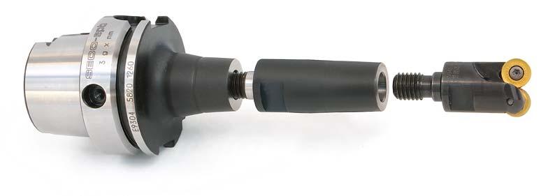
196 EPB - Combimaster 196
197 EPB - Combimaster arbors Types Arbors HSK-A Design 1 (5820) Design 2 (5821) HSK-A/ ISO A D a = D u Page 1 of 2 Taper HSK-A40 HSK-A50 HSK-A63 Combimaster bore size Part No. A L l 1 l a D a l u D u M D 5t β Design Balancing M10 E , ,5 6, ,26 M10 E , , ,5 3, ,34 M8 E , ,7 8 13,5 5, ,42 M8 E ,7 8 13,5 3, ,49 M8 E , ,7 8 13, ,54 M10 E , ,5 6, ,45 M10 E , , ,5 3, ,52 M10 E , , ,5 2, ,94 M12 E , , , ,52 M12 E , ,60 M12 E , , ,08 M16 E , , , ,54 M16 E , ,67 M16 E , , , ,12 M8 E , ,7 8 13,5 5, ,69 M8 E ,7 8 13,5 3, ,75 M8 E , ,7 8 13, ,83 M8 E , ,5 8 13, ,65 M10 E , ,5 6, ,72 M10 E , , ,5 3, ,75 M10 E , , ,5 2, ,97 M10 E , ,5 3, ,39 M10 E , , , ,67 M12 E , , , ,77 M12 E , ,87 M12 E , , , ,99 M12 E , , ,12 M12 E , , , ,66 M12 E , , ,70 M12 E , , ,80 M16 E , , , ,93 M16 E , ,00 M16 E , , , ,19 M16 E , , ,39 M16 E , , ,11 M16 E , , ,79 M16 E , , ,93 M16 E , , ,12 M16 E , , ,32 197
198 EPB - Combimaster arbors Types Arbors HSK-A Design 1 (5820) Design 2 (5821) HSK-A/ ISO A D a = D u Page 2 of 2 Taper HSK-A80 HSK-A100 Combimaster bore size Part No. A L l 1 l a D a l u D u M D 5t β Design Balancing M8 E , ,7 8 13,5 7, ,22 M8 E , ,7 8 13,5 6, ,36 M10 E , ,5 7, ,15 M10 E , , ,5 6, ,41 M10 E , , ,5 5, ,68 M12 E , , ,40 M12 E , , ,54 M12 E , , ,80 M12 E , , , ,32 M16 E , , , ,52 M16 E , , ,75 M16 E , ,12 M16 E , , ,59 M8 E , ,7 8 13,5 7, ,12 M10 E , ,5 7, ,18 M10 E , , ,5 6, ,32 M12 E , , ,26 M12 E , , ,40 M12 E , , ,66 M12 E , , , ,00 M16 E , , , ,45 M16 E , ,93 M16 E , , ,41 M16 E , ,23 198
199 EPB - Combimaster arbors Type Arbors HSK-E HSK-E Taper HSK-E32 HSK-E40 HSK-E50 Combimaster bore size Part No. A L l 1 l a D a l u D u M D 5t β Balancing M8 E , ,7 8 13,5 5,3 1 0,18 M8 E ,7 8 13,5 3,5 1 0,26 M8 E , ,7 8 13, ,38 M8 E , ,7 8 13,5 5,3 1 0,23 M8 E ,7 8 13,5 3,5 1 0,31 M8 E , ,7 8 13, ,43 M10 E , ,5 6,3 1 0,26 M10 E , , ,5 3,9 1 0,34 M10 E , ,5 3,3 1 0,46 M8 E , ,7 8 13,5 5,3 1 0,42 M8 E ,7 8 13,5 3,5 1 0,49 M10 E , ,5 6,3 1 0,45 M10 E , , ,5 3,9 1 0,52 M10 E , ,5 3,3 1 0,73 M12 E , , ,2 1 0,52 M12 E , ,60 M16 E , , ,2 1 0,54 M16 E , ,67 199
200 EPB - Combimaster arbors Types Arbors DIN DIN ADB/ CAT Combined Design 1 (5820) Design 2 (5821) D a = D u Taper Combimaster bore size Part No. A L l 1 l a D a l u D u M D 5t β Design Balancing DIN40 ADB/ CAT40 M8 E , , ,7 8 13,5 5, ,01 M8 E , ,7 8 13,5 3, ,05 M8 E , , ,7 8 13, ,11 M8 E , , ,5 8 13, ,92 M10 E , ,7 5 19, , ,96 M10 E , , ,5 6, ,00 M10 E , , , ,5 3, ,08 M10 E , , , ,5 2, ,20 M10 E , , ,5 3, ,32 M10 E , , , , ,96 M12 E , ,7 5 24, ,96 M12 E , , , , ,02 M12 E , , ,12 M12 E , , , , ,22 M12 E , , , ,34 M12 E , , , , ,58 M12 E , , , ,98 M12 E , , , ,05 M16 E , ,7 5 31, ,94 M16 E , , , , ,19 M16 E , , ,24 M16 E , , , , ,42 M16 E , , , , ,62 M16 E , , , , ,06 M16 E , , , ,18 M16 E , , , ,38 M16 E , , , ,56 DIN50 ADB/ CAT50 M12 E , , , ,26 M12 E , , , ,58 M12 E , , , , ,78 M12 E , , , , ,98 M16 E , , , , ,38 M16 E , , ,84 M16 E , , , ,32 M16 E , , ,90 M16 E , , , , ,98 200
201 EPB - Combimaster arbors Types Arbors BT JIS Design 1 (5820) Design 2 (5821) BT JIS B 6339-ADB D a = D u Taper BT40 ADB BT50 ADB Combimaster bore size Part No. A L l 1 l a D a l u D u M D 5t β Design Balancing M8 E , , ,7 8 13,5 5, ,02 M8 E , ,7 8 13,5 3, ,07 M8 E , , ,7 8 13, ,14 M8 E , , ,5 8 13, ,94 M10 E , ,7 5 19, , ,96 M10 E , , ,5 6, ,04 M10 E , , , ,5 3, ,10 M10 E , , , ,5 2, ,22 M10 E , , ,5 3, ,34 M10 E , , , , ,98 M12 E , ,7 5 24, ,98 M12 E , , , , ,06 M12 E , , ,16 M12 E , , , , ,26 M12 E , , , ,38 M12 E , , , ,00 M12 E , , , ,08 M16 E , ,7 5 31, ,18 M16 E , , , , ,23 M16 E , , ,30 M16 E , , , , ,46 M16 E , , , , ,68 M16 E , , , ,12 M12 E , , , ,76 M12 E , , , ,08 M12 E , , , , ,28 M12 E , , , , ,48 M16 E , , , , ,88 M16 E , , ,34 M16 E , , , ,98 M16 E , , ,42 M16 E , , , , ,11 201
202 EPB - Combimaster intermediates Types BS/ Extensions Combimaster shank size Combimaster bore size Part No. A M 2 M 1 D 5m D 5t Balancing M8 M8 BS ,5 13,5 2 0,03 M10 M10 BS ,5 18,5 2 0,06 M12 M12 BS ,12 M16 M16 BS ,20 202
203 EPB - Combimaster intermediates Types BS/ Reducers Combimaster shank size Combimaster bore size Part No. A l 1 D a l u D u M 2 M 1 D 5m D 5t β Balancing M10 M8 BS ,5 8 15, ,5 13,5 8,8 2 0,06 M12 M10 BS , ,5 5,9 2 0,10 M16 M10 BS , ,5 7,15 2 0,24 M16 M12 BS , ,2 2 0,19 203
204 EPB - Combimaster intermediates Types BD/ Cylindrical extensions, steel, heavy metal or carbide Design 1 (5820) Design 2 (5821) Design 3 (5822) D a = D 5t Combimaster bore Cyl. Shank D m Size Part No. A L l a D a l u D u M D 5t β Design Balancing 14 M8 BD , ,12 14 M8 BD E , ,30 16 M8 BD , ,17 16 M8 BD E , ,44 18 M10 BD ,22 18 M10 BD E ,63 20 M10 BD , ,27 20 M10 BD D , , ,43 20 M10 BD , , ,32 20 M10 BD D , , ,73 25 M12 BD ,48 25 M12 BD E ,65 25 M12 BD ,89 25 M12 BD D ,00 32 M12 BD , , ,86 32 M12 BD D , , ,90 32 M12 BD , , ,50 32 M12 BD D , , ,50 32 M16 BD ,93 32 M16 BD ,89 32 M16 BD D ,90 32 M16 BD D ,50 32 M16 BD ,65 32 M16 BD D ,70 40 M16 BD , , ,40 40 M16 BD , , ,75 40 M16 BD , , ,58 40 M16 BD D , , ,80 D = heavy metal, E = carbide. 204
205 EPB - Combimaster intermediates Type BW/ Weldon extensions Design 1 (5820) Design 2 (5821) DIN Form B D a = D u Weldon Shank D m Combimaster bore size Part No. A L l a D a l u D u M D 5t β Design Balancing 20 M10 BW , , , ,17 20 M10 BW , , , ,33 25 M12 BW , , ,36 25 M12 BW , , ,60 32 M12 BW , , ,87 32 M16 BW , , ,58 205
206 EPB - Combimaster intermediates Types BC/ Morse Taper extensions Design 1 (5820) Design 2 (5821) DIN 228 Form A D a = D u = D 5t l u = l a Morse Taper size T Combimaster bore size Part No. A L l a D a l u T D u M D 5t β Design Balancing 2 M10 BC , ,780 18, , ,13 2 M10 BC , ,780 18, , ,20 3 M10 BC ,825 19, ,5 1, ,43 3 M10 BC ,825 19, ,5 1, ,45 3 M10 BC D ,825 19, ,5 1, ,00 3 M12 BC , ,27 3 M12 BC , ,35 3 M12 BC , ,43 3 M16 BC , ,26 3 M16 BC , ,40 4 M12 BC , , ,267 24, , ,95 4 M12 BC D , , ,267 24, , ,10 4 M16 BC ,5 53, ,5 31, ,76 4 M16 BC ,5 93, ,5 31, ,98 4 M16 BC D ,5 93, ,5 31, ,20 206
207 EPB - Combimaster adapters Type BM/ Graflex Combimaster adapters Graflex shank d Combimaster bore Size mm size Part No. A l 1 D l a D a l u D u M D 5t β Balancing BM ,7 8 13, , BM , , ,5 15,6 2 0, BM , ,25 2 0, BM , ,25 2 0,61 207
208 EPB - Combimaster adapters Type BS/ Combimaster Shrinkfit adapters Combimaster shank size Shrinkfit d mm Part No. A l 1 l 3 l 4 D D 3 D 5m M T A 1 min-max Balancing 12 6 BS M , BS M , BS M , BS M , BS M , BS M ,34 Accessories Stop end screw For Size/ d S 1 M12/6-8 19LS0520A 3 3 M16/6 19LS0520A 3 3 M16/ LS0620A 3 3 For stop screw setting adapters, see chapter Shrinkfit devices. 208

209 EPB - Graflex 209
210 EPB - Graflex arbors Type EM - Arbors HSK-A HSK-A/ ISO A Graflex bore Taper HSK-A32 HSK-A40 HSK-A50 HSK-A63 HSK-A80 HSK-A100 Size d 1 Part No. A L l 1 D 1 Balancing 2 14 EM , EM , EM , EM , EM , EM , EM , EM , EM , EM , EM , EM , EM , EM , EM , EM , EM , EM , EM , EM , EM , EM , EM , EM , EM , EM ,00 For HSK-A sealing plugs, coolant tubes and tube spanners, see chapter Additional equipment. 210
211 EPB - Graflex arbors Type EM - Arbors HSK-E Design 1 Design 2 HSK-E Particularly suitable to run NanoBore head on small HSK-E spindles. Graflex bore Taper HSK-E25 HSK-E32 HSK-E40 Size d 1 Part No. A l 1 l 2 D 1 D 2 L Design Balancing 2 14 EM , EM , EM ,20 211
212 EPB - Graflex arbors Type EM - Arbors DIN AD Design 1 Design 2 DIN AD Graflex bore Taper DIN30 AD DIN45 AD Size d 1 mm Part No. A l 1 l 2 D 1 D 2 L Design Balancing 2 14 EM , , , EM , , , EM , , , EM , , , EM , , , EM , , ,10 212
213 EPB - Graflex arbors Type EM - Arbors DIN ADB Design 1 Design 2 DIN ADB Graflex bore Taper DIN40 ADB DIN50 ADB Size d 1 mm Part No. A l 1 l 2 D 1 D 2 L Design Balancing 1 11 EM , , , EM , , , EM , , , EM , , , EM , , , EM , , , EM , , , EM , , , EM , , , EM , , , EM , , , EM , , , EM , , , EM , , , EM , , , EM , , , EM , , , EM , , , EM , , , EM , , , EM , , , EM , , , EM , , , EM , , , EM , , , EM , , ,50 213
214 EPB - Graflex arbors Type EM - Arbors DIN-AD/ CAT Metric Combined DIN AD/ CAT Metric Compatible Design 1 Design 2 Graflex bore Taper Size d 1 mm Part No. A l 1 l 2 D 1 D 2 L Design Balancing DIN40 AD/ CAT EM , ,45 103, , EM , ,45 103, , EM , ,45 108, , EM , ,45 148, , EM , ,45 188, , EM , ,45 128, ,40 DIN50 AD/ CAT EM , ,85 141, , EM , ,85 201, , EM , ,85 241, , EM , ,85 146, , EM , ,85 201, , EM , ,85 241, , EM , ,85 166, , EM , ,85 221, ,50 214
215 EPB - Graflex arbors Type EM - Arbors BT JIS-AD Design 1 Design 2 BT JIS B 6339-AD Graflex bore Taper BT30 AD Size d 1 mm Part No. A l 1 D 1 D 2 L Design Balancing 2 14 EM , , EM , , EM , , EM , ,65 215
216 EPB - Graflex arbors Type EM - Arbors BT JIS-ADB Design 1 Design 2 BT JIS B 6339-ADB Graflex bore Taper BT40 ADB BT50 ADB Size d 1 mm Part No. A l 1 D 1 D 2 L Design Balancing 1 11 EM , , EM , , EM , , EM , , EM , , EM , , EM , , EM , , EM , , EM , , EM , , EM , , EM , , EM , , EM , , EM , , EM , , EM , , EM , , EM , , EM , , EM , , EM , , EM , , EM , , EM , ,75 216
217 EPB - Graflex arbors Type EM - Arbors DIN 2080 DIN 2080 Design 1 Design 2 Graflex bore Taper DIN(2080)40 DIN(2080)50 Size d 1 mm Part No. A l 1 D 1 D 2 L Design Balancing 3 18 EM , , , EM , , , EM , , , EM , , , EM , , EM , , , EM , , , EM , , , EM , , , EM , , , EM , , , EM , , , EM , , , EM , , , EM , , ,60 217
218 EPB - Graflex arbors Type ER - Adjustable arbors DIN AD and BT JIS B 6339-AD Enable radial and angular adjustment. Graflex bore Taper DIN40 AD DIN50 AD BT40 AD BT50 AD Size d 1 mm Part No. A l 1 D 1 D 2 Balancing 5 28 ER , ER , ER , ER ,50 218
219 EPB - Graflex arbors Type M409 - Flange mounts DIN 2079 Suitable for mounting on DIN 2079 type spindle front ends. Spindle size SA30 SA40 SA50 Graflex bore Size d 1 mm Part No. D 3 A l 1 D 1 D 2 Balancing 3 18 M , , M , , M , , M , , M , ,50 219
220 EPB - Graflex arbors Type VDI - Arbors VDI VDI DIN VDI back-end VDI16 VDI20 VDI30 VDI40 VDI50 Graflex bore Size d 1 mm Part No. A l 3 D 1 d 6 h 1 Balancing 3 18 VDI , VDI , VDI , VDI , VDI , VDI ,5 1, VDI ,5 1, VDI ,5 1, VDI , VDI , VDI ,90 220
221 EPB - Graflex intermediates Type M402 - Extensions Graflex shank Graflex bore Size d Size d 1 Part No. A D Balancing M , M , M , M , M , M , M , M , M , M , M , M , M , M , M , M , M , M , M ,80 221
222 EPB - Graflex intermediates Type M402 - Extensions, with reduced outer diameter Suitable for long wall milling and plunging. Graflex shank Size d mm Graflex bore Size d 1 mm Part No. A l 1 D D 1 Balancing M R , M R , M R ,30 222
223 EPB - Graflex intermediates Type M403 - Reducers Graflex shank Size d mm Graflex bore Size d 1 mm Part No. A l 1 D D 1 Balancing M , M , M , M , M , M , M , M , M , M , M , M , M , M , M , M , M , M , M , M , M , M , M ,35 223
224 EPB - Graflex intermediates Type M403 - Long reducers For extra long reducers, see following page. Graflex shank Size d mm Graflex bore Size d 1 mm Part No. A l 1 D D 1 Balancing M , M , M , M , M , M , M , M , M , M , M ,60 224
225 EPB - Graflex intermediates Type M403 - Extra long reducers, carbide The extension section is manufactured from carbide. Suitable for fine boring length up to 'l u '. Graflex shank Size d mm Graflex bore Size d 1 mm Capacity heads C mm Part No. A l 1 l 2 D 2 D D 1 l u Balancing ,5 M403 50C , M403 51C , M403 52C , M403 61C , M403 63C ,90 225
226 EPB - Graflex intermediates Type M403 - Enlargers Graflex shank Size d mm Graflex bore Size d 1 mm Part No. A D D 1 Balancing M , M ,80 226
227 EPB - Graflex intermediates Type M401 - Cylindrical extensions, steel Suitable for boring length up to 'l u '. Cylindrical shank d h6 with tolerance h6, with flat. Shank d h6 Graflex bore Size d 1 mm Capacity heads C mm Part No. L L 1 D 1 l u Balancing ,5 M , ,5 M , M , M , M ,90 227
228 EPB - Graflex intermediates Type M401 - Cylindrical extensions, carbide Suitable for fine boring length up to 'l u '. Cylindrical shank d h5 with tolerance h5, compatible for Shrinkfit. Shank d h5 Graflex bore Size d 1 mm Capacity heads C mm Part No. L L 1 D 1 l u Balancing ,5 M C , ,5 M C , M C , M C , M C ,50 228
229 EPB - Graflex tool holders Type M5525/ Shell mill holders, with through coolant channels Design 1 Design 2 With coolant supply channels through the spigot. Graflex shank Size d d 1 Graflex mm mm Part No. A l 2 α l 3 D Front D 1 Design * Balancing M * 2 0, M R (R) , M * 2 0, M , M * 2 1, M R (R) 48 1 * 2 0, M ** 2 * 2 0, M R (R) 48** 1 * 2 0, M , , M , M R (R) 60 1 * 2 1, M R (R) 60 1 * 2 3, M * 2 1, M R (R) , M , M R (R) 78 1 * 2 2,25 * Suitable for long wall milling and plunging. (R) = D reduced compared to the standard Graflex D. **Diameter D 1 on type 5524 is smaller than on type Accessories Spanner for bolt Bolt, through coolant type (4) Spare parts Bolt (1) Tenon/ Screw for tenon (2) For d 1 /shank 16/ L C D /4, 16/ L C D /4, 22/5, 22/ L C D /5/ L C D /5/ L C D /6, 27/ L C D /6, 32/ L C D
230 EPB - Graflex tool holders Type M553 - Combi shell mill holders DIN 6358 With removable driving ring. Graflex shank Size d mm d 1 mm Part No. A A 1 l 3 l 4 D D 1 Balancing M , M , M , M , M , M ,52 Accessories Spanner for bolt Bolt, through coolant type (4) Spare parts Bolt (1) Driving ring (2) Flat key (3) For d L C L C L C L C
231 EPB - Graflex tool holders Type M569 - Milling cutter holders, flange mounting DIN 6357/ DIN 2079 Graflex shank Size d mm d 1 mm Part No. A l 3 D D 1 f M Balancing M ,7 M12 2 3, M ,6 M16 2 6,40 d 1 40, with additional central thread and bolt according to ISO Accessories Spare parts Spanner for bolt Tenon (2) Bolt (1) For d C C
232 EPB - Graflex tool holders Type M Disc mill holders With adjustable sliding shaft arbor. Graflex shank Size d mm d 1 mm Part No. A l 1 l 3 D D 1 Balancing M , M , M , M , M , M , M , M , M ,90 Spare parts Shaft arbor with key (1) Screw (2) For S M D M D M D M D M D M D M D M D M D
233 EPB - Graflex tool holders Type M584 - Side lock holders, Weldon DIN 1835 Form B/ DIN 6535 Form HB Design 1 Design 2 Weldon d 16, 20, 25, 32 and 40 with ground face (Seco-Weldon compatible). Graflex shank Size d mm d 1 mm Part No. A l 1 l 3 D D 1 A 1 Design Balancing M , M , M , M , , M , , M , M , M , M , M , M , M , , M , , M , M , M , M , M ,30 Spare parts Locking screw (1) Locking screw (2) For d 1 S S 6 951C C C C C C C C C C
234 EPB - Graflex tool holders Type M584 - Side lock holders, Weldon DIN 1835 Form B/ DIN 6535 Form HB Weldon d 16, 20, 25, 32 and 40 with ground face (Seco-Weldon compatible). Graflex shank Size d mm d 1 mm Part No. A l 1 l 3 D D 1 A 1 Design Balancing M , M ,80 Spare parts Locking screw (1) For d 1 Qty S C C
235 EPB - Graflex tool holders Type M Side lock holders, Whistle Notch DIN 1835 Form E/ DIN 6535 Form HE Design 1 Design 2 Whistle Notch d 16, 20, 25 and 32 with ground face. Graflex shank Size d mm d 1 mm Part No. A l 1 l 3 D D 1 A 1 min-max Design Balancing M , M , M , M , M , M , M , M , M , M , M , M , M , M , M , M , M ,30 Spare parts Locking screw (1) Locking screw (2) Stop end screw (5) For d 1 S S S 6 951C L C L C TLR C TLR C TLR C TLR C C TLR C C TLR
236 EPB - Graflex tool holders Type BM Shrinkfit holders, DIN type Graflex shank Size d Part No. A A 1 l 1 l 3 l 4 D D 1 D 3 M d 1 Balancing BM M8 2 0, BM M8 2 0, BM M8 2 0, BM M10 2 0, BM M10 2 1, BM M10 2 1, BM M10 2 1, BM M10 2 1, BM M10 2 1, BM M10 2 1, BM M10 2 1, BM M10 2 1, BM M10 2 1, BM M10 2 2, BM M10 2 2,10 For Shrinkfit extensions, see chapter Additional equipment. Accessories Stop end screw For d 1 S LS0820T LS0820A LS1020A 5 5 For stop screw setting adapters, see chapter Shrinkfit devices. 236
237 EPB - Graflex tool holders Type M D type precision collet chucks Graflex shank D Size d mm type size Capacity mm Part No. A l 1 l 2 D D 1 D 2 M Balancing 5 28 D M , M8 2 0, D M , M8 2 0, D M , M12 2 1,25 For D type collets (10 taper), see pages Accessories Spare parts Compression ring Sealing nut (4) Sealing ring (3) Nut (1) For D type size L 1 S L 1 S D 16 03D587216A 08B587216BE B * 08B D 24 03D587224A 08B587224BE B * 08B D 29 03D587229A 08B587229BE B * 08B *For D type sealing rings, see page
238 EPB - Graflex tool holders Type M Hydraulic chucks Graflex shank Max Size d mm d 1 mm Part No. transmis. torque N.m A l 2 l 4 D D 1 D 2 M A 1 min-max Balancing M M , M M ,30 For reduction sleeves, see page 303 and control gauges, see page 304. Accessories Spare parts Key for pressurizing (S 2 ) Stop end screw (1) Pressurizing screw (2) For d 1 S 2 S 1 S 20 H LS1020A AF H LS1020A AF
239 EPB - Graflex tool holders Type M ER collet chucks DIN 6499 Graflex shank Size d Capacity K mm Size mm Part No. A l 1 D D 1 D 2 d 2 min-max Balancing 3 18 ER M R , , ER M M , ER M M , ER M M , ER M M , ER M M ,80 For ER collets (16 taper, standard and precision types), see pages ER extensions, see page 305. Accessories Spare parts Spanner Sealing nut (4) Sealing ring (3) Nut (1) Stop end screw (2) For d/size L 1 L 1 S 18/ ER 25 03B B587525M 20 19PM / ER 25 03B B587525IC 25 01B * 08B587525X 21 19PM / ER 32 03B B587532IC 27,5 01B * 08B587532X 23 19PM / ER 25 03B B587525IC 25 01B * 08B587525X 21 19PM / ER 32 03B B587532IC 27,5 01B * 08B587532X 23 19PM / ER 40 03B B587540IC 30,5 01B * 08B587540X 26 19PM * For ER type sealing rings, see page

240 EPB - Graflex tool holders Type M OZ collet chucks DIN 6388 Graflex shank Size d Capacity K mm Size mm Part No. A l 1 D D 1 D 2 d 2 min-max Balancing 5 28 OZ M M , OZ M M , OZ M M12 65-/ 2 2,00 For OZ collets (1/10 taper), see pages Accessories Spare parts Spanner Nut (1) Stop end screw (2) For Size L 1 S OZ 25 03B B PM OZ 32 03B B ,5 19PM
241 EPB - Graflex tool holders Type M Universal drill chucks Graflex shank Size d mm Capacity d 1 mm Part No. A l 1 D D 1 Balancing M L , ,5-16 M L ,50 Accessories Locking key For d S 28 H H
242 EPB - Graflex tool holders Type M536 - Holders for Morse Taper with tang DIN Form D Designed to fit a pull-back screw and a pull-back sleeve shown in Accessories. Graflex shank d Size mm MT Part No. A l 1 D D 1 Balancing M , M , M , M , M , M , M , M , M ,45 For Morse Taper reducers, see chapter Additional equipment. Accessories Pull-back screw Pull-back sleeve For d/mt S 28/1 950D /2 950D /3 950D B /4 950D B /1 950D /2 950D /3 950D /4 950D B /5 950D B
243 EPB - Graflex tool holders Type M536 - Holders for Morse Taper with tang, for through coolant With a securing screw (1) and an ejecting screw (2). Graflex shank d Size mm MT Part No. A l 1 D D 1 Balancing M L , M L , M L , M L ,15 For Morse Taper reducers, see chapter Additional equipment. Spare parts Screw (1) Screw (2) For d/mt S S 36/1 950A L /2 950A L /3 950A L /4 950A L
244 EPB - Graflex tool holders Type M533 - Holders for Morse Taper with thread DIN 6364 Form B/ DIN Form C Design 1 Design 2 Graflex shank d Size mm MT Part No. A l 1 D D 1 Design Balancing M , M , M , M , M , M ,00 Spare parts Screw (1) Ring (2) Ball (3) Screw (4) Screw (5) For d/mt S Qty 28/2 950D /3 950D B B A T /2 950D /3 950D B B A T /4 19B B B A T /4 19B B B A T
245 EPB - Graflex tool holders Type M Quick change tapping chucks with axial compensation With extension and compression. Without through coolant (for through coolant, see following page). Graflex shank Size d mm For tap adapter Size d 1 Tapping mm range Part No. Compression Extension A D D 1 Balancing M3-M12 M ,5 7, , M3-M12 M ,5 7, , M3-M12 M ,5 7, , M8-M20 M ,5 12, , M14-M33 M ,00 For quick change tap adapters, see chapter Additional equipment. 245
246 EPB - Graflex tool holders Type M Quick change tapping chucks with axial compensation, for through coolant With extension and compression. Maximum coolant pressure 15 bar. Graflex shank Size d mm For tap adapter Size d 1 Tapping mm range Part No. Compression Extension A D D 1 Balancing M3-M12 M L 7,5 7, , M3-M12 M L 7,5 7, , M3-M12 M L 7,5 7, , M8-M20 M L 12,5 12, , M14-M33 M L ,00 For quick change tap adapters, see chapter Additional equipment. 246
247 EPB - Graflex tool holders Type M Quick change tapping chucks for synchronized tapping No compensation. Maximum coolant pressure 50 bar. Graflex shank Size d mm For tap adapter Size d 1 mm Tapping range Part No. A D D 1 Balancing M3-M12 M , M8-M20 M , M14-M34 M ,90 247
248 EPB - Graflex tool holders Type M ER tapping chucks for synchronized tapping DIN 6499 No compensation. Graflex shank Size d mm Size Tapping range Capacity d 1 mm Part No. A l 2 A 1 D D 1 D 2 Balancing 5 28 ER 25 M5-M M , ER 32 M5-M M , , ER 40 M12-M M , ,10 For ER collets (16 taper, standard and precision types), see pages Accessories Spare parts Spanner Sealing nut (4) Sealing ring (3) Nut (1) Driving system (5) For Size L 1 L 1 S ER 25 03B B587525IC 25 01B * 08B587525X 21 90T ER 32 03B B587532IC 27,5 01B * 08B587532X 23 90T ER 40 03B B587540IC 30,5 01B * 08B587540X 26 90T *For ER type sealing rings, see page
249 EPB - Graflex tool holders Type M Greenstock blanks Graflex shank d Size mm Part No. A l 1 D D 1 Balancing 4 22 M , M , M , M ,50 249
250 EPB - Graflex tool holders Type BM/ Adjustable drill holders, for type 7 drill shanks For Perfomax drills. Adjustable from -0,3 mm to +0,8 mm on diameter. Graflex shank Size d mm For drill shank type d 1 mm d 1 inch Part No. L D d 2 l 3 Balancing mm-version BM , BM , BM ,60 inch-version BM , ,25 BM , ,5 BM ,70 Accessories Spare parts Reducing sleeve Locking key Locking screw (1) For d 1 mm/inch D d S S mm-version 25 H AF B H AF B H AF B H AF inch-version 1,0 H AF ,25 05B ,25 1,0 H AF ,5 05B ,5 1,0 H AF ,5 05B ,5 1,25 H AF
251 EPB - Graflex tool holders Type BSM/ /A0 - Rotary coolant inducers, automatic tool change, for type 7 drill shanks, adjustable ISO 9766 For Perfomax drills. Adjustable from -0,3 mm to +0,8 mm on diameter. Filtration to 40 µm maximum required. * Stroke Graflex shank For drill Size d 5m mm shank type d 1 mm d 1 inch Part No. L B D 2 d 2 L 1 l 3 Max pressure in bar Max rpm Balancing mm-version BSM A , , BSM A , , BSM A , , BSM A , , BSM A , , BSM A , ,5 inch-version ,0 BSM A , , ,25 BSM A , , ,5 BSM A , , ,0 BSM A , , ,25 BSM A , , ,5 BSM A , ,5 Accessories Spare parts Socket Reducing sleeve Locking key Locking screw (1) Plug (2) For d 1 mm/inch D d S S mm-version 25 E99000 H AF A E B H AF A E B H AF A E B H AF A1012 inch-version 1,0 E99000 H AF A1012 1,25 E B ,25 1,00 H AF A1012 1,5 E B ,50 1,00 H AF A1012 1,5 E B ,50 1,25 H AF A
252 EPB - Graflex tool holders Type BSM/ /00 - Rotary coolant inducers, manual tool change, for type 7 drill shanks, adjustable For Perfomax drills. Adjustable from -0,3 mm to +0,8 mm on diameter. Filtration to 40 µm maximum required. Graflex shank For drill Size d 5m mm shank type d 1 mm d 1 inch Part No. L D 2 d 2 l 3 Max pressure bar Max rpm Balancing mm-version BSM , BSM , BSM ,0 inch-version ,0 BSM , ,25 BSM , ,5 BSM ,0 Accessories Spare parts Reducing sleeve Locking key Locking screw (1) Plug (2) For d 1 mm/inch D d S S mm-version 25 H AF A B H AF A B H AF A B H AF A1012 inch-version 1,0 H AF A1012 1,25 05B ,25 1,0 H AF A1012 1,5 05B ,5 1,0 H AF A1012 1,5 05B ,5 1,25 H AF A
253 EPB - Graflex tool holders Type BSM/ /A0 - Rotary coolant inducers, automatic tool change, for type 7 drill shanks ISO 9766 Filtration to 40 µm maximum required. Graflex shank For drill Size d 5m mm shank type d 1 mm d 1 inch Part No. L B D 2 d 2 L 1 l 3 Max pressure bar Max rpm Balancing mm-version BSM A , , , BSM A , , , BSM A , , BSM A , , BSM A , , BSM A , ,5 inch-version ,0 BSM A0 105,4 112, , , , ,0 BSM A0 105,4 127, , , , ,25 BSM A0 110,5 127, , , ,25 BSM A0 110,5 142, , , ,5 BSM A0 115,5 127, , , ,5 BSM A0 115,5 142, , ,5 Accessories Spare parts Socket Reducing sleeve Locking key Locking screw (1) Plug (2) For d 1 mm/inch D d S S mm-version 25 E99000 H X A E B H X A E B H X A E B H X A1012 inch-version 1,0 E99000 H X A0810 1,25 E B ,25 1,00 H X A1012 1,5 E B ,50 1,00 H X A1012 1,5 E B ,50 1,25 H X A
254 EPB - Graflex tool holders Type BSM/ /00 - Rotary coolant inducers, manual tool change, for type 7 drill shanks Filtration to 40 µm maximum required. Graflex shank For drill Size d 5m mm shank type d 1 mm d 1 inch Part No. L D 2 d 2 l 3 Max pressure bar Max rpm Balancing mm-version BSM , , BSM , BSM ,0 inch-version ,0 BSM , ,5 42, , ,25 BSM , , , ,5 BSM , , ,0 Accessories Spare parts Reducing sleeve Locking key Locking screw (1) Plug (2) For d 1 mm/inch D d S S mm-version 25 H X A B H X A B H X A B H X A1012 inch-version 1,0 H X A0810 1,25 05B ,25 1,00 H X A1012 1,5 05B ,50 1,00 H X A1012 1,5 05B ,50 1,25 H X A
255 EPB - Graflex tool holders Type BSM/ /A0 - Rotary coolant inducers, automatic tool change, for type 5 drill shanks Filtration to 40 µm maximum required. * Stroke Graflex shank For drill Size d 5m mm shank type d 1 mm d 1 inch Part No. L B D 2 d 2 L 1 l 3 Max pressure bar Max rpm Balancing mm-version BSM A , , BSM A , , BSM A , , BSM A , , BSM A , , , BSM A , , , BSM A , , BSM A , ,1 inch-version ,625 BSM A0 101,6 112, , , ,625 BSM A0 101,6 127, , , ,75 BSM A0 101,6 112, , , ,75 BSM A0 101,6 127, , , ,0 BSM A0 115,5 112, , , , ,0 BSM A0 115,5 127, , , , ,25 BSM A0 110,5 127, , , ,25 BSM A0 110,5 142, , ,1 Accessories Spare parts Socket Locking key Locking screw (1) Plug (2) For d 1 mm/inch S Qty S mm-version 16 E99000 H X A E99000 H X A E99000 H X A E99000 H X A1012 inch-version 0,625 E99000 H X A0810 0,75 E99000 H X A0810 1,0 E99000 H X A0810 1,25 E99000 H X A

256 EPB - Graflex tool holders Type BSM/ /00 - Rotary coolant inducers, manual tool change, for type 5 drill shanks Filtration to 40 µm maximum required. Graflex shank For drill Size d 5m mm shank type d 1 mm d 1 inch Part No. L D 2 d 2 l 3 Max pressure bar Max rpm Balancing mm-version BSM , BSM , BSM , , BSM ,6 inch-version ,625 BSM , , , ,75 BSM , , , ,0 BSM , ,5 52, , ,25 BSM , , ,6 Accessories Spare parts Locking key Locking screw (1) Plug (2) For d 1 mm/inch S Qty S mm-version 16 H X A H X A H X A H X A1012 inch-version 0,625 H X A0810 0,75 H X A0810 1,0 H X A0810 1,25 H X A
257 EPB - Graflex tool holders Type BSM/5872/A0 - Rotary coolant inducers, automatic tool change, D type precision collet chuck Filtration to 40 µm maximum required. * Stroke Graflex shank Size d 5m mm D type size d 1 mm Part No. L B D 2 d 2 L 1 l 3 Max pressure bar Max rpm Balancing 5 28 D BSM A0 106,3 112, , , D BSM A0 106,3 127, , ,4 For D type collets (10 taper), see pages Accessories Spare parts Socket Compression ring Sealing ring (3) Sealing nut (4) Plug (2) For d 1 L 1 S 1-20 E D587229A 01B * 08B587229BE A0810 *For D type sealing rings, see page
258 EPB - Graflex tool holders Type BSM/5872/00 - Rotary coolant inducers, manual tool change, D type precision collet chuck Filtration to 40 µm maximum required. Graflex shank Size d 5m mm D type size d 1 mm Part No. L D 2 d 2 l 3 Max pressure bar Max rpm Balancing 5 28 D BSM , , ,8 For D type collets (10 taper), see pages Accessories Spare parts Compression ring Sealing ring (3) Sealing nut (4) Plug (2) For d 1 L 1 S D587229A 01B * 08B587229BE A0810 *For D type sealing rings, see page

259 EPB - Graflex tool holders Type BSM/401/A0 - Rotary coolant inducers, automatic tool change, for Graflex modules Filtration to 40 µm maximulm required. Graflex shank Graflex bore Size d 5m mm Size d 1 mm Part No. L l 3 B D 1 D 2 L 1 Max rpm Balancing BSM A , , BSM A , , BSM A , , BSM A , ,50 Accessories Spare parts Socket Plug (2) For d 5m 36 E A
260 EPB - Graflex tool holders Type BSM/401/00 - Rotary coolant inducers, manual tool change, for Graflex modules Filtration to 40 µm maximum required. Graflex shank Graflex bore Size d 5m mm Size d 1 mm Part No. L l 3 D 2 D 1 Max rpm Balancing BSM , BSM ,00 Spare parts Plug (2) For d 5m A
261 EPB - Graflex rough boring heads Type A750 - Rough boring heads Symmetrical and staggered boring is possible. Graflex shank Size Simultaneous adjustment mode Independent adjustment mode d Capacity C mm mm Part No. Yes No Yes No A D Balancing A [ [ 35 16,5 2 0, A [ [ 40 21,5 2 0, A [ [ , A [ [ , A [ [ , A [ [ , / A [ [ , / A [ [ ,680 Insert holders have to be ordered separately, see next pages. * Without insert holders. Accessories Spare parts Setting gauge Central screw (1) Key for (1) Key for (2) Torx driver for (3) Torx driver for (4) For Head S S T T A A HL03 3 H1.5-2D 1,5 T07P-3 T07P A75010 CAA A HL03 3 H1.5-2D 1,5 T06P-3 T06P T07P-3 T07P A75020 CAA A HL04 4 H2.0-2D 2 T07P-3 T07P T07P-3 T07P A75030 CAA A HL05 5 H2.0-2D 2 T08P-3 T08P T15P-3 T15P A75040 CAA A HL05 5 H2.5-2D 2,5 T09P-3 T09P T15P-3 T15P A75050 CAA A HL M03C 3 T15P-3 T15P T15P-3 T15P A75060 CAA A HL08 8 H T15P-3 T15P T15P-3 T15P A75070 CAA A HL10 10 H T15P-3 T15P T15P-3 T15P 261
262 EPB - Graflex rough boring heads Rough boring insert holders 90, for heads type A750 For fitting on to type A750 heads. Symmetrical boring requires two standard type A insert holders. Staggered boring requires one standard type A and one extended type B insert holders. Insert holders type For head Capacity mm Part No. Lead angle α Suitable insert size Standard type A A A750 00CP ,5 16,5 CP ,010 A A750 10CC ,5 21,5 CC ,018 A A750 20CC CC ,035 A A750 30CC CC...09T3... 0,080 A A750 40CC CC ,140 A A750 50CC CC ,250 A A750 60CC CC ,550 A A750 60CC CC ,550 A A750 65CC CC ,950 A A750 65CC CC ,950 A A750 70CC CC ,200 A A750 70CC CC ,200 A A750 75CC CC ,000 A A750 75CC CC ,000 Extended type B A A750 01CP ,8 16,5 CP ,010 A A750 11CC ,85 21,5 CC ,018 A A750 21CC ,35 27 CC ,035 A A750 31CC ,4 35 CC...09T3... 0,080 A A750 41CC ,5 43 CC ,140 A A750 51CC ,6 54 CC ,250 A A750 61CC ,6 70 CC ,550 A A750 61CC ,6 70 CC ,550 A A750 66CC ,6 100 CC ,950 A A750 66CC ,6 100 CC ,950 A A750 71CC ,6 95 CC ,200 A A750 71CC ,6 95 CC ,200 A A750 76CC ,6 141 CC ,000 A A750 76CC ,6 141 CC ,000 l 1 b For insert fixing spare screws and torx keys, see page Insert locking screws and keys. 262
263 EPB - Graflex rough boring heads Rough boring insert holders 80, for heads type A750 For fitting on to type A750 heads. Symmetrical boring requires two standard type A insert holders. Staggered boring requires one standard type A and one extended type B insert holders. Insert holders type For head Capacity mm Part No. Lead angle α Suitable insert size Standard type A A A750 00SC ,5 16,5 SC ,010 A A750 10SC ,5 21,5 SC ,018 A A750 20SC SC ,035 A A750 30SC SC...09T3... 0,080 A A750 40SC SC ,140 A A750 50SC SC ,250 A A750 60SC SC ,550 A A750 60SC SC ,550 A A750 65SC SC ,950 A A750 65SC SC ,950 A A750 70SC SC ,250 A A750 70SC SC ,250 A A750 75SC SC ,080 A A750 75SC SC ,080 Extended type B A A750 01SC ,2 16,5 SC ,010 A A750 11SC ,3 21,5 SC ,018 A A750 21SC ,9 27 SC ,035 A A750 31SC ,2 35 SC...09T3... 0,080 A A750 41SC ,4 43 SC ,140 A A750 51SC ,7 54 SC ,250 A A750 61SC ,8 70 SC ,550 A A750 61SC ,3 70 SC ,550 A A750 66SC ,8 100 SC ,950 A A750 66SC ,3 100 SC ,950 A A750 71SC ,8 95 SC ,250 A A750 71SC ,3 95 SC ,250 A A750 76SC ,8 141 SC ,080 A A750 76SC ,3 141 SC ,080 l 1 b For insert fixing spare screws and torx keys, see page Insert locking screws and keys. 263

264 EPB - Graflex chamfering rings Type A Chamfering rings One or two chamfering tools can be held. Min mm Capacity C mm Max α 15 Max α 30 Max α 45 Part No. Graflex external diameter D For square shank tools Size mm mm D 1 D 2 A l A ,5 0, A ,5 0, A ,5 0, A , A ,5 0, A ,5 1, A ,5 1, A ,5 3,00 Chamfering tools, square shank type, have to be ordered separately, see next page. Spare parts Back ring clamping screw (1) Adjusting screw (2) Tool locking screw (3) Front ring adjusting screw (4) Front ring locking screw (5) For D D A A A D D A A A D D A A A D D A A A D D A A A D D A A A D D A A A D
265 EPB - Graflex chamfering rings Chamfering tools, for rings type A5162 With square shank, for fitting on to type A5162 chamfering rings. Lead angle α Square shank mm Part No. L mm Suitable insert size 6 B06A-RER 32 * 0,01 8 B08B-RER 40 * 0,01 10 S10D-SVRBR11 60 VBMX ,04 12 S12E-SVRBR11 70 VBMX ,07 16 S16J-SVRBR VBMX ,20 6 B06A-TER 32 * 0,01 8 S08B-SVTBR11 40 VBMX ,02 10 S10D-SVTBR11 60 VBMX ,04 12 S12E-SVTBR11 70 VBMX ,07 16 S16J-SVTBR VBMX ,20 6 B06A-DER 32 * 0,01 8 S08B-SVDBR11 40 VBMX ,02 10 S10D-SVDBR11 60 VBMX ,04 12 S12E-SVDBR11 70 VBMX ,07 16 S16J-SVDBR VBMX ,20 * HSS square tool. For insert fixing spare screws and torx keys, see page Insert locking screws and keys. 265
266 EPB - Graflex fine boring heads A NanoBore fine boring head, axial type With micrometric adjusting (increment 0,01 mm and vernier 2,5 µm, on the diameter). Maximum operating speed is rpm or m/ min whichever is reached first without exceeding either of them. Graflex shank Size d Capacity C mm Part No. A D d 1 Max residual unbalance g.mm ,3-8 A ,10 For suitable boring tools with shanks 4 mm and 6 mm, see next page Fine boring tools, for NanoBore. * Without tool Accessories Magnifying glass Case Spare parts Reduction bushing (5) Tool fixing screw (2) Blocking screw (3) Key for (2) (3) (4) Torx driver for insert locking screw For d 1 d 2 S Torx. A L01 41B A A M4001A H2.0-2D 2 T06P-2 T06P 266
267 EPB - Graflex fine boring heads Fine boring tools, for NanoBore head A76001 Design 1 Design 2 Tool material Capacity C mm d 1 mm Part No. L l a f 1 r Lead angle Suitable insert size Recommended cutting data** Depth of cut (mm) Feed, f (mm/rev) Solid carbide* 0,3-0,6 4 A ,2 0,25 0, ,02 0,01 1 0,004 0,5-1,1 4 A ,45 0, ,02 0,01 1 0, ,1 4 A ,95 0,45 0, ,03 0,02 1 0, ,2 4 A ,80 0,88 0, ,05 0,02 1 0, ,7 4 A ,75 1,35 0, ,06 0,03 1 0,004 4,5-6,2 4 A ,95 1,95 0, ,08 0,03 1 0,005 Steel, indexable insert type A ,90 *** 90 WB *** *** 2 0,005 Design Carbide, indexable insert type A ,90 *** 90 WB *** *** 2 0,012 *Tools with shank dia 4 mm require the use of a reduction bushing, see NanoBore head and kits pages. **For cutting speed, see Guide pages 'Graflex modular system, NanoBore '. ***See inserts. Accessories Torx driver for insert locking screw* Spare parts Insert locking screw For insert size Torx. WB T06P-2 CO2035-T06P T06P * A torx driver is part of the NanoBore head and kits delivery content. 267
268 EPB Graflex fine boring heads NanoBore fine boring head kits case delivery content Delivery content Part No. Head Reduction bushing Tools Tools capacity mm Keys Magnifying glass NanoBore fine boring head Kit A (without tools) A76001A A A H2.0-2D 935L01 0,50 T06P-2 NanoBore fine boring head Kit B (with all tools) A76001B A A A ,3-0,6 H2.0-2D 935L01 0,60 A ,5-1,1 T06P-2 A ,1 A ,2 A ,7 A ,5-6,2 A A

269 EPB - Graflex fine boring heads A Fine boring head, axial type, slim With micrometric adjusting (increment 0,01 mm and vernier 2,5 µm, on the diameter). Graflex shank Graflex shank d Capacity C mm Part No. A D d 2 Balancing A , ,48 For suitable boring tools with shank 6 and 14, see page Fine boring tools. Spare parts Indexing screw (3) Reduction bushing (5) Tool fixing screw (6) Key for (4) (6) Blocking screw (8) * Without tool. Key for screw (8) For d 2 d 3 Qty S S A D0630L AU A H2.0-2D 2 950L M03C 3 A reduction bushing 14-6 mm is delivered with the head. 269
270 EPB - Graflex fine boring heads A Fine boring head, axial type With micrometric adjusting (increment 0,01 mm and vernier 2,5 µm, on the diameter). Graflex shank Size d mm Capacity C mm Part No. A D d 2 Balancing A ,30 For suitable reduction bushing ( 16-6 mm), see Accessories below. * Without tool. Accessories Spare parts Reduction bushing (5) Tool fixing screw (2) Blocking screw (3) Ring screw (6)** Key for (2) (3) (4) (6)** For d 2 d 3 S A78000/ A A A0812 AU AU H ** On head A79000 only. 270
271 EPB - Graflex fine boring heads A Libraflex balanceable fine boring head, axial type With micrometric adjusting (increment 0,01 mm and vernier 2,5 µm, on the diameter). Balancing by adjusting two rings to values on supplied chart. For speeds up to rpm. Graflex shank Size d mm Capacity C mm Part No. A D d 2 Max residual unbalance g.mm A ,25 For suitable reduction bushing 6 and 16 mm, see Accessories on page A * Without tool. Libraflex balanceable fine boring head kits - delivery contents Kit type Head Reduction bushing Qty. of carbide tools Qty. of steel tools Qty. of heavymetal tools Qty. of keys Part No. A A A A A A ( 6-32) 0 3 A A A ( 2-6) 7 ( 6-32) 4 ( 6-16) 3 For Accessories and Spare parts, see page A
272 EPB - Graflex fine boring heads Fine boring tools, for heads A72002, A78000 and A79000 Design 1 Design 2 Design 3 For fitting on to axial type Fine boring heads A72002, A78000 and A Tool material For head Capacity C mm d 1 mm Lead angle α Part No. Suitable insert size Solid carbide* A72002/ A78000/ A A ,01 A72002/ A78000/ A ,5 6 A ,015 A72002/ A78000/ A ,5-6 6 A ,015 Steel, indexable insert type Heavy metal, indexable insert type Steel, indexable insert type Heavy metal, indexable insert type Carbide, indexable insert type L l Design A A WB ,03 A A WB ,04 A A CC ,05 A A CC ,09 A A WB ,06 A A WB ,08 A A CC ,12 A78000/ A A WB ,04 A78000/ A A WB ,04 A78000/ A A CC ,05 A78000/ A A CC ,09 A78000/ A A CC ,11 A78000/ A A CC ,12 A78000/ A A CC ,12 A78000/ A A WB ,09 A78000/ A A WB ,10 A78000/ A A A 55 CC ,12 A78000/ A A B 70 CC ,18 A78000/ A A WB ,08 A78000/ A A WB ,10 A78000/ A A A 72 CC ,10 A78000/ A A B 92 CC ,16 A78000/ A , A A 112 CC ,18 * Tools with shank dia 6 mm require the use of a reducing bushing for fitting into the heads, see Head pages. For insert fixing spare screws and torx keys, see page insert locking screws and keys. 272
273 EPB - Graflex fine boring heads Type A780 - Fine boring heads, radial type With micrometric adjusting (increment 0,01 mm and vernier 2,5 µm, on the diameter). Graflex shank Size d mm Capacity C mm Part No. A D Insert holder size Balancing ,5 A , ,5 A , A , , A , A , A , A , / A / 65 3, / A / 75 6,360 Insert holders have to be ordered separately, see next pages. * Without insert holder. Spare parts Insert holder fixing screw (2) Blocking screw (3) Key for (2) (3) (4) For S A D30050S 19A H2.0-2D 2 A78009 LBHF0306R 19A71000 H2.0-2D 2 A TB A71000 H2.0-2D 2 A TB A0406 H2.0-2D 2 A TB L M03C 3 A TB L M03C 3 A D L M03C 3 A D L1016 H A D L1030 H
274 EPB - Graflex fine boring heads Type A790 - Libraflex balanceable fine boring heads, radial type With micrometric adjusting (increment 0,01 mm and vernier 2,5 µm, on the diameter). Balancing by setting both rings in accordance with the diameter to be bored. For speeds Vc up to m/min. Graflex shank Size d mm Capacity C mm Part No. A D Insert holder size Max residual unbalance g.mm A , A , A , A , A ,930 Insert holders have to be ordered separately, see next pages. * Without insert holder. Spare parts Insert holder fixing screw (2) Blocking screw (3) Ring screw (6) Key for (2) (3) (4) (6) For S A TB A D30045S H2.0-2D 2 A TB L0608 AU M03C 3 A TB L0612 AU M03C 3 A D L0616 AU M03C 3 A D L1016 AU H
275 EPB - Graflex fine boring heads Fine boring insert holders 90 and 95, for radial type heads type A780 and A790. Design 1 Design 2 Design 3 Design 4 For fitting on to type A780 and A790 radial heads. Lead angle α For A and A Insert holder size Capacity C mm Part No. l 1 f 1 Suitable insert size 90 for WB inserts...08 / ,5 A ,2 4 WB , for CC inserts A ,3 4,5 CC , A ,3 5 CC , A ,3 8 CC , A ,3 9,5 CC , A ,3 12,5 CC , * A ,5 18,9 CC...09T , ** * A ,5 33,7 CC...09T , A ,5 18,9 CC...09T , A ,5 41,7 CC...09T , for TC inserts A ,3 7,9 TC , A ,3 9,4 TC , A ,3 12,4 TC , * A ,3 18,9 TC , ** * A ,5 33,7 TC , A ,3 18,9 TC , A ,5 41,7 TC , for CC inserts A ,3 4,5 CC , A ,3 5 CC , A ,3 8 CC , A ,3 9,5 CC , A ,3 12,5 CC , * A ,5 18,9 CC...09T , ** * A ,5 33,7 CC...09T , A ,5 18,9 CC...09T , A ,5 41,7 CC...09T ,120 Design * The insert holders size 60 also fit on to the fine boring sliding block for bridge bar boring heads.** The precision balancing of type A790 heads is not possible when using the large insert holders. For insert fixing spare screws and torx keys, see page Insert locking screws and keys. 275
276 EPB - Graflex fine boring heads Chamfering insert holders, for radial type heads A780 and A790 For fitting on to type A780 and A790 radial heads. Lead angle α For A and A Insert holder size Capacity C mm Part No. l 1 f 1 Suitable insert size A729 10CC ,5 4,5 CC , A729 20CC CC , A729 30CC ,5 8,1 CC , A729 40CC ,5 9,5 CC , A729 50CC ,5 12,5 CC , A729 60CC ,5 19,2 CC...09T3... 0, A729 70CC ,5 18,7 CC...09T3... 0, A729 10CC ,8 4,5 CC , A729 20CC ,9 CC , A729 30CC ,5 8,1 CC , A729 40CC ,5 9,5 CC , A729 50CC ,5 12,5 CC , A729 60CC ,5 19,1 CC...09T3... 0, A729 70CC ,4 18,8 CC...09T3... 0, A729 10CC ,5 4,5 CC , A729 20CC CC , A729 30CC ,5 8,1 CC , A729 40CC ,5 9,5 CC , A729 50CC ,3 12,4 CC , A729 60CC ,5 19,1 CC...09T3... 0, A729 70CC ,4 18,8 CC...09T3... 0,090 For insert fixing spare screws and torx keys, see page Insert locking screws and keys. 276
277 EPB - Graflex fine boring heads Fine back-boring insert holders For fitting on to type A780 and A790 radial heads. The precision balancing of type A790 heads is not possible when using back-boring insert holders. Back-boring capacity D 2 related to head mm A78008: 26,5-30 A78009: 29,5-35 A78010: A78010: 39,5-47,5 A78020/ A79020: A78030/ A79030: A78040/ A79040: A78050/ A79050: A78060: A78070: Lead angle α Part No. A D L l 1 f 1 Suitable insert size 90 A789X08WB / 13 14/ ,5 9,8 WB , A789X10WB ,5 21, WB , A789X10CC ,5/ 21,5 21,5/ ,8 CC , A789X30CC / 39/ 49 35/ 43/ CC , A789X60CC ,5 21 CC , A789X70CC ,5 21 CC ,090 For the minimum access diameter D 1 mini calculation, see Guide pages. Spare parts Dedicated back-boring insert holder locking screw (2) For A789X08WB0390 A789X10WB F0308 A789X10CC F0308 A789X30CC F0410 A789X60CC F0620 A789X70CC F0620 For insert fixing spare screws and torx keys, see page insert locking screws and keys. 277
278 EPB - Graflex Bridge bar boring heads Holders and adapter for Bridge bars HSK and SA holders fitting for short gauge length assemblies. Graflex adapter fitting for extended gauge length assemblies. Back end Size Capacity C mm Part No. A d 1 D 1 DIN ADB DIN50 ADB E ,70 BT JIS B 6339-ADB BT50 ADB E ,70 CAT ANSI/ DIN AD CAT E ,70 DIN 2080 DIN E ,70 ISO / DIN A HSK-A E ,40 GRAFLEX 7 (d 46 mm) A ,70 Spare parts Bridge fixing screw (1) Locking key for (1) For capacity Qty S D H
279 EPB - Graflex Bridge bar boring heads Bridge bars Capacity C mm Part No. d 1 A l L A , A , A , A , A , A ,10 For larger diameters, see Jumbo Bridge bars in following page. Accessories Spare parts Coolant pipe (3) Blocking screw (1) Plug (5) Plug locking screw (6) Key for (1) (2) (4) For capacity Qty Qty Qty Qty S AU A AU B H

280 2 0 1 EPB - Graflex Bridge bar boring heads Jumbo Bridge bars Jumbo Bridge bars are designed to hold two classic Bridge bars in several positions. Capacity C mm Part No. d 1 A l l 1 l 2 L 1 D A , A , A ,00 Spare parts Bridge fixing screw (1) Jumbo fixing screw (2) For S Qty S l 3 M Qty A /002/ D D

281 EPB - Graflex Bridge bar boring heads Sliding blocks Design 3 Design 2 For fitting on to Bridge bars. Design 1 Design 4 Design 4 Type of sliding block Part No. A L l l 1 l 2 D 1 d 1 Design Rough boring* A ,80 Fine boring** A ,00 Counterweight A ,00 Graflex size 5 A ,30 * Cartridges to be ordered separately, see next page. ** Insert holders size 60 to be ordered separately, see product page Fine boring insert holders. Accessories Key for (2) (3) (4) (5) Spare parts Cartridge fixing screw (1) Insert holder fixing screw (2) Key for (1) Blocking screw (3) For S S A H D H06 6 A H D L1016 A H A H
282 EPB - Graflex Bridge bar boring heads Cartridges, for the rough boring sliding block Design 1 Design 2 Design 3 Design 4 For fitting on to the rough boring sliding block. Lead angle α Design Part No. ISO designation Suitable insert size 1 SCGCL16CA-16 SCGCL16CA-16 CC ,16 1 STGCL16CA-16 STGCL16CA-16 TC ,16 2 SSRCL16CA-15 SSRCL16CA-15 SC ,16 3 STTCL16CA-16 STTCL16CA-16 TC ,16 4 STSCL16CA-16 STSCL16CA-16 TC ,16 Spare parts Anvil Anvil screw Key For SCGCL16CA-16 STGCL16CA-16 STN CA3510 9/64SMS875 SSRCL16CA-15 STTCL16CA-16 STN CA3510 9/64SMS875 STSCL16CA-16 STN CA3510 9/64SMS875 For insert fixing spare screws and torx keys, see page insert locking screws and keys. 282

283 EPB - Graflex 283
284 EPB - Graflex, inserts for boring Inserts, recommended for rough boring Uncoated carbide Coated carbide Cutting data* Part No Ground fl ank and pressed chipbreaker Ground fl ank and pressed chipbreaker Ground fl ank and chipbreaker, right hand cutting (for chamfering tools) Pressed chipbreaker..kx..03d3..03h6..tp3000..tp40..t300d..25c4..tp200..t2000d..tp400..tk2000 Max. depth of cut ap (mm) Feed per cutting edge f (mm/rev) CPGT CCMT F1.. CCMT F2.. CCGT F-AL.. CCMT 09T308-F1.. CCMT 09T308-F2.. CCGT 09T308F-AL.. CCMT F2.. CCGT F-AL.. SCGX P2.. SCMT F2.. SCMT 09T308-F2.. SCMT F2.. TCMT 16T308-F2.. TCGT 16T308F-AL.. CCMT F2.. CCMT F2.. SCMT F2.. SCGX P2.. VBMX VBMX [ [ [ [ [ [ [ [ [ [ [ [ [ [ [ [ [ [ [ [ [ [ [ [ [ [ [ [ [ [ [ [ [ [ [ [ [ [ [ [ [ 2 2, , ,05 0,2 0,05 0,25 0,1 0,3 0,15 0,4 0,05 0,2 0,05 0,25 0,1 0,3 0,15 0,4 0,15 0,4 0,2 0,5 * For recommended cutting speeds, see Guide pages. CPGT CCMT-F1 CCMT-F2 CCGT-AL SCGX-P2 SCMT-F2 TCMT-F2 TCGT-AL VBMX (for chamfering tools) 284
285 EPB - Graflex, inserts for boring Inserts, recommended for fine boring Uncoated carbide Coated carbide Cermet CBN PCD Cutting data* Part No. Ground flank and chipbreaker, left hand cutting..03g3 Pressed chipbreaker..cp500 Ground flank and chipbreaker, left hand cutting..26g6 Ground fl ank and direct chipbreaker, left hand cutting L-UX CP500 Ground flank and chipbreaker, left hand cutting Pressed chipbreaker Without chipbreaker, ground fl ank Without chipbreaker, ground fl ank Ground flank and chipbreaker..51g1..cmp..cbn10..81b1..82b2..91b3..pcd20..91j3 Depth of cut ap (mm) Feed f (mm/rev) CCGT CCGT CCGT CCMT F1.. CCMT F1.. CCMW CCMW F-L1.. CCMW F-L1.. CCMW E-L0.. CCGT 09T302.. CCGT 09T304.. CCMT 09T302-F1.. CCMT 09T304-F1.. CCMW 09T304F-L1.. CCMW 09T304E-L0.. CCMW 09T308E-L0.. CCMW 09T304E-L0-B CCMW 09T308E-L0-B CCMW 09T308.. TCGT TCGT TCMW E-L0.. TCMW E-L0-C.. TCMW F-L1.. TCMW F-L1.. WBGT WBGT WBGW WBGT L.. [ [ [ [ [ [ [ [ [ [ [ [ [ [ [ [ [ [ [ [ [ [ [ [ [ [ [ [ [ [ [ [ [ [ [ [ [ [ [ [ [ [ [ [ [ [ [ [ [ [ [ [ [ [ [ [ 0,01 0,3 0,03 0,15 * For recommended cutting speeds, see Guide pages. CCGT CCGT-UX CCMT-F1 CCMW CCMW-LO-B TPGT/TCGT TCGT-UX TCMW TCMW-LO-C WBGT WBGW 285
286 EPB Graflex, insert locking screws and keys This page summarises the insert locking keys and screws of all Graflex boring insert holders, tools and cartridges. Recall : Spare parts are part of the original delivery content. Accessories are not included in the delivery content, to be ordered separately. Accessories Torx driver for insert locking screw* Spare parts Insert locking screw For rough boring insert holders For insert size Part No. Part No. Torx CP T07P-3 C02245-T07P T07P CC T07P-3 C02504-T07P T07P CC...09T3 T15P-3 C04008-T15P T15P CC T15P-3 C05012-T15P T15P CC T15P-3 C05012-T15P T15P SC T07P-3 C02245-T07P T07P SC T07P-3 C02504-T07P T07P SC...09T3 T15P-3 C04008-T15P T15P SC T15P-3 C05012-T15P T15P SC T15P-3 C05012-T15P T15P * one Torx driver is delivered with each rough boring head. Accessories Torx driver for insert locking screw Spare parts Insert locking screw For fine boring tools For insert size Part No. Part No. Torx WB T06P-2 C02035-T06P T06P CC T07P-3 C02504-T07P T07P Accessories Torx driver for insert locking screw Spare parts Insert locking screw For cartridges For insert size Part No. Part No. Torx CC T15P-3 C05012-T15P T15P SC T15P-3 C05012-T15P T15P TC T15P-3 C03509-T15P T15P 286
287 EPB Graflex, insert locking screws and keys This page summarises the insert locking keys and screws of all Graflex boring insert holders, tools and cartridges. Recall : Spare parts are part of the original delivery content. Accessories are not included in the delivery content, to be ordered separately. Spare parts Torx driver for insert locking screw Insert locking screw For chamfering tools For insert size Part No. Part No. Torx VBMX T07P-3 C02504-T07P T07P VBMX T15P-3 C04008-T15P T15P Spare parts Torx driver for insert locking screw Insert locking screw For fine boring insert holders, chamfering insert holders and back boring insert holders For insert size Part No. Part No. Torx WB T06P-2 C02035-T06P T06P CC T07P-3 C02504-T07P T07P CC...09T3... T15P-3 C04008-T15P T15P TC T07P-3 C02504-T07P T07P 287
288 EPB - Graflex connection, accessories Accessories and Spare parts for the Graflex connections For connection details and locking procedures, see the guide pages. Accessories and Spare parts Description Part No. S Accessories Spare parts standard For Graflex connection d mm For Graflex connection size Female Locking key (1) 03H /11 0/1 Locking key (1) 03H025 2, Locking key (1) 03H Locking key (1) 03H Locking key (1) 03H Locking key (1) 03H Locking key (1) 03H Two ball nose screws kit (2) 90F Two ball nose screws kit (2) 90F Two ball nose screws kit (2) 90F2 2, Two ball nose screws kit (2) 90F Two ball nose screws kit (2) 90F Two ball nose screws kit (2) 90F Two ball nose screws kit (2) 90F Two ball nose screws kit (2) 90F Male Spare parts dedicated Tenon kit (3) 90M Tenon kit (3) 90M Tenon kit (3) 90M2 2, Tenon kit (3) 90M Tenon kit (3) 90M Tenon kit (3) 90M Tenon kit (3) 90M Tenon kit (3) 90M Two short ball nose screws kit (2) 90F Two short ball nose screws kit (2) 90F Two short ball nose screws kit (2) 90F Thin tenon kit (3) 90M Short tenon kit (3) 90M Short tenon kit (3) 90M21 2, Short tenon kit (3) 90M Short tenon kit (3) 90M Short tenon kit (3) 90M Short tenon kit (3) 90M Short tenon kit (3) 90M Thin tenon kit (3) 90M7R The tenon kit comprises a tenon with its locking screw and the integrated blocking screw (column S is for the blocking screw). The following page lists the Graflex modules requiring dedicated Spare parts. All other Graflex modules utilise the Spare parts as listed above. 288
289 EPB Graflex connection, accessories List of the Graflex items requiring dedicated Graflex connection Spare parts Dedicated Spare part Suitable for 90F01 Two short ball nose screws kit M C 90F51 Two short ball nose screws kit EM F71 Two short ball nose screws kit M402770R M402771R M402772R 90M01 Thin tenon kit A M11 Short tenon kit A M21 Short tenon kit A75020 A M31 Short tenon kit A M41 Short tenon kit A M51 90M61 Short tenon kit Short tenon kit BSM A0 BSM A0 BSM A0 BSM A0 BSM BSM BSM A0 BSM A0 BSM A0 BSM A0 BSM A0 BSM A0 BSM A0 BSM A0 BSM A0 BSM A0 BSM A0 BSM A0 BSM BSM BSM BSM BSM BSM BSM A0 BSM A0 BSM BSM BSM A0 BSM A0 BSM BSM A0 BSM A0 BSM BSM A0 BSM A0 A75050 A79000 A79050 M BM BM BM BM BM BM BSM A0 BSM A0 BSM A0 BSM A0 BSM A0 BSM A0 BSM A0 BSM A0 BSM A0 BSM A0 BSM A0 BSM BSM BSM BSM BSM BSM BSM A0 BSM A0 BSM A0 BSM A0 BSM A0 BSM A0 BSM A0 BSM A0 BSM BSM BSM BSM BSM A0 BSM A0 BSM A0 BSM A0 BSM BSM BSM A0 BSM A0 BSM A0 BSM A0 BSM BSM BSM BSM A0 BSM A0 BSM A0 BSM A0 M A M71 Short tenon kit A M7R Thin tenon kit M402771R M402772R Graflex items not listed above require standard Graflex connection Spare parts. 289
290 EPB - Additional equipment 290

291 EPB - Additional equipment HSK-A coolant tubes, tube spanners and sealing plugs Description Coolant tubes (1) For holders HSK Form A Part No. d 16 d 15 l 10 l 11 S 32 20E9301 M10x E9302 M12x , E9303 M16x E9304 M18x , E9305 M20x1, E9306 M24x1, Coolant tube spanners (2) 32 03E E E E E E9306 Sealing plugs (3) 32 02E9301 M10x E9302 M12x E9303 M16x E9304 M18x E9305 M20x1, E9306 M24x1,
292 EPB - Additional equipment Pull studs ISO Design 1 Design 2 ISO 7388/2 Type B Coolant channel For taper Part No. M d 1 d 2 d 3 d 4 l 1 l 2 l 3 S Yes No Design 40 E M16 18,95 12,95 22, ,5 16,40 11,15 18 [ 1 0,05 E B M16 18,95 12,95 22, ,5 16,40 11,15 18 [ 2 0,05 45 E M20 24,05 16,30 30, ,0 20,95 14,85 24 [ 1 0,10 E B M20 24,05 16,30 30, ,0 20,95 14,85 24 [ 2 0,10 50 E M24 29,10 19,60 37, ,5 25,55 17,95 30 [ 1 0,15 E B M24 29,10 19,60 37, ,5 25,55 17,95 30 [ 2 0,15 292
293 EPB - Additional equipment Pull studs DIN DIN Design 1 Design 2 Coolant channel For taper Part No. M d 1 d 2 d 3 d 4 l 1 l 2 l 3 S Yes No Design 30 E M [ 2* 0,04 E B M [ 2 0,04 40 E M [ 1 0,05 E B M [ 2 0,05 45 E M [ 1 0,10 E B M [ 2 0,10 50 E M [ 1 0,15 E B M [ 2 0,15 * Without O-ring 293
294 EPB - Additional equipment Pull studs BT Design 1 Design 2 JIS B 6339/ BT compatible Coolant channel For taper Part No. M α d 1 d 2 d 3 d 4 l 1 l 2 l 3 S Yes No Design 30 E P M ,5 12, [ 1 0,04 E P M ,5 12, [ 1 0, E M ,5 12, [ 2 0,04 E M ,5 12, [ 2 0,04 E P M ,0 17, [ 1 0,05 E P M ,0 17, [ 1 0,05 E P M ,0 17, [ 1 0,05 E P M ,0 17, [ 1 0,05 E M ,0 17, [ 2 0,05 E M ,0 17, [ 2 0,05 E M ,0 17, [ 2 0,05 E M ,0 17, [ 2 0,05 E P M , [ 1 0,25 E P M , [ 1 0,25 E P M , [ 1 0,20 E P M , [ 1 0,25 E M , [ 2 0,25 E M , [ 2 0,25 E M , [ 2 0,20 E M , [ 2 0,25 294
295 EPB - Additional equipment Pull studs for DIN/ CAT Metric combined holders ANSI B5-50 with metric thread Design 1 Design 2 Coolant channel For taper Part No. M d 1 d 2 d 3 l 1 l 2 l 3 S Yes No Design 40 E M16 18,95 12,95 22, ,40 11,0 18 [ 1 0,05 E ST M16 18,95 12,95 22, ,40 11,0 18 [ 2 0,05 50 E M24 29,10 19,60 37, ,55 17,8 30 [ 1 0,15 E ST M24 29,10 19,60 37, ,55 17,8 30 [ 2 0,15 295
296 EPB - Additional equipment Pull studs DIN 2080 compatible For taper Holders Part No. M M1 α DIN CAT/ DIN compatible Coolant channel d 1 d 2 d 5 l 1 l 2 l 3 l 4 S Yes No E M16 M ,3 21, ,1 25,1 14, [ 0,10 BT E M16 M ,3 21, ,0 27,9 17, [ 0,10 50 DIN CAT/ DIN Combined BT E M24 M ,6 32, ,1 25,1 13, [ 0,25 296
297 EPB - Additional equipment Sealing plugs for DIN ADB and BT ADB tapers (Spare parts) For holders Part No. S DIN40 ADB 950A DIN50 ADB 950A BT40 ADB 950A BT50 ADB 950A
298 EPB - Additional equipment Shrinkfit extensions, with cylindrical shank Design 1 Direct run-out 3 µm (3 µm at 3xd) maximum. Cylindrical shank d 1 with tolerance h5, compatible for Shrinkfit. Design 2 d mm d 1 mm Part No. D D 1 L l 3 l 4 l 5 Design Balancing 3 16 BD , , BD , BD , , BD , BD , BD , , BD , BD , BD , BD , BD , BD , BD , BD ,35 298
299 EPB - Additional equipment Shrinkfit extensions, with Morse Taper shank Design 1 DIN 228 Form A Direct run-out 3 µm (3 µm at 3xd) maximum. To be hold in Morse holders with pull-back screw. Design 2 d mm Morse Taper size T Part No. A D D 1 L l 3 l 4 l 5 Design Balancing 3 2 BC , , , BC , , BC , , , BC , BC , BC , BC , BC , , BC , BC , BC , BC , BC , BC ,40 299
300 EPB - Additional equipment D type collets Run-out 5 µm maximum at 3xd when assembled. Nominal clamping diameter only (no clamping range). Tool shank tolerance h8 maximum. For chuck Capacity mm D type size Part No. Collet bore D 1 D 2 L D ,4 10,1 20 D ,5 8,4 10,1 20 D ,4 10,1 20 D ,5 8,4 10,1 20 D ,4 10,1 20 D ,5 8,4 10,1 20 D ,4 10,1 20 D ,5 8,4 10,1 20 D ,4 10,1 20 D ,5 8,4 10,1 20 D ,4 10,1 20 D ,6 28,5 D , ,6 28,5 D ,6 28,5 D , ,6 28,5 D ,6 28,5 D , ,6 28,5 D ,6 28,5 D , ,6 28,5 D ,6 28,5 D , ,6 28,5 D ,6 28,5 D , ,6 28,5 D ,6 28,5 D , ,6 28,5 D ,6 28,5 D , ,6 28,5 D ,6 28,5 D , ,6 28,5 D ,6 28,5 D ,5 24,1 35 D ,5 19,5 24,1 35 D ,5 24,1 35 D ,5 19,5 24,1 35 D ,5 24,1 35 D ,5 19,5 24,1 35 D ,5 24,1 35 D ,5 19,5 24,1 35 D ,5 24,1 35 D ,5 19,5 24,1 35 D ,5 24,
301 EPB - Additional equipment D type collets For chuck Capacity mm D type size Part No. Collet bore D 1 D 2 L D ,5 19,5 24,1 35 D ,5 24,1 35 D ,5 19,5 24,1 35 D ,5 24,1 35 D ,5 19,5 24,1 35 D ,5 24,1 35 D ,5 24,1 35 D ,5 24,1 35 D ,5 24,1 35 D ,5 24,1 35 D ,5 24,1 35 D ,5 24,1 35 D ,1 40 D , ,1 40 D ,1 40 D , ,1 40 D ,1 40 D , ,1 40 D ,1 40 D , ,1 40 D ,1 40 D , ,1 40 D ,1 40 D , ,1 40 D ,1 40 D , ,1 40 D ,1 40 D , ,1 40 D ,1 40 D ,1 40 D ,1 40 D ,1 40 D ,1 40 D ,1 40 D ,1 40 D ,1 40 D ,1 40 D ,1 40 D ,1 40 For collet assembly, a compression tool is required, see Accessories in D type precision collet chucks pages. 301
302 EPB - Additional equipment D type sealing rings Fitting into D type sealing nuts For sealing nut D type size/ Part No. D 16/ 08B587216BE D 24/ 08B587224BE D 29/ 08B587229BE Sealing capacity mm Part No. D 1 mm 4,5-5 01B ,5 5,5-6 01B ,5 7,5-8 01B , B ,5 4,5-5 01B ,5-6 01B ,5-8 01B , B , B , B B ,5-5 01B ,5 5,5-6 01B ,5 7,5-8 01B ,5 9, B ,5 11, B ,5 13, B ,5 15, B ,5 17, B , B ,5 For sealing nuts, see Accessories in D type collet chucks pages. Note: Sealing rings in size D 10 are only available on request, please enquire. 302
303 EPB - Additional equipment Reduction sleeves for hydraulic chucks Run-out 5 µm maximum at 3xd when assembled. Nominal clamping diameter only (no clamping range). Tool shank tolerance h6 maximum. d 1 mm d mm Part No. d 3 l 1 l 2 l F F F F F F F , F , F , F , F , F , F , F , F , F F F F F F F F F
304 EPB - Additional equipment Control gauges for hydraulic chucks Control gauges to check chuck's clamping capability, see Guide pages. Description Control gauges Part No. d mm CA CA CA CA CA CA CA CA CA CA CA CA CA
305 EPB - Additional equipment ER collet chucks, with cylindrical shank DIN 6499 Direct run-out 5 µm maximum. Cylindrical shank d 1 with tolerance h6. Shank d 1 mm Capacity d mm Part No. Size D L M K min-max Balancing 12 0, R ER M5** , , R ER M , , R ER M , R ER M18x1, , ER M22x1, ,85 For ER collets (16 taper), see next pages. ** Stop end screw not drilled. Accessories Spare parts Spanner Sealing nut (4) Sealing ring (3) Nut (1) Stop end screw (2) For Size L 1 L 1 S 2x ER 08 03B B587508M 11 19B58705** 2,5 ER 11 03B B587511M 12 19B ER 16 03B B587516MC 22 01B * 08B587516M 18 19B58708R10 3/4 ER 25 03B B587525MC 25 01B * 08B587525M 20 19B ER 32 03B B587532IC 27,5 01B * 08B587532X 23 19B ** Stop end screw not drilled. * For ER sealing rings Part No., see page
306 EPB - Additional equipment ER collets, standard, type 5880 DIN 6499 Run-out 35 µm maximum at 3xd. Clamping range -0,5 or -1 mm. See also ER collets high precision, type 5880HP, after type 5880 pages. For chuck 0,5-5 0,5-7 Capacity mm Size Part No. Clamping range Collet bore D L 0,5-10 ER ,5 1 8,5 13,5 ER ,5 1,5 8,5 13,5 ER ,5 2 8,5 13,5 ER ,5 2,5 8,5 13,5 ER ,5 3 8,5 13,5 ER ,5 3,5 8,5 13,5 ER ,5 4 8,5 13,5 ER ,5 4,5 8,5 13,5 ER ,5 5 8,5 13,5 ER ,5 1 11,5 11 ER ,5 1,5 11,5 11 ER ,5 2 11,5 11 ER ,5 2,5 11,5 11 ER ,5 3 11,5 11 ER ,5 3,5 11,5 11 ER ,5 4 11,5 11 ER ,5 4,5 11,5 11 ER ,5 5 11,5 11 ER ,5 5,5 11,5 11 ER ,5 6 11,5 11 ER ,5 6,5 11,5 11 ER ,5 7 11,5 11 ER , ER ER ER ER ER ER ER ER ER
307 EPB - Additional equipment ER collets, standard, type 5880 DIN 6499 For chuck Capacity mm Size Part No. Clamping range Collet bore D L ER ER ER ER ER ER ER ER ER ER ER ER ER ER ER ER ER ER ER ER ER ER ER ER ER ER ER ER ER ER ER ER ER ER ER ER ER ER ER ER ER ER ER ER ER ER ER ER ER ER ER ER ER ER ER ER
308 EPB - Additional equipment ER collets, high precision, type 5880HP DIN 6499 Run-out 15 µm maximum at 3xd. Clamping range -0,5 or -1 mm. For chuck Capacity mm Size Part No. Clamping range Collet bore D L 0, ER HP5-0, ER HP ER HP ER HP ER HP ER HP ER HP ER HP ER HP ER HP ER HP ER HP ER HP ER HP ER HP ER HP ER HP ER HP ER HP ER HP ER HP ER HP ER HP ER HP ER HP ER HP ER HP ER HP ER HP ER HP ER HP ER HP ER HP ER HP ER HP ER HP
309 EPB - Additional equipment ER collets, high precision, type 5880HP DIN 6499 For chuck 3-26 Capacity mm Size Part No. Clamping range Collet bore D L ER HP ER HP ER HP ER HP ER HP ER HP ER HP ER HP ER HP ER HP ER HP ER HP ER HP ER HP ER HP ER HP ER HP
310 EPB - Additional equipment ER sealing rings For fitting into ER sealing nuts. For sealing nut size/ Part No. ER 16/ 08B5875IC ER 25/ 08B587525IC ER 32/ 08B587532IC Sealing capacity mm Part No. D 1 mm 4,5-5 01B ,5-6 01B ,5-7 01B ,5-8 01B ,5-9 01B , B ,5-5 01B ,5-6 01B ,5-7 01B ,5-8 01B ,5-9 01B , B , B , B , B , B ,5-5 01B ,5-6 01B ,5-7 01B ,5-8 01B ,5-9 01B , B , B , B , B , B , B , B For sealing nuts, see Accessories in ER collet chucks pages. Note: Sealing rings in size ER 40 are only available on request, please enquire. Not available in size ER 08 and ER
311 EPB - Additional equipment OZ collets, type 5883A DIN 6388 Run-out 35 µm maximum at 3xd. OZ type A collets have a nominal clamping diameter only (no clamping range). For chuck 2-25 Capacity mm Size Collet type Part No. Collet bore D L OZ 25 A 5883A ,05 52 OZ 25 A 5883A ,05 52 OZ 25 A 5883A ,05 52 OZ 25 A 5883A ,05 52 OZ 25 A 5883A ,05 52 OZ 25 A 5883A ,05 52 OZ 25 A 5883A ,05 52 OZ 25 A 5883A ,05 52 OZ 25 A 5883A ,05 52 OZ 25 A 5883A ,05 52 OZ 25 A 5883A ,05 52 OZ 25 A 5883A ,05 52 OZ 25 A 5883A ,05 52 OZ 25 A 5883A ,05 52 OZ 25 A 5883A ,05 52 OZ 25 A 5883A ,05 52 OZ 25 A 5883A ,05 52 OZ 25 A 5883A ,05 52 OZ 25 A 5883A ,05 52 OZ 25 A 5883A ,05 52 OZ 25 A 5883A ,05 52 OZ 25 A 5883A ,05 52 OZ 25 A 5883A ,
312 EPB - Additional equipment OZ collets, type 5883A DIN 6388 For chuck 4-32 Capacity mm Size Collet type Part No. Collet bore D L OZ 32 A 5883A ,7 60 OZ 32 A 5883A ,7 60 OZ 32 A 5883A ,7 60 OZ 32 A 5883A ,7 60 OZ 32 A 5883A ,7 60 OZ 32 A 5883A ,7 60 OZ 32 A 5883A ,7 60 OZ 32 A 5883A ,7 60 OZ 32 A 5883A ,7 60 OZ 32 A 5883A ,7 60 OZ 32 A 5883A ,7 60 OZ 32 A 5883A ,7 60 OZ 32 A 5883A ,7 60 OZ 32 A 5883A ,7 60 OZ 32 A 5883A ,7 60 OZ 32 A 5883A ,7 60 OZ 32 A 5883A ,7 60 OZ 32 A 5883A ,7 60 OZ 32 A 5883A ,7 60 OZ 32 A 5883A ,7 60 OZ 32 A 5883A ,7 60 OZ 32 A 5883A ,7 60 OZ 32 A 5883A ,7 60 OZ 32 A 5883A ,7 60 OZ 32 A 5883A ,7 60 OZ 32 A 5883A ,7 60 OZ 32 A 5883A ,7 60 OZ 32 A 5883A ,7 60 OZ 32 A 5883A ,
313 EPB - Additional equipment OZ collets, type 5883B DIN 6388 Run-out 35 µm maximum at 3xd. Clamping range of OZ type B collets is -0,5 mm. For chuck Capacity mm Size Collet type Part No. Collet bore Clamping range D L OZ 25 B 5883B ,5 35,05 52 OZ 25 B 5883B ,5 35,05 52 OZ 25 B 5883B ,5 35,05 52 OZ 25 B 5883B ,5 35,05 52 OZ 25 B 5883B ,5 35,05 52 OZ 25 B 5883B ,5 35,05 52 OZ 25 B 5883B ,5 35,05 52 OZ 25 B 5883B ,5 35,05 52 OZ 25 B 5883B ,5 35,05 52 OZ 25 B 5883B ,5 35,05 52 OZ 25 B 5883B ,5 35,05 52 OZ 25 B 5883B ,5 35,05 52 OZ 25 B 5883B ,5 35,05 52 OZ 25 B 5883B ,5 35,05 52 OZ 25 B 5883B ,5 35,05 52 OZ 25 B 5883B ,5 35,05 52 OZ 25 B 5883B ,5 35,05 52 OZ 25 B 5883B ,5 35,05 52 OZ 25 B 5883B ,5 35,05 52 OZ 25 B 5883B ,5 35,05 52 OZ 25 B 5883B ,5 35,05 52 OZ 25 B 5883B ,5 35,05 52 OZ 25 B 5883B ,5 35,05 52 OZ 25 B 5883B ,5 35,05 52 OZ 32 B 5883B ,5 43,7 60 OZ 32 B 5883B ,5 43,7 60 OZ 32 B 5883B ,5 43,7 60 OZ 32 B 5883B ,5 43,7 60 OZ 32 B 5883B ,5 43,7 60 OZ 32 B 5883B ,5 43,7 60 OZ 32 B 5883B ,5 43,7 60 OZ 32 B 5883B ,5 43,7 60 OZ 32 B 5883B ,5 43,7 60 OZ 32 B 5883B ,5 43,
314 EPB - Additional equipment Morse Taper reducers DIN 228 Form B Direct run-out 30 µm maximum. Morse Taper size External T 1 Internal T 2 Part No. T 1 T 2 L a l Balancing ,780 12, , ,825 17, , ,267 23, ,5 84 0, ,399 31, , ,05 314
315 EPB - Additional equipment Quick change tapping chucks type 5283, with axial compensation, with combined Weldon and Whistle Notch shank With extension and compression. Shank d mm Capacity mm Part No. Tap adapter size Compression Extension A D 1 d 1 l 1 Balancing 25 M3-M12 T ,5 7, ,45 32 M8-M20 T ,5 12, ,50 For quick change tap adapters see next pages. 315
316 EPB - Additional equipment Quick change tap adapters, with torque limiter, type 5285 Torque is set according to the thread size. For quick change tapping chuck Range M3-M12 M8-M20 M14-M33 Size For thread size For tap mm Square mm Part No. d A D l 1 2 M3 3,5 2,7 T M ,15 2 M4 4 3,1 T M ,15 2 M4 4,5 3,5 T M ,15 2 M5 6 4,9 T M ,15 2 M6 6 4,9 T M ,15 2 M6 6,3 5 T M ,15 2 M8 6 4,9 T M ,15 2 M8 8 6,3 T M ,15 2 M10 7 5,5 T M ,15 2 M T M ,15 2 M12 9 7,1 T M ,15 3 M8 6 4,9 T M ,50 3 M8 8 6,3 T M ,50 3 M10 7 5,5 T M ,50 3 M T M ,50 3 M12 9 7,1 T M ,50 3 M T M ,50 3 M T M ,50 3 M T M ,50 3 M T M ,50 3 M ,2 T M ,50 3 M ,2 T M ,50 3 M T M ,50 4 M T M ,60 4 M ,5 T M ,60 4 M T M ,60 4 M ,5 T M ,60 4 M T M ,60 4 M T M ,60 4 M T M ,60 For tap adapter code key, see Guide pages. 316
317 EPB - Additional equipment Quick change tap adapters, without torque limiter, type 5241 For quick change tapping chuck Range Size mm M3-M12 M8-M20 M14-M33 For tap shank Square mm Part No. d A D l 1 2 3,5 2,8 T , ,1 T ,05 2 4,5 3,5 T , ,9 T ,05 2 6,3 5 T , ,5 T , ,3 T , ,1 T , T , ,9 T , ,5 T , ,3 T , ,1 T , T , T , T , ,5 10 T , T , ,2 T , T , T , T , ,5 T , T , T , T ,80 317

318 EPB - Additional equipment Cleaning equipment HSK SA Spindle cleaning wipers. Holder bores cleaning brushes. Cleaning brush For spindle/bore Type HSK SA Cleaning brush (d mm) Size mm Part No. HSK A/C/E 32 / HSK B/D/F NH ,05 HSK A/C/E 40 / KSK B/D/F NH ,05 HSK A/C/E 50 / HSK B/D/F NH ,05 HSK A/C/E 63 / HSK B/D/F NH ,10 HSK A/C/E 80 / HSK B/D/F NH ,15 HSK A/C/E 100 / HSK B/D/F NH ,20 DIN/ BT/ CAT/ DIN N ,05 DIN/ BT/ CAT/ DIN N ,10 DIN/ BT/ CAT/ DIN N ,25 L mm 3 935ND ND ND ND ND ND ND ND ND ND ND ND ND
Technical. Scan this QR Code Featured Video
 Scan this QR Code Featured Video 223 Lyndex-Nikken Product Warranty Standard Product Lyndex-Nikken Inc., the seller, warrants to the user, who purchases and uses (the User ) the Standard Product, as hereinafter
Modular Boring Systems
 A modular toolholder system for boring, milling, drilling and tapping. 29 Modular Boring Systems A rigid high precision system conceived and manufactured with the most advanced design and production facilities,
SPINDLE TOOLING AND QUICKCHANGE TOOLPOSTS
 SPIN TOOING N QUIHNG TOOPOSTS IN 8 IN 8 Manufactured with hrome Manganese steel arburized with depth of case 0,7 mm Hardened and ground Surface hardness R 8± MORS TPR Form kcesoria Form kcesoria MT a b
4-component Dynamometer (RCD)
") Force 4-component Dynamometer (RCD) Type 9171A... Rotating for measuring cutting forces in heavy machining The rotating 4-component dynamometer (RCD) Type 9171A... permits the measurement of the forces
Force 4-component Dynamometer (RCD) Type 9171A... Rotating for measuring cutting forces in heavy machining The rotating 4-component dynamometer (RCD) Type 9171A... permits the measurement of the forces
SHRINK FIT TOOLHOLDER TECHNOLOGY CV40 SHRINK FIT HOLDERS - INCH & METRIC 36 CV50 SHRINK FIT HOLDERS - INCH & METRIC 37-38
 SHRINK FIT TOOLHOLDER TECHNOLOGY 34-35 CV4 SHRINK FIT HOLDERS - INCH & METRIC 36 CV5 SHRINK FIT HOLDERS - INCH & METRIC 37-38 BT4 SHRINK FIT HOLDERS - INCH & METRIC 39 HSK63A SHRINK FIT HOLDERS - INCH
MACHINE TOOL ACCESSORIES
 MACHINE TOOL ACCESSORIES ISO TOOLHOLDERS FOR CNC ROUTERS 33-70 Note: Measure the A dimension with the collet in the nut. Dimensions in Millimeters COLLET PULL STUD DESCRIPTION D A F N NUT WRENCH PROVIDED
Burs Toolholders Toolholders. CAT40 ER20 Collet Chucks, Straight Shank. Collet Extension and Parts. CAT40 ER25 Collet Chucks, Straight Shank
 Table of Contents Burs 386 394 408 Cylindrical End Cut SB, Uncoated CAT40 ER20 Collet Chucks, Straight Shank Collet Extension and Parts CAT40 Jacobs Taper Holders and Parts 387 395 409 Cylindrical Ball
Toolholders & Accessories
 Toolholders & Accessories Contact us for a fast quote. USA Headquarters 364 email: sales@napgladu.com (800) 457-7468 Canada, Montreal (800) 363-9117 Canada, Toronto (888) 251-2236 Table of Contents Toolholders
HOLEMAKING CATALOGUE & TECHNICAL GUIDE 2010
 ARGENTINA Seco Tools Argentina S.A. Tel: +54 11 48 92 00 60 Fax: +54 11 47 23 86 00. AUSTRALIA Seco Tools Australia Pty. Ltd. Tel: +61 2 96 76 22 79 (local tel: 1300 55 7326) Fax: +61 2 96 76 61 58 (local
Side block mm Combination element to extend or to combine two stoppers
 Clamping tools 45 5D workpiece stopper Side block 10-18 mm Combination element to extend or to combine two stoppers Application: One of the various application of the workpiece stopper is as a versatile
Workholding. Workholding CHUCKS CENTRES 3-JAW SELF CENTERING MONO-BLOCK JAW CHUCKS STEEL CENTRES 60º PLAINBACK FITTING CARBIDE CENTRES 60º
 CENTRES CHUCKS STEEL CENTRES 60º 3-JAW SELF CENTERING MONO-BLOCK JAW CHUCKS CARBIDE CENTRES 60º Taper Stock Code MT1 014-101 0.25kg MT2 014-102 0.25kg MT3 014-103 0.5kg MT4 014-104 1kg MT5 014-105 2.5kg
ERos TOOLHOLDING SYSTEM SIMPLICITY ULTRA PRECISION EXTREME PERFORMANCE
 ERos TOOLHOLDING SYSTEM SIMPLICITY ULTRA PRECISION EXTREME PERFORMANCE HISTORY 1948 Parlec is established in Rochester N.Y., as a job shop specializing in the manufacturing of Sulky Hubs. 1973 Parlec begins
NEW CAPTIS CLAMPING SYSTEM. The modular and flexible system for internal and external clamping
 NEW CAPTIS CLAMPING SYSTEM The modular and flexible system for internal and external clamping CAPTIS CLAMPING SYSTEM The new, modularly designed CAPTIS clamping system is very impressive with its high
Alberti System LIVE TOOLS
 LIVE TOOLS 20 Thompson Rd East Windsor CT 06088 1.800.249.5662 860.623.4132 Fax www.komaprecision.com info@komaprecision.com S MARTC HANGE New from, a complete range of live tools with interchangeable
7 Collet chucks. 7.3 Cylindrical collet chucks 7.13 Rego-Fix nuts 7.19 Rego-Fix Sealing disks 7.23 Rego-fix equipment 7.35 Quick change tool systems
 .3 Cylindrical collet chucks.13 Rego-Fix nuts.19 Rego-Fix Sealing disks.23 Rego-fix equipment.35 Quick change tool systems Notes Tél.: +41 32 436 10 50 Fax: +41 32 436 10 55 info@wibemo.ch www.wibemo.ch
Features Benefits. Collets. Swiss Quality Made in Switzerland to ISO 9001/ISO Marking Type and size (reduced collet selection errors).
.") Swiss Precision Tools ER Features Benefits Swiss Quality Made in Switzerland to ISO 9001/ISO 14001. 1 1 Marking Type and size (reduced collet selection errors). Traceability Lot number marking on all products
Swiss Precision Tools ER Features Benefits Swiss Quality Made in Switzerland to ISO 9001/ISO 14001. 1 1 Marking Type and size (reduced collet selection errors). Traceability Lot number marking on all products
Tool Holding For improved thread quality - CNC Rigid Tapping TOOL HOLDING
 Tool Holding For improved thread quality - CNC Rigid Tapping TOOL HOLDING SynchroFlex Tapping Attachment with unique Double Flexure Unlike other synchronous tap drivers that use soft plastic components
COLLETS. DESCRIPTION DIN 6388 COLLETS Form A For plain straight shank tools QUICK CHANGE TAPPING. ADAPTERS Bilz type. Positive drive adapters
 COETS ESCRIPTION Page ESCRIPTION Page IN 88 COETS Form A For plain straight shank tools 5 QUICK CHANGE TAPPING AAPTERS Bilz type Positive drive adapters 2 IN 88 COETS Form E For threaded straight shank
CAPTO. Switzerland. Made in. Swiss Precision Tools
 CAPTO Made in Switzerland Swiss Precision Tools REGO-FIX CAPTO Toolholders As a Certified Sandvik CAPTO manufacturer, REGO-FIX uses new state of the art measuring and grinding systems to create the most
This is trial version
 s, s, Ejector coupling devices, Unscrewing components, Two-stage ejectors, Latch locking units, Mould slides-modular system 2.01 2.02 Ordering example : Z 40 / 1,6 x 40 Shaft Overall length Z02/... 2.1
Micrometers / Micrometer heads
 Micrometers / Micrometer heads of micrometers according DIN 863 Max. permissible range () errors (µm) 0-25 4 25-50 4 50-75 5 75-100 5 100-125 6 125-150 6 150-175 7 175-200 7 200-225 8 225-250 8 250-275
WORKSHOP EQUIPMENT. Engineers Stud. Flanged Nut. T-Slot Nut. Step Block. Extension Nut. Step Clamp
 GROUP Indexa T-Slot Clamping Kits Designed to save set up time and solve most T-Slot clamping problems. All components are manufactured from S45C (JIS)/CK45 (DIN) grade non-alloy carbon steel, heat treated
STANDARD GAGE ACTION CONTENT. 03 Calipers Depth Calipers Micrometers Depth Micrometers Tool Sets Dial Gauges...
 STANDARD GAGE ACTION CONTENT 03 Calipers... 09 Depth Calipers... 12 Micrometers... 15 Depth Micrometers... 16 Tool Sets... 17 Dial Gauges... 18 Lever Indicators... 19 Caliper Gauges... 19 Dial Bore Gauges...
Drilling Machine. Presenter: G. Tulloch
 Drilling Machine Presenter: G. Tulloch Drilling machine A power operated machine tool which holds the drill in its spindle rotating at high speeds and when actuated move linearly against the work piece
powrgrip Switzerland Made in Swiss Precision Tools
 powrgrip Made in Switzerland Swiss Precision Tools PG Safe, Precise, Cost-effective The REGO-FIX powrgrip is an extremely precise, safe, and cost-effective Press-Fit system, perfect for your high-speed,
General Catalog Unlocking the full potential of your machines
 General Catalog Unlocking the full potential of your machines 182 EROWA ITS Compact Combi Three in one Seamless integration into the existing ITS system. The ITS Compact CombiChucks have the same mounting
SIZES FROM 1, ,000 Nm BACKLASH FREE, TORSIONALLY STIFF METALLIC BELLOWS COUPLINGS
 BX ZA SIZES FROM 1,500-100,000 Nm BAKLASH FREE, TORSIONALLY STIFF METALLI BELLOWS OUPLINGS BELLOWS OUPLINGS BX ZA Optional: GENERAL INFORMATION ABOUT R+W BELLOWS OUPLINGS: SERVIE LIFE R+W bellows couplings
PREMIUM FU HSC. mill. Safety Integrated. Optimum Premium 5-axis universal machining center with SIEMENS SINUMERIK 840D sl
 mill FU 5-600 HSC Optimum Premium 5-axis universal machining center with SIEMENS SINUMERIK 840D sl Heavy type High productivity Precision linear guidings in all axes High rapid traverse rate of 36 m/min
Product information PI 54 en Machining unit xxx Slide unit xxx
 Product information PI 54 en Machining unit 0.5.030.xxx Slide unit 0.2.200.xxx 2016-03-01 Table of Contents Table of Contents Machining Unit Brief Description...4 Technical Data...6 Dimensions...7 Precision...8
INTERAPID Depth Feet. Brown & Sharpe CENTER FINDER. Model with a flat measuring face. Model with a prismatic measuring face H-16
 INTERAPID Depth Feet Model with a flat measuring face ø28 ø8 Finish lapped measuring faces. Clamp with lock for mounting a dial gauge or an electronic probe Supplied ø6.5 without indicator 80 Suited carrying
TL Laser Systems for Tool Measurement
 TL Laser Systems for Tool Measurement Tool monitoring with a TL laser system is a very flexible solution. The contact-free optical measurement enables you to check even the smallest tools rapidly, reliably
High Torque Type Ball Spline
 58-1E Models LBS, LBST, LBF, LBR and LBH Seal Spline shaft Spline nut Ball Retainer Snap ring Fig.1 Structure of Model LBS Point of Selection Point of Design Options Precautions on Use Accessories for
English English English English English. HEXACON Pag. 1
 English English English English English HEXACON Pag. 1 Precision Measuring Instruments HEXACON Pag. 2 0,001mm Contents Page Pre cision Measuring Heads PMK - 2 point heads - 3 point heads - multi - point
ROVI EXPANDING COLLETS
 ROVI EXPANDING COLLETS For 5C, 16C and 3J Spindles and Fixtures Diameters of.065" through 6" 800-423-5145 Expanding Collet Accessories Rovi Reworking Tools Plus Mini Collet Turning Ring Reworking Sleeve
YOUR STABLE PARTNER FOR MANUFACTURING. MARSTAND
 - YOUR STABLE PARTNER FOR MANUFACTURING. MARSTAND MarStand Indicator Stands, Comparator Stands and Run out Testing Instruments offer high stablity which ensures precise measurements; regardless of whether
Заказ инструмента: 8 (343) Start-up tool kits for new machines
 Start-up tool kits for new machines") Start-up tool kits for new machines Table of content Introduction... 4 Turning centres Kit contents... 5 External turning shank... 6 External turning shank with high precision coolant... 7 Internal boring
Start-up tool kits for new machines Table of content Introduction... 4 Turning centres Kit contents... 5 External turning shank... 6 External turning shank with high precision coolant... 7 Internal boring
Start-up tool kits for new machines
 Start-up tool kits for new machines Get your machine tooled up! A new machine is a major investment, so a short payback time is always welcomed. To make it easy to get started with your new machine, we
MarTest. Test Indicators
 - - Overview Order on our SECURE website: - Versions Measuring Dial style Readings Styli Order no. Order no. range with Kit* Standard S ±." --.". mm 6 S ±." --.". mm 6 SG ±." --.". mm 7 SGI ±." (±. mm)
MarTest. Test Indicators
 - - Overview - Versions Standard Measuring Dial style Readings Styli Order no. Order no. range with Kit* S ±. mm --. mm. mm SG ±. mm --. mm. mm 7 SA ±. mm --. mm. mm SGA ±. mm --. mm. mm S ±." --.". mm
Features Benefits. powrgrip Collets. Swiss Quality Made in Switzerland to ISO9001/ISO14001.
 Swiss Tools Features Benefits 1 Swiss Quality Made in Switzerland to ISO9001/ISO14001. Marking With type and size (reduced collet selection error). Product Traceability Lot number marked on collets, therefore
For MEGA MICRO CHUCK Available in 0.1mm diameter increments to suit all the cutting tool shank sizes with maximum accuracy. Despite their compact size
 MICRO COLLET NEW BABY COLLET NBC ENDMILL COLLET COLLET EJECTOR MEGA E COLLET STRAIGHT COLLET for MILLING CHUCK PERFECT SEAL (MPS / BPS / EPS) PULL STUD BOLT POINT MASTER PRO PMP POINT MASTER PMC POINT
How to Identify Fluid Ports and Connectors. A guide to North American, British, Japanese, German (DIN metric), and ISO connections
, and ISO connections") How to Identify Fluid Ports and Connectors A guide to North American, British, Japanese, German (DIN metric), and ISO connections How to measure threads Use a thread pitch gauge to determine the number
How to Identify Fluid Ports and Connectors A guide to North American, British, Japanese, German (DIN metric), and ISO connections How to measure threads Use a thread pitch gauge to determine the number
X.mill 700 HS. Premium CNC Machining Center.
 CUSTOMIZED X.mill 700 HS Premium CNC Machining Center cutter spindle with direct drive cutter spindle speed 15.000 rpm (24.000 and 30.000 rpm optional) preloaded ball screws with inside cooling rapid feed
YOUR MEASURING TASKS ARE SENSITIVE. MARTEST IS HIGHLY SENSITIVE.
 - and Touch Probes YOUR MEASURING TASKS ARE SENSITIVE. MARTEST IS HIGHLY SENSITIVE. Since 1936 Mahr is one of the leading global producers of test indicators, we have achieved this with the continuous
Touch Probes For Machine Tools
 Touch Probes For Machine Tools 09/2017 Touch probes for machine tools Touch probes from HEIDENHAIN were conceived for use on machine tools in particular milling machines and machining centers. Touch probes
Touch Probes for Machine Tools
 Touch Probes for Machine Tools September 2015 Touch probes for machine tools Touch probes from HEIDENHAIN were conceived for use on machine tools in particular milling machines and machining centers. Touch
Product Information ECI 1118 EQI 1130 ECI 1119 EQI Absolute Rotary Encoders without Integral Bearing
 Product Information ECI EQI 0 ECI 9 EQI Absolute Rotary Encoders without Integral Bearing 0 ECIEQI 00 Absolute rotary encoders Synchro flange 0F) for axial mounting Blind hollow shaft A) Without integral
werkzeugtechnik WEIß WERKZEUGTECHNIK Special Form Cutters Special Tools for Medical Engineering Precision Milling Tools
 werkzeugtechnik WEIß WERKZEUGTECHNIK Special Form Cutters Special Tools for Medical Engineering Precision Milling Tools Weiß Werkzeugtechnik. Uncompromising in form and profile! Highest precision, outstanding
Touch Probes for Machine Tools
 Touch Probes for Machine Tools October 2010 Touch Probe Systems for Machine Tools Touch probes from HEIDENHAIN were conceived for use on machine tools in particular milling machines and machining centers.
Mechanical and adapters
 Pneumatic expansion shafts Mechanical expansion shafts Expansion couplings Expansion chucks and adapters Friction and knife shafts Shaft handling Expansion chucks and adapters E X P A N S I O N U N I T
Tel / (USA & CANADA) /
 /") MACHINE SHOP DISCOUNT SUPPLY Tel 0.. / 00..0 (USA & CANADA) / Email sales@msdiscounttool.com FRACTIONAL SIZES STRAIGHT SHANK SERIES 0: STRAIGHT FLUTE SERIES : SPIRAL FLUTE (RH) Straight Flute Spiral Flute
MACHINE SHOP DISCOUNT SUPPLY Tel 0.. / 00..0 (USA & CANADA) / Email sales@msdiscounttool.com FRACTIONAL SIZES STRAIGHT SHANK SERIES 0: STRAIGHT FLUTE SERIES : SPIRAL FLUTE (RH) Straight Flute Spiral Flute
BARE SHAFT PUMPS AND MOTOR PUMPS
 APPLICATIONS Air Conditioning Heating and ventilation Refrigeration Fire protection Plumbing Water Circulation Transfer and Irrigation Pressure Boosting Process Industries Water Treatment and Supply DESIGN
Ideal protection for your electrics: häwa cable ducts
 Ideal protection for your electrics: häwa cable ducts Well Conceived The häwa group has established itself as an innovative and highly competent supplier to machinery and facility equipment companies in
Touch Probes for Machine Tools
 Touch Probes for Machine Tools 09/2018 Touch probes for machine tools Touch probes from HEIDENHAIN are designed for use on machine tools particularly milling machines and machining centers. Touch probes
Product Information ECN 1324S EQN 1336S. Absolute Rotary Encoders with DRIVE-CLiQ Interface for Safety-Related Applications
 Product Information ECN 1324S EQN 1336S Absolute Rotary Encoders with DRIVE-CLiQ Interface for Safety-Related Applications 112015 ECN 1324S, EQN 1336S Rotary encoders for absolute position values with
Fixed Headstock Type CNC Automatic Lathe
 Fixed Headstock Type CNC Automatic Lathe MSY Configured with two spindles and one turret and equipped with a Y axis and X2 axis, the BNA42MSY is able to handle complex machining, with short cycle times
KMH KMH1000/1250 HORIZONTAL MACHINING CENTERS
 KMH KMH1000/1250 HORIZONTAL MACHINING CENTERS Index Cover 01 Cover Contents 02-03 Table of Contents Structure 04-07 Design & Rigidity 08-09 Main Sub-System 10 High Accuracy Inspection 11 Wash Down System
TOOL DYNAMIC BALANCING MACHINES.
 TOOL DYNAMIC BALANCING MACHINES www.haimer-usa.com CONTENT HAIMER Tool Dynamic Balancing Technology Page Why should I buy a Balancing Machine? 4 Case Studies 6 Why balance grinding wheels 8 How to balance
GF Machining Solutions. Mikron HPM 1150U HPM 1350U
 Mikron HPM 115U HPM 135U Swiss design and quality 2 Mikron HPM 115U / 135U Contents Applications 4 Highlights 6 Accessibility 8 The basic machine 1 A hightech spindle 11 Tool magazine 14 Ergonomics 15
FBB Series. Horizontal Boring and Milling Machine FBB-110L
 Horizontal Boring and Milling Machine FBB-110L Expansive Solid and Rigid Design Greatly increases Boring and Milling Capability Wide Range of Machining Applications: With the heavy-duty, high-precision
RoHS. High shaft load capacity. Shock / vibration resistant
 Due to their sturdy bearing construction in Safety-Lock Design, the Sendix 5000 and 5020 offer high resistance against vibration and installation errors. The rugged housing, high protection level of up
COBRA. Spare parts list. Petrol drills and breakers COMBI Atlas Copco Construction Tools AB No c
 COBRA COMBI Spare parts list Petrol drills and breakers 0 Atlas Copco Construction Tools AB 00 0 0c 00 COBRA COMBI Contents Contents General information................................................................
STAR TOOL SUPPLY / GRAND TOOL SUPPLY
 FRACTIONAL SIZES STRAIGHT SHANK SERIES 0: STRAIGHT FLUTE SERIES : SPIRAL FLUTE (RH) Straight Flute Spiral Flute Flute Overal Spiral Size Length Length Flute / / / 00 00 / / / 00 00 / / 00 000 / / 00 000
نﺎﻤﻟ آ ﻲﻧﺎﭙﻤﻛ يرﺎﺼﺤﻧا هﺪﻨﻳﺎﻤﻧ
 ا زما صنعت گراد Mahr MARSHAFT I MANUAL SHAFT MEASURING UNITS V02-May 2009 MarShaft MAN Data Sheets 1 MarShaft MAN Shaft Measuring Unit Advantages at first sight A measuring instrument for multiple measuring
KD-NL. Specialized Machine. Quick Change Stub Tapper. Finger collet assembly P Tap Adapter P. 458
 KD-NL Quick Change Stub Tapper Designed for use on KD spindle. Spindle Feed: All kinds of feed styles.for spindle feed other than pitch feed, use KD-NL in a condition where the tension feature always works
MASTER CATALOG KCPM45.
 MASTER CATALOG KCPM45 KSEM Modular Drills KCPM45 Your New Grade for Tough Jobs in Low-Carbon Steel KCPM45 combines a very tough, fine-grain carbide substrate with an advanced multilayer TiAlN coating.
ECI 1319 EQI 1331 EBI 1335 Absolute Rotary Encoders without Integral Bearing. Product Information
 Product Information ECI 1319 EQI 1331 EBI 1335 Absolute Rotary Encoders without Integral Bearing Suited for safety-related applications up to SIL 3 when coupled with additional measures 09/2018 ECI 1319,
Gas-actuated thermometer Stainless steel version Model 73
 Temperature Gas-actuated thermometer Stainless steel version Model 73 WIKA data sheet TM 73.01 for further approvals see page 15 Applications General process instrumentation in the chemical and petrochemical
نﺎﻤﻟ آ ﻲﻧﺎﭙﻤﻛ يرﺎﺼﺤﻧا هﺪﻨﻳﺎﻤﻧ
 ا زما صنعت گراد Mahr - your stable partner for manufacturing. Marstand. The latest information on MARSTAND products can be found on our website: www.mahr.com, WebCode 210 marstand Indicator Stands, Comparator
Capto-Compatible* Turn/Mill Toolholders
 Capto-Compatible* Turn/Mill Toolholders The C4, C5, C6, holders you need, Techniks Certified. ER Collet Chucks End Mill Holders ShrinkFIT Face Mill Arbors Turning Tools & Inserts SlimFIT Holders Built
SPECIAL OFFERS 16,995 METROLOGY DIRECT 4,000. Micro-Vu Vertex 110 Vision Measuring System 2008 AUTUMN / WINTER PROMOTION
 Micro-Vu Vertex 110 Vision Measuring System Comprises: Vertex 110 with 200x150x150mm measuring range Dell PC and 17 TFT monitor Windows XP Inspec automated vision software High resolution video system
PRECISION SURFACE GRINDING MACHINE
 PRECISION SYSTEM 1 PRECISION SURFACE GRINDING MACHINE ACC 350 II Features : Powerful for precision grinding small component with minute, intricate like mold & die, jig & fixture etc. Operator centered
PRESSES. Rack and pinion presses. Toggle presses. Impact presses. Pneumatic presses. Rotary indexing table
 PRESSES Rack and pinion presses Toggle presses Impact presses Pneumatic presses Rotary indexing table PRESSES Rack and pinion presses HP 40 HP 150 HP 150 T Type HP 40 HP 150 HP 150 T HP 225 T HP 200 Z
Balanced by Design, Through tool holder coolant capability Flange through coolant Form B/AD Available
 ER Collet Chucks FIG-1 Form A FIG-2 Form B Balanced by Design, Through tool holder coolant capability Flange through coolant Form B/AD Available Order Example CV50ER16400 Order Example CV50BER16250 Dynamically
DOES EVERYTHING ROTATE AROUND PRECISION? NO PROBLEM WITH MICROMAR.
 - s DOES EVERYTHING ROTATE AROUND PRECISION? NO PROBLEM WITH MICROMAR. Micrometers belong alongside calipers to the most frequently used hand measuring instruments. With their precision ground spindle,
Incremental Encoder with Hollow Shaft
 Incremental Encoder Type RI 36-H n miniature industry encoder for high number of pulses n short mounting length n easy mounting procedure n Application e.g.: - Motors - Machine tools - Packaging Machines
How to Identify Fluid Ports and Connectors. A guide to North American, British, Japanese, German (DIN metric), and ISO connections
, and ISO connections") How to Identify Fluid Ports and Connectors A guide to North American, British, Japanese, German (DIN metric), and ISO connections How to measure threads Measure the thread diameter with an / caliper. When
How to Identify Fluid Ports and Connectors A guide to North American, British, Japanese, German (DIN metric), and ISO connections How to measure threads Measure the thread diameter with an / caliper. When
CNC Machining Center. X.mill 640. with Touch-Screen Technology. Travel distances X axis 640 mm Y axis 400 mm Z axis 500 mm. X.
 CNC Machining Center with Touch-Screen Technology Travel distances X axis 640 mm Y axis 400 mm Z axis 500 mm The Power Package = compact, powerful, precise and very cost-effective! state-of-the-art GPlus
CONVERSION SYSTEMS AND ADAPTERS TO HSK-T
 132 133 CONVERSION SYSTEMS AND ADAPTERS TO HSK-T Introduction Designation key 134 Conversion systems, adapters and blanks KS flange adapters 136 137 Extensions and reducers 152 Blanks 153 HSK-T conversion
Secoroc Rock Drilling Tools. Product catalogue Tophammer equipment
 Secoroc Rock Drilling Tools Product catalogue Tophammer equipment Contents Page Integral drill rods 4 Plug hole rods 5 Tapered drill steel equipment 6 Drifting 11 Bench and production drilling 27 Shank
Bore Gages SERIES 526 for Extra Small Holes
 Bore Gages SERIES 526 for Extra Small Holes These Bore Gages measure diameters of small holes. The radial displacement of split-ball contact is converted to axial displacement of measuring rod, which is
PRECISION MEASURING INSTRUMENTS
 PRECISION MEASURING INSTRUMENTS STANDARD GAGE PROFESSIONNEL MEASURING INSTRUMENTS AFFORDABLE TO EVERYONE The instruments of the STANDARD GAGE product line were created to satisfy the clients on their query
Optical Encoders. Sold & Serviced By: Toll Free Phone: Toll Free Fax:
 SERVO-TEK SERVO-TEK PRODUCTS COMPANY, INC. Optical Encoders www.servotek.com Toll Free Phone: 877-378-0240 sales@servo2go.com RC-800 Summary Hollow Shaft Encoders ST50 Series High Performance Rotary Incremental
ALPHA Small Distribution Boards SIMBOX 63/SIMBOX WP
 ALPHA Small Distribution Boards SIMBOX 63/SIMBOX WP SIMBOX 63 /4 Introduction /5 Flush mounting distribution boards /6 Hollow-wall distribution boards /7 Surface mounting distribution boards /7 Hood-type
FORMTRACER SV-C3100/4100 Series
 Form Measurement Surface Roughness/Contour Measuring System FORMTRACER SV-C3100/4100 Series Catalog No. E4304-525 Dual-purpose measurement and powerful analysis of surface roughness and contours combined
STANDARD FEATURES with MXP-200FB (FANUC-32i)
") STANDARD FEATURES with MXP-200FB (FANUC-32i) POWERFUL 30 HP SPINDLE OUTPUT HIGH SPEED 30 TOOL SWING-ARM ATC SYSTEM HIGH PRECISION CERAMIC SPINDLE BEARINGS RANDOM ACCESS & BI-DIRECTIONAL ATC MAGAZINE IDD
STANDARD FEATURES with MXP-200FB (FANUC-32i) POWERFUL 30 HP SPINDLE OUTPUT HIGH SPEED 30 TOOL SWING-ARM ATC SYSTEM HIGH PRECISION CERAMIC SPINDLE BEARINGS RANDOM ACCESS & BI-DIRECTIONAL ATC MAGAZINE IDD
Contents. Page 2 TRCTFP101
 Contents CHAINS SPZ-SPA-SPB-SPC Profile Selection 3 Taper Bore SPZ 4-7 Taper Bore SPA 8-10 Taper Bore SPB 11-14 Taper Bore SPC 15-17 Taper Bushes 18-19 Taper Bushes - Metric 20-23 Taper Bushes - Imperial
Variable Helix (Steel) - Standard Ballnose. Variable Helix (Steel) - Standard Length SEE WEBSITE FOR PRICE DISCOUNTS
 - Standard Ballnose. Variable Helix (Steel) - Standard Length SEE WEBSITE FOR PRICE DISCOUNTS") 6 Variable Flute (Steel) - 4FL - Standard Length < 7 Variable Flute (Steel) - 4FL - Ballnose Standard Length < NEW 8 Variable Flute (Steel) - 4FL - Stub, Long & Long-reach < NEW 9 Variable Flute (Steel)
6 Variable Flute (Steel) - 4FL - Standard Length < 7 Variable Flute (Steel) - 4FL - Ballnose Standard Length < NEW 8 Variable Flute (Steel) - 4FL - Stub, Long & Long-reach < NEW 9 Variable Flute (Steel)
skyline 70 Fluid Head OPERATOR S MANUAL #1050 Skyline 70 Fluid Head
 skyline 70 Fluid Head OPERATOR S MANUAL #1050 Skyline 70 Fluid Head Features and Controls Sliding Plate Lock Sliding Plate Pan Handle Clamp Tilt Lock Pan Handle Safety Lock Knob Pan Lock Threaded Stud
Ball Spline Types LT and LF
 Ball Spline Types and LF Ball Spline nut Snap ring Seal Retainer Spline shaft Fig. Construction of Ball Spline Type Construction and Features Ball Spline types and LF have four or six trains of loadbearing
Capto-Compatible* Turn/Mill Toolholders
 Capto-Compatible* Turn/Mill Toolholders The C4, C5, C6, holders you need, Techniks Certified. ER Collet Chucks End Mill Holders ShrinkFIT Face Mill Arbors Turning Tools & Inserts SlimFIT Holders Built
dia. grit type R type S eblend surface conditioning disc
 QUICK CHANGE Discs blend Mini E Quick Change Flap Discs The Mini E flap discs are manufactured using the best zirconia abrasive on a heavy cloth backing. Mini E discs features a quick change system using
Taps - DIN High Performance Tap Range - M, MF - UNC, UNF, UN - G (BSPF) - NPT
 - NPT") Taps Taps - DIN High Performance Tap Range -, F - UNC, UNF, UN - G (BSPF) - NPT Taps Finder - For Synchro Tapping Page Synchro Gun Synchro Gun, IK Synchro Spiral Flute, R50 Synchro Spiral Flute, R50, IK
Taps Taps - DIN High Performance Tap Range -, F - UNC, UNF, UN - G (BSPF) - NPT Taps Finder - For Synchro Tapping Page Synchro Gun Synchro Gun, IK Synchro Spiral Flute, R50 Synchro Spiral Flute, R50, IK
1 AM-167/202/242/282/322 Parts Manual. Table Of Contents
 AM-167/202/242/282/322 Parts Manual Table Of Contents Mower Beam with Bearings...2 Mower Beam with Bearings...4 Cutting Discs...6 Main Gearbox...8 V-Belt Pulley...10 Headstock...12 Carrier Beam...14 V-Belt
MICRO-HITE 350 / 600 / 900 Height Gages MICRO-HITE main instruments 350 / 600 / 900
 Two-dimensional measurement operations are efficient and cost-effective with the MICRO-HITE Electronic Height Gage. The MICRO-HITE Electronic Height Gage measures in two dimensions in either rectangular
AHC System. Specifications. Series MA210 MA310 Positioning Max. transportable mass
 AHC System Series Automatic exchange of robot hand tools, FMS (flexible manufacturing system) implemented for assembly lines. The robot hand tools change automatically to accommodate workpieces of different
High Precision Clamping System
 Collet Locking- System Made in Switzerland total system runout 3 µm superior clamping force micrun High Precision Clamping System micrun High Precision Clamping System total system runout 3 µm at 3 xd
OPTIMUM PREMIUM CNC vertical machining center combines maximized productivity with low cost INCLUDING:
 mill F 151HSC OPTIMUM PREMIUM CNC vertical machining center combines maximized productivity with low cost Heavy type High productivity The machine frame is analysed using FEM system to ensure optimum stability
RA /2.95. Gear Pump Model G2 (Series 4X) For Flange Mounting with SAE threaded Ports. Functional description. Symbols
 For Flange Mounting with SAE threaded Ports. Functional description. Symbols") /2.9 Gear Pump Model G2 (Series X For Flange Mounting with SE threaded Ports s to 22... 6 PSI (2 bar....7 in /rev. (22. cm /rev. /2.9 eplaces: 2.92 New principle of sealing the pump body, increases service
/2.9 Gear Pump Model G2 (Series X For Flange Mounting with SE threaded Ports s to 22... 6 PSI (2 bar....7 in /rev. (22. cm /rev. /2.9 eplaces: 2.92 New principle of sealing the pump body, increases service
GoTo Europe Focused Delivery Program
 GoTo Europe Focused Delivery Program Product Produktübersicht Overview Lineartechnik Motion Technology 2 GoTo Europe The products I need when I need them In today s global competition every day counts.